


Operating Guide
VLT® Compressor Drive CDS 803
6–30 kW
vlt-drives.danfoss.com


VLT® Compressor Drive CDS 803
Operating Guide
Contents
1
Introduction 6
1.1
Purpose of this Operating Guide 6
Additional Resources 6
1.2
Supplementary Documentation 6
1.2.1
1.2.2
VLT® Motion Control Tool MCT 10 Software Support 6
1.3
Manual and Software Version 6
1.4
Approvals and Certifications 6
1.5
Disposal 7
1.6
CE Declaration 8
Safety 10
2
Safety Symbols 10
2.1
Qualified Personnel 10
2.2
Contents
Safety Precautions 10
2.3
Installation 12
3
3.1
Mechanical Installation 12
3.1.1
Side-by-side Installation 12
3.1.2
Operating Environment 12
3.1.2.1
3.1.2.2
3.2
Electrical Installation 12
3.2.1
Electrical Installation in General 12
3.2.1.1
3.2.2
Fuses and Circuit Breakers 13
3.2.2.1
3.2.3
Electrical Wiring 14
3.2.3.1
3.2.3.2
3.2.3.3
Derating for Ambient Temperature and Switching Frequency 12
Derating for Low Air Pressure and High Altitudes 12
Fastener Torque Ratings 12
Recommendation of Fuses and Circuit Breakers 13
Wiring Schematic 14
Terminal Overview of Enclosure Sizes H3–H5 15
Terminal Overview of Enclosure Size H6 16
3.2.3.4
3.2.3.5
3.2.3.6
3.2.4
Setting Up RS485 Serial Communication 19
3.2.5
EMC-compliant Electrical Installation 20
4
Commissioning 24
4.1
Programming Interfaces 24
Connecting to Mains and Compressor Terminals 16
Relay Terminals 17
Control Terminals 18
AQ321748767627en-000301/130R0570 | 3Danfoss A/S © 2021.06

VLT® Compressor Drive CDS 803
Operating Guide
4.2
Local Control Panel (LCP) 24
4.2.1
Programming via the Quick Menu 25
4.2.2
Programming via the Main Menu 25
4.2.3
Data Transfer from Drive to LCP 26
4.2.4
Data Transfer from LCP to Drive 26
4.2.5
Restoring Factory Default Settings 26
4.2.5.1
4.2.5.2
4.3
Starting Up the Drive for the First Time 27
5
Troubleshooting 28
5.1
Acoustic Noise or Vibration 28
5.2
Warnings and Alarms 28
6
Specifications 32
Recommended Initialization (via Parameter 14-22 Operation Mode) 26
Two-finger Initialization 27
Contents
6.1
Electrical Data 32
6.1.1
Electrical Data 3x200–240 V AC 32
6.1.2
Electrical Data 3x380–480 V AC 32
6.2
Mains Supply (L1, L2, L3) 33
6.3
Compressor Output (U, V, W) 33
6.4
Control Input/Output 34
6.4.1
10 V DC Output 34
6.4.2
24 V DC Output 34
6.4.3
Analog Inputs 34
6.4.4
Analog Outputs 34
6.4.5
Digital Inputs 34
6.4.6
Digital Outputs 35
6.4.7
Relay Outputs, Enclosure Sizes H3–H5 35
6.4.8
Relay Outputs, Enclosure Size H6 35
6.4.9
RS485 Serial Communication 36
6.5
Ambient Conditions 36
6.6
Conforming Standards 37
6.7
Cable Lengths and Cross-sections 37
6.8
Acoustic Noise 37
6.9
Shipping Dimensions 38
6.10
Accessories and Spare Parts 38
7
Appendix 39
7.1
Abbreviations 39
AQ321748767627en-000301/130R05704 | Danfoss A/S © 2021.06

VLT® Compressor Drive CDS 803
Operating Guide
7.2 Conventions 40
Contents
AQ321748767627en-000301/130R0570 | 5Danfoss A/S © 2021.06

Edition
Remarks
Software version
AQ321748767627, version 0301
Various editorial updates.
6.0–10 kW (8–15 hp): Version 2.0
18–30 kW (25–40 hp): Version 61.20
Description
Conformity mark
EU/EC Declaration of Conformity (EC/CE - European Conformity/Conformité Européenne)
Low Voltage Directive/Electromagnetic compatibility (EMC)/Restriction of Hazardous Substances
(RoHS)
Countries of use: Europe
ACMA Declaration of Conformity (RCM - Regulatory Compliance Mark)
Australian Communications Media Authority (ACMA)
Low Voltage Directive/Electromagnetic compatibility (EMC)
Countries of use: Australia and New Zealand
VLT® Compressor Drive CDS 803
Operating Guide
Introduction
1 Introduction
1.1 Purpose of this Operating Guide
This Operating Guide provides information for safe installation and commissioning of the AC drive. It is intended for use by qualified
personnel.
Read and follow the instructions to use the drive safely and professionally.
Pay particular attention to the safety instructions and general warnings. Always keep this Operating Guide with the drive.
VLT® is a registered trademark for Danfoss A/S.
1.2 Additional Resources
1.2.1 Supplementary Documentation
Other resources are available to understand advanced drive functions and programming.
•
The Programming Guide provides information on how to program and includes complete parameter descriptions.
•
The Design Guide provides detailed information about capabilities and functionality to design motor control systems.
•
The Modbus RTU Operating Instructions explains how to physically establish and configure communication between the Danfoss
FC Series and a controller using the Modbus RTU protocol. Download the Operating Instructions from www.danfoss.com in the
section Service and Support/Documentation.
See
www.danfoss.com for supplementary documentation.
1.2.2 VLT® Motion Control Tool MCT 10 Software Support
Download the software from the Service and Support download page on www.danfoss.com.
During the installation process of the software, enter CD-key 34544400 to activate the CDS 803 functionality. An activation key is not
required for using the CDS 803 functionality.
The latest software does not always contain the latest updates for the drive. Contact the local sales office for the latest drive updates
(in the form of *.upd files), or download the drive updates from the Service and Support download page on www.danfoss.com.
1.3 Manual and Software Version
This manual is regularly reviewed and updated. All suggestions for improvement are welcome.
Table 1: Manual and Software Version
1.4 Approvals and Certifications
AQ321748767627en-000301 / 130R05706 | Danfoss A/S © 2021.06
Description
Conformity mark
VIT-SEPRO Declaration of Conformity (VIT - All-Union Institute of Transformer Engineering)
Low Voltage Directive/Electromagnetic compatibility (EMC)
Country of use: Ukraine
089
Moroccan Declaration of Conformity (CMIM - Moroccan Conformity Mark)
Low Voltage Directive/Electromagnetic compatibility (EMC)
Country of use: Morocco
Eurasian Economic Union Declaration of Conformity (EAC - Eurasian Conformity Mark)
Customs Union Technical Regulations (CU TR)
Low voltage Directive/Electromagnetic compatibility (EMC)/Restriction of Hazardous Substances Direc-
tive (RoHS)
Countries of use: Eurasian Economic Union (Russia, Belarus, Kazakhstan, Armenia, and Kirghizstan)
Certification of Compliance UL listed (UL - Underwriters Laboratories)
Safety organization
Countries of use: USA and Canada
Certification of Compliance UL recognized (UL - Underwriters Laboratories)
Safety organization
Countries of use: USA and Canada
Do not dispose of equipment containing electrical components together with domestic waste.
Collect it separately in accordance with local and currently valid legislation.
VLT® Compressor Drive CDS 803
Operating Guide
Introduction
N O T I C E
The VLT® Compressor Drive CDS 803 with SXXX in the type code is certified against UL 508C. Example:
CDS803P7K5T4E20H4XXCXXXSXXXXAXBXCXXXXDX
The VLT® Compressor Drive CDS 803 with S096 in the type code is certified against UL/EN/IEC 60730-1. Example:
CDS803P30KT4E20H2XXXXXXS096XAXBXCXXXXDX
1.5 Disposal
AQ321748767627en-000301 / 130R0570 | 7Danfoss A/S © 2021.06

VLT® Compressor Drive CDS 803
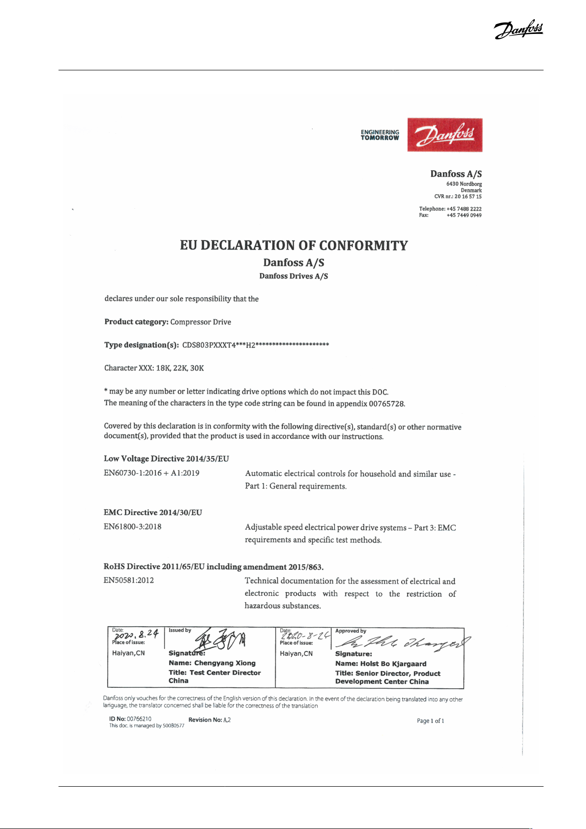
Operating Guide
1.6 CE Declaration
Introduction
AQ321748767627en-000301 / 130R05708 | Danfoss A/S © 2021.06
VLT® Compressor Drive CDS 803
Operating Guide
Introduction
AQ321748767627en-000301 / 130R0570 | 9Danfoss A/S © 2021.06

VLT® Compressor Drive CDS 803
Operating Guide
2 Safety
2.1 Safety Symbols
The following symbols are used in this manual:
D A N G E R
Indicates a hazardous situation which, if not avoided, will result in death or serious injury.
W A R N I N G
Indicates a hazardous situation which, if not avoided, could result in death or serious injury.
C A U T I O N
Indicates a hazardous situation which, if not avoided, could result in minor or moderate injury.
N O T I C E
Indicates information considered important, but not hazard-related (for example, messages relating to property damage).
Safety
2.2 Qualified Personnel
To allow trouble-free and safe operation of the unit, only qualified personnel with proven skills are allowed to transport, store, assemble, install, program, commission, maintain, and decommission this equipment.
Persons with proven skills:
•
Are qualified electrical engineers, or persons who have received training from qualified electrical engineers and are suitably
experienced to operate devices, systems, plant, and machinery in accordance with pertinent laws and regulations.
•
Are familiar with the basic regulations concerning health and safety/accident prevention.
•
Have read and understood the safety guidelines given in all manuals provided with the unit, especially the instructions given in
the Operating Guide.
•
Have good knowledge of the generic and specialist standards applicable to the specific application.
2.3 Safety Precautions
W A R N I N G
HAZARDOUS VOLTAGE
AC drives contain hazardous voltage when connected to the AC mains or connected on the DC terminals. Failure to perform
installation, start-up, and maintenance by skilled personnel can result in death or serious injury.
Only skilled personnel must perform installation, start-up, and maintenance.
-
W A R N I N G
UNINTENDED START
When the drive is connected to AC mains, DC supply, or load sharing, the motor may start at any time. Unintended start during
programming, service, or repair work can result in death, serious injury, or property damage. Start the motor with an external
switch, a fieldbus command, an input reference signal from the local control panel (LCP), via remote operation using MCT 10
software, or after a cleared fault condition.
Disconnect the drive from the mains.
-
Press [Off/Reset] on the LCP before programming parameters.
-
Ensure that the drive is fully wired and assembled when it is connected to AC mains, DC supply, or load sharing.
-
AQ321748767627en-000301 / 130R057010 | Danfoss A/S © 2021.06

Voltage [V]
Power range [kW (hp)]
Minimum waiting time (minutes)
3x200
6.0–10 (8.0–15)
15
3x400
6.0–7.5 (8.0–10)
4
3x400
10–30 (15–40)
15
VLT® Compressor Drive CDS 803
Operating Guide
Safety
W A R N I N G
DISCHARGE TIME
The drive contains DC-link capacitors, which can remain charged even when the drive is not powered. High voltage can be
present even when the warning indicator lights are off.
Failure to wait the specified time after power has been removed before performing service or repair work could result in death or
serious injury.
Stop the motor.
-
Disconnect AC mains, permanent magnet type motors, and remote DC-link supplies, including battery back-ups, UPS, and
-
DC-link connections to other drives.
Wait for the capacitors to discharge fully. The minimum waiting time is specified in the table Discharge time and is also visible
-
on the nameplate on the top of the drive.
Before performing any service or repair work, use an appropriate voltage measuring device to make sure that the capacitors
-
are fully discharged.
Table 2: Discharge Time
W A R N I N G
LEAKAGE CURRENT HAZARD
Leakage currents exceed 3.5 mA. Failure to ground the drive properly can result in death or serious injury.
Ensure that the minimum size of the ground conductor complies with the local safety regulations for high touch current
-
equipment.
W A R N I N G
EQUIPMENT HAZARD
Contact with rotating shafts and electrical equipment can result in death or serious injury.
Ensure that only trained and qualified personnel perform installation, start-up, and maintenance.
-
Ensure that electrical work conforms to national and local electrical codes.
-
Follow the procedures in this manual.
-
C A U T I O N
INTERNAL FAILURE HAZARD
An internal failure in the drive can result in serious injury when the drive is not properly closed.
Ensure that all safety covers are in place and securely fastened before applying power.
-
AQ321748767627en-000301 / 130R0570 | 11Danfoss A/S © 2021.06

Power [kW (hp)]
Clearance above/below [mm (in)]
Size
IP protection rating
3x200–240 V
3x380–480 V
H3
IP20–6.0–7.5 (8.0–10)
100 (4)
H4
IP20
6.0–7.5 (8.0–10)
10 (15)
100 (4)
H5
IP20
10 (15)
18.5–22 (25–30)
100 (4)
H6
IP20–30(40)
200 (7.9)
Power [kW (hp)]
Torque [Nm (in-lb)]
Enclosure size
IP protection rating
3x200–240 V
3x380–480 V
Mains
Motor
DC connection
Control terminals
Ground
Relay
H3
IP20–6.0–7.5 (8.0–10)
0.8 (7)
0.8 (7)
0.8 (7)
0.5 (4)
0.8 (7)
0.5 (4)
VLT® Compressor Drive CDS 803
Operating Guide
3 Installation
3.1 Mechanical Installation
3.1.1 Side-by-side Installation
The drive can be mounted side by side but requires the clearance specified in Table 3 above and below for cooling.
Table 3: Clearance Required for Cooling
N O T I C E
With IP21/NEMA Type1 option kit mounted, a distance of 50 mm (2 in) between the units is required.
Installation
3.1.2 Operating Environment
3.1.2.1 Derating for Ambient Temperature and Switching Frequency
Ensure that the ambient temperature measured over 24 hours is at least 5 °C (9 °F) lower than the maximum ambient temperature
that is specified for the drive. If the drive is operated at a high ambient temperature, decrease the constant output current. For
derating specifications, see the VLT® Compressor Drive CDS 803 Design Guide listed in
1.2 Additional Resources.
3.1.2.2 Derating for Low Air Pressure and High Altitudes
The cooling capability of air is decreased at low air pressure. For altitudes above 2000 m (6562 ft), contact Danfoss regarding PELV.
Below 1000 m (3281 ft) altitude, derating is not necessary. For altitudes above 1000 m (3281 ft), decrease the ambient temperature
or the maximum output current. Decrease the output by 1% per 100 m (328 ft) altitude above 1000 m (3281 ft) or reduce the maximum ambient cooling air temperature by 1 °C (1.8 °F) per 200 m (656 ft).
3.2 Electrical Installation
3.2.1 Electrical Installation in General
All cabling must comply with national and local regulations on cable cross-sections and ambient temperature. Copper conductors
are required. 75 °C (167 °F) is recommended.
3.2.1.1 Fastener Torque Ratings
Table 4: Tightening Torques for Enclosure Sizes H3–H6, 3x200–240 V & 3x380–480 V
AQ321748767627en-000301 / 130R057012 | Danfoss A/S © 2021.06
Power [kW (hp)]
Torque [Nm (in-lb)]
H4
IP20
6.0–7.5 (8.0–
10)
10–15 (15–20)
1.2 (11)
1.2 (11)
1.2 (11)
0.5 (4)
0.8 (7)
0.5 (4)
H5
IP20
10 (15)
18.5–22 (25–30)
1.2 (11)
1.2 (11)
1.2 (11)
0.5 (4)
0.8 (7)
0.5 (4)
H6
IP20–30 (40)
4.5 (40)
4.5 (40)
–
0.5 (4)
3 (27)
0.5 (4)
Circuit breakers
(1)
Fuse
UL
Non-ULULNon-UL
Bussmann
Bussmann
Bussmann
Bussmann
Maximum fuse
Power [kW (hp)]
Type RK5
Type RK1
Type J
Type T
Type gG
3x200–240 V
6.0 (8.0)
–
–
FRS-R-50
KTN-R50
JKS-50
JJN-50
gG-50
7.5 (10)
FRS-R-50
KTN-R50
JKS-50
JJN-50
gG-50
10 (15)
FRS-R-80
KTN-R80
JKS-80
JJN-80
gG-63
3x380–480 V
6.0 (8.0)
–
–
FRS-R-25
KTS-R25
JKS-25
JJS-25
gG-25
7.5 (10)
FRS-R-25
KTS-R25
JKS-25
JJS-25
gG-25
10 (15)
FRS-R-50
KTS-R50
JKS-50
JJS-50
gG-50
18.5 (25)
–––
JJS-80
gG-63
22 (30)
JJS-80
gG-63
30 (40)
JJS-125
gG-80
VLT® Compressor Drive CDS 803
Operating Guide
Installation
3.2.2 Fuses and Circuit Breakers
Fuses and circuit breakers ensure that possible damage to the drive is limited to damage inside the unit. Danfoss recommends fuses
on the supply side as protection. For further information, see the application note Fuses and Circuit Breakers found on www.dan-
foss.com under Service and support/Documentation/Manuals & guides.
N O T I C E
Use of fuses on the supply side is mandatory for IEC 60364 (CE) and NEC 2009 (UL) compliant installations.
3.2.2.1 Recommendation of Fuses and Circuit Breakers
Table 5: Fuses and Circuit Breakers
1
Circuit breakers have not been evaluated by Danfoss as part of the certification process.
AQ321748767627en-000301 / 130R0570 | 13Danfoss A/S © 2021.06

L1
L2
L3
3-phase
power
input
PE
PE
+10 V DC
0-10 V DC-
0-10 V DC-
50 (+10 V OUT)
54 (A IN)
53 (A IN)
55 (COM A IN/OUT)
0/4-20 mA
0/4-20 mA
42 0/4-20 mA A OUT / D OUT
45 0/4-20 mA A OUT / D OUT
18 (D IN)
19 (D IN)
27 (D IN)
29 (
D IN)
12 (+24 V OUT)
24 V (NPN)
20 (COM D IN)
O V (PNP)
24 V (NPN)
O V (PNP)
24 V (NPN)
O V (PNP)
24 V (NPN)
O V (PNP)
Bus ter.
Bus ter.
RS485
Interface
RS485
(N RS485) 69
(P RS485) 68
(Com RS485 ) 61
(PNP)-Source
(NPN)-Sink
ON=Terminated
OFF=Unterminated
ON
1 2
240 V AC 3 A
Not present on all power sizes
Do not connect shield to 61
01
02
03
relay 1
relay 2
UDC+
UDC-
Motor
U
V
W
e30bj246.10
06
05
04
240 V AC 3 A
VLT® Compressor Drive CDS 803
Operating Guide
3.2.3 Electrical Wiring
3.2.3.1 Wiring Schematic
Installation
Illustration 1: Basic Wiring Schematic Drawing
There is no access to UDC- and UDC+ on the following units:
IP20, 380–480 V, 30 kW (40 hp).
-
N O T I C E
AQ321748767627en-000301 / 130R057014 | Danfoss A/S © 2021.06
1
2
2
3
4
U
V
W
-DC
+DC
e30bb634.11
5
MAINS
MOTOR
1
Mains
2
Ground
3
Compressor
4
Relays
5
Control terminals
VLT® Compressor Drive CDS 803
Operating Guide
3.2.3.2 Terminal Overview of Enclosure Sizes H3–H5
Installation
Illustration 2: Enclosure Sizes H3–H5
AQ321748767627en-000301 / 130R0570 | 15Danfoss A/S © 2021.06

1
95
99
L1 91 / L2 92 / L3 93
U 96 /
V 97 /
W 98
03 02 01
06 05 04
2
3
4
e30bb762.12
1
Mains
2
Ground
3
Compressor
4
Relays
e30bi968.10
VLT® Compressor Drive CDS 803
Operating Guide
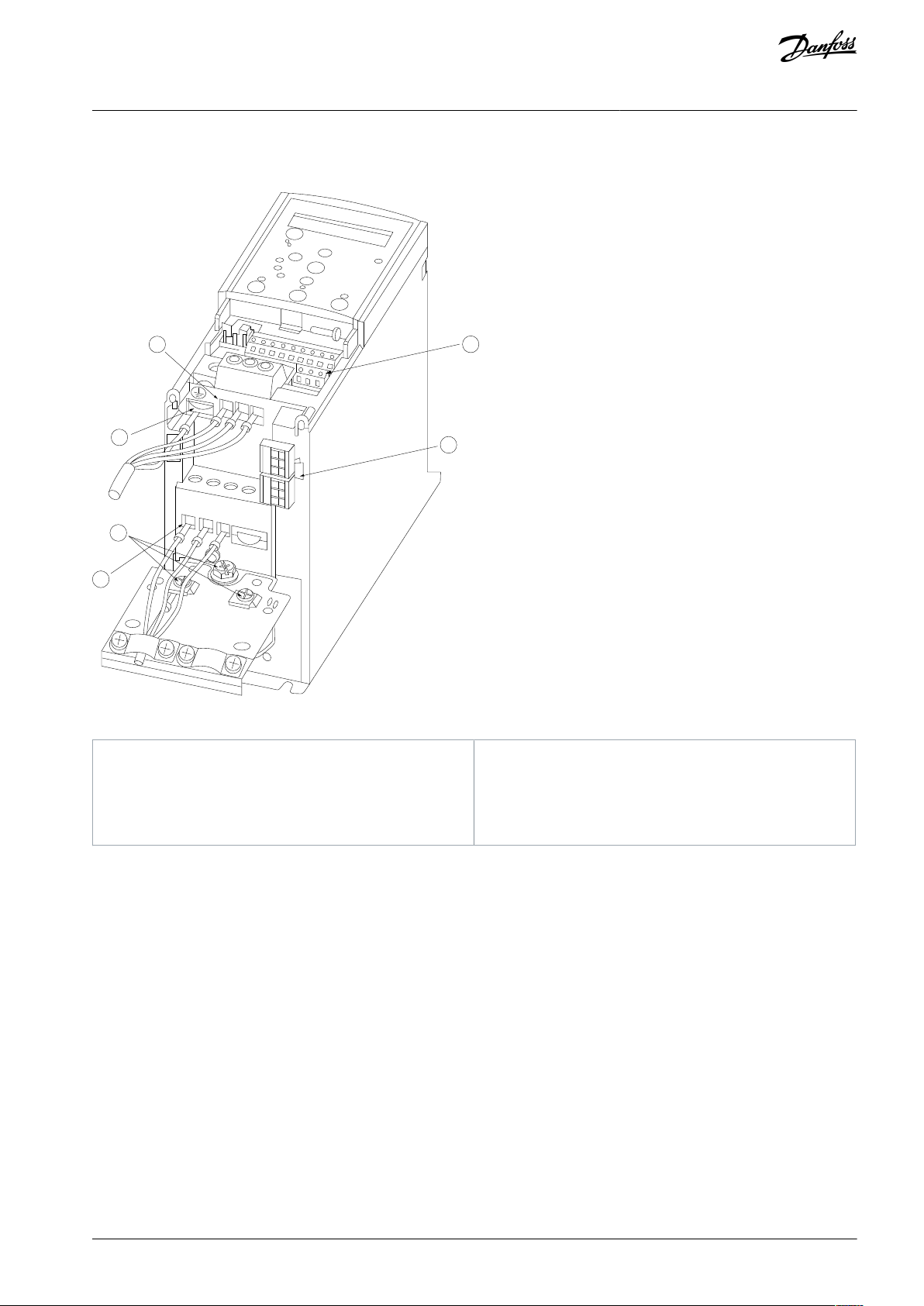
3.2.3.3 Terminal Overview of Enclosure Size H6
Installation
Illustration 3: Enclosure Size H6
3.2.3.4 Connecting to Mains and Compressor Terminals
•
Tighten all terminals in accordance with the information provided in 3.2.1.1 Fastener Torque Ratings.
•
Keep the compressor cable as short as possible to reduce the noise level and leakage currents.
•
Use a shielded/armored compressor cable to comply with the EMC emission specifications and connect this cable to both the
decoupling plate and the compressor. Also see 3.2.5 EMC-compliant Electrical Installation.
1.
Connect the ground cable to the ground terminal, then connect the mains supply to terminals L1, L2, and L3.
AQ321748767627en-000301 / 130R057016 | Danfoss A/S © 2021.06

e30bi967.10
Drive terminals
Compressor
UT1VT2W
T3
VLT® Compressor Drive CDS 803
Operating Guide
2.
Connect the ground cable to the ground terminal, then connect the compressor to terminals U, V, and W.
Table 6: Connection of Compressor to Terminals
Installation
3.2.3.5 Relay Terminals
Relay 1
•
Terminal 01: Common.
•
Terminal 02: Normally open.
•
Terminal 03: Normally closed.
Relay 2
•
Terminal 04: Common.
•
Terminal 05: Normally open.
•
Terminal 06: Normally closed.
AQ321748767627en-000301 / 130R0570 | 17Danfoss A/S © 2021.06

Relay1
Relay2
03
02
01
06
05
04
e30bi798.10
e30bd331.11
VLT® Compressor Drive CDS 803
Operating Guide
Installation
Illustration 4: Relay Outputs 1 and 2
3.2.3.6 Control Terminals
Remove the terminal cover to access the control terminals.
Use a flat-edged screwdriver to push down the lock lever of the terminal cover under the LCP, then remove the terminal cover as
shown in the following illustration.
Illustration 5: Removing the Terminal Cover
The following illustration shows all the drive control terminals. Applying start (terminal 18), connection between terminals 12-27,
and an analog reference (terminal 53 or 54, and 55) make the drive run.
The digital input mode of terminal 18, 19, 27, and 29 is set in parameter 5-00 Digital Input Mode (PNP is default value).
AQ321748767627en-000301 / 130R057018 | Danfoss A/S © 2021.06

e30bf892.10
12 20 55
181927 29 42 54
45 50 53
DIGI IN
61 68 69
N
P
COMM. GND
+24 V
GND
GND
10 V OUT
10 V/20 mA IN
0/4-20 mA A OUT/DIG OUT
BUS TER.
OFF ON
DIGI IN
DIGI IN
DIGI IN
0/4-20 mA A OUT/DIG OUT
10 V/20 mA IN
VLT® Compressor Drive CDS 803
Operating Guide
Illustration 6: Control Terminals
Installation
3.2.4 Setting Up RS485 Serial Communication
3.2.4.1 RS485 Features
RS485 is a 2-wire bus interface compatible with multi-drop network topology. This interface contains the following features:
•
Ability to select from the following communication protocols:
-
FC (default protocol)
-
Modbus RTU
•
Functions can be programmed remotely using the RS485 connection or in parameter group 8-** Communications and Options.
•
A switch (BUS TER) is provided on the control card for bus termination resistance.
N O T I C E
Altering between the supported communication protocols can be accessed and changed via the LCP as parameter 8-30 Protocol is
not available in VLT® Motion Control Tool MCT 10.
3.2.4.2 Configuring RS485 Serial Communication
Procedure
1.
Connect RS485 serial communication wiring to terminals (P RS485) 68 and (N RS485) 69.
-
Use shielded serial communication cable.
-
Properly ground the wiring. Refer to 3.2.5 EMC-compliant Electrical Installation.
AQ321748767627en-000301 / 130R0570 | 19Danfoss A/S © 2021.06

+
e30bi768.10
RS485
69
GND
68
VLT® Compressor Drive CDS 803
Operating Guide
2.
Configure all required settings such as address, baud rate, and so on in parameter group 8-** Communications and Options.
For more details on parameters, refer to VLT® Compressor Drive CDS 803 Programming Guide listed in 1.2 Additional Re-
sources.
Example
Illustration 7: RS485 Wiring Connection
Installation
3.2.5 EMC-compliant Electrical Installation
To obtain an EMC-compliant installation, be sure to follow all electrical installation instructions. Also, remember to practice the following:
•
When using relays, control cables, a signal interface, fieldbus, or brake, connect the shield to the enclosure at both ends. If the
ground path has high impedance, is noisy, or is carrying current, break the shield connection on 1 end to avoid ground current
loops.
•
Convey the currents back to the unit using a metal mounting plate. Ensure good electrical contact from the mounting plate by
securely fastening the mounting screws to the drive chassis.
•
Use shielded cables for motor output cables. An alternative is unshielded motor cables within metal conduit.
•
Ensure that motor and brake cables are as short as possible to reduce the interference level from the entire system.
•
Avoid placing cables with a sensitive signal level alongside motor and brake cables.
•
For communication and command/control lines, follow the particular communication protocol standards. For example, USB
must use shielded cables, but RS485/ethernet can use shielded UTP or unshielded UTP cables.
•
Ensure that all control terminal connections are rated protective extra low voltage (PELV).
N O T I C E
TWISTED SHIELD ENDS (PIGTAILS)
Twisted shield ends increase shield impedance at higher frequencies, which increases the leakage current.
Use integrated shield clamps instead of twisted shield ends.
-
N O T I C E
SHIELDED CABLES
If shielded cables or metal conduits are not used, the unit and the installation do not meet regulatory limits on radio frequency
(RF) emission levels.
N O T I C E
EMC INTERFERENCE
Failure to isolate power, motor, and control cables can result in unintended behavior or reduced performance.
Use shielded cables for motor and control wiring.
-
Provide a minimum 200 mm (7.9 in) separation between mains input, motor cables, and control cables.
-
AQ321748767627en-000301 / 130R057020 | Danfoss A/S © 2021.06

VLT® Compressor Drive CDS 803
Operating Guide
Installation
N O T I C E
EMI/EMC NON-COMPLIANCE
Panel components not installed by Danfoss will invalidate the EMI/EMC compliance and other certifications.
N O T I C E
INSTALLATION AT HIGH ALTITUDE
There is a risk for overvoltage. Isolation between components and critical parts could be insufficient and may not comply with
PELV requirements.
Use external protective devices or galvanic isolation. For installations above 2000 m (6500 ft) altitude, contact Danfoss re-
-
garding protective extra low voltage (PELV) compliance.
N O T I C E
PROTECTIVE EXTRA LOW VOLTAGE (PELV) COMPLIANCE
Prevent electric shock by using PELV electrical supply and complying with local and national PELV regulations.
AQ321748767627en-000301 / 130R0570 | 21Danfoss A/S © 2021.06

L1
L2L3PEL1L2L3PEPEu
v
w
2
1
3
5
IEC 60309
16
17
18
14
12
8
7
10
9
4
11
13
446
15
90
+DC
BR-
B
M
AINS
L1 L2 L3
91 92 93
RELA
Y 1 RELA
Y 2
99
- L
C -
UV
W
MO
T
OR
VLT® Compressor Drive CDS 803
Operating Guide
Installation
Illustration 8: Example of Proper EMC Installation
AQ321748767627en-000301 / 130R057022 | Danfoss A/S © 2021.06

1
Programmable logic controller (PLC)
2
Minimum 16 mm2 (6 AWG) equalizing cable
3
Control cables
4
Minimum 200 mm (7.9 in) between control cables,
motor cables, and mains cables
5
Mains supply
6
Bare (unpainted) surface
7
Star washers
8
Brake cable (shielded)
9
Motor cable (shielded)
10
Mains cable (unshielded)
11
Output contactor
12
Cable insulation stripped
13
Common ground busbar. Follow local and national
requirements for cabinet grounding.
14
Brake resistor
15
Metal box
16
Connection to motor
17
Motor
18
EMC cable gland
VLT® Compressor Drive CDS 803
Operating Guide
Installation
AQ321748767627en-000301 / 130R0570 | 23Danfoss A/S © 2021.06

e30bb765.11
B
a
c
k
Com.
1-20 Motor Power
[5] 0.37kW - 0.5HP
Setup 1
A
B
1
12
13
14
15
11
11
10
9
8
7
6
5
4
3
2
C
D
Status
Main
Menu
Quick
Menu
Hand
On
OK
M
enu
Off
Reset
Auto
On
Alarm
Warn.
On
11
1
Parameter number and name.
2
Parameter value.
VLT® Compressor Drive CDS 803
Operating Guide
Commissioning
4 Commissioning
4.1 Programming Interfaces
The drive can be programmed in 3 different ways:
•
Locally via the LCP.
•
Externally via the RS485 interface by either
-
using Modbus RTU
-
or by installing VLT® Motion Control Tool MCT 10.
For the full menu and parameter specifications, refer to the VLT® Compressor Drive CDS 803 Programming Guide listed in 1.2 Addi-
tional Resources.
4.2 Local Control Panel (LCP)
The LCP is divided into 4 functional sections.
•
A. Display
•
B. Menu key
•
C. Navigation keys and indicator lights
•
D. Operation keys and indicator lights
Illustration 9: Local Control Panel (LCP)
A. Display
The LCD display is illuminated with 2 alphanumeric lines. Table 7 describes the information that can be read from the display.
Table 7: Legend to Section A
AQ321748767627en-000301 / 130R057024 | Danfoss A/S © 2021.06

3
Setup number shows the active setup and the edit setup. If the same setup acts as both active and edit setup, only that setup
number is shown (factory setting). When active and edit setup differ, both numbers are shown in the display (setup 12). The
number flashing indicates the edit setup.
4
Motor direction is shown to the bottom left of the display – indicated by a small arrow pointing either clockwise or counterclockwise.
5
The triangle indicates if the LCP is in Status, Quick Menu, or Main Menu.
6
Com. (yellow indicator): Flashes during bus communication.
7
On (green indicator): Control section is working correctly.
8
Warn. (yellow indicator): Indicates a warning.
9
Alarm (red indicator): Indicates an alarm.
10
[Back]: For moving to the previous step or layer in the navigation structure.
11
[▵] [▿] [▹]: For navigating among parameter groups and parameters, and within parameters. They can also be used for setting local reference.
12
[OK]: For selecting a parameter and for accepting changes to parameter settings.
13
[Hand On]: Starts the motor and enables control of the drive via the LCP.
N O T I C E
[2] Coast inverse is the default option for parameter 5-12 Terminal 27 Digital Input. If there is no 24 V supply to terminal 27,
[Hand On] does not start the compressor. Connect terminal 12 to terminal 27.
14
[Off/Reset]: Stops the compressor (Off). If in alarm mode, the alarm is reset.
15
[Auto On]: The drive is controlled either via control terminals or serial communication.
VLT® Compressor Drive CDS 803
Operating Guide
B. Menu key
Press [Menu] to select among Status, Quick Menu, or Main Menu.
C. Navigation keys and indicator lights
Table 8: Legend to Section C
Commissioning
D. Operation keys and indicator lights
Table 9: Legend to Section D
4.2.1 Programming via the Quick Menu
Procedure
1.
To enter the Quick Menu, press [Menu] until indicator in display is placed above Quick Menu.
2.
Press [▵] [▿] to select quick guide, closed-loop setup, compressor setup, or changes made, then press [OK].
3.
Press [▵] [▿] to browse through the parameters in the Quick Menu.
Press [OK] to select a parameter.
4.
Press [▵] [▿] to change the value of a parameter setting.
5.
Press [OK] to accept the change.
6.
7.
Press either [Back] twice to enter Status, or press [Menu] once to enter Main Menu.
4.2.2 Programming via the Main Menu
Procedure
1.
Press [Menu] until indicator in display is placed above Main Menu.
Press [▵] [▿] to browse through the parameter groups.
2.
AQ321748767627en-000301 / 130R0570 | 25Danfoss A/S © 2021.06
VLT® Compressor Drive CDS 803
Operating Guide
3.
Press [OK] to select a parameter group.
4.
Press [▵] [▿] to browse through the parameters in the specific group.
5.
Press [OK] to select the parameter.
6.
Press [▵] [▿] to set/change the parameter value.
7.
Press [OK] to accept the change or press [Back] to go back to the previous level.
Commissioning
4.2.3 Data Transfer from Drive to LCP
Once the setup of a drive is complete, Danfoss recommends storing the data in the LCP or on a PC via VLT® Motion Control Tool
MCT 10.
W A R N I N G
Stop the compressor before performing this operation.
Procedure
1.
Go to parameter 0-50 LCP Copy.
2.
Press [OK].
3.
Select [1] All to LCP.
Press [OK].
4.
4.2.4 Data Transfer from LCP to Drive
Connect the LCP to another drive to copy the parameter settings to this drive as well.
W A R N I N G
Stop the compressor before performing this operation.
Procedure
1.
Go to parameter 0-50 LCP Copy.
2.
Press [OK].
3.
Select [2] All from LCP.
4.
Press [OK].
4.2.5 Restoring Factory Default Settings
There are 2 different ways of initializing the drive to factory default settings:
•
Via parameter 14-22 Operation Mode (this is the recommended way).
Two-finger initialization
•
Some parameters will not be reset, see more details in
and 4.2.5.2 Two-finger Initialization.
4.2.5.1 Recommended Initialization (via Parameter 14-22 Operation Mode)
Initialization of the drive to default settings (via parameter 14-22 Operation Mode).
Procedure
1.
Select parameter 14-22 Operation Mode.
2.
Press [OK].
3.
Select [2] Initialisation and press [OK].
Cut off the mains supply and wait until the display turns off.
4.
Reconnect the mains supply.
5.
4.2.5.1 Recommended Initialization (via Parameter 14-22 Operation Mode)
The drive is now reset, except the following parameters:
Parameter 1-06 Clockwise Direction
Parameter 1-13 Compressor Selection
Parameter 4-18 Current Limit
Parameter 8-30 Protocol
AQ321748767627en-000301 / 130R057026 | Danfoss A/S © 2021.06

VLT® Compressor Drive CDS 803
Operating Guide
Parameter 8-31 Address
Parameter 8-32 Baud Rate
Parameter 8-33 Parity / Stop Bits
Parameter 8-35 Minimum Response Delay
Parameter 8-36 Maximum Response Delay
Parameter 8-37 Maximum Inter-char delay
Parameter 15-00 Operating hours to parameter 15-05 Over Volt's
Parameter 15-03 Power Up's
Parameter 15-04 Over Temp's
Parameter 15-05 Over Volt's
Parameter 15-30 Alarm Log: Error Code
Parameter group 15-4* Drive identification parameters
4.2.5.2 Two-finger Initialization
Procedure
1.
Power off the drive.
2.
Press [OK] and [Menu].
3.
Power up the drive while still pressing the keys above for 10 s.
Commissioning
The drive is now reset, except the following parameters:
Parameter 1-06 Clockwise Direction
Parameter 15-00 Operating hours
Parameter 15-03 Power Up's
Parameter 15-04 Over Temp's
Parameter 15-05 Over Volt's
Parameter 15-30 Alarm Log: Error Code
Parameter group 15-4* Drive identification parameters
Initialization of parameters is confirmed by AL80 in the display after the power cycle.
4.3 Starting Up the Drive for the First Time
The procedure in this section requires user-wiring and application programming to be completed. The following procedure is recommended after application setup is completed.
1.
Press [Auto On].
If warnings or alarms occur, see the Warnings and Alarms section.
Apply an external run command. Examples of external run commands are a switch, button, or programmable logic control-
2.
ler (PLC).
Adjust the speed reference throughout the speed range.
3.
Ensure that the system is working as intended by checking the sound and vibration levels of the compressor.
4.
Remove the external run command.
5.
AQ321748767627en-000301 / 130R0570 | 27Danfoss A/S © 2021.06
Status
Color
Warning
Constant yellow light
Alarm
Flashing red light
VLT® Compressor Drive CDS 803
Operating Guide
Troubleshooting
5 Troubleshooting
5.1 Acoustic Noise or Vibration
If the compressor application makes noise or vibrations at certain frequencies, adjust the following parameters to avoid resonance
problems within the system.
•
Upper and lower frequency limits, Parameter group 4-6* Speed Bypass.
•
Switching pattern and switching frequency, parameter group 14-0* Inverter Switching.
5.2 Warnings and Alarms
A warning or an alarm is signaled by the relevant indicator on the front of the drive and indicated by a code on the display.
A warning remains active until its cause is no longer present. Under certain circumstances, operation of the compressor may still be
continued. Warning messages may be critical.
In the event of an alarm, the drive has tripped. To restart operation, reset alarms once their cause has been rectified.
This may be done in 4 ways:
By pressing [Reset].
•
Via a digital input with the Reset function.
•
Via serial communication.
•
•
By resetting automatically using the [Auto Reset] function, see parameter 14-20 Reset Mode.
A trip is the action following an alarm. The trip coasts the compressor and is reset by pressing [Reset] or by a digital input (parameter
group 5-1* Digital Inputs). The original event that caused an alarm cannot damage the drive or cause dangerous conditions. A trip
lock is an action when an alarm occurs, which could damage the drive or connected parts. A trip lock situation can only be reset by
cycling power.
Refer to the VLT® Compressor Drive CDS 803 Programming Guide listed in
gramming.
1.2 Additional Resources for parameter details and pro-
Table 10: Indicator Lights
The alarm words, warning words and extended status words can be read out via serial bus or optional fieldbus for diagnosis. See
also parameter 16-90 Alarm Word, parameter 16-92 Warning Word, and parameter 16-94 Ext. Status Word.
N O T I C E
MOTOR RESTART
After a manual reset pressing [Reset], press [Auto On] or [Hand On] to restart the motor.
If an alarm cannot be reset, the reason may be that its cause has not been rectified, or the alarm is trip-locked, see Table 11.
C A U T I O N
ALARM RESET
Alarms that are trip-locked offer extra protection, meaning that the mains supply must be switched off before the alarm can be
reset. After being switched back on, the drive is no longer blocked and may be reset as described above once the cause has been
rectified.
Alarms that are not trip-locked can also be reset using the automatic reset function in parameter 14-20 Reset Mode (Warning: auto-
matic wake-up is possible!)
alarm for a given fault.
Table 11 specifies whether a warning occurs before an alarm, or whether to show a warning or an
AQ321748767627en-000301 / 130R057028 | Danfoss A/S © 2021.06
Fault
number
Fault text
Warning
Alarm
Trip
locked
Cause of problem
2
Live zero error
X
X
Signal on terminal 53 or 54 is less than 50% of the value set in
parameter 6-10 Terminal 53 Low Voltage, parameter 6-12 Terminal 53 Low Current, parameter 6-20 Terminal 54 Low Voltage, or
parameter 6-22 Terminal 54 Low Current. See also parameter
group 6-0* Analog I/O Mode.
3
No motor
X
(1)
No motor is connected.
4
Mains ph. loss
XXX
Missing phase on the supply side or too high voltage imbalance. Check the supply voltage. See parameter 14-12 Response
to Mains Imbalance.
7
DC over volt
XXDC-link voltage exceeds limit.
8
DC under volt
X
X
DC-link voltage drops below voltage warning low limit.
9
Inverter overld.
XXMore than 100% load for too long.
10
Motor ETR over
X
(2)
X
The compressor is too hot due to more than 100% load for too
long.11Motor th over
XXThe thermistor or the thermistor connection is disconnected.
13
Overcurrent
XXX
Inverter peak current limit is exceeded.
14
Earth Fault
XXX
Discharge from output phases to ground.
16
Short Circuit
XXShort circuit in the motor or on the motor terminals.
17
Ctrl. word TO
X
X
No communication to the drive. See parameter group 8-0*
General Settings.
18
Start failed
X
The speed has not been able to exceed parameter 1-78 Motor
Start Min Speed [Hz] during start within the allowed time.
30
U phase loss
X
X
(2)
Motor phase U is missing. Check the phase.
For 6–10 kW drives: See parameter 4-58 Missing Motor Phase
Function.
31
V phase loss
X
X
(2)
Motor phase V is missing. Check the phase.
For 6–10 kW drives: See parameter 4-58 Missing Motor Phase
Function.
32
W phase loss
X
X
(2)
Motor phase W is missing. Check the phase.
For 6–10 kW drives: See parameter 4-58 Missing Motor Phase
Function.
36
Mains failure
XXSupply voltage to the drive is lost.
38
Internal fault
XXContact the local Danfoss supplier.
VLT® Compressor Drive CDS 803
Operating Guide
Table 11: Warnings and Alarms
Troubleshooting
AQ321748767627en-000301 / 130R0570 | 29Danfoss A/S © 2021.06

Fault
number
Fault text
Warning
Alarm
Trip
locked
Cause of problem
46
Gate drive voltage
fault
XXThe supply on the power card is out of range.
47
24V supply low
XXX
24 V DC may be overloaded.
49
Speed limit
X
The compressor runs at a speed lower than specified in pa-
rameter 1-87 Compressor Min Speed for Trip [Hz].
50
AMA calibration
X
AMA calibration failed
51
AMA check
U
nom,Inom
X
Motor voltage, current and power configured wrong in parameters.
52
AMA low,I
nom
X
Motor current too low.
53
AMA big motor
X
Motor is too large for the AMA to be performed.
54
AMA small mot
X
Motor is too small for the AMA to be performed.
55
AMA par. range
X
Parameter values found is outside of the acceptable range.
56
AMA interrupt
X
The AMA is interrupted by user.
57
AMA timeout
X
The AMA takes too long time to complete.
58
AMA internal
X
Contact the local Danfoss supplier.
59
Current limit
X
X
The current is higher than the value in parameter 4-18 Current
Limit.
60
External interlock
X
External interlock has been activated. To resume normal operation, apply 24 V DC to the terminal programmed for external
interlock and reset the drive (via serial communication, digital
I/O, or by pressing [Off/Reset]).
66
Heat Sink Temperature Low
X
(3)
This warning is based on the temperature sensor in the IGBT
module.
69
Pwr. Card Temp
XXX
The internal temperature has exceeded the allowed operating
boundary. Check that the ambient operating temperature is
within the limits. Check the fan operation.
80
Drive initialised
X
All parameter settings are initialized to default settings.
87
Auto DC Braking
X
The drive is auto DC braking.
95
Broken belt
X
(2)X(2)
The torque is below the torque level set for no load indicating
a broken belt.
96
Start delayed
X
Power to the drive has been on for a shorter time than specified in parameter 28-01 Interval Between Starts twice.
97
Stop delayed
X
Stopping the motor has been delayed due to short cycle protection being active.
VLT® Compressor Drive CDS 803
Operating Guide
Troubleshooting
AQ321748767627en-000301 / 130R057030 | Danfoss A/S © 2021.06

Fault
number
Fault text
Warning
Alarm
Trip
locked
Cause of problem
99
Locked rotor
X
The rotor is blocked or cannot run due to heavy load.
126
Motor Rotating
X
High back EMF voltage. Stop the rotor of the PM motor.
127
Back EMF too high
X
The drive cannot start the motor due to the rotor running at a
higher speed than normal condition.
208
ORM Fault
XXRunning in hand mode with low speed for too long time.
VLT® Compressor Drive CDS 803
Operating Guide
1
Only applicable for 18–30 kW.
2
Only applicable for 6–10 kW.
3
Only applicable for 30 kW.
Troubleshooting
For full specifications of warnings and alarms, refer to the VLT® Compressor Drives CDS 803 Programming Guide listed in
tional Resources.
1.2 Addi-
AQ321748767627en-000301 / 130R0570 | 31Danfoss A/S © 2021.06

P6K0
P7K5
P10K
Typical shaft output [kW]
6.0
7.510Typical shaft output [hp]
8.01015
Enclosure size
H4H4H5
Maximum cable size in terminals (mains, compressor) [mm2 (AWG)]
16 (6)
16 (6)
16 (6)
Output current @ 40 °C (104 °F) ambient temperature
Continuous (3x200–240 V) [A]
222842
Intermittent (3x200–240 V) [A]
24.2
30.8
46.2
Output current @ 50 °C (122 °F) ambient temperature
Continous (3x200–240 V) [A]
19.82333
Intermittent (3x200–240 V) [A]
21.8
25.3
36.3
Maximum input current
Continuous (3x200–240 V) [A]
21
28.341Intermittent (3x200–240 V) [A]
23.1
31.1
45.1
Maximum mains fuses, see 3.2.2.1 Recommendation of Fuses and Circuit Breakers
Estimated power loss [W], best case/typical
(1)
182/204
229/268
369/386
Weight enclosure protection IP20 [kg (lb)]
7.9 (17.4)
7.9 (17.4)
9.5 (22.9)
Efficiency [%], best case/typical
(2)
97.3/97.1
98.5/97.1
97.2/97.1
P6K0
P7K5
P10K
P18K
P22K
P30K
Typical shaft output [kW]
6.0
7.51018.52230
Typical shaft output [hp]
8.01015253040Enclosure size
H3H3H4H5H5
H6
Maximum cable size in terminals (mains, motor) [mm
2
(AWG)]
4 (10)
4 (10)
16 (6)
16 (6)
16 (6)
35 (2)
VLT® Compressor Drive CDS 803
Operating Guide
6 Specifications
6.1 Electrical Data
6.1.1 Electrical Data 3x200–240 V AC
Table 12: 3x200–240 V AC
Specifications
1
Applies to dimensioning of drive cooling. If the switching frequency is higher than the default setting, the power losses may increase. LCP and
typical control card power consumptions are included. For power loss data according to EN 50598-2, refer to Danfoss
2
Efficiency measured at nominal current. For energy efficiency class, see
mart website.
6.6 Conforming Standards. For part load losses, see Danfoss MyDrive® ecoS-
6.1.2 Electrical Data 3x380–480 V AC
Table 13: 3x380–480 V AC
MyDrive® ecoSmart website.
AQ321748767627en-000301 / 130R057032 | Danfoss A/S © 2021.06

P6K0
P7K5
P10K
P18K
P22K
P30K
Output current @ 40 °C (104 °F) ambient temperature (45 °C (113 °F) for 30 kW)
Continuous (3x380–440 V) [A]
12
15.523374461
Intermittent (3x380–440 V)[A]
13.2
17.1
25.3
40.7
46.8
67.1
Continuous (3x441–480 V) [A]
111421374461Intermittent (3x441–480 V) [A]
12.1
15.4
23.1
40.7
46.8
67.1
Output current @ 50 °C (122 °F) ambient temperature (52 °C (125 °F) for 18.5–22 kW)
Continuous (3x380–440 V) [A]
10.91420.93744
48.8
Intermittent (3x380–440 V) [A]
12
15.42340.7
46.8
53.7
Continuous (3x441–480 V) [A]
10
12.6
19.13744
41.6
Intermittent (3x441–480 V) [A]
11
13.92140.7
46.8
45.8
Maximum input current
Continuous (3x380–440 V) [A]
11.2
15.1
22.1
35.2
42.657Intermittent (3x380–440 V) [A]
12.3
16.6
24.3
38.7
45.7
62.7
Continuous (3x441–480 V) [A]
9.4
12.6
18.4
34.8
41.5
55.8
Intermittent (3x441–480 V) [A]
10.3
13.9
20.2
38.2
44.2
60.5
Maximum mains fuses, see 3.2.2.1 Recommendation of Fuses and Circuit Breakers.
Estimated power loss [W], best case/typical
(1)
104/131
159/198
248/274
412/456
475/523
733
Weight enclosure protection rating IP20 [kg (lb)]
4.3 (9.5)
4.5 (9.9)
7.9 (17.4)
9.5 (20.9)
9.5 (20.9)
24.5 (54)
Efficiency [%], best case/typical
(2)
98.4/98
98.2/97.8
98.1/97.9
98.1/97.9
98.1/97.9
97.8
Supply voltage
200–240 V ±10%
Supply voltage
380–480 V ±10%
Supply frequency
50/60 Hz
Maximum imbalance temporary between mains phases
3.0% of rated supply voltage
True power factor (λ)
≥0.9 nominal at rated load
Displacement power factor (cosφ) near unity
(>0.98)
Switching on the input supply L1, L2, L3 (power-ups)
Maximum 2 times/minute
Environment according to EN 60664-1
Overvoltage category III/pollution degree 2
The unit is suitable for use on a circuit capable of delivering not
more than 100000 A
rms
symmetrical Amperes, 240/480 V maxi-
mum.
Output voltage
0–100% of supply voltage
VLT® Compressor Drive CDS 803
Operating Guide
Specifications
1
Applies to dimensioning of drive cooling. If the switching frequency is higher than the default setting, the power losses may increase. LCP and
typical control card power consumptions are included. For power loss data according to EN 50598-2, refer to Danfoss
2
Efficiency measured at nominal current. For energy efficiency class, see
mart website.
6.6 Conforming Standards. For part load losses, see Danfoss MyDrive® ecoS-
6.2 Mains Supply (L1, L2, L3)
6.3 Compressor Output (U, V, W)
MyDrive® ecoSmart website.
AQ321748767627en-000301 / 130R0570 | 33Danfoss A/S © 2021.06

Output frequency
0–200 Hz (VVC+), 0–400 Hz (u/f)
Switching on output
Unlimited
Ramp times
0.05–3600 s
Terminal number
50
Output voltage
10.5 V ±0.5 V
Maximum load
25 mA
Terminal number
12
Maximum load
80 mA
Number of analog inputs
2
Terminal number
53, 54
Terminal 53 mode
Parameter 6-61 Terminal 53 Setting: 1=voltage, 0=current
Terminal 54 mode
Parameter 6-63 Terminal 54 Setting: 1=voltage, 0=current
Voltage level
0–10 V
Input resistance, R
i
Approximately 10 kΩ
Maximum voltage
20 V
Current level
0/4–20 mA (scalable)
Input resistance, R
i
<500 Ω
Maximum current
29 mA
Resolution on analog input
10 bit
Number of programmable analog outputs
2
Terminal number
42, 45
(1)
Current range at analog output
0/4–20 mA
The load resistor to common at analog out
500 Ω
Maximum voltage at analog output
17 V
Accuracy on analog output
Maximum error: 0.4% of full scale
Resolution on analog output
10 bit
Programmable digital inputs
4
Terminal number
18, 19, 27, 29
VLT® Compressor Drive CDS 803
Operating Guide
6.4 Control Input/Output
6.4.1 10 V DC Output
The 10 V DC output is galvanically isolated from the supply voltage (PELV) and other high-voltage terminals.
6.4.2 24 V DC Output
The 24 V DC output is galvanically isolated from the supply voltage (PELV) and other high-voltage terminals.
Specifications
6.4.3 Analog Inputs
The analog inputs are galvanically isolated from the supply voltage (PELV) and other high-voltage terminals.
6.4.4 Analog Outputs
1
Terminals 42 and 45 can also be programmed as digital outputs.
The analog outputs are galvanically isolated from the supply voltage (PELV) and other high-voltage terminals.
6.4.5 Digital Inputs
AQ321748767627en-000301 / 130R057034 | Danfoss A/S © 2021.06

Logic
PNP or NPN
Voltage level
0–24 V DC
Voltage level, logic 0 PNP
<5 V DC
Voltage level, logic 1 PNP
>10 V DC
Voltage level, logic 0 NPN
>19 V DC
Voltage level, logic 1 NPN
<14 V DC
Maximum voltage on input
28 V DC
Input resistance, R
i
Approximately 4 kΩ
Digital input 29 as thermistor input
Fault: >2.9 kΩ and no fault: <800 Ω
Digital input 29 as pulse input
Maximum frequency 32 kHz push-pull-driven & 5 kHz (O.C.)
Number of digital outputs
2
Terminals 42 and 45
Terminal number
42, 45
(1)
Voltage level at digital output
17 V
Maximum output current at digital output
20 mA
The load resistor at digital output
1 kΩ
Programmable relay output
2
Relay 01 and 02
01–03 (NC), 01–02 (NO), 04–06 (NC), 04–05 (NO)
Maximum terminal load (AC-1)
(1)
on 01–02/04–05 (NO) (Resistive
load)
250 V AC, 3 A
Maximum terminal load (AC-15)
(1)
on 01–02/04–05 (NO) (Induc-
tive load @ cosφ 0.4)
250 V AC, 0.2 A
Maximum terminal load (DC-1)
(1)
on 01–02/04–05 (NO) (Resistive
load)
30 V DC, 2 A
Maximum terminal load (DC-13)
(1)
on 01–02/04–05 (NO) (Induc-
tive load)
24 V DC, 0.1 A
Maximum terminal load (AC-1)
(1)
on 01–03/04–06 (NC) (Resistive
load)
250 V AC, 3 A
Maximum terminal load (AC-15)
(1)
on 01–03/04–06 (NC) (Inductive
load @ cosφ 0.4)
250 V AC, 0.2 A
Maximum terminal load (DC-1)
(1)
on 01–03/04–06 (NC) (Resistive
load)
30 V DC, 2 A
Minimum terminal load on 01–03 (NC), 01–02 (NO)
24 V DC 10 mA, 24 V AC 20 mA
Environment according to EN 60664-1
Overvoltage category III/pollution degree 2
Programmable relay output
2
VLT® Compressor Drive CDS 803
Operating Guide
The digital inputs are galvanically isolated from the supply voltage (PELV) and other high-voltage terminals.
6.4.6 Digital Outputs
Specifications
1
Terminals 42 and 45 can also be programmed as analog output.
The digital outputs are galvanically isolated from the supply voltage (PELV) and other high-voltage terminals.
6.4.7 Relay Outputs, Enclosure Sizes H3–H5
1
IEC 60947 parts 4 and 5. Endurance of the relay varies with different load type, switching current, ambient temperature, drive configuration, work-
ing profile, and so forth. Mount a snubber circuit when connecting inductive loads to the relays.
The relay outputs are galvanically isolated from the supply voltage (PELV) and other high-voltage terminals.
6.4.8 Relay Outputs, Enclosure Size H6
AQ321748767627en-000301 / 130R0570 | 35Danfoss A/S © 2021.06

Relay 01 and 02
01–03 (NC), 01–02 (NO), 04–06 (NC), 04–05 (NO)
Maximum terminal load (AC-1)
(1)
on 04–05 (NO) (Resistive load)
(2)
(3)
400 V AC, 2 A
Maximum terminal load (AC-15)
(1)
on 04–05 (NO) (Inductive load
@ cosφ 0.4)
240 V AC, 0.2 A
Maximum terminal load (DC-1)
(1)
on 04–05 (NO) (Resistive load)
80 V DC, 2 A
Maximum terminal load (DC-13)
(1)
on 04–05 (NO) (Inductive load)
24 V DC, 0.1 A
Maximum terminal load (AC-1)
(1)
on 04–06 (NC) (Resistive load)
240 V AC, 4 A
Maximum terminal load (AC-15)
(1)
on 04–06 (NC) (Inductive load
@ cosφ 0.4)
240 V AC, 0.2 A
Maximum terminal load (DC-1)
(1)
on 04–06 (NC) (Resistive load)
50 V DC, 2 A
Maximum terminal load (DC-13)
(1)
on 04–06 (NC) (Inductive load)
24 V DC, 0.1 A
Minimum terminal load on 01–03 (NC), 01–02 (NO), 04–06 (NC),
04–05 (NO)
24 V DC 10 mA, 24 V AC 20 mA
Environment according to EN 60664-1
Overvoltage category III/pollution degree 2
Terminal number
68 (P, TX+, RX+), 69 (N, TX-, RX-)
Terminal number
61 common for terminals 68 and 69
Enclosure protection rating
IP20
Enclosure kit available
IP21, TYPE 1
Maximum vibration exposure
1.0 g
Maximum relative humidity
5–95% (IEC 60721-3-3; Class 3K3 (non-condensing) during opera-
tion)
Aggressive environment (IEC 60721-3-3), coated (standard), enclosure sizes H3–H5
Class 3C3
Aggressive environment (IEC 60721-3-3), non-coated enclosure
size H6
Class 3C2
Environmental testing (IEC 60068-2-43 H2S)
10 days
Ambient temperature, enclosure sizes H3–H5, 6–10 kW/8–15 hp
(1)
50 °C (122 °F)
Ambient temperature, enclosure size H5, 18–22 kW/25–30 hp
(1)
52 °C (125.6 °F)
Ambient temperature, enclosure size H6, 30 kW/40 hp
(1)
45 °C (113 °F)
Minimum ambient temperature during full-scale operation
0 °C (32 °F)
Minimum ambient temperature at reduced performance, enclosure sizes H3–H5
-20 °C (-4 °F)
Minimum ambient temperature at reduced performance, enclosure size H6
-10 °C (14 °F)
Temperature during storage/transport
-30 to +65/70 °C (-22 to +149/158°F)
Maximum altitude above sea level without derating
1000 m (3281 ft)
Maximum altitude above sea level with derating
3000 m (9843 ft)
VLT® Compressor Drive CDS 803
Operating Guide
1
IEC 60947 parts 4 and 5. Endurance of the relay varies with different load type, switching current, ambient temperature, drive configuration, work-
ing profile, and so forth. Mount a snubber circuit when connecting inductive loads to the relays.
2
Overvoltage Category II.
3
UL applications 250 V AC, 3 A.
Specifications
The relay outputs are galvanically isolated from the supply voltage (PELV) and other high-voltage terminals.
6.4.9 RS485 Serial Communication
The RS485 serial communication outputs are galvanically isolated from the supply voltage (PELV) and other high-voltage terminals.
6.5 Ambient Conditions
AQ321748767627en-000301 / 130R057036 | Danfoss A/S © 2021.06

Derating for high altitude, see 3.1.2.2 Derating for Low Air Pres-
sure and High Altitudes.
Safety standards
EN/IEC 61800-5-1, UL 508C, EN/IEC/UL 60730-1
EMC standards, Emission
EN 61800-3, EN 61000-6-3/4, EN 55011, IEC 61800-3
EMC standards, Immunity
EN 61800-3, EN 61000-3-12, EN 61000-6-1/2, EN 61000-4-2, EN
61000-4-3, EN 61000-4-4, EN 61000-4-5, EN 61000-4-6
Energy efficiency class
(1)
IE2
Maximum compressor cable length, shielded/armored (EMC-correct installation)
See EMC Emission Test Results in the VLT® Compressor Drive De-
sign Guide listed in 1.2 Additional Resources.
Maximum compressor cable length, unshielded/unarmoured
50 m (164 ft)
Maximum cross-section to compressor, mains
See 6.1 Electrical Data for more information
Cross-section DC terminals for filter feedback on enclosure size
H3
4 mm2/11 AWG
Cross-section DC terminals for filter feedback on enclosure sizes
H4–H6
16 mm2/6 AWG
Maximum cross-section to control terminals, rigid wire
2.5 mm2/14 AWG
Maximum cross-section to control terminals, flexible wire
2.5 mm2/14 AWG
Minimum cross-section to control terminals
0.05 mm2/30 AWG
VLT® Compressor Drive CDS 803
Operating Guide
1
Refer to 3.1 Mechanical Installation.
6.6 Conforming Standards
1
Determined according to EN 50598-2 at:
Rated load.
•
•
90% rated frequency.
•
Switching frequency factory setting.
•
Switching pattern factory setting.
•
For power loss data according to EN 50598-2, refer to Danfoss MyDrive® ecoSmart website.
Specifications
N O T I C E
The VLT® Compressor Drive CDS 803 with SXXX in the type code is certified against UL 508C. Example:
CDS803P7K5T4E20H4XXCXXXSXXXXAXBXCXXXXDX
The VLT® Compressor Drive CDS 803 with S096 in the type code is certified against UL/EN/IEC 60730-1. Example:
CDS803P30KT4E20H2XXXXXXS096XAXBXCXXXXDX
6.7 Cable Lengths and Cross-sections
6.8 Acoustic Noise
Acoustic noise from the drives comes from 3 sources:
•
DC-link coils
•
Integral fan
•
RFI filter inductor
AQ321748767627en-000301 / 130R0570 | 37Danfoss A/S © 2021.06

Enclosure
Level [dBA]
(1)
H3
53.8H464H563.7H671.5
Enclosure size
200–240 V AC
[kW (hp)]
380–480 V AC [kW
(hp)]
IP rating
Maximum
weight [kg (lb)]
Height [mm
(in)]
Width [mm
(in)]
Depth [mm
(in)]H3–
6.0–7.5 (8.0–10)
IP20
4.5 (9.9)
280 (11)
155 (6.1)
320 (12.6)
H4
6.0–7.5 (8.0–10)
10 (15)
IP20
7.9 (17.4)
380 (15)
200 (7.9)
315 (12.4)
H5
10 (15)
18.5–22 (25–30)
IP20
9.5 (20.9)
395 (15.6)
233 (9.2)
380 (15)
H6
–
30 (40)
IP20
24.5 (54.0)
850 (33.5)
370 (15.6)
460 (18.1)
VLT® Compressor Drive CDS 803
Operating Guide
Table 14: Typical Values Measured at a Distance of 1 m (3.28 ft) from the Unit
1
The values are measured under the background of 35 dBA noise and the fan running at full speed.
6.9 Shipping Dimensions
Table 15: Shipping Dimensions
Specifications
6.10 Accessories and Spare Parts
Refer to the VLT® Compressor Drive CDS 803 Design Guide listed in
1.2 Additional Resources.
AQ321748767627en-000301 / 130R057038 | Danfoss A/S © 2021.06

°C
Degrees Celsius
°F
Degrees Fahrenheit
A
Ampere/AMP
AC
Alternating current
AMA
Automatic motor adaptation
AWG
American wire gauge
DC
Direct current
EMC
Electro-magnetic compatibility
ETR
Electronic thermal relay
f
M,N
Nominal motor frequency
hp
Horsepower
Hz
Hertz
I
INV
Rated inverter output current
I
LIM
Current limit
I
M,N
Nominal motor current
I
VLT,MAX
Maximum output current
I
VLT,N
Rated output current supplied by the drive
kg
Kilogram
kHz
Kilohertz
kW
Kilowatt
LCP
Local control panel
m
Meter
mA
Milliampere
MCT
Motion Control Tool
Nm
Newton meter
nsSynchronous motor speed
P
M,N
Nominal motor power
PELV
Protective extra low voltage
RPM
Revolutions per minute
s
Second
VLT® Compressor Drive CDS 803
Operating Guide
7 Appendix
7.1 Abbreviations
Appendix
AQ321748767627en-000301 / 130R0570 | 39Danfoss A/S © 2021.06

T
LIM
Torque limit
U
M,N
Nominal motor voltage
V
Volts
VLT® Compressor Drive CDS 803
Operating Guide
7.2 Conventions
•
Numbered lists indicate procedures.
•
Bulleted and dashed lists indicate listings of other information where the order of the information is not relevant.
•
Bolded text indicates highlighting and section headings.
•
Italicized text indicates the following:
-
Cross-reference.
-
Link.
-
Footnote.
-
Parameter name.
-
Parameter option.
-
Parameter group name.
-
Alarms/warnings.
•
All dimensions in drawings are in metric values (imperial values in brackets).
•
An asterisk (*) indicates the default setting of a parameter.
Appendix
AQ321748767627en-000301 / 130R057040 | Danfoss A/S © 2021.06

VLT® Compressor Drive CDS 803
Operating Guide
Index
A
Abbreviations................................................................................................ 39
Acoustic noise.........................................................................................28, 37
Alarms...............................................................................................................28
Alarms, overview.......................................................................................... 29
Ambient conditions.....................................................................................36
Ambient temperature..........................................................................12, 36
Analog input.................................................................................................. 34
Analog output............................................................................................... 34
Approvals and certifications.......................................................................6
C
Cable cross-section......................................................................................37
Cable length...................................................................................................37
Cable requirements.....................................................................................12
Circuit breakers............................................................................................. 13
Compressor output (U, V, W)....................................................................33
Control input/output........................................................................... 34, 34
Control terminals..........................................................................................18
Conventions...................................................................................................40
Cooling clearance.........................................................................................12
D
Data storage...................................................................................................26
DC voltage output, 10 V.............................................................................34
DC voltage output, 24 V.............................................................................34
Default settings.............................................................................................26
Derating....................................................................................................12, 12
Digital input....................................................................................................34
Digital output................................................................................................ 35
Discharge time.............................................................................................. 11
E
Electrical data..........................................................................................32, 32
Electrical installation................................................................................... 12
EMC-compliant installation...................................................................... 20
Energy efficiency
Power loss data.............................................................................. 32,33
class..........................................................................................................37
F
Factory settings.............................................................................................26
Fastener torque ratings..............................................................................12
Fuses................................................................................................................. 13
H
High altitudes................................................................................................ 12
I
Indicator light......................................................................................... 25, 25
Input current
Maximum input current..............................................................32,33
Installation
Qualified personnel............................................................................10
Start up....................................................................................................27
L
Leakage current............................................................................................ 11
Index
Local control panel...................................................................................... 24
Low air pressure............................................................................................12
M
Main menu......................................................................................................25
Mains supply (L1, L2, L3)............................................................................33
Maximum altitude........................................................................................36
O
Output current....................................................................................... 32, 33
Output frequency.........................................................................................34
Output voltage..............................................................................................33
P
PC tool, download.......................................................................................... 6
Programming.................................................................................................24
Programming interfaces............................................................................24
Q
Qualified personnel.................................................................................6, 10
Quick menu.................................................................................................... 25
R
Ramp times.....................................................................................................34
Relay outputs..........................................................................................35, 35
Relay terminals..............................................................................................17
Reset/restart operation.............................................................................. 28
RS485................................................................................................................ 36
RS485 serial communication.............................................................19, 19
S
Shipping dimensions.................................................................................. 38
Side-by-side installation............................................................................ 12
Software version............................................................................................. 6
Standards
EN 50598-2.......................................................................................32,33
EN 60664-1.............................................................................................33
IEC 60721-3-3........................................................................................36
IEC 60068-2-43 H2S............................................................................ 36
UL Safety standards............................................................................37
EMC standards, emission..................................................................37
EMC standards, immunity................................................................37
Storage.............................................................................................................36
Store data........................................................................................................26
Supplementary documentation................................................................6
Supply frequency......................................................................................... 33
Supply voltage.............................................................................................. 33
Switching frequency................................................................................... 12
Symbols........................................................................................................... 10
T
Terminal overview....................................................................................... 18
Transport......................................................................................................... 36
True power factor.........................................................................................33
V
Vibration................................................................................................... 28, 37
VLT® Motion Control Tool MCT 10.....................................................6, 24
AQ321748767627en-000301/130R0570 | 41Danfoss A/S © 2021.06

VLT® Compressor Drive CDS 803
Operating Guide
Voltage
Safety warning..................................................................................... 10
W
Warnings..........................................................................................................28
Index
Warnings, overview..................................................................................... 29
Website...............................................................................................................6
Wiring schematic..........................................................................................14
AQ321748767627en-000301/130R057042 | Danfoss A/S © 2021.06
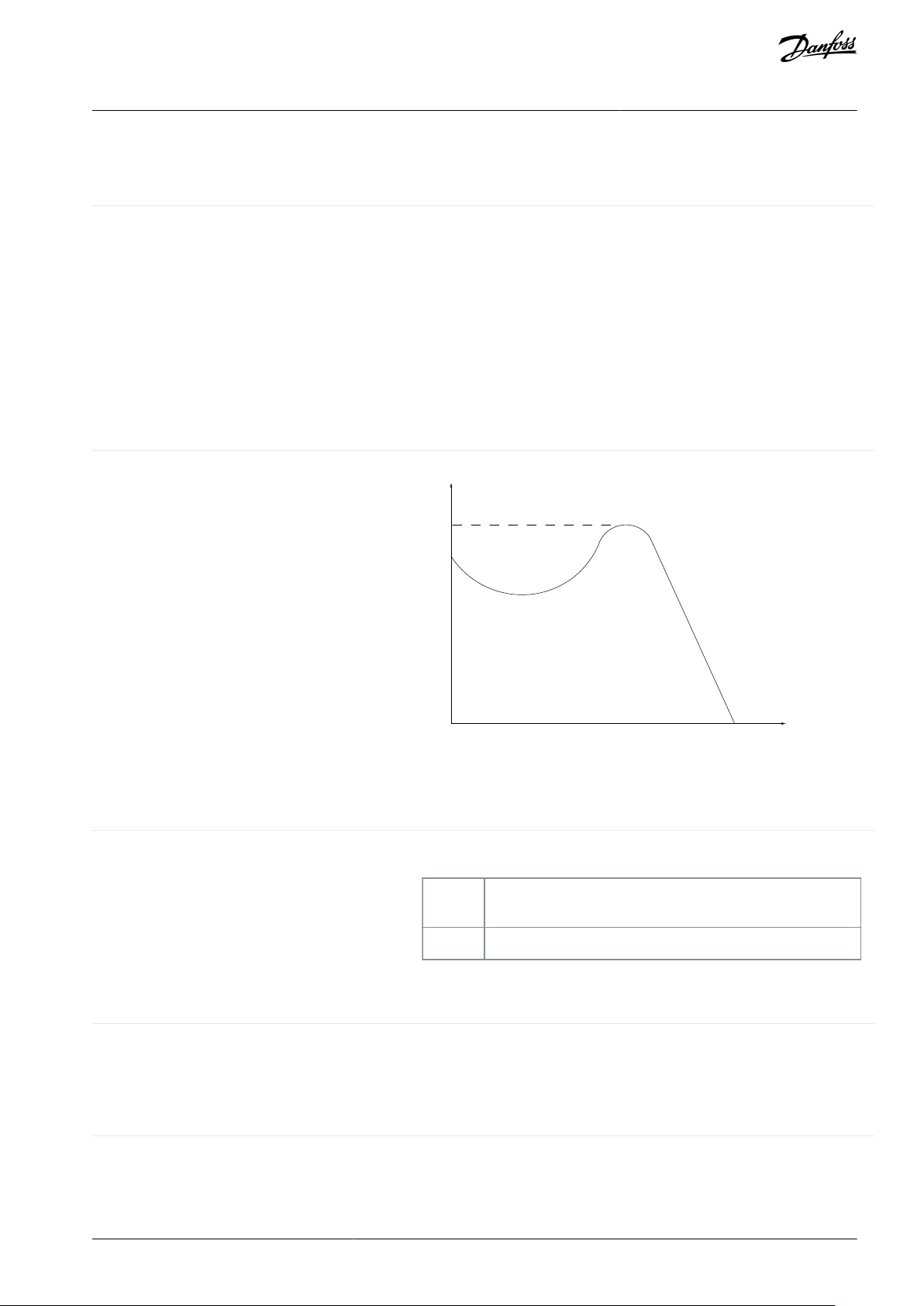
•
•
Analog reference
A signal transmitted to the analog inputs 53 or 54 (voltage or current).
Current input: 0–20 mA and 4–20 mA
Voltage input: 0–10 V DC
Analog inputs
The analog inputs are used for controlling various functions of the drive.
There are 2 types of analog inputs:
Current input, 0–20 mA, and 4–20 mA
Voltage input, 0 V DC to +10 V DC
Analog outputs
The analog outputs can supply a signal of 0–20 mA, 4–20 mA.
Break-away torque
e75za078.10
(1)
(2)
(3)
Bus reference
A signal transmitted to the serial communication port (FC port).
Control command
Functions are divided into 2 groups.
Functions in group 1 have higher priority than functions in group 2.
Group 1
Reset, coast stop, reset and coast stop, quick stop, DC brake,
stop, the [OFF] key.
Group 2
Start, pulse start, reversing, start reversing, jog, freeze output.
Digital inputs
The digital inputs can be used for controlling various functions of the drive.
Digital outputs
The drive features 2 solid-state outputs that can supply a 24 V DC (maximum 40 mA) signal.
fMMotor frequency.
f
M,N
Rated motor frequency (nameplate data).
f
MAX
Maximum compressor frequency.
VLT® Compressor Drive CDS 803
Operating Guide
VLT Drives Glossary - CDS 803
A
B
Glossary
C
D
F
AQ321748767627en-000301/130R0570 | 43Danfoss A/S © 2021.06

f
MIN
Minimum compressor frequency.
f
jog
Motor frequency when the jog function is activated (via digital terminals).
IMMotor current (actual).
I
M,N
Rated motor current (nameplate data).
Intermittent duty cycle
An intermittent duty rating refers to a sequence of duty cycles. Each cycle
consists of an on-load and an off-load period. The operation can be either
periodic duty or non-periodic duty.
lsb
Least significant bit.
MCM
Short for "mille circular mil", an American measuring unit for cable crosssection. 1 MCM=0.5067 mm
2
msb
Most significant bit.
n
M,N
Nominal motor speed (nameplate data).
Online/offline parameters
Changes to online parameters are activated immediately after the data value is changed. Press [OK] to activate changes to off-line parameters.
PI controller
The PI controller maintains the required speed, pressure, temperature, and
so on, by adjusting the output frequency to match the varying load.
P
M,N
Rated motor power (nameplate data in kW or hp).
Power factor
The power factor is the relation between I1 and I
RMS
Powerfactor =
3 ×U × I
1cosϕ
3 ×U × I
RMS
The power factor for 3-phase control:
Powerfactor =
I1 ×cosϕ1
I
RMS
=
I
1
I
RMS
sincecosϕ1 = 1
The power factor indicates to which extent the drive imposes a load on the
mains supply.
The lower the power factor, the higher the I
RMS
for the same kW perform-
ance.
I
RMS
= I
1
2
+ I
5
2
+ I
7
2
+ .. + I
n
2
In addition, a high-power factor indicates that the different harmonic currents are low.
The DC coils in the drive produce a high-power factor, which minimizes the
imposed load on the mains supply.
Preset reference
A defined preset reference to be set from -100% to +100% of the reference
range. Selection of 8 preset references via the digital terminals.
VLT® Compressor Drive CDS 803
Operating Guide
I
L
M
Glossary
N
O
P
AQ321748767627en-000301/130R057044 | Danfoss A/S © 2021.06

RCD
Residual-current device.
Relay outputs
The drive features 2 programmable relay outputs.
Set-up
Save parameter settings in 4 set-ups. Change between the 4 parameter setups and edit 1 set-up, while another set-up is active.
Slip compensation
The drive compensates for the compressor slip by giving the frequency a
supplement that follows the measured compressor load keeping the compressor speed almost constant.
Start-disable command
A stop command belonging to Group 1 control commands, see the table
Function Groups under Control Command.
Stop command
A stop command belonging to Group 1 control commands, see the table
Function Groups under Control Command.
Thermistor
A temperature-dependent resistor placed on the drive or the compressor.
Trip
A state entered in fault situations, for example, if the drive is subject to an
overtemperature or when the drive is protecting the compressor, process,
or mechanism. The drive prevents a restart until the cause of the fault has
disappeared. To cancel the trip state, restart the drive. Do not use the trip
state for personal safety.
Trip lock
The drive enters this state in fault situations to protect itself. The drive requires physical intervention, for example when there is a short circuit on
the output. A trip lock can only be canceled by disconnecting mains, removing the cause of the fault, and reconnecting the drive. Restart is prevented until the trip state is canceled by activating reset or, sometimes, by being programmed to reset automatically. Do not use the trip lock state for
personal safety.
UMInstant motor voltage.
U
M,N
Rated motor voltage (nameplate data).
VT characteristics
Variable torque characteristics used for pumps and fans.
VLT® Compressor Drive CDS 803
Operating Guide
R
S
T
Glossary
U
V
AQ321748767627en-000301/130R0570 | 45Danfoss A/S © 2021.06

Danfoss A/S
Ulsnaes 1
DK-6300 Graasten
vlt-drives.danfoss.com
Danfoss can accept no responsibility for possible errors in catalogs, brochures, and other printed material. Danfoss reserves the right to alter its products without notice. This
also applies to products already on order provided that such alterations can be made without subsequential changes being necessary in specifications already agreed. All
trademarks in this material are property of the respective companies. Danfoss and the Danfoss logotype are trademarks of Danfoss A/S. All rights reserved.
*130R0570*
Danfoss A/S © 2021.06
AQ321748767627en-000301 / 130R0570
*M0020501*
 Loading...