


Design Guide
VLT® Compressor Drive CDS 803
6–30 kW
vlt-drives.danfoss.com


VLT® Compressor Drive CDS 803
Design Guide
Contents
1
Introduction 7
1.1
Purpose of this Design Guide 7
Additional Resources 7
1.2
Supplementary Documentation 7
1.2.1
1.2.2
VLT® Motion Control Tool MCT 10 Software Support 7
1.3
Manual and Software Version 7
1.4
Approvals and Certifications 7
Safety 9
2
Safety Symbols 9
2.1
Qualified Personnel 9
2.2
Safety Precautions 9
2.3
3
Product Overview 11
Contents
3.1
VLT® Compressor Drive CDS 803 Family Overview 11
3.2
VLT® Compressor Drive CDS 803 Features 12
3.2.1
Compressor Features 12
3.2.1.1
3.2.1.2
3.2.1.3
3.2.1.4
3.2.1.5
3.2.1.6
3.2.1.7
3.2.2
Application Features 16
3.2.2.1
3.2.2.2
3.2.2.3
3.2.2.4
3.2.2.5
Secure Start-up 12
Compressor Minimum Speed Detection 13
Short-cycle Protection 14
Anti-reverse Protection 14
Oil Return Management 15
Data Readouts and Commissioning 15
Undersized Compressor 16
Automatic Motor Adaptation (AMA) 16
Motor Thermal Protection 16
Built-in PID Controller 17
Automatic Restart 17
Flying Start 17
3.2.2.6
3.2.2.7
3.2.2.8
3.2.2.9
3.2.2.9.1
3.2.2.9.2
3.3
VLT® Compressor Drive CDS 803 Protections 19
Frequency Bypass 17
Motor Preheat 17
Programmable Set-ups 18
Smart Logic Control (SLC) 18
Comparators 19
Logic Rules 19
AJ330233902305en-000201/130R0596 | 3Danfoss A/S © 2021.05

VLT® Compressor Drive CDS 803
Design Guide
3.3.1
3.3.2
3.3.3
3.3.4
Contents
Mains Input Protection 19
3.3.1.1
3.3.1.2
Output Protection 20
3.3.2.1
3.3.2.2
3.3.2.3
3.3.2.4
3.3.2.5
Temperature Protection 21
3.3.3.1
3.3.3.2
3.3.3.3
Internal Protection 21
Mains Supply Failure, Momentary Dropouts, and Surges 19
Missing Mains Phase Detection 20
Short-circuit Protection (Phase-to-phase) 20
Ground Fault Protection (Output Phase-to-Ground) 20
Locked Rotor Detection 20
Output Phase Loss Detection 20
Overload Protection 20
Minimum and Maximum Temperature Protection 21
Automatic Temperature Derating 21
Temperature-controlled Fans 21
3.3.4.1
3.3.4.2
3.4
Ecodesign for Power Drive Systems 21
3.4.1
Losses in Mains Cabling 23
3.4.2
Input Filters: Line Reactors and Harmonic Filters 23
3.4.3
Drive, Input Side 24
3.4.4
DC Link 24
3.4.5
Drive, Output Side 25
3.4.6
Motor Cables and Motor 26
4
Specifications 27
4.1
Electrical Data 27
4.1.1
Electrical Data 3x200–240 V AC 27
4.1.2
Electrical Data 3x380–480 V AC 27
4.2
Mains Supply (L1, L2, L3) 28
4.3
Compressor Output (U, V, W) 28
4.4
Control Input/Output 29
DC Overvoltage Protection 21
Internal Faults 21
4.4.1
10 V DC Output 29
4.4.2
24 V DC Output 29
4.4.3
Analog Inputs 29
4.4.4
Analog Outputs 29
4.4.5
Digital Inputs 29
4.4.6
Digital Outputs 30
4.4.7
Relay Outputs, Enclosure Sizes H3–H5 30
AJ330233902305en-000201/130R05964 | Danfoss A/S © 2021.05

VLT® Compressor Drive CDS 803
Design Guide
4.4.8
Relay Outputs, Enclosure Size H6 30
4.4.9
RS485 Serial Communication 31
4.5
Ambient Conditions 31
4.6
Conforming Standards 32
4.7
Cable Lengths and Cross-sections 32
4.8
Acoustic Noise 32
4.9
Mechanical Dimensions 33
4.9.1
Drive Dimensions 33
4.9.2
Shipping Dimensions 34
4.10
dU/dt 34
5
Mechanical Installation Considerations 36
5.1
Safe Transportation and Storage 36
5.1.1
Reforming the Capacitors 36
5.2
Side-by-side Installation 37
Contents
5.3
Operating Environment 37
5.3.1
Gases 38
5.3.2
Dust 38
5.3.3
Air Humidity 39
5.3.4
Vibration and Shock 39
5.3.5
Derating for Ambient Temperature and Switching Frequency 39
5.3.5.1
5.3.5.2
5.3.5.3
5.3.6
Derating for Low Air Pressure and High Altitudes 41
5.4
IP21/NEMA Type 1 Enclosure Kit 41
5.5
Acoustic Noise or Vibration 43
5.6
Recommended Disposal 43
6
Electrical Installation Considerations 45
6.1
Electrical Installation in General 45
6.1.1
Fastener Torque Ratings 45
Derating Curves, 6.0, 7.5, and 10 kW 39
Derating Curves, 18.5–22 kW 40
Derating Curves, 30 kW 40
6.2
Fuses and Circuit Breakers 45
6.2.1
Recommendation of Fuses and Circuit Breakers 45
6.3
Electrical Wiring 46
6.3.1
Wiring Schematic 46
6.3.2
Terminal Overview of Enclosure Sizes H3–H5 47
6.3.3
Terminal Overview of Enclosure Size H6 48
6.3.4
Connecting to Mains and Compressor Terminals 48
AJ330233902305en-000201/130R0596 | 5Danfoss A/S © 2021.05

VLT® Compressor Drive CDS 803
Design Guide
6.3.5
6.3.6
6.4
Setting Up RS485 Serial Communication 51
6.5
Electromagnetic Compatibility 52
6.5.1
6.5.2
6.5.3
6.5.4
6.5.5
6.5.6
6.5.7
6.5.8
6.6
Harmonics Emission 61
Contents
6.3.4.1
Relay Terminals 49
Control Terminals 50
EMC Emission Test Results 53
Emission Requirements 53
Immunity Requirements 54
EMC Compatibility 56
EMC-compliant Electrical Installation 57
EMC-compliant Cables 59
Shielded Control Cables 60
RFI Filter Switch 61
IT Grid Installations 49
6.6.1
Harmonics Emission Requirements 62
6.6.2
Harmonics Test Results (Emission) 62
6.7
Galvanic Isolation (PELV) 63
6.8
Ground Leakage Current 63
6.8.1
Using a Residual Current Device (RCD) 65
7
How to Order 67
7.1
Drive Configurator 67
7.2
Type Code Description 67
7.3
Accessories and Spare Parts 68
8
Appendix 69
8.1
Abbreviations 69
8.2
Conventions 69
AJ330233902305en-000201/130R05966 | Danfoss A/S © 2021.05
Edition
Remarks
Software version
AJ330233902305, version 0201
Software update for 18–30 kW (25–40 hp) drives.
6.0–10 kW (8–15 hp): Version 2.0
18–30 kW (25–40 hp): Version 61.20
Description
Conformity mark
EU/EC Declaration of Conformity (EC/CE - European Conformity/Conformité Européenne)
Low Voltage Directive/Electromagnetic compatibility (EMC)/Restriction of Hazardous Substances
(RoHS)
Countries of use: Europe
ACMA Declaration of Conformity (RCM - Regulatory Compliance Mark)
Australian Communications Media Authority (ACMA)
Low Voltage Directive/Electromagnetic compatibility (EMC)
Countries of use: Australia and New Zealand
VLT® Compressor Drive CDS 803
Design Guide
Introduction
1 Introduction
1.1 Purpose of this Design Guide
This Design Guide is intended for qualified personnel, such as:
•
Project and systems engineers.
•
Design consultants.
•
Application and product specialists.
The Design Guide provides technical information to understand the capabilities of the VLT® Compressor Drive CDS 803 for integration into motor control and monitoring systems. Its purpose is to provide design considerations and planning data for integration of
the drive into a system. It caters for selection of drives and options for a diversity of applications and installations. Reviewing the
detailed product information in the design stage enables developing a well-conceived system with optimal functionality and efficiency.
This manual is targeted at a worldwide audience. Therefore, wherever occurring, both SI and imperial units are shown.
VLT® is a registered trademark for Danfoss A/S.
1.2 Additional Resources
1.2.1 Supplementary Documentation
Various resources are available to understand advanced drive operation, programming, and directives compliance.
•
The Programming Guide provides information on how to program and includes complete parameter descriptions.
•
The Operating Guide provides detailed information about installation and commissioning of the drive.
See www.danfoss.com for supplementary documentation.
1.2.2 VLT® Motion Control Tool MCT 10 Software Support
Download the software from the Service and Support download page on www.danfoss.com.
During the installation process of the software, enter CD-key 34544400 to activate the CDS 803 functionality. An activation key is not
required for using the CDS 803 functionality.
The latest software does not always contain the latest updates for the drive. Contact the local sales office for the latest drive updates
(in the form of *.upd files), or download the drive updates from the Service and Support download page on www.danfoss.com.
1.3 Manual and Software Version
This manual is regularly reviewed and updated. All suggestions for improvement are welcome.
Table 1: Manual and Software Version
1.4 Approvals and Certifications
AJ330233902305en-000201 / 130R0596 | 7Danfoss A/S © 2021.05
Description
Conformity mark
VIT-SEPRO Declaration of Conformity (VIT - All-Union Institute of Transformer Engineering)
Low Voltage Directive/Electromagnetic compatibility (EMC)
Country of use: Ukraine
089
Moroccan Declaration of Conformity (CMIM - Moroccan Conformity Mark)
Low Voltage Directive/Electromagnetic compatibility (EMC)
Country of use: Morocco
Eurasian Economic Union Declaration of Conformity (EAC - Eurasian Conformity Mark)
Customs Union Technical Regulations (CU TR)
Low voltage Directive/Electromagnetic compatibility (EMC)/Restriction of Hazardous Substances Direc-
tive (RoHS)
Countries of use: Eurasian Economic Union (Russia, Belarus, Kazakhstan, Armenia, and Kirghizstan)
Certification of Compliance UL listed (UL - Underwriters Laboratories)
Safety organization
Countries of use: USA and Canada
Certification of Compliance UL recognized (UL - Underwriters Laboratories)
Safety organization
Countries of use: USA and Canada
VLT® Compressor Drive CDS 803
Design Guide
Introduction
N O T I C E
The VLT® Compressor Drive CDS 803 with SXXX in the type code is certified against UL 508C. Example:
CDS803P7K5T4E20H4XXCXXXSXXXXAXBXCXXXXDX
The VLT® Compressor Drive CDS 803 with S096 in the type code is certified against UL/EN/IEC 60730-1. Example:
CDS803P30KT4E20H2XXXXXXS096XAXBXCXXXXDX
AJ330233902305en-000201 / 130R05968 | Danfoss A/S © 2021.05

VLT® Compressor Drive CDS 803
Design Guide
2 Safety
2.1 Safety Symbols
The following symbols are used in this manual:
D A N G E R
Indicates a hazardous situation which, if not avoided, will result in death or serious injury.
W A R N I N G
Indicates a hazardous situation which, if not avoided, could result in death or serious injury.
C A U T I O N
Indicates a hazardous situation which, if not avoided, could result in minor or moderate injury.
N O T I C E
Indicates information considered important, but not hazard-related (for example, messages relating to property damage).
Safety
2.2 Qualified Personnel
To allow trouble-free and safe operation of the unit, only qualified personnel with proven skills are allowed to transport, store, assemble, install, program, commission, maintain, and decommission this equipment.
Persons with proven skills:
•
Are qualified electrical engineers, or persons who have received training from qualified electrical engineers and are suitably
experienced to operate devices, systems, plant, and machinery in accordance with pertinent laws and regulations.
•
Are familiar with the basic regulations concerning health and safety/accident prevention.
•
Have read and understood the safety guidelines given in all manuals provided with the unit, especially the instructions given in
the Operating Guide.
•
Have good knowledge of the generic and specialist standards applicable to the specific application.
2.3 Safety Precautions
W A R N I N G
HAZARDOUS VOLTAGE
AC drives contain hazardous voltage when connected to the AC mains or connected on the DC terminals. Failure to perform
installation, start-up, and maintenance by skilled personnel can result in death or serious injury.
Only skilled personnel must perform installation, start-up, and maintenance.
-
W A R N I N G
UNINTENDED START
When the drive is connected to AC mains, DC supply, or load sharing, the motor may start at any time. Unintended start during
programming, service, or repair work can result in death, serious injury, or property damage. Start the motor with an external
switch, a fieldbus command, an input reference signal from the local control panel (LCP), via remote operation using MCT 10
software, or after a cleared fault condition.
Disconnect the drive from the mains.
-
Press [Off/Reset] on the LCP before programming parameters.
-
Ensure that the drive is fully wired and assembled when it is connected to AC mains, DC supply, or load sharing.
-
AJ330233902305en-000201 / 130R0596 | 9Danfoss A/S © 2021.05

Voltage [V]
Power range [kW (hp)]
Minimum waiting time (minutes)
3x200
6.0–10 (8.0–15)
15
3x400
6.0–7.5 (8.0–10)
4
3x400
10–30 (15–40)
15
VLT® Compressor Drive CDS 803
Design Guide
Safety
W A R N I N G
DISCHARGE TIME
The drive contains DC-link capacitors, which can remain charged even when the drive is not powered. High voltage can be
present even when the warning indicator lights are off.
Failure to wait the specified time after power has been removed before performing service or repair work could result in death or
serious injury.
Stop the motor.
-
Disconnect AC mains, permanent magnet type motors, and remote DC-link supplies, including battery back-ups, UPS, and
-
DC-link connections to other drives.
Wait for the capacitors to discharge fully. The minimum waiting time is specified in the table Discharge time and is also visible
-
on the nameplate on the top of the drive.
Before performing any service or repair work, use an appropriate voltage measuring device to make sure that the capacitors
-
are fully discharged.
Table 2: Discharge Time
W A R N I N G
LEAKAGE CURRENT HAZARD
Leakage currents exceed 3.5 mA. Failure to ground the drive properly can result in death or serious injury.
Ensure that the minimum size of the ground conductor complies with the local safety regulations for high touch current
-
equipment.
W A R N I N G
EQUIPMENT HAZARD
Contact with rotating shafts and electrical equipment can result in death or serious injury.
Ensure that only trained and qualified personnel perform installation, start-up, and maintenance.
-
Ensure that electrical work conforms to national and local electrical codes.
-
Follow the procedures in this manual.
-
C A U T I O N
INTERNAL FAILURE HAZARD
An internal failure in the drive can result in serious injury when the drive is not properly closed.
Ensure that all safety covers are in place and securely fastened before applying power.
-
AJ330233902305en-000201 / 130R059610 | Danfoss A/S © 2021.05

e30bj117.10
VLT® Compressor Drive CDS 803
Design Guide
Product Overview
3 Product Overview
3.1 VLT® Compressor Drive CDS 803 Family Overview
Danfoss offers CDS drives in different-sized enclosures with power ratings from 6.0–30 kW (8.0–40 hp). Common for all drives are
the following:
•
I/Os
-
4 digital inputs (PNP or NPN)
-
2 digital outputs
-
2 analog inputs (voltage or current)
-
2 analog outputs
-
2 relay outputs
•
RS485 serial communication
-
Danfoss FC protocol and VLT® Motion Control Tool MCT 10 support
-
Modbus RTU
The drive is a free-standing, wall-mountable, or cabinet-mountable drive available in different ratings to fit various applications. The
complete overview is listed in Table 3.
Illustration 1: VLT® Compressor Drive CDS 803 Family
AJ330233902305en-000201 / 130R0596 | 11Danfoss A/S © 2021.05

•••
•••
Power [kW]
P6K0
P7K5
P10K
P18K
P22K
P30K
Electrical
Mains voltage [V]
3x200–240
3x380–480
3x200–240
3x380–480
3x200–240
3x380–480
3x380–480
3x380–480
3x380–480
Typical shaft output [hp]
8.010152530
40
Mechanical
Enclosure size
H4H3H4H3H5H4H5H5H6
IP protection rating
(1)
IP20
IP20
IP20
IP20
IP20
IP20
Compliance
RFI filter
H4 RFI filter
EN 55011 A1
EN/IEC 61800-3 C2
H2 RFI filter
EN 55011 A2
EN/IEC 61800-3 C3
UL rating
UL Listed
UL 508C
UL Recognized
UL 60730-1
VLT® Compressor Drive CDS 803
Design Guide
Table 3: Overview of VLT® Compressor Drive CDS 803 Family
Product Overview
1
All CDS 803 drives can be upgraded to IP21/NEMA Type 1 with an IP21/NEMA Type 1 Conversion Kit.
3.2 VLT® Compressor Drive CDS 803 Features
Various application functions are programmed in the drive for enhanced system performance. The functions require minimum programming or setup. For activation of the functions, refer to the VLT® Compressor Drive CDS 803 Programming Guide listed in 1.2
Additional Resources.
3.2.1 Compressor Features
The VLT® Compressor Drive CDS 803 offers various specialized functions for use in combination with compressor systems.
3.2.1.1 Secure Start-up
To ensure that the compressor ramps fast to the defined start speed, the VLT® Compressor Drive CDS 803 always runs a start-up
sequence. The compressor runs at the start speed for a defined fixed time.
•
If a locked rotor or flooded compressor occurs, it is detected during start-up.
•
If the drive fails to start the compressor, it trips on Alarm 18, Start failed.
AJ330233902305en-000201 / 130R059612 | Danfoss A/S © 2021.05

Speed
Speed
Start
speed
Start-up sequence
Time
Time
Compressor
start minimum
speed
A18, Start
failed
Compressor start
maximum time to trip
e30bj077.10
e30bj078.10
Speed
Motor speed
low limit
Compressor
minimum
speed for trip
Minimum
speed
detection
timer start
VLT® Compressor Drive CDS 803
Design Guide
Product Overview
Illustration 2: Compressor Start-up Sequence
3.2.1.2 Compressor Minimum Speed Detection
To avoid a malfunction inside the compressor due to missing or low lubrication the VLT® Compressor Drive CDS 803 protects the
compressor if the speed drops below the minimum speed detection limit for too long.
•
In case of excessive low speed the drive issues Alarm 49, Speed limit.
Illustration 3: Minimum Speed Detection
AJ330233902305en-000201 / 130R0596 | 13Danfoss A/S © 2021.05
e30bj250.10
Speed
Start signal
On
Off
Time
Time
Interval between
Starts expires
Warning 96
“Start Delay”
e30bj251.10
Speed
Start signal
On
Off
Time
Time
Minimum run time expired
Warning 97
“Stop Delay”
VLT® Compressor Drive CDS 803
Design Guide
Product Overview
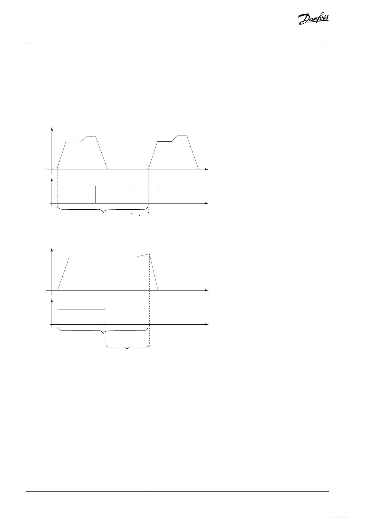
3.2.1.3 Short-cycle Protection
The VLT® Compressor Drive CDS 803 includes a compressor short-cycling protection that prevents mechanical wear to the compressor and reduces the risk of oil shortage caused by starting and stopping too often. The short-cycle protection consists of 2 timers:
•
The interval between starts ensures that a new start first becomes active when the start time has expired.
•
The minimum run time ensures that the compressor always runs for a defined minimum time before stopping the compressor.
•
Warning 96, Start Delay is shown in the display if there is a start signal and the INTERVAL BETWEEN STARTS has not expired.
•
Warning 97, Stop Delay is shown in the display if there is a stop signal and the MINIMUM RUNTIME has not expired.
Illustration 4: Short Cycle Protection, Start Delay
Illustration 5: Short Cycle Protection, Stop Delay
3.2.1.4 Anti-reverse Protection
The anti-reverse protection function prevents the compressor scroll set from running in the wrong direction during stop.
AJ330233902305en-000201 / 130R059614 | Danfoss A/S © 2021.05

e30bj079.10
Speed
Time
Anti-reverse
protection
e30bj080.10
ORM boost speed
ORM boost time
ORM Min
speed limit
Decrease ORM
timer
Increase ORM
timer
Increase ORM
timer
ORM low speed running time expire
ORM timer reset
ORM low speed running time starts Time
VLT® Compressor Drive CDS 803
Design Guide
Illustration 6: Anti-reverse Protection
Product Overview
3.2.1.5 Oil Return Management
The oil return management (ORM) function helps retrieve oil trapped in the cooling system by ramping up periodically (oil boost
speed).
•
The ORM becomes active when the compressor has run below the ORM minimum speed limit for a given time defined by ORM
running time.
•
When ORM is active, the speed increases to a predefined ORM boost speed for a given time defined by ORM boost time
•
Additional a fixed boost interval timer shall trigger the ORM function in case no ORM has run within the defined ORM interval.
Illustration 7: Oil Return Management
3.2.1.6 Data Readouts and Commissioning
The VLT® Motion Control Tool MCT 10 supports the VLT® Compressor Drive CDS 803. The MCT is an efficient tool, for example for
readouts and commissioning.
VLT® Motion Control Tool MCT 10 supports the following readouts:
•
Readouts of alarms, warnings, and fault log in 1 view.
•
Compare a saved project with an online drive.
•
Scope & logging: Easy problem analysis.
•
Offline commissioning.
•
Save/send/mail projects anywhere.
•
Multiple drives in project file. Enables the service organization to be more efficient.
•
Compressor readout of frequency in RPS.
AJ330233902305en-000201 / 130R0596 | 15Danfoss A/S © 2021.05

e30bj082.10
VLT® Compressor Drive CDS 803
Design Guide
Product Overview
3.2.1.7 Undersized Compressor
Programmable compressor choices allow downscaling of a drive to operate with an undersized compressor or running an oversized
drive under extreme conditions. This functionality is useful in applications which are outside the specified appliance area:
•
High ambient temperature installations.
•
High altitude installations.
N O T I C E
UL 60730-1 certification restricts for only allowing 1 dedicated compressor combination and does not offer the ability to run an
undersized compressor.
3.2.2 Application Features
The VLT® Compressor Drive CDS 803 offers custom application functions for enhanced performance.
3.2.2.1 Automatic Motor Adaptation (AMA)
Automatic motor adaptation (AMA) is an automated test procedure used to measure the electrical characteristics of the motor. AMA
provides an accurate electronic model of the motor, allowing the drive to calculate optimal performance and efficiency. Running
the AMA procedure also maximizes the automatic energy optimization feature of the drive.
AMA is performed without the motor rotating and without uncoupling the load from the motor.
N O T I C E
Automatic motor adaptation (AMA) is not required when used with a VZH Danfoss compressor.
3.2.2.2 Motor Thermal Protection
Motor thermal protection can be provided via:
•
Mechanical thermal switch (Klixon type) on a DI.
•
Built-in electronic relay (ETR).
AJ330233902305en-000201 / 130R059616 | Danfoss A/S © 2021.05
1.21.0 1.4
30
10
20
100
60
40
50
1.81.6 2.0
2000
500
200
400
300
1000
600
t [s]
e75za052.13
I
M,N
(parameter 1-24)
I
M
f
OUT
= 2 x f
M,N
(parameter 1-23)
f
OUT
= 1 x f
M,N
f
OUT
= 0.2 x f
M,N
VLT® Compressor Drive CDS 803
Design Guide
Product Overview
N O T I C E
Electronic thermal protection (ETR) is used in combination with a VZH Danfoss compressor.
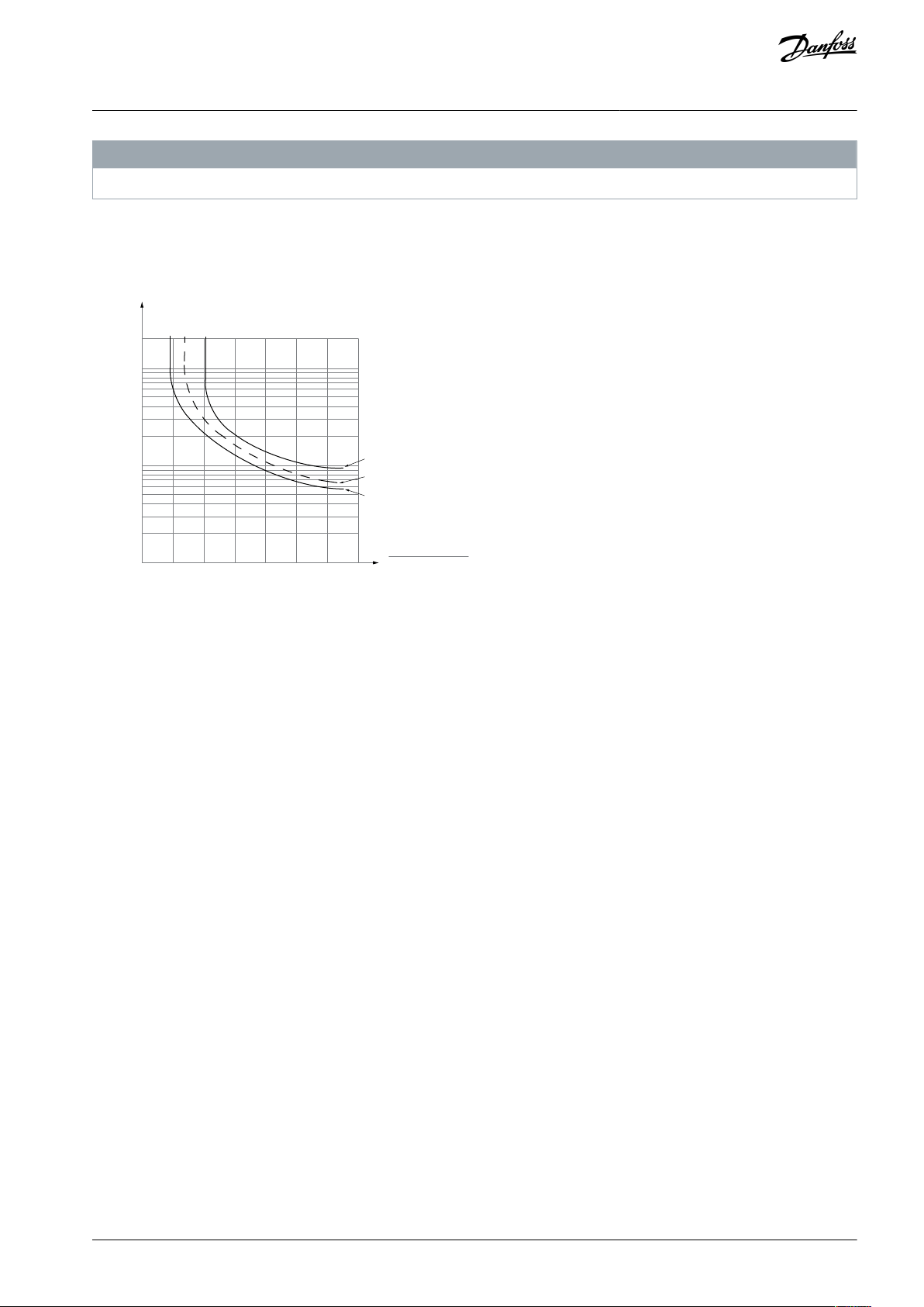
ETR calculates motor temperature by measuring current, frequency, and operating time. The drive shows the thermal load on the
motor in percentage and can issue a warning at a programmable overload setpoint. Programmable options at the overload allow
the drive to stop the motor, reduce output, or ignore the condition. Even at low speeds, the drive meets I2t Class 20 electronic
motor overload standards.
Illustration 8: ETR Characteristics
The X-axis shows the ratio between I
motor
and I
nominal. The Y-axis shows the time in seconds before the ETR cuts off and trips
motor
the drive. The curves show the characteristic nominal speed at twice the nominal speed and at 0.2 x the nominal speed. At lower
speed, the ETR cuts off at lower heat due to less cooling of the motor. In that way, the motor is protected from being overheated
even at low speed. The ETR feature calculates the motor temperature based on actual current and speed. The calculated temperature is visible as a readout parameter in parameter 16-18 Motor Thermal.
3.2.2.3 Built-in PID Controller
The built-in proportional, integral, derivative (PID) controller eliminates the need for auxiliary control devices. The PID controller
maintains constant control of closed-loop systems where regulated pressure, flow, temperature, or other system requirements must
be maintained.
The drive can use 2 feedback signals from 2 different devices, allowing the system to be regulated with different feedback requirements. The drive makes control decisions by comparing the 2 signals to optimize system performance.
3.2.2.4 Automatic Restart
The drive can be programmed to restart the motor automatically after a minor trip, such as momentary power loss or fluctuation.
This feature eliminates the need for manual resetting and enhances automated operation for remotely controlled systems. The
number of restart attempts and the duration between attempts can be limited.
3.2.2.5 Flying Start
Flying start allows the drive to synchronize with an operating motor rotating at up to full speed in either direction. This prevents
trips due to overcurrent draw. It minimizes mechanical stress to the system since the motor receives no abrupt change in speed
when the drive starts.
3.2.2.6 Frequency Bypass
In some applications, the system can have operational speeds that create a mechanical resonance. This mechanical resonance can
generate excessive noise and possibly damage mechanical components in the system. The drive has 4 programmable bypass-frequency bandwidths (parameters 4-60 to 4-63). The bandwidths allow the motor to step over speeds that induce system resonance.
3.2.2.7 Motor Preheat
Instead of using a space heater, Danfoss provides motor preheat functionality. To preheat a motor in a cold or damp environment, a
small amount of DC current can be trickled continuously into the motor to protect it from condensation and cold starts.
AJ330233902305en-000201 / 130R0596 | 17Danfoss A/S © 2021.05

. . .
. . .
Par. 13-11
Comparator Operator
Par. 13-43
Logic Rule Operator 2
Par. 13-51
SL Controller Event
Par. 13-52
SL Controller Action
e30bb671.13
Coast
Start timer
Set Do X low
Select set-up 2
. . .
Running
Warning
Torque limit
Digital input X 30/2
. . .
=
TRUE longer than..
. . .
. . .
VLT® Compressor Drive CDS 803
Design Guide
Product Overview
3.2.2.8 Programmable Set-ups
The drive has 2 setups that can be independently programmed. Using multi-setup, it is possible to switch between independently
programmed functions activated by digital inputs or a serial command. Independent set-ups are used, for example, to change references, or for day/night or summer/winter operation, or to control multiple motors. The LCP shows the active setup.
Setup data can be copied from drive to drive by downloading the information from the removable LCP or by using VLT® Motion
Control Tool MCT 10.
3.2.2.9 Smart Logic Control (SLC)
Smart logic control (SLC) is a sequence of user-defined actions (see parameter 13-52 SL Controller Action [x]) executed by the SLC
when the associated user-defined event (see parameter 13-51 SL Controller Event [x]) is evaluated as TRUE by the SLC.
The condition for an event can be a particular status, or that the output from a logic rule or a comparator operand becomes TRUE.
The condition leads to an associated action as shown in
Illustration 9.
Illustration 9: SLC Event and Action
Events and actions are each numbered and linked in pairs (states), which means that when event [0] is fulfilled (attains the value
TRUE), action [0] is executed. After the 1st action is executed, the conditions of the next event are evaluated. If this event is evaluated
as true, then the corresponding action is executed. Only 1 event is evaluated at any time. If an event is evaluated as false, nothing
happens in the SLC during the current scan interval and no other events are evaluated. When the SLC starts, it only evaluates event
[0] during each scan interval. Only when event [0] is evaluated as true, the SLC executes action [0] and starts evaluating the next
event. It is possible to program 1–20 events and actions.
When the last event/action has been executed, the sequence starts over again from event [0]/action [0]. An example with 4 events/
actions is shown in Illustration 10:
AJ330233902305en-000201 / 130R059618 | Danfoss A/S © 2021.05

e30ba062.15
State 1
13-51.0
13-52.0
State 2
13-51.1
13-52.1
Start
event P13-01
State 3
13-51.2
13-52.2
State 4
13-51.3
13-52.3
Stop
event P13-02
Stop
event P13-02
Stop
event P13-02
Par. 13-11
Comparator Operator
=
TRUE longer than.
. . .
. . .
Par. 13-10
Comparator Operand
Par. 13-12
Comparator Value
e30bb672.10
. . .
. . .
. . .
. . .
Par. 13-43
Logic Rule Operator 2
Par. 13-41
Logic Rule Operator 1
Par. 13-40
Logic Rule Boolean 1
Par. 13-42
Logic Rule Boolean 2
Par. 13-44
Logic Rule Boolean 3
e30bb673.10
VLT® Compressor Drive CDS 803
Design Guide
Product Overview
Illustration 10: Order of Execution when 4 Events/Actions are Programmed
3.2.2.9.1 Comparators
Comparators are used for comparing continuous variables (output frequency, output current, analog input, and so on) to fixed preset values.
Illustration 11: Comparators
3.2.2.9.2 Logic Rules
Combine up to 3 boolean inputs (TRUE/FALSE inputs) from timers, comparators, digital inputs, status bits, and events using the
logical operators AND, OR, and NOT.
Illustration 12: Logic Rules
3.3 VLT® Compressor Drive CDS 803 Protections
The drive has a range of built-in protection functions to protect itself and the compressor during operation. For details of any required setup, in particular compressor parameters, refer to the VLT® Compressor Drive CDS 803 Programming Guide listed in 1.2
Additional Resources for parameter details and programming.
3.3.1 Mains Input Protection
The VLT® Compressor Drive CDS 803 offers various built-in input protections for the 3-phase power terminals L1, L2, and L3.
3.3.1.1 Mains Supply Failure, Momentary Dropouts, and Surges
During a mains dropout, the drive keeps running until the internal DC-link voltage drops below the minimum stop level, which is
typically around 15% or more below the lowest rated supply voltage of the drive. The mains voltage before the dropout and the
motor load determine how long it takes for the drive to coast.
AJ330233902305en-000201 / 130R0596 | 19Danfoss A/S © 2021.05

VLT® Compressor Drive CDS 803
Design Guide
The drive withstands mains fluctuations such as:
•
Transients
•
Momentary dropouts
•
Short voltage drops
•
Surges
The drive automatically compensates for input voltages ±10% from the mains nominal to provide full rated output current. With
auto restart selected, the drive automatically powers up after a voltage trip. With flying start parameterization, the drive can synchronize to a motor spinning freely after a mains dropout and bring it back to normal operation.
Product Overview
3.3.1.2 Missing Mains Phase Detection
The drive monitors the mains input and reacts according to the programmed configuration if improper conditions, such as missing
or detecting too high imbalance between the input phases.
Operation under severe mains imbalance conditions reduces the lifetime of the drive. Conditions are considered severe if the motor
is operated continously near nominal load. The default setting issues a warning, but automated derating of the load can also be
parameterized among multiple choices.
3.3.2 Output Protection
The VLT® Compressor Drive CDS 803 offers various built-in protection features for the compressor terminals U, V, and W.
3.3.2.1 Short-circuit Protection (Phase-to-phase)
The drive is protected against short circuits on the output side by current measurements. A short circuit between 2 output phases
causes an overcurrent internally and turns off all outputs once the short-circuit current exceeds the maximum limit. A drive that
works correctly limits the current it can draw from the supply. Still, it is recommended to use fuses and/or circuit breakers on the
supply side as protection if there is a component breakdown inside the drive (1st fault). Mains side fuses are mandatory for UL compliance.
N O T I C E
To ensure compliance with IEC 60364 for CE or NEC 2017 for UL, it is mandatory to use fuses and/or circuit breakers.
3.3.2.2 Ground Fault Protection (Output Phase-to-Ground)
The drive is protected against ground faults on all output terminals, U, V, and W.
3.3.2.3 Locked Rotor Detection
Sometimes the rotor is locked because of excessive load or other factors preventing the compressor from rotating.
The drive detects the locked rotor situation and trips accordingly to prevent overheating the compressor and the drive.
N O T I C E
In regulation with UL 60730-1 certified products, the locked rotor detection cannot be disabled.
3.3.2.4 Output Phase Loss Detection
The drive monitors all outputs to detect any missing or interrupted connections. If no currents are drawn on any output, it is assumed that no motor is connected and will cause this event to be triggered. If a single phase is lost, an output phase missing event
is triggered. In both scenarios all outputs are turned off. The missing output phase function is enabled by default to avoid motor
damage. Disabling this protection is possible via parameterization.
N O T I C E
In regulation with UL 60730-1 certified products, the output phase loss detection cannot be disabled.
3.3.2.5 Overload Protection
If excessive current outputs or high temperatures are observed for an unwanted period, the protections trip the drive and turn all
the outputs off. The time before the drive trips is controlled by parameterization of the monitored protections.
Voltage limit
The inverter turns off to self-protect the internal components when the maximum voltage limits are reached.
AJ330233902305en-000201 / 130R059620 | Danfoss A/S © 2021.05

VLT® Compressor Drive CDS 803
Design Guide
Output current limit
The inverter turns off to self-protect the internal components when the maximum current limits are reached.
Overtemperature
The inverter turns off to self-protect the internal components when the maximum temperature limits are reached.
Electronic thermal relay (ETR)
ETR is an electronic feature that simulates a bimetal relay based on internal measurements. See also 3.2.2.2 Motor Thermal Protec-
tion.
Product Overview
N O T I C E
In regulation wih UL 60730-1 certified products, the output overload conditions, such as motor overload (ETR), cannot be disa-
bled.
3.3.3 Temperature Protection
The VLT® Compressor Drive CDS 803 offers various built-in temperature protection features for monitoring the operation environment.
3.3.3.1 Minimum and Maximum Temperature Protection
The drive has built-in temperature sensors and reacts immediately to critical temperature limits. At low temperature, a warning will
be triggered. If high temperature limits are exceeded, the drive trips on an alarm and turns off all outputs.
3.3.3.2 Automatic Temperature Derating
Automatic temperature derating can be enabled via parameterization to allow continued operation during high temperatures.
3.3.3.3 Temperature-controlled Fans
Sensors in the drive regulate the operation of the internal cooling fans. Often, the cooling fans do not run during low-load operation, when in sleep mode, or in standby. The sensors reduce noise, increase efficiency, and extend the operating life of the fan.
3.3.4 Internal Protection
The VLT® Compressor Drive CDS 803 offers various built-in internal protection features ensuring that the drive is fully operational.
3.3.4.1 DC Overvoltage Protection
The internal DC-link voltage is increased when the motor acts as a generator. This occurs in the following situations:
•
The load drives the motor (at constant output frequency from the drive), that is, the load generates energy.
•
During deceleration (ramp-down) if the moment inertia is high, the friction is low, and the ramp-down time is too short for the
energy to be dissipated as a loss in the drive, the motor, and the installation.
•
Incorrect slip compensation setting may cause higher DC-link voltage.
•
Back EMF from PM motor operation. If coasted at high RPM, the PM motor back EMF may potentially exceed the maximum
voltage tolerance of the drive and cause damage. To prevent this, the maximum output frequency is automatically limited
based on an internal calculation. This calculation is based on motor parameterizations.
Monitoring of the internal voltage ensures that the drive trips when the DC-link voltage is too high. The drive turns off the output to
protect itself when a certain voltage level is reached. Enabling overvoltage control (OVC) reduces the risk of the drive tripping due
to an overvoltage on the DC link. This is controlled by automatically extending the ramp-down time.
3.3.4.2 Internal Faults
The drive has various internal self-monitoring functions which ensure that the drive is fully operational. For warning and alarm details, refer to VLT® Compressor Drive CDS 803 Programming Guide listed in 1.2 Additional Resources.
3.4 Ecodesign for Power Drive Systems
The Ecodesign Directive is the legislative framework that sets requirements on all energy-related products in the domestic, commercial, and industrial sectors throughout Europe.
The Ecodesign requirements are only mandatory within the European Union. These requirements are like the legislative requirements for energy-related products which apply in North America and Australia.
Terms like Complete Drive Module (CDM) and Power Drive Systems (PDS) are used to define the elements in the design. The objective is to make more efficient and fewer energy consuming designs.
AJ330233902305en-000201 / 130R0596 | 21Danfoss A/S © 2021.05

Mains &
cabling
Transmis-
sion
Load-
Machine
Driven Equipment
Extended Product
Motor System
Vollständiges Antriebsgerät (CDM)
Motor Starter
(Contactor, Softstarter,…)
Motor control equipment = CDM or starter
Feeding
section
Auxiliaries
Basic
Drive
Module
(BDM)
Complete Drive Module (CDM)
Power Drive System (PDS)
e30bu372.10
Relative torque
producing current
Relative
motor stator
frequency
100 %
50 %
25 %
0 %
0 % 50 % 90 %
e30bu373.10
VLT® Compressor Drive CDS 803
Design Guide
Product Overview
The CDM contains the drive controller as well as auxiliary devices and input components.
Illustration 13: Drive System Design
The efficiency classes IE0 to IE2 of the drive controller as specified in IEC 61800-9-2 (EN 50598-2) refer to the 90/100 operating point,
i.e. 90 % motor stator frequency and 100% torque current (see Illustration 14).
Illustration 14: Operating Point according to IEC 61800-9-2 (EN 50598)
Since in the future all component manufacturers will disclose their loss data according to this new standard, optimized applications
can be designed with a wide range of different components. The new Standard allows an accurate preliminary calculation of the
power losses, so that the ROI (Return of Investment) can be reliably determined. Up to now the overall efficiency of speed-regulated
electric motors was estimated with the aid of approximate energy consumption calculations.
It is now possible to determine the total losses of a system for the 8 operating points defined in the standard, including the part
load operation, via a simple addition of power losses. Danfoss helps its customers to avoid having to rely on system solution providers, to ensure that their systems will retain a competitive advantage also in the future.
EC 61800-9-2 (EN 50598-2) shifts the focus from the individual component to the efficiency of the whole drive system. The new
efficiency classes (International Efficiency for Systems, IES)
allow a simple determination of the total losses for a whole drive system (PDS).
Danfoss offers the MyDrive® ecoSmart™ tool, which is available online or as a Smartphone app to assist with the efficiency calcula-
tion. Use MyDrive® ecoSmart™ to:
Look up part load data as defined in IEC 61800-9-2, for VLT® and VACON® drives
•
Calculate efficiency class and part load efficiency for drives and power drive systems
•
Create a report documenting part load loss data and IE or IES efficiency class.
•
For more information, refer to
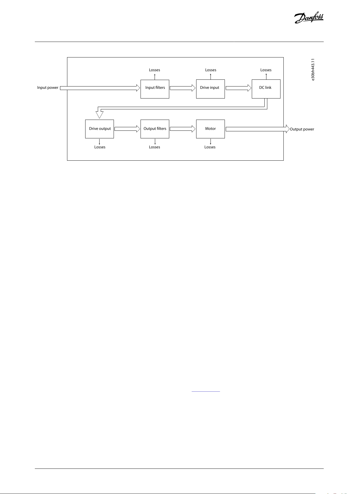
Refer to Illustration 15 to see the components in the PDS which contribute to losses in the design. Mains cables and the load ma-
chine are not a part of the PDS, even though their losses can be significant and could be a part of the evaluation of the overall
energy efficiency of the installation.
http://ecosmart.danfoss.com.
AJ330233902305en-000201 / 130R059622 | Danfoss A/S © 2021.05
Input power
e30bh443.11
Output power
Input filters
Drive input
DC link
Drive output
Output filters
Motor
Losses
Losses
Losses
Losses
Losses
Losses
VLT® Compressor Drive CDS 803
Design Guide
Illustration 15: Losses in a Power Drive System
Product Overview
3.4.1 Losses in Mains Cabling
The cabling from the supply must be considered, as the selection of suitable cables is often a problem, especially when dedicated
feeding transformers are installed. From the impedance of the cables, the energy losses are created in the ohmic part. Calculate the
active power losses for a 3-phase system with a star point groundingas follows:
P
= 3 x R x I
L,mains
Because the load, when using drives and motors, also include reactive power and harmonic currents, these parameters also contribute to losses. The ratio between active and apparent power is normally called the power factor. Having a PDS with a power factor
close to 1 result in the lowest losses in the mains. Using filters on the input side of the drive can lower the power factor.
2
L1
3.4.2 Input Filters: Line Reactors and Harmonic Filters
Line reactor
A line reactor is an inductor which is wired in series between a power source and a load. Line reactors, also called input AC reactors,
are typically used in motor drive applications.
The main function of the line reactor lies into its current limiting characteristics. Line reactors also reduce the main harmonics, limit
the inrush currents, and protect drives and motors. An overall improvement of the true power factor and the quality of the input
current waveform can be achieved.
Line reactors are classified by their percent impedance (denoted as percent IZ or %IZ), which is the voltage drop due to impedance,
at the rated current, expressed as a percent of rated voltage. The most common line reactors have either 3% or 5% impedance.
When to use line reactors
It is important to consider the installation environment for the drives. In some situations, distortion from the grid can damage the
drive and precautions must be taken.
A simple menas of prevention is to ensure a minimum of impedance in front of the drive.
When calculating the impedance, the contribution from the supply transformer and the supply cables is also a part of the circuit. In
specific cases, an additional transformer or reactor is recommended. If the conditions listed exist, consider adding impedance (line
reactor or transformer) in front of the drive:
•
The installation site has switched power factor correction capacitors.
•
The installation site has lightening strikes or voltage spikes.
•
The installation site has power interruptions or voltage dips.
Danfoss offers the line reactor program VLT® Line Reactor MCC 103, see
Harmonic filters
The purpose of using harmonic filters is to reduce the distortion on the mains. The distortion is generated by the drives when
switching the voltage to generate a frequency on the output. The harmonics should be limited both seen from energy consumption
perspective and disturbance of other users in the grid.
There are 2 categories of harmonic solutions:
•
Passive.
•
Active.
Passive solutions consist of capacitors, inductors, or a combination of both in different arrangements. The simplest solution is to add
inductors/reactors of typically 3–5% in front of the drive. This added inductance reduces the number of harmonic currents pro-
Danfoss.com.
AJ330233902305en-000201 / 130R0596 | 23Danfoss A/S © 2021.05

VLT® Compressor Drive CDS 803
Design Guide
duced by the drive. More advanced passive solutions combine capacitors and inductors in trap arrangement specially tuned to
eliminate harmonics starting from, for example, the 5th harmonic.
For more details on the Danfoss passive solutions, refer to VLT® Advanced Harmonic Filters AHF 005/AHF 010 Design Guide.
The active solutions determine the exact current that cancels the harmonics present in the circuit and synthesizes and injects that
current into the system. Thus, the active solution mitigates the real-time harmonic disturbances, which makes these solutions effective at any load profile.
For more details on the Danfoss active solutions, refer to VLT® Low Harmonic Drive Operating Instructions, and VLT® Advanced Active Filter AAF 006 Operating Instructions.
Product Overview
3.4.3 Drive, Input Side
RFI (radio frequency interference)
Drives generate radio frequency interference (RFI) due to their variable-width current pulses. Drives and motor cables radiate these
components and conduct them into the mains system.
RFI filters are used to reduce this interference on the mains according to IEC 61800-3 in order not to disturb radio services. Maximum allowed emission depends on the environment where the PDS is used.
The need for reducing the interferences and the losses created by the coils is a trade-off that is hard to influence in the use of drives.
Even though the losses exist, it is important to fulfill the legislation demands for the installation environment.
RFI filter on IT grid
If the drive is supplied from an isolated mains source (IT mains, floating delta) or TT/TN-S mains with grounded leg (grounded delta),
the RFI filter must be turned off.
In the OFF position, the internal capacitors between the chassis (ground), the input RFI filter, and the DC link are cut off. As the RFI
switch is turned off, the drive is not able to meet optimum EMC performance.
By opening the RFI filter switch, the ground leakage currents are also reduced, but not the high-frequency leakage currents caused
by the switching frequency of the drive. It is important to use isolation monitors that are designed for use with power electronics
(IEC 61557-8). For example, Deif type SIMQ, Bender type IRDH 275/375, or similar.
The Danfoss VLT® drives can be ordered with different types of RFI filters. See more details on RFI, the use of RFI filters, and EMC
compliance in 6.5 Electromagnetic Compatibility.
Passive diode rectifier input
The use of diode rectifiers on the input side of the drives are the most cost-effective design. The energy flow goes from the mains to
the load and have low losses. On the other hand, diodes create harmonics in the mains when rectifying and thereby create losses.
These harmonics can be reduced by having DC-link coils, which are used in the Danfoss VLT® drives.
An energy flow from the drive back to the grid is not possible with this design as the energy is generated back from the application
to the DC link. Use a DC chopper and a connected resistor to absorb the energy. This reduces the energy efficiency significantly.
3.4.4 DC Link
The DC link is a power storage facility for the output section of the drive. There are 2 major components to the DC-link section:
•
Capacitors
•
Coils
In Illustration 16 only 1 capacitor is shown, but it is always a series of capacitors.
AJ330233902305en-000201 / 130R059624 | Danfoss A/S © 2021.05

1
3
+
+
2 4
e30bh114.10
1
Direct current (AC ripple)
2
Rectifier
3
Direct current
4
Inverter
VLT® Compressor Drive CDS 803
Design Guide
Illustration 16: Wiring Diagram of the DC Link
Product Overview
With Danfoss VLT® drives, this intermediate section always uses DC coils, also known as DC line reactors or DC chokes. For cost considerations, most other drive manufacturers do not offer these DC line reactors as standard equipment. Danfoss regards these coils
as essential for 2 main reasons:
•
The ability to reduce harmonic noise (interference) by 40%.
•
The ability to ride through a temporary loss of power. This allows the drive to avoid numerous unplanned shutdowns.
3.4.5 Drive, Output Side
The output side of the drive contains IGBTs used for generating a variable AC voltage with variable frequency. If no filters are used,
overvoltage spikes, due to reflection of the voltage waveform, can be measured on the motor connection. This situation is often
linked with long motor cables used in the installation and can reach values up to twice the level of the DC-link voltage.
From a user perspective, losses on the output side of the drive can be influenced by using a lower switching frequency, but this also
contributes to higher losses in the motor and filters installed. To optimize energy efficiency, a compromise must be found when
selecting the components used, for example, filters, motor type, and others. Often, output filters are used with the purpose of reducing stress on the insulation.
In the following sections, the aspect of different filter types is discussed in perspective of energy efficiency versus function.
Common-mode filters
Common-mode HF filters are placed between the drive and the motor. They are nanocrystaline cores that mitigate high-frequency
noise in the motor cable (shielded or unshielded) and eliminate bearing currents, and hence Electro Discharge Machining (EDM) or
bearing etching in the motor. Bearing currents caused by drives are also referred to as common-mode currents.
Since the common-mode filters mitigate high frequency, these filters absorb energy and contribute also to losses. Here, the tradeoff is the advantage described compared with the losses.
More information on VLT® Common Mode Filters MCC 105 can be found on www.Danfoss.com.
dU/dt filters
At the IGBTs on the output switch, the voltage is not a clean sinus curve. It contains fast changes in voltage levels over a very short
time. The use of dU/dt filters increases the raise time of the motor voltage to reduce the stress on the motor insulation. If not avoided, the problem will typically not show at once, but after some time, the insulation breaks and creates problems.
The switching frequency influences the losses in the dU/dt filters. These losses can be up to 1% of the rated power. Here, the tradeoff is the possible damage of the motor over time compared with the cost of energy losses.
Danfoss offers the VLT® dU/dt Filter MCC 102 as a possible solution. Find more information on www.Danfoss.com.
Sine-wave filters
A more advanced, but also more costly solution, is using sine-wave filters.
The VLT® Sine-Wave Filter MCC 101 is a differential-mode low-pass filter that suppresses the switching frequency component com-
ing from the drive and smoothes out the phase-to-phase voltage of the drive to become sinusoidal. This reduces the motor insula-
AJ330233902305en-000201 / 130R0596 | 25Danfoss A/S © 2021.05

VLT® Compressor Drive CDS 803
Design Guide
tion stress and bearing currents. By supplying the motor with a sinusoidal voltage waveform, the switching acoustic noise from the
motor is also eliminated.
For more detailed information, see the VLT® Sine-Wave Filter MCC 101 factsheet.
However, this type of filter also produces a voltage drop and there may be a reduction in the available control bandwidth. This can
sometimes make it impossible to use this filter type. Again, as for the dU/dt filter, losses are linked to the switching frequency.
For more detailed information, see the VLT® Output Filters Design Guide.
Product Overview
3.4.6 Motor Cables and Motor
Motor cables
Motor cables introduce mainly ohmic losses: the longer the cables, the more resistance. In general, when correctly selected, the
losses in cables shorter than 25 m (82 ft) can be neglected. In single-wire cables with individual shielding, current causes losses in
the cable shielding. These losses can be neglected when using 3-wire cables.
Motor
There are many different types of motors that can be operated with a drive. The solution for dealing with losses in motors is therefore depending on the individual motor type and installation. In standard IEC 61800-9-2:2017 annex D, a discussion on motor load
and losses is found.
A method to evaluate the losses generated in the motor operated with a drive can be found in the standards IEC 60034-2-1 and IEC
TS 60034-2-4.
AJ330233902305en-000201 / 130R059626 | Danfoss A/S © 2021.05

P6K0
P7K5
P10K
Typical shaft output [kW]
6.0
7.510Typical shaft output [hp]
8.01015
Enclosure size
H4H4H5
Maximum cable size in terminals (mains, compressor) [mm2 (AWG)]
16 (6)
16 (6)
16 (6)
Output current @ 40 °C (104 °F) ambient temperature
Continuous (3x200–240 V) [A]
222842
Intermittent (3x200–240 V) [A]
24.2
30.8
46.2
Output current @ 50 °C (122 °F) ambient temperature
Continous (3x200–240 V) [A]
19.82333
Intermittent (3x200–240 V) [A]
21.8
25.3
36.3
Maximum input current
Continuous (3x200–240 V) [A]
21
28.341Intermittent (3x200–240 V) [A]
23.1
31.1
45.1
Maximum mains fuses, see 6.2.1 Recommendation of Fuses and Circuit Breakers
Estimated power loss [W], best case/typical
(1)
182/204
229/268
369/386
Weight enclosure protection IP20 [kg (lb)]
7.9 (17.4)
7.9 (17.4)
9.5 (22.9)
Efficiency [%], best case/typical
(2)
97.3/97.1
98.5/97.1
97.2/97.1
P6K0
P7K5
P10K
P18K
P22K
P30K
Typical shaft output [kW]
6.0
7.51018.52230
Typical shaft output [hp]
8.01015253040Enclosure size
H3H3H4H5H5
H6
Maximum cable size in terminals (mains, motor) [mm
2
(AWG)]
4 (10)
4 (10)
16 (6)
16 (6)
16 (6)
35 (2)
VLT® Compressor Drive CDS 803
Design Guide
4 Specifications
4.1 Electrical Data
4.1.1 Electrical Data 3x200–240 V AC
Table 4: 3x200–240 V AC
Specifications
1
Applies to dimensioning of drive cooling. If the switching frequency is higher than the default setting, the power losses may increase. LCP and
typical control card power consumptions are included. For power loss data according to EN 50598-2, refer to Danfoss
2
Efficiency measured at nominal current. For energy efficiency class, see
mart website.
4.1.2 Electrical Data 3x380–480 V AC
Table 5: 3x380–480 V AC
MyDrive® ecoSmart website.
4.6 Conforming Standards. For part load losses, see Danfoss MyDrive® ecoS-
AJ330233902305en-000201 / 130R0596 | 27Danfoss A/S © 2021.05

P6K0
P7K5
P10K
P18K
P22K
P30K
Output current @ 40 °C (104 °F) ambient temperature (45 °C (113 °F) for 30 kW)
Continuous (3x380–440 V) [A]
12
15.523374461
Intermittent (3x380–440 V)[A]
13.2
17.1
25.3
40.7
46.8
67.1
Continuous (3x441–480 V) [A]
111421374461Intermittent (3x441–480 V) [A]
12.1
15.4
23.1
40.7
46.8
67.1
Output current @ 50 °C (122 °F) ambient temperature (52 °C (125 °F) for 18.5–22 kW)
Continuous (3x380–440 V) [A]
10.91420.93744
48.8
Intermittent (3x380–440 V) [A]
12
15.42340.7
46.8
53.7
Continuous (3x441–480 V) [A]
10
12.6
19.13744
41.6
Intermittent (3x441–480 V) [A]
11
13.92140.7
46.8
45.8
Maximum input current
Continuous (3x380–440 V) [A]
11.2
15.1
22.1
35.2
42.657Intermittent (3x380–440 V) [A]
12.3
16.6
24.3
38.7
45.7
62.7
Continuous (3x441–480 V) [A]
9.4
12.6
18.4
34.8
41.5
55.8
Intermittent (3x441–480 V) [A]
10.3
13.9
20.2
38.2
44.2
60.5
Maximum mains fuses, see 6.2.1 Recommendation of Fuses and Circuit Breakers.
Estimated power loss [W], best case/typical
(1)
104/131
159/198
248/274
412/456
475/523
733
Weight enclosure protection rating IP20 [kg (lb)]
4.3 (9.5)
4.5 (9.9)
7.9 (17.4)
9.5 (20.9)
9.5 (20.9)
24.5 (54)
Efficiency [%], best case/typical
(2)
98.4/98
98.2/97.8
98.1/97.9
98.1/97.9
98.1/97.9
97.8
Supply voltage
200–240 V ±10%
Supply voltage
380–480 V ±10%
Supply frequency
50/60 Hz
Maximum imbalance temporary between mains phases
3.0% of rated supply voltage
True power factor (λ)
≥0.9 nominal at rated load
Displacement power factor (cosφ) near unity
(>0.98)
Switching on the input supply L1, L2, L3 (power-ups)
Maximum 2 times/minute
Environment according to EN 60664-1
Overvoltage category III/pollution degree 2
The unit is suitable for use on a circuit capable of delivering not
more than 100000 A
rms
symmetrical Amperes, 240/480 V maxi-
mum.
Output voltage
0–100% of supply voltage
VLT® Compressor Drive CDS 803
Design Guide
Specifications
1
Applies to dimensioning of drive cooling. If the switching frequency is higher than the default setting, the power losses may increase. LCP and
typical control card power consumptions are included. For power loss data according to EN 50598-2, refer to Danfoss
2
Efficiency measured at nominal current. For energy efficiency class, see
mart website.
4.6 Conforming Standards. For part load losses, see Danfoss MyDrive® ecoS-
4.2 Mains Supply (L1, L2, L3)
4.3 Compressor Output (U, V, W)
MyDrive® ecoSmart website.
AJ330233902305en-000201 / 130R059628 | Danfoss A/S © 2021.05

Output frequency
0–200 Hz (VVC+), 0–400 Hz (u/f)
Switching on output
Unlimited
Ramp times
0.05–3600 s
Terminal number
50
Output voltage
10.5 V ±0.5 V
Maximum load
25 mA
Terminal number
12
Maximum load
80 mA
Number of analog inputs
2
Terminal number
53, 54
Terminal 53 mode
Parameter 6-61 Terminal 53 Setting: 1=voltage, 0=current
Terminal 54 mode
Parameter 6-63 Terminal 54 Setting: 1=voltage, 0=current
Voltage level
0–10 V
Input resistance, R
i
Approximately 10 kΩ
Maximum voltage
20 V
Current level
0/4–20 mA (scalable)
Input resistance, R
i
<500 Ω
Maximum current
29 mA
Resolution on analog input
10 bit
Number of programmable analog outputs
2
Terminal number
42, 45
(1)
Current range at analog output
0/4–20 mA
The load resistor to common at analog out
500 Ω
Maximum voltage at analog output
17 V
Accuracy on analog output
Maximum error: 0.4% of full scale
Resolution on analog output
10 bit
Programmable digital inputs
4
Terminal number
18, 19, 27, 29
VLT® Compressor Drive CDS 803
Design Guide
4.4 Control Input/Output
4.4.1 10 V DC Output
The 10 V DC output is galvanically isolated from the supply voltage (PELV) and other high-voltage terminals.
4.4.2 24 V DC Output
The 24 V DC output is galvanically isolated from the supply voltage (PELV) and other high-voltage terminals.
Specifications
4.4.3 Analog Inputs
The analog inputs are galvanically isolated from the supply voltage (PELV) and other high-voltage terminals.
4.4.4 Analog Outputs
1
Terminals 42 and 45 can also be programmed as digital outputs.
The analog outputs are galvanically isolated from the supply voltage (PELV) and other high-voltage terminals.
4.4.5 Digital Inputs
AJ330233902305en-000201 / 130R0596 | 29Danfoss A/S © 2021.05

Logic
PNP or NPN
Voltage level
0–24 V DC
Voltage level, logic 0 PNP
<5 V DC
Voltage level, logic 1 PNP
>10 V DC
Voltage level, logic 0 NPN
>19 V DC
Voltage level, logic 1 NPN
<14 V DC
Maximum voltage on input
28 V DC
Input resistance, R
i
Approximately 4 kΩ
Digital input 29 as thermistor input
Fault: >2.9 kΩ and no fault: <800 Ω
Digital input 29 as pulse input
Maximum frequency 32 kHz push-pull-driven & 5 kHz (O.C.)
Number of digital outputs
2
Terminals 42 and 45
Terminal number
42, 45
(1)
Voltage level at digital output
17 V
Maximum output current at digital output
20 mA
The load resistor at digital output
1 kΩ
Programmable relay output
2
Relay 01 and 02
01–03 (NC), 01–02 (NO), 04–06 (NC), 04–05 (NO)
Maximum terminal load (AC-1)
(1)
on 01–02/04–05 (NO) (Resistive
load)
250 V AC, 3 A
Maximum terminal load (AC-15)
(1)
on 01–02/04–05 (NO) (Induc-
tive load @ cosφ 0.4)
250 V AC, 0.2 A
Maximum terminal load (DC-1)
(1)
on 01–02/04–05 (NO) (Resistive
load)
30 V DC, 2 A
Maximum terminal load (DC-13)
(1)
on 01–02/04–05 (NO) (Induc-
tive load)
24 V DC, 0.1 A
Maximum terminal load (AC-1)
(1)
on 01–03/04–06 (NC) (Resistive
load)
250 V AC, 3 A
Maximum terminal load (AC-15)
(1)
on 01–03/04–06 (NC) (Inductive
load @ cosφ 0.4)
250 V AC, 0.2 A
Maximum terminal load (DC-1)
(1)
on 01–03/04–06 (NC) (Resistive
load)
30 V DC, 2 A
Minimum terminal load on 01–03 (NC), 01–02 (NO)
24 V DC 10 mA, 24 V AC 20 mA
Environment according to EN 60664-1
Overvoltage category III/pollution degree 2
Programmable relay output
2
VLT® Compressor Drive CDS 803
Design Guide
The digital inputs are galvanically isolated from the supply voltage (PELV) and other high-voltage terminals.
4.4.6 Digital Outputs
Specifications
1
Terminals 42 and 45 can also be programmed as analog output.
The digital outputs are galvanically isolated from the supply voltage (PELV) and other high-voltage terminals.
4.4.7 Relay Outputs, Enclosure Sizes H3–H5
1
IEC 60947 parts 4 and 5. Endurance of the relay varies with different load type, switching current, ambient temperature, drive configuration, work-
ing profile, and so forth. Mount a snubber circuit when connecting inductive loads to the relays.
The relay outputs are galvanically isolated from the supply voltage (PELV) and other high-voltage terminals.
4.4.8 Relay Outputs, Enclosure Size H6
AJ330233902305en-000201 / 130R059630 | Danfoss A/S © 2021.05

Relay 01 and 02
01–03 (NC), 01–02 (NO), 04–06 (NC), 04–05 (NO)
Maximum terminal load (AC-1)
(1)
on 04–05 (NO) (Resistive load)
(2)
(3)
400 V AC, 2 A
Maximum terminal load (AC-15)
(1)
on 04–05 (NO) (Inductive load
@ cosφ 0.4)
240 V AC, 0.2 A
Maximum terminal load (DC-1)
(1)
on 04–05 (NO) (Resistive load)
80 V DC, 2 A
Maximum terminal load (DC-13)
(1)
on 04–05 (NO) (Inductive load)
24 V DC, 0.1 A
Maximum terminal load (AC-1)
(1)
on 04–06 (NC) (Resistive load)
240 V AC, 4 A
Maximum terminal load (AC-15)
(1)
on 04–06 (NC) (Inductive load
@ cosφ 0.4)
240 V AC, 0.2 A
Maximum terminal load (DC-1)
(1)
on 04–06 (NC) (Resistive load)
50 V DC, 2 A
Maximum terminal load (DC-13)
(1)
on 04–06 (NC) (Inductive load)
24 V DC, 0.1 A
Minimum terminal load on 01–03 (NC), 01–02 (NO), 04–06 (NC),
04–05 (NO)
24 V DC 10 mA, 24 V AC 20 mA
Environment according to EN 60664-1
Overvoltage category III/pollution degree 2
Terminal number
68 (P, TX+, RX+), 69 (N, TX-, RX-)
Terminal number
61 common for terminals 68 and 69
Enclosure protection rating
IP20
Enclosure kit available
IP21, TYPE 1
Maximum vibration exposure
(1)
1.0 g
Maximum relative humidity
5–95% (IEC 60721-3-3; Class 3K3 (non-condensing) during opera-
tion)
Aggressive environment (IEC 60721-3-3), coated (standard), enclosure sizes H3–H5
Class 3C3
Aggressive environment (IEC 60721-3-3), non-coated enclosure
size H6
Class 3C2
Environmental testing (IEC 60068-2-43 H2S)
10 days
Ambient temperature, enclosure sizes H3–H5 (6–10 kW (8–15 hp))
(2)
50 °C (122 °F)
Ambient temperature, enclosure size H5 (18–22 kW (25–30 hp))
(2)
52 °C (125.6 °F)
Ambient temperature, enclosure size H6 (30 kW (40 hp))
(2)
45 °C (113 °F)
Minimum ambient temperature during full-scale operation
0 °C (32 °F)
Minimum ambient temperature at reduced performance, enclosure sizes H3–H5
-20 °C (-4 °F)
Minimum ambient temperature at reduced performance, enclosure size H6
-10 °C (14 °F)
Temperature during storage/transport
-30 to +65/70 °C (-22 to +149/158°F)
Maximum altitude above sea level without derating
1000 m (3281 ft)
Maximum altitude above sea level with derating
3000 m (9843 ft)
VLT® Compressor Drive CDS 803
Design Guide
1
IEC 60947 parts 4 and 5. Endurance of the relay varies with different load type, switching current, ambient temperature, drive configuration, work-
ing profile, and so forth. Mount a snubber circuit when connecting inductive loads to the relays.
2
Overvoltage Category II.
3
UL applications 250 V AC, 3 A.
Specifications
The relay outputs are galvanically isolated from the supply voltage (PELV) and other high-voltage terminals.
4.4.9 RS485 Serial Communication
The RS485 serial communication outputs are galvanically isolated from the supply voltage (PELV) and other high-voltage terminals.
4.5 Ambient Conditions
AJ330233902305en-000201 / 130R0596 | 31Danfoss A/S © 2021.05

Derating for high altitude, see 5.3.6 Derating for Low Air Pressure
and High Altitudes.
Safety standards
EN/IEC 61800-5-1, UL 508C, EN/IEC/UL 60730-1
EMC standards, Emission
EN 61800-3, EN 61000-6-3/4, EN 55011, IEC 61800-3
EMC standards, Immunity
EN 61800-3, EN 61000-3-12, EN 61000-6-1/2, EN 61000-4-2, EN
61000-4-3, EN 61000-4-4, EN 61000-4-5, EN 61000-4-6
Energy efficiency class
(1)
IE2
Maximum compressor cable length, shielded/armored (EMC-correct installation)
See 6.5.1 EMC Emission Test Results.
Maximum compressor cable length, unshielded/unarmored
50 m (164 ft)
Maximum cross-section to compressor, mains
See 4.1 Electrical Data for more information
Cross-section DC terminals for filter feedback on enclosure size
H3
4 mm2/11 AWG
Cross-section DC terminals for filter feedback on enclosure sizes
H4–H6
16 mm2/6 AWG
Maximum cross-section to control terminals, rigid wire
2.5 mm2/14 AWG
Maximum cross-section to control terminals, flexible wire
2.5 mm2/14 AWG
Minimum cross-section to control terminals
0.05 mm2/30 AWG
VLT® Compressor Drive CDS 803
Design Guide
1
Refer to 5.3.4 Vibration and Shock for more details.
2
Refer to 5.3 Operating Environment.
4.6 Conforming Standards
1
Determined according to EN 50598-2 at:
Rated load.
•
•
90% rated frequency.
•
Switching frequency factory setting.
•
Switching pattern factory setting.
•
For power loss data according to EN 50598-2, refer to Danfoss
Specifications
MyDrive® ecoSmart website.
N O T I C E
The VLT® Compressor Drive CDS 803 with SXXX in the type code is certified against UL 508C. Example:
CDS803P7K5T4E20H4XXCXXXSXXXXAXBXCXXXXDX
The VLT® Compressor Drive CDS 803 with S096 in the type code is certified against UL/EN/IEC 60730-1. Example:
CDS803P30KT4E20H2XXXXXXS096XAXBXCXXXXDX
4.7 Cable Lengths and Cross-sections
4.8 Acoustic Noise
Acoustic noise from the drives comes from 3 sources:
•
DC-link coils
•
Integral fan
•
RFI filter inductor
AJ330233902305en-000201 / 130R059632 | Danfoss A/S © 2021.05

Enclosure
Level [dBA]
(1)
H3
53.8H464H563.7H671.5
e
f
a
e
e
f
a
d
e
A
a
b
B
C
D
e30bf984.10
Enclosure Size
H3H4H5
H6
IP class
IP20
IP20
IP20
IP20
Power [kW (hp)]
3x200–240 V
–
6.0–7.5
(8.0–10)
10 (15)
–
3x380–480 V
6.0–7.5
(8.0–10)
10
(15)
18.5–22
(25–30)
30 (40)
Height [mm (in)]
A
255 (10.0)
296 (11.7)
334 (13.1)
518 (20.4)
A
(1)
329 (13.0)
359 (14.1)
402 (15.8)
595 (23.4)/635 (25), 45 kW
a
240 (9.4)
275 (10.8)
314 (12.4)
495 (19.5)
Width [mm (in)]
B
100 (3.9)
135 (5.3)
150 (5.9)
239 (9.4)
b
74 (2.9)
105 (4.1)
120 (4.7)
200 (7.9)
Depth [mm (in)]
C
206 (8.1)
241 (9.5)
255 (10)
242 (9.5)
Mounting hole [mm (in)]
d
11 (0.43)
12.6 (0.50)
12.6 (0.50)
–
VLT® Compressor Drive CDS 803
Design Guide
Table 6: Typical Values Measured at a Distance of 1 m (3.28 ft) from the Unit
1
The values are measured under the background of 35 dBA noise and the fan running at full speed.
4.9 Mechanical Dimensions
4.9.1 Drive Dimensions
Specifications
Illustration 17: Dimensions
Table 7: Dimensions, Enclosure Sizes H3–H6
AJ330233902305en-000201 / 130R0596 | 33Danfoss A/S © 2021.05

Enclosure Size
H3H4H5
H6
e
5.5 (0.22)
7 (0.28)
7 (0.28)
8.5 (0.33)
f
8.1 (0.32)
8.4 (0.33)
8.5 (0.33)
15 (0.6)
Maximum weight kg (lb)
4.5 (9.9)
7.9 (17.4)
9.5 (20.9)
5.3 (11.7)
Enclosure size
200–240 V AC
[kW (hp)]
380–480 V AC [kW
(hp)]
IP rating
Maximum
weight [kg (lb)]
Height [mm
(in)]
Width [mm
(in)]
Depth [mm
(in)]H3–
6.0–7.5 (8.0–10)
IP20
4.5 (9.9)
280 (11)
155 (6.1)
320 (12.6)
H4
6.0–7.5 (8.0–10)
10 (15)
IP20
7.9 (17.4)
380 (15)
200 (7.9)
315 (12.4)
H5
10 (15)
18.5–22 (25–30)
IP20
9.5 (20.9)
395 (15.6)
233 (9.2)
380 (15)
H6
–
30 (40)
IP20
24.5 (54.0)
850 (33.5)
370 (15.6)
460 (18.1)
Cable length [m (ft)]
AC line voltage [V]
Rise time [μsec]
V
peak
[kV]
dU/dt [kV/μsec]
200 V 6.0 kW (8.0 hp)
5 (16)
240
0.128
0.445
2.781
25 (82)
240
0.224
0.594
2.121
50 (164)
240
0.328
0.596
1.454
200 V 7.5 kW (10 hp)
5 (16)
240
0.18
0.502
2.244
25 (82)
240
0.22
0.598
2.175
50 (164)
240
0.292
0.615
1.678
200 V 10 kW (15 hp)
36 (118)
240
0.176
0.56
2.545
50 (164)
240
0.216
0.599
2.204
400 V 6.0 kW (8.0 hp)
5 (16)
400
0.168
0.81
3.857
25 (82)
400
0.239
1.026
3.434
50 (164)
400
0.328
1.05
2.560
400 V 7.5 kW (10 hp)
5 (16)
400
0.168
0.81
3.857
25 (82)
400
0.239
1.026
3.434
50 (164)
400
0.328
1.05
2.560
400 V 18.5 kW (25 hp)
5 (16)
400
0.132
0.88
5.220
25 (82)
400
0.172
1.026
4.772
VLT® Compressor Drive CDS 803
Design Guide
1
Including decoupling plate.
Specifications
The dimensions are only for the physical units. When installing in an application, allow space above and below the units for cooling.
The amount of space for free air passage is listed in 5.2 Side-by-side Installation.
4.9.2 Shipping Dimensions
Table 8: Shipping Dimensions
4.10 dU/dt
Table 9: dU/dt Data
AJ330233902305en-000201 / 130R059634 | Danfoss A/S © 2021.05

Cable length [m (ft)]
AC line voltage [V]
Rise time [μsec]
V
peak
[kV]
dU/dt [kV/μsec]
50 (164)
400
0.222
1.00
3.603
400 V 22 kW (30 hp)
5 (16)
400
0.132
0.88
5.220
25 (82)
400
0.172
1.026
4.772
50 (164)
400
0.222
1.00
3.603
400 V 30 kW (40 hp)
10 (33)
400
0.376
0.92
1.957
50 (164)
400
0.536
0.97
1.448
100 (328)
400
0.696
0.95
1.092
150 (492)
400
0.8
0.965
0.965
10 (33)
480
0.384
1.2
2.5
50 (164)
480
0.632
1.18
1.494
100 (328)
480
0.712
1.2
1.348
150 (492)
480
0.832
1.17
1.125
10 (33)
500
0.408
1.24
2.431
50 (164)
500
0.592
1.29
1.743
100 (328)
500
0.656
1.28
1.561
150 (492)
500
0.84
1.26
1.2
VLT® Compressor Drive CDS 803
Design Guide
Specifications
AJ330233902305en-000201 / 130R0596 | 35Danfoss A/S © 2021.05

Storage duration
Duration reforming guideline
Under 2 years
No reforming required. Connect to mains voltage.
2–3 years
Connect to mains voltage and wait a minimum of 30 minutes before loading the drive.
Over 3 years
Using a DC supply connected directly to the DC-link terminals of the drive, ramp up the voltage 0–100% of
DC bus voltage in increments of 25%, 50%, 75%, and 100% rated voltage under no load for 30 minutes at
each increment. See Illustration 18 for an illustration of this method.
VLT® Compressor Drive CDS 803
Mechanical Installation
Design Guide
Considerations
5 Mechanical Installation Considerations
5.1 Safe Transportation and Storage
Store the drive in a dry location and keep the equipment sealed in its packaging until installation. Follow all instructions on transportation and storage, and make sure that the ambient conditions are according to the specifications given in 4.5 Ambient Condi-
tions.
•
If the package is kept in storage for more than 2 months, keep it in controlled conditions:
-
Make sure that the temperature variation is low.
-
Make sure that the humidity is <50%.
•
Only use lifting and handling equipment rated and suitable for the purpose.
-
Check the weight of the drive and lift the drive with a lifting device if needed. In this case, use the lifting eyes/bars designed
for this purpose.
-
Check the center of gravity on the packaging or on the drive before lifting the drive. Avoid tilting the drive to prevent it
from overturning.
•
Keep the drive in its package until it has to be installed. After unpacking, protect the drive from dust, debris, and moisture.
5.1.1 Reforming the Capacitors
For drives that are in storage and do not have voltage applied, maintenance of the capacitors in the drive may be required.
To avoid damage to the internal DC-link capacitors, reforming is required if the drive has been stored without applying voltage for
more than 3 years. Reforming is possible only with drives with DC terminals. When reforming the capacitors:
•
The reforming voltage must be 1.35–1.45 times the rated mains voltage. If the DC-link voltage stays at a low level and does not
reach approximately 1.41 x mains voltage, contact the local service agent.
•
The supply current draw must not exceed 500 mA.
Table 10: Drive Storage Duration and Reforming Recommendations
AJ330233902305en-000201 / 130R059636 | Danfoss A/S © 2021.05

A
B
100
75
50
25
0.5 1 1.5 2
e30bh757.10
A
Percent of DC voltage
B
Hours
Power [kW (hp)]
Clearance above/below [mm (in)]
Size
IP protection rating
3x200–240 V
3x380–480 V
H3
IP20–6.0–7.5 (8.0–10)
100 (4)
H4
IP20
6.0–7.5 (8.0–10)
10 (15)
100 (4)
H5
IP20
10 (15)
18.5–22 (25–30)
100 (4)
H6
IP20–30(40)
200 (7.9)
VLT® Compressor Drive CDS 803
Design Guide
Mechanical Installation
Considerations
Illustration 18: Percent of DC Voltage Increments and Reforming Time
5.2 Side-by-side Installation
The drive can be mounted side by side but requires the clearance specified in Table 11 above and below for cooling.
Table 11: Clearance Required for Cooling
With IP21/NEMA Type1 option kit mounted, a distance of 50 mm (2 in) between the units is required.
N O T I C E
5.3 Operating Environment
In environments with airborne liquids, particles, or corrosive gases, ensure that the IP/Type rating of the equipment matches the
installation environment.
For specifications regarding ambient conditions, see 4.5 Ambient Conditions.
N O T I C E
CONDENSATION
Moisture can condense on the electronic components and cause short circuits. Avoid installation in areas subject to frost. Install
an optional space heater when the drive is colder than the ambient air. Operating in standby mode reduces the risk of condensa-
tion as long as the power dissipation keeps the circuitry free of moisture.
AJ330233902305en-000201 / 130R0596 | 37Danfoss A/S © 2021.05

Class
3C1
3C2
3C3
Gas type
Unit
Value
Mean value
Maximum value
(1)
Mean value
Maximum value
(1)
Sea salt
n/a
None
Salt mist
Salt mist
Sulfur oxide
mg/m
3
0.1
0.3
1.0
5.010Hydrogen sulfide
mg/m
3
0.01
0.1
0.5
3.010Chlorine
mg/m
3
0.01
0.1
0.3
0.3
1.0
Hydrogen chloride
mg/m
3
0.01
0.1
0.5
1.0
5.0
Hydrogen fluoride
mg/m
3
0.003
0.01
0.03
0.1
2.0
Ammonia
mg/m
3
0.3
1.0
3.01035
Ozone
mg/m
3
0.01
0.05
0.1
0.1
0.3
Nitrogen Oxides
mg/m
3
0.1
0.5
1.0
3.0
9.0
VLT® Compressor Drive CDS 803
Mechanical Installation
Design Guide
Considerations
N O T I C E
EXTREME AMBIENT CONDITIONS
Hot or cold temperatures compromise unit performance and longevity.
Do not operate in environments where the ambient temperature exceeds 55 °C (131 °F).
-
The drive can operate at temperatures down to -10 °C (14 °F). However, proper operation at rated load is only guaranteed at
-
0 °C (32 °F) or higher.
If the temperature exceeds ambient temperature limits, extra air conditioning of the cabinet or installation site is required.
-
5.3.1 Gases
Aggressive gases, such as hydrogen sulfide, chlorine, or ammonia, can damage electrical and mechanical components of a drive.
Contamination of the cooling air can also cause the gradual decomposition of PCB tracks and door seals. Aggressive contaminants
are often present in sewage treatment plants or swimming pools. A clear sign of an aggressive atmosphere is corroded copper.
In aggressive atmospheres, restricted IP enclosures are recommended along with conformal-coated circuit boards.
The electronic components are, as standard, coated as per IEC60721-3-3, class 3C2. For harsh and aggressive environments, coating
as per IEC60721-3-3, class 3C3 is available.
Table 12: Conformal Coating Class Ratings
1
Maximum values are transient peak values and are not to exceed 30 minutes per day.
Refer to 7.1 Drive Configurator for ordering the correct protective rating.
5.3.2 Dust
Installation of drives in environments with high dust exposure is often unavoidable. Consider the following when installing drives in
such environments:
•
Reduced cooling.
•
Cooling fans.
•
Periodic maintenance.
Reduced cooling
Dust forms deposits on the surface of the device and inside on the circuit boards and the electronic components. These deposits act
as insulation layers and hamper heat transfer to the ambient air, reducing the cooling capacity. The components become warmer.
This causes accelerated aging of the electronic components and the service life of the unit decreases. Dust deposits on the heat sink
in the back of the unit also decrease the service life of the unit.
AJ330233902305en-000201 / 130R059638 | Danfoss A/S © 2021.05

fsw[kHz]
20 10
0
10%
20%
30%
40%
50%
60%
70%
80%
90%
100%
110 %
I
out[%]
16
5
e30bh856.10
40
45
50
o
C
o
C
o
C
104
o
F
113
o
F
122
o
F
fsw[kHz]
20 10
0
10%
20%
30%
40%
50%
60%
70%
80%
90%
100%
110%
I
out[%]
16
40
45
50
5
o
C
o
C
o
C
e30bh857.10
VLT® Compressor Drive CDS 803
Mechanical Installation
Design Guide
Cooling fans
The airflow for cooling the unit is produced by cooling fans, usually on the back of the unit. The fan rotors have small bearings into
which dust can penetrate and act as an abrasive. This leads to bearing damage and fan failure.
Periodic maintenance
Under the conditions described above, it is recommended to clean the drive during periodic maintenance. Remove dust from the
heat sink and fans.
Considerations
5.3.3 Air Humidity
The drive has been designed to meet the IEC/EN 60068-2-3 standard, EN 50178 9.4.2.2 at 50 °C (122 °F).
5.3.4 Vibration and Shock
The drive has been tested according to the following standards:
•
IEC/EN 60068-2-6: Vibration (sinusoidal) - 1970
•
IEC/EN 60068-2-64: Vibration, broad-band random
The drive complies with the requirements that exist for units mounted on the walls and floors of production premises, and in panels
bolted to walls or floors.
5.3.5 Derating for Ambient Temperature and Switching Frequency
Ensure that the ambient temperature measured over 24 h is at least 5 °C (9 °F) lower than the maximum ambient temperature that
is specified for the drive. If the drive is operated at high ambient temperature, decrease the constant output current. If the ambient
temperature is higher than 50 °C (122 °F) or the installation by altitude is higher than 1000 m (3281 ft), a larger VLT® Compressor
Drive CDS 803 might be needed to run an undersized compressor. Consult Danfoss for support.
5.3.5.1 Derating Curves, 6.0, 7.5, and 10 kW
Illustration 19: 400 V IP20 H3 6.0–7.5 kW (8.0–10 hp)
Illustration 20: 200 V IP20 H4 6.0–7.5 kW (8.0–10 hp)
AJ330233902305en-000201 / 130R0596 | 39Danfoss A/S © 2021.05

fsw[kHz]
20 10
0
10%
20%
30%
40%
50%
60%
70%
80%
90%
100%
110%
I
out[%]
16
40
45
50
5
o
C
o
C
o
C
e30bh858.10
fsw[kHz]
20 10
0
10%
20%
30%
40%
50%
60%
70%
80%
90%
100%
110%
I
out
[%]
16
40
45
50
5
o
C
o
C
o
C
e30bh859.10
e30bi924.10
0
10
%
20
%
30
%
40
%
50
%
60
%
70
%
80
%
90
%
100
%
110
%
0
2
5
10
16
52 °C
45 °C
40 °C
I
out
[%]
fsw[
kHz
]
VLT® Compressor Drive CDS 803
Design Guide
Illustration 21: 400 V IP20 H4 10 kW (15 hp)
Mechanical Installation
Considerations
Illustration 22: 200 V IP20 H5 10 kW (15 hp)
5.3.5.2 Derating Curves, 18.5–22 kW
Drives in the power range 18.5–22 kW are able to deliver 100% current in ambient temperatures up to 52 °C (125 °F) with a default
switching frequency of 5.0 kHz (f_sw). If the switching frequency is increased, the following derating curves apply.
Illustration 23: 400 V IP20 H5 18.5–22 kW (25–30 hp)
5.3.5.3 Derating Curves, 30 kW
Drives in the power range 30 kW are able to deliver 100% current in ambient temperatures up to 45 °C (113 °F) with a default
switching frequency of 4.0 kHz (f_sw). If the switching frequency is increased, the following derating curves apply.
AJ330233902305en-000201 / 130R059640 | Danfoss A/S © 2021.05

e30bi925.10
0
10%
20%
30%
40%
50%
60%
70%
80%
90%
100 %
110 %
0
2
4
10
6
50 °C
45 °C
40 °C
I
out
[%]
fsw[
kHz
]
8
12
VLT® Compressor Drive CDS 803
Mechanical Installation
Design Guide
Illustration 24: 400 V IP20 H6 30 kW (40 hp)
Considerations
5.3.6 Derating for Low Air Pressure and High Altitudes
The cooling capability of air is decreased at low air pressure. For altitudes above 2000 m (6562 ft), contact Danfoss regarding PELV.
Below 1000 m (3281 ft) altitude, derating is not necessary. For altitudes above 1000 m (3281 ft), decrease the ambient temperature
or the maximum output current. Decrease the output by 1% per 100 m (328 ft) altitude above 1000 m (3281 ft) or reduce the maximum ambient cooling air temperature by 1 °C (1.8 °F) per 200 m (656 ft).
5.4 IP21/NEMA Type 1 Enclosure Kit
If environment, air quality, or surroundings require extra protection, an IP21/NEMA Type 1 kit can be ordered, see 7.3 Accessories
and Spare Parts. The IP21/NEMA Type 1 is an optional enclosure element available for IP20 units. If the enclosure kit is used, an IP20
unit is upgraded to comply with enclosure IP21/NEMA Type 1.
N O T I C E
The IP21/IP21 are not suitable for outdoor mounting.
AJ330233902305en-000201 / 130R0596 | 41Danfoss A/S © 2021.05

e30bb902.12
A
B
C
VLT® Compressor Drive CDS 803
Design Guide
Mechanical Installation
Considerations
Illustration 25: H3–H6
AJ330233902305en-000201 / 130R059642 | Danfoss A/S © 2021.05

e30bb903.10
Enclosure size
Power [kW (hp)]
Height [mm (in)] A
Width [mm (in)] B
Depth [mm (in)] C
3x200-240 V
3x380-480 V
H3–6.0–7.5 (8.0–10)
346 (13.6)
106 (4.2)
210 (8.3)
H4
6.0–7.5 (8.0–10)
10 (14)
374 (14.7)
141 (5.6)
245 (9.6)
H5
10 (14)
18.5–22 (25–30)
418 (16.5)
161 (6.3)
260 (10.2)
H6–30 (40)
663 (26.1)
260 (10.2)
242 (9.5)
VLT® Compressor Drive CDS 803
Design Guide
Mechanical Installation
Considerations
Illustration 26: Dimensions
Table 13: Enclosure Kit Specifications
5.5 Acoustic Noise or Vibration
If the compressor application makes noise or vibrations at certain frequencies, adjust the following parameters to avoid resonance
problems within the system.
•
Upper and lower frequency limits, Parameter group 4-6* Speed Bypass.
•
Switching pattern and switching frequency, parameter group 14-0* Inverter Switching.
5.6 Recommended Disposal
When the AC drive reaches the end of its service life, its primary components can be recycled.
Before the materials can be removed, the drive must be disassembled. Product parts and materials can be dismantled and separa-
ted. Generally, all metals, such as steel, aluminum, copper and its alloys, and precious metals can be recycled as material. Plastics,
AJ330233902305en-000201 / 130R0596 | 43Danfoss A/S © 2021.05

•
•
This symbol on the product indicates that it may not be disposed of as household waste.Do not dispose of equipment
containing electrical components together with domestic waste.
It must be handed over to the applicable take-back scheme for the recycling of electrical and electronic equipment.
Dispose of the product through channels provided for this purpose.
Comply with all local and currently applicable laws and regulations.
VLT® Compressor Drive CDS 803
Mechanical Installation
Design Guide
rubber, and cardboard can be used in energy recovery. Printed circuit boards and large electrolytic capacitors (diameter >2.5 cm)
need further treatment according to IEC 62635 guidelines. To ease recycling, plastic parts are marked with an appropriate identification code.
Contact your local Danfoss office for further information on environmental aspects and recycling instructions for professional recyclers. End of life treatment must follow international and local regulations.
All drives are designed and manufactured in accordance with Danfoss company guidelines on prohibited and restricted substances.
A list of these substances is available at www.danfoss.com.
Considerations
AJ330233902305en-000201 / 130R059644 | Danfoss A/S © 2021.05

Power [kW (hp)]
Torque [Nm (in-lb)]
Enclosure size
IP protection rating
3x200–240 V
3x380–480 V
Mains
Motor
DC connection
Control terminals
Ground
Relay
H3
IP20–6.0–7.5 (8.0–10)
0.8 (7)
0.8 (7)
0.8 (7)
0.5 (4)
0.8 (7)
0.5 (4)
H4
IP20
6.0–7.5 (8.0–
10)
10–15 (15–20)
1.2 (11)
1.2 (11)
1.2 (11)
0.5 (4)
0.8 (7)
0.5 (4)
H5
IP20
10 (15)
18.5–22 (25–30)
1.2 (11)
1.2 (11)
1.2 (11)
0.5 (4)
0.8 (7)
0.5 (4)
H6
IP20–30 (40)
4.5 (40)
4.5 (40)
–
0.5 (4)
3 (27)
0.5 (4)
Circuit breakers
(1)
Fuse
UL
Non-ULULNon-UL
Bussmann
Bussmann
Bussmann
Bussmann
Maximum fuse
Power [kW (hp)]
Type RK5
Type RK1
Type J
Type T
Type gG
3x200–240 V
6.0 (8.0)
–
–
FRS-R-50
KTN-R50
JKS-50
JJN-50
gG-50
7.5 (10)
FRS-R-50
KTN-R50
JKS-50
JJN-50
gG-50
10 (15)
FRS-R-80
KTN-R80
JKS-80
JJN-80
gG-63
3x380–480 V
6.0 (8.0)
–
–
FRS-R-25
KTS-R25
JKS-25
JJS-25
gG-25
7.5 (10)
FRS-R-25
KTS-R25
JKS-25
JJS-25
gG-25
10 (15)
FRS-R-50
KTS-R50
JKS-50
JJS-50
gG-50
VLT® Compressor Drive CDS 803
Electrical Installation
Design Guide
Considerations
6 Electrical Installation Considerations
6.1 Electrical Installation in General
All cabling must comply with national and local regulations on cable cross-sections and ambient temperature. Copper conductors
are required. 75 °C (167 °F) is recommended.
6.1.1 Fastener Torque Ratings
Table 14: Tightening Torques for Enclosure Sizes H3–H6, 3x200–240 V & 3x380–480 V
6.2 Fuses and Circuit Breakers
Fuses and circuit breakers ensure that possible damage to the drive is limited to damage inside the unit. Danfoss recommends fuses
on the supply side as protection. For further information, see the application note Fuses and Circuit Breakers found on www.dan-
foss.com under Service and support/Documentation/Manuals & guides.
N O T I C E
Use of fuses on the supply side is mandatory for IEC 60364 (CE) and NEC 2009 (UL) compliant installations.
6.2.1 Recommendation of Fuses and Circuit Breakers
Table 15: Fuses and Circuit Breakers
AJ330233902305en-000201 / 130R0596 | 45Danfoss A/S © 2021.05

Circuit breakers
(1)
Fuse
UL
Non-ULULNon-UL
Bussmann
Bussmann
Bussmann
Bussmann
Maximum fuse
Power [kW (hp)]
Type RK5
Type RK1
Type J
Type T
Type gG
18.5 (25)
–––
JJS-80
gG-63
22 (30)
JJS-80
gG-63
30 (40)
JJS-125
gG-80
L1
L2
L3
3-phase
power
input
PE
PE
+10 V DC
0-10 V DC-
0-10 V DC-
50 (+10 V OUT)
54 (A IN)
53 (A IN)
55 (COM A IN/OUT)
0/4-20 mA
0/4-20 mA
42 0/4-20 mA A OUT / D OUT
45 0/4-20 mA A OUT / D OUT
18 (D IN)
19 (D IN)
27 (D IN)
29 (
D IN)
12 (+24 V OUT)
24 V (NPN)
20 (COM D IN)
O V (PNP)
24 V (NPN)
O V (PNP)
24 V (NPN)
O V (PNP)
24 V (NPN)
O V (PNP)
Bus ter.
Bus ter.
RS485
Interface
RS485
(N RS485) 69
(P RS485) 68
(Com RS485 ) 61
(PNP)-Source
(NPN)-Sink
ON=Terminated
OFF=Unterminated
ON
1 2
240 V AC 3 A
Not present on all power sizes
Do not connect shield to 61
01
02
03
relay 1
relay 2
UDC+
UDC-
Motor
U
V
W
e30bj246.10
06
05
04
240 V AC 3 A
VLT® Compressor Drive CDS 803
Design Guide
1
Circuit breakers have not been evaluated by Danfoss as part of the certification process.
6.3 Electrical Wiring
6.3.1 Wiring Schematic
Electrical Installation
Considerations
Illustration 27: Basic Wiring Schematic Drawing
AJ330233902305en-000201 / 130R059646 | Danfoss A/S © 2021.05

1
2
2
3
4
U
V
W
-DC
+DC
e30bb634.11
5
MAINS
MOTOR
1
Mains
2
Ground
3
Compressor
4
Relays
5
Control terminals
VLT® Compressor Drive CDS 803
Design Guide
N O T I C E
There is no access to UDC- and UDC+ on the following units:
IP20, 380–480 V, 30 kW (40 hp).
-
6.3.2 Terminal Overview of Enclosure Sizes H3–H5
Electrical Installation
Considerations
Illustration 28: Enclosure Sizes H3–H5
AJ330233902305en-000201 / 130R0596 | 47Danfoss A/S © 2021.05

1
95
99
L1 91 / L2 92 / L3 93
U 96 /
V 97 /
W 98
03 02 01
06 05 04
2
3
4
e30bb762.12
1
Mains
2
Ground
3
Compressor
4
Relays
e30bi968.10
VLT® Compressor Drive CDS 803
Design Guide
6.3.3 Terminal Overview of Enclosure Size H6
Electrical Installation
Considerations
Illustration 29: Enclosure Size H6
6.3.4 Connecting to Mains and Compressor Terminals
•
Tighten all terminals in accordance with the information provided in 6.1.1 Fastener Torque Ratings.
•
Keep the compressor cable as short as possible to reduce the noise level and leakage currents.
•
Use a shielded/armored compressor cable to comply with the EMC emission specifications and connect this cable to both the
decoupling plate and the compressor. Also see 6.5.5 EMC-compliant Electrical Installation.
1.
Connect the ground cable to the ground terminal, then connect the mains supply to terminals L1, L2, and L3.
AJ330233902305en-000201 / 130R059648 | Danfoss A/S © 2021.05

e30bi967.10
Drive terminals
Compressor
UT1VT2W
T3
VLT® Compressor Drive CDS 803
Design Guide
2.
Connect the ground cable to the ground terminal, then connect the compressor to terminals U, V, and W.
Electrical Installation
Considerations
Table 16: Connection of Compressor to Terminals
6.3.4.1 IT Grid Installations
N O T I C E
If the drive is supplied from an isolated mains source or mains with grounded leg, the RFI filter is recommended to be disabled,
see 6.5.8 RFI Filter Switch.
Once disabled, the filter capacitors between the chassis and the DC link are cut off to avoid damage to the DC link and to reduce the
ground capacity currents, according to IEC 61800-3. If optimum EMC performance is required, avoid exceeding overvoltage limits
within the DC bus by making sure that the energy charged into the DC link through the RFI filter is either discharged via loading the
DC bus terminals or output terminals U, V, and W.
It is important to use isolation monitors that are rated for use with power electronics (IEC 61557-8).
C A U T I O N
Ensure that the supply voltage does not exceed 440 V (3x380–480 V units) when connected to an IT mains source.
6.3.5 Relay Terminals
Relay 1
•
Terminal 01: Common.
•
Terminal 02: Normally open.
•
Terminal 03: Normally closed.
AJ330233902305en-000201 / 130R0596 | 49Danfoss A/S © 2021.05

Relay1
Relay2
03
02
01
06
05
04
e30bi798.10
e30bd331.11
VLT® Compressor Drive CDS 803
Design Guide
Relay 2
•
Terminal 04: Common.
•
Terminal 05: Normally open.
•
Terminal 06: Normally closed.
Electrical Installation
Considerations
Illustration 30: Relay Outputs 1 and 2
6.3.6 Control Terminals
Remove the terminal cover to access the control terminals.
Use a flat-edged screwdriver to push down the lock lever of the terminal cover under the LCP, then remove the terminal cover as
shown in the following illustration.
Illustration 31: Removing the Terminal Cover
AJ330233902305en-000201 / 130R059650 | Danfoss A/S © 2021.05

e30bf892.10
12 20 55
181927 29 42 54
45 50 53
DIGI IN
61 68 69
N
P
COMM. GND
+24 V
GND
GND
10 V OUT
10 V/20 mA IN
0/4-20 mA A OUT/DIG OUT
BUS TER.
OFF ON
DIGI IN
DIGI IN
DIGI IN
0/4-20 mA A OUT/DIG OUT
10 V/20 mA IN
VLT® Compressor Drive CDS 803
Electrical Installation
Design Guide
The following illustration shows all the drive control terminals. Applying start (terminal 18), connection between terminals 12-27,
and an analog reference (terminal 53 or 54, and 55) make the drive run.
The digital input mode of terminal 18, 19, 27, and 29 is set in parameter 5-00 Digital Input Mode (PNP is default value).
Considerations
Illustration 32: Control Terminals
6.4 Setting Up RS485 Serial Communication
6.4.1 RS485 Features
RS485 is a 2-wire bus interface compatible with multi-drop network topology. This interface contains the following features:
•
Ability to select from the following communication protocols:
-
FC (default protocol)
-
Modbus RTU
•
Functions can be programmed remotely using the RS485 connection or in parameter group 8-** Communications and Options.
•
A switch (BUS TER) is provided on the control card for bus termination resistance.
N O T I C E
Altering between the supported communication protocols can be accessed and changed via the LCP as parameter 8-30 Protocol is
not available in VLT® Motion Control Tool MCT 10.
6.4.2 Configuring RS485 Serial Communication
Procedure
1.
Connect RS485 serial communication wiring to terminals (P RS485) 68 and (N RS485) 69.
-
Use shielded serial communication cable.
-
Properly ground the wiring. Refer to 6.5.5 EMC-compliant Electrical Installation.
AJ330233902305en-000201 / 130R0596 | 51Danfoss A/S © 2021.05

+
e30bi768.10
RS485
69
GND
68
1
2
z
z
z
L1
L2
L3
PE
U
V
W
C
S
I
2
I
1
I
3
I
4
C
S
C
S
C
S
C
S
I
4
C
S
z
PE
3
4
5
6
e75za062.12
VLT® Compressor Drive CDS 803
Electrical Installation
Design Guide
2.
Configure all required settings such as address, baud rate, and so on in parameter group 8-** Communications and Options.
For more details on parameters, refer to VLT® Compressor Drive CDS 803 Programming Guide listed in 1.2 Additional Re-
sources.
Example
Illustration 33: RS485 Wiring Connection
Considerations
6.5 Electromagnetic Compatibility
Electrical devices both generate interference and are affected by interference from other generated sources. The electromagnetic
compatibility (EMC) of these effects depends on the power and the harmonic characteristics of the devices. Uncontrolled interaction
between electrical devices in a system can degrade compatibility and impair reliable operation. Interference takes the form of the
following:
•
Electrostatic discharges
•
Rapid voltage fluctuations
•
High-frequency interference
Electrical interference is most commonly found at frequencies in the range 150 kHz to 30 MHz. Airborne interference from the drive
system in the range 30 MHz to 1 GHz is generated from the inverter, motor cable, and the motor.
Capacitive currents in the motor cable, coupled with a high dU/dt from the motor voltage, generate leakage currents. See Illustra-
tion 34. Shielded motor cables have higher capacitance between the phase wires and the shield, and again between the shield and
ground. This added cable capacitance, along with other parasitic capacitance and motor inductance, changes the electromagnetic
emission signature produced by the unit. The change in electromagnetic emission signature occurs mainly in emissions less than
5 MHz. Most of the leakage current (I1) is carried back to the unit through the PE (I3), leaving only a small electromagnetic field (I4)
from the shielded motor cable. The shield reduces the radiated interference but increases the low-frequency interference on the
mains.
Illustration 34: Electric Model Showing Possible Leakage Currents
AJ330233902305en-000201 / 130R059652 | Danfoss A/S © 2021.05

1
Ground wire
2
Shield
3
AC mains supply
4
Drive5Shielded motor cable
6
Motor
CSPossible shunt parasitic capacitance paths (varies
with different installations)
I1Common-mode leakage current
I2Shielded motor cable
I3Safety ground (4th conductor in motor cables)
I4Unintended common-mode current
Conduct emission
Maximum shielded cable length [m (ft)]
Radiated emission
EN 55011
Class A Group 2
Industrial environment
Class A Group 1
Industrial environment
Class B
Housing, trades,
and light industries
Class A Group
2
Industrial environment
Class A Group
1
Industrial environment
Class B
Housing,
trades, and
light industries
EN/IEC
61800-3
Category C3
Second environment Industrial
Category C2
First environment
Home and office
Category C1
First environment Home and
office
Category C3
Second environment Industrial
Category C2
First environment Home
and office
Category C1
First environment Home
and office
External
RFI filter
No
YesNoYesNoYesNoYesNoYesNoYes
H4 RFI filter (EN 55011 A1, EN/IEC61800-3 C2)
6.0– 10 kW
(8.0– 15
hp)
––25 (82)
50 (164)
–
20 (66)
––Yes
Yes–No
H2 RFI filter (EN 55011 A2, EN/IEC 61800-3 C3)
18–30 kW
(25– 40
hp)
5 (16.4)
–––––
Yes–No–No
–
VLT® Compressor Drive CDS 803
Electrical Installation
Design Guide
Considerations
6.5.1 EMC Emission Test Results
The following test results have been obtained using a system with a drive, a shielded control cable, a control box with potentiometer, and a shielded motor cable.
Table 17: EMC Emission Test Results
6.5.2 Emission Requirements
According to the EMC product standard for AC drives, EN/IEC 61800-3:2004, the EMC requirements depend on the intended use of
the drive. Four categories are defined in the EMC product standard. The definitions of the 4 categories together with the requirements for mains supply voltage conducted emissions are given in Table 18.
AJ330233902305en-000201 / 130R0596 | 53Danfoss A/S © 2021.05

Category
Definition
Conducted emission requirement according to
the limits given in EN
55011
C1
Drives installed in the 1st environment (home and office) with a supply voltage less than
1000 V.
Class B
C2
Drives installed in the 1st environment (home and office) with a supply voltage less than
1000 V, which are neither plug-in nor movable and are intended for installation and
commissioning by a professional.
Class A Group 1
C3
Drives installed in the 2nd environment (industrial) with a supply voltage lower than
1000 V.
Class A Group 2
C4
Drives installed in the 2nd environment (industrial) with a supply voltage equal to or
above 1000 V or rated current equal to or above 400 A or intended for use in complex
systems.
No limit line. Make an EMC
plan.
Environment
Generic standard
Conducted emission requirement according to the limits
given in EN 55011
1st environment (home and office)
EN/IEC 61000-6-3 Emission standard for residential, commercial, and light industrial environments.
Class B
2nd environment (industrial environment)
EN/IEC 61000-6-4 Emission standard for industrial environments.
Class A Group 1
VLT® Compressor Drive CDS 803
Design Guide
Table 18: Emission Requirements
When the generic emission standards are used, the drives are required to comply with the limits in Table 19.
Electrical Installation
Considerations
Table 19: Emission Limit Classes
N O T I C E
According to the EMC Directive, a system is defined as a combination of several types of equipment, finished products, and/or
components combined, designed and/or put together by the same person (system manufacturer) intended to be placed on the
market for distribution as a single functional unit for an end user and intended to be installed and operated together to perform a
specific task. The EMC Directive applies to products/systems and installations, but in case the installation is built up of CE marked
products/systems the installation can also be considered compliant with the EMC Directive. Installations shall not be CE marked.
According to the EMC Directive, Danfoss Drives as a manufacturer of product/systems is responsible for obtaining the essential
requirements of the EMC Directive and attaching the CE mark. For systems involving load sharing and other DC terminals, Dan-
foss Drives can only ensure compliance to the EMC Directive when end users connect combinations of Danfoss Drives products
as described in our technical documentation.
If any 3rd-party products are connected to the load share or other DC terminals on the AC drives, Danfoss Drives cannot guaran-
tee that the EMC requirements are fulfilled.
6.5.3 Immunity Requirements
The immunity requirements for drives depend on the environment in which they are installed. The requirements for the industrial
environment are higher than the requirements for the home and office environment. All Danfoss VLT® drives comply with the requirements for the industrial environment and therefore also comply with the lower requirements for home and office environment
with a large safety margin.
To document immunity against burst transient from electrical phenomena, the following immunity tests have been carried out on a
system consisting of:
•
A drive (with options if relevant).
•
A shielded control cable.
•
A control box with potentiometer, motor cable, and motor.
AJ330233902305en-000201 / 130R059654 | Danfoss A/S © 2021.05

Basic standard
Burst
IEC 61000-4-4
Surge
IEC 61000-4-5
ESD
IEC 61000-4-2
Radiated electro-
magnetic field
IEC 61000-4-3
RF common mode
voltage
IEC 61000-4-6
Acceptance criterion
BBBAA
Line
4 kV CM
2 kV/2 Ω DM
4 kV/12 Ω CM
––10 V
RMS
Motor
4 kV CM
4 kV/2 Ω
(1)
––10 V
RMS
Brake
4 kV CM
4 kV/2 Ω
(1)
––10 V
RMS
Load sharing
4 kV CM
4 kV/2 Ω
(1)
––10 V
RMS
Control wires
2 kV CM
2 kV/2 Ω
(1)
––10 V
RMS
Standard bus
2 kV CM
2 kV/2 Ω
(1)
––10 V
RMS
Relay wires
2 kV CM
2 kV/2 Ω
(1)
––10 V
RMS
Application and Fieldbus options
Application and network options
2 kV CM
2 kV/2 Ω
(1)
––10 V
RMS
LCP cable
2 kV CM
2 kV/2 Ω
(1)
––10 V
RMS
External 24 V DC
2 kV CM
0.5 kV/2 Ω DM
1 kV/12 Ω CM
––10 V
RMS
Enclosure––
8 kV AD
6 kV CD
10 V/m
–
VLT® Compressor Drive CDS 803
Electrical Installation
Design Guide
The tests were performed in accordance with the following basic standards:
•
EN 61000-4-2 (IEC 61000-4-2) Electrostatic discharges (ESD): Simulation of electrostatic discharges from human beings.
•
EN 61000-4-3 (IEC 61000-4-3) Radiated immunity: Amplitude modulated simulation of the effects of radar and radio communication equipment and mobile communications equipment.
•
EN 61000-4-4 (IEC 61000-4-4) Burst transients: Simulation of interference brought about by switching a contactor, relay, or
similar devices.
•
EN 61000-4-5 (IEC 61000-4-5) Surge transients: Simulation of transients brought about by, for example, lightning that strikes
near installations.
•
EN 61000-4-6 (IEC 61000-4-6) RF Common mode: Simulation of the effect from radio-transmission equipment joined by connection cables.
The immunity requirements should follow product standard IEC 61800-3. See
Table 20: EMC Immunity, Voltage Range: 200–240 V, 380–480 V
Table 20.
Considerations
1
Injection on cable shield.
AD: Air Discharge
CD: Contact Discharge
CM: Common Mode
DM: Differential Mode
AJ330233902305en-000201 / 130R0596 | 55Danfoss A/S © 2021.05

e30bc968.12
1
3
25 4
6
98
M
7
1
Power supply (SMPS) including signal isolation of DC
link2Gate drive for the IGBTs
3
Current transducers
4
Opto-coupler, brake module (optional)
5
Internal inrush, RFI, and temperature measurement
circuits
6
Custom relays
7
Mechanical brake
VLT® Compressor Drive CDS 803
Electrical Installation
Design Guide
Considerations
6.5.4 EMC Compatibility
N O T I C E
OPERATOR RESPONSIBILITY
According to the EN 61800-3 standard for variable-speed drive systems, the operator is responsible for ensuring EMC compliance.
Manufacturers can offer solutions for operation conforming to the standard. Operators are responsible for applying these solu-
tions and for paying the associated costs.
There are 2 options for ensuring electromagnetic compatibility:
•
Eliminate or minimize interference at the source of emitted interference.
•
Increase the immunity to interference in devices affected by its reception.
RFI filters
The goal is to obtain systems that operate stably without radio frequency interference between components. To achieve a high
level of immunity, use drives with high-quality RFI filters.
N O T I C E
In a residential environment, this product can cause radio interference, in which case supplementary mitigation measures may be
required.
PELV and galvanic isolation compliance
All control and relay terminals comply with PELV (excluding grounded delta leg above 400 V). To obtain galvanic (ensured) isolation,
fulfill requirements for higher isolation and provide the relevant creepage/clearance distances. These requirements are described in
EN 61800-5.1.
Electrical isolation is provided as shown in Illustration 35. The components described comply with both PELV and the galvanic isolation requirements.
Illustration 35: Galvanic Isolation
AJ330233902305en-000201 / 130R059656 | Danfoss A/S © 2021.05

VLT® Compressor Drive CDS 803
Electrical Installation
Design Guide
Considerations
6.5.5 EMC-compliant Electrical Installation
To obtain an EMC-compliant installation, be sure to follow all electrical installation instructions.
Also, remember to practice the following:
•
When using relays, control cables, a signal interface, fieldbus, or brake, connect the shield to the enclosure at both ends. If the
ground path has high impedance, is noisy, or is carrying current, break the shield connection on 1 end to avoid ground current
loops.
•
Convey the currents back to the unit using a metal mounting plate. Ensure good electrical contact from the mounting plate by
securely fastening the mounting screws to the drive chassis.
•
Use shielded cables for motor output cables. An alternative is unshielded motor cables within metal conduit.
•
Ensure that motor and brake cables are as short as possible to reduce the interference level from the entire system.
•
Avoid placing cables with a sensitive signal level alongside motor and brake cables.
•
For communication and command/control lines, follow the particular communication protocol standards. For example, USB
must use shielded cables, but RS485/ethernet can use shielded UTP or unshielded UTP cables.
•
Ensure that all control terminal connections are rated protective extra low voltage (PELV).
N O T I C E
TWISTED SHIELD ENDS (PIGTAILS)
Twisted shield ends increase the shield impedance at higher frequencies, which reduces the shield effect and increases the leak-
age current.
Use integrated shield clamps instead of twisted shield ends.
-
N O T I C E
SHIELDED CABLES
If shielded cables or metal conduits are not used, the unit and the installation do not meet regulatory limits on radio frequency
(RF) emission levels.
N O T I C E
EMC INTERFERENCE
Failure to isolate power, motor, and control cables can result in unintended behavior or reduced performance.
Use shielded cables for motor and control wiring.
-
Provide a minimum 200 mm (7.9 in) separation between mains input, motor cables, and control cables.
-
N O T I C E
INSTALLATION AT HIGH ALTITUDE
There is a risk of overvoltage. Isolation between components and critical parts could be insufficient and may not comply with
PELV requirements.
Use external protective devices or galvanic isolation. For installations above 2000 m (6500 ft) altitude, contact Danfoss re-
-
garding protective extra low voltage (PELV) compliance.
N O T I C E
PROTECTIVE EXTRA LOW VOLTAGE (PELV) COMPLIANCE
Prevent electric shock by using PELV electrical supply and complying with local and national PELV regulations.
AJ330233902305en-000201 / 130R0596 | 57Danfoss A/S © 2021.05

L1
L2L3PEL1L2L3PEPEu
v
w
2
1
3
5
IEC 60309
16
17
18
14
12
8
7
10
9
4
11
13
446
15
90
+DC
BR-
B
M
AINS
L1 L2 L3
91 92 93
RELA
Y 1 RELA
Y 2
99
- L
C -
UV
W
MO
T
OR
VLT® Compressor Drive CDS 803
Design Guide
Electrical Installation
Considerations
Illustration 36: Example of Proper EMC Installation
AJ330233902305en-000201 / 130R059658 | Danfoss A/S © 2021.05

1
Programmable logic controller (PLC)
2
Minimum 16 mm2 (6 AWG) equalizing cable
3
Control cables
4
Minimum 200 mm (7.9 in) between control cables,
motor cables, and mains cables
5
Mains supply options, see IEC/EN 61800-5-1
6
Bare (unpainted) surface
7
Star washers
8
Brake cable (shielded) – not shown, but same
gounding principle applies as for motor cable
9
Motor cable (shielded)
10
Mains cable (unshielded)
11
Output contactor
12
Cable insulation stripped
13
Common ground busbar. Follow local and national
requirements for cabinet grounding.
14
Brake resistor
15
Terminal box
16
Connection to motor
17
Motor
18
EMC cable gland
e75za166.14
0.01 0.1 1 10 100
10ˉ²
10ˉ³
10ˉ¹
1
10¹
10²
10⁴
10³
10⁵
1
mΩ/m
MHz
2
3
4
5
6
7
VLT® Compressor Drive CDS 803
Electrical Installation
Design Guide
Considerations
6.5.6 EMC-compliant Cables
To optimize EMC immunity of the control cables and emission from the motor cables, use braided shielded/armored cables.
The ability of a cable to reduce the in- and outgoing radiation of electric noise depends on the transfer impedance (ZT). The shield of
a cable is normally designed to reduce the transfer of electric noise. However, a shield with a lower transfer impedance (ZT) value is
more effective than a shield with a higher transfer impedance (ZT).
Cable manufacturers rarely state the transfer impedance (ZT), but it is often possible to estimate transfer impedance (ZT) by assessing the physical design of the cable.
Transfer impedance (ZT) can be assessed based on the following factors:
•
The conductibility of the shield material.
•
The contact resistance between the individual shield conductors.
•
The shield coverage, that is, the physical area of the cable covered by the shield - often stated as a percentage value.
•
Shield type (braided or twisted).
Illustration 37: Transfer Impedance (ZT)
AJ330233902305en-000201 / 130R0596 | 59Danfoss A/S © 2021.05

1
Aluminum-clad with copper wire.
2
Twisted copper wire or armored steel wire cable.
3
Single-layer braided copper wire with varying percentage shield coverage. This is the typical reference
cable.
4
Double-layer braided copper wire.
5
Twin layer of braided copper wire with a magnetic,
shielded/armored intermediate layer.
6
Cable that runs in copper tube or steel tube.
7
Lead cable with 1.1 mm (0.04 in) wall thickness.
1
2
PE
FC
PE
PLC
e30bb922.12
PE PE
<10 mm
1
Minimum 16 mm2 (6 AWG)
2
Equalizing cable
100nF
FC
PE
PE
PLC
<10 mm
e30bb609.12
PE
FC
PE
FC
e30bb923.12
PE PE
69
68
61
69
68
61
1
2
<10 mm
1
Minimum 16 mm2 (6 AWG)
2
Equalizing cable
VLT® Compressor Drive CDS 803
Electrical Installation
Design Guide
Considerations
6.5.7 Shielded Control Cables
Usually, the preferred method is to secure control and serial communication cables with shielding clamps provided at both ends to
ensure the best possible high frequency cable contact.
If the ground potential between the drive and the PLC is different, electric noise could disturb the entire system. Solve this problem
by fitting an equalizing cable as close as possible to the control cable. Minimum cable cross-section: 16 mm2 (6 AWG).
Illustration 38: Shielding Clamps at Both Ends
6.5.7.1 50/60 Hz Ground Loops
With long control cables, ground loops may occur. To eliminate ground loops, connect 1 end of the shield to the ground with a
100 nF capacitor (keeping leads short).
Illustration 39: Connection with a 100 nF Capacitor
6.5.7.2 Avoid EMC Noise on Serial Communication
This terminal is connected to ground via an internal RC link. Use twisted-pair cables to reduce interference between conductors. The
recommended method is shown in the following illustration.
Illustration 40: Twisted-pair Cables
Alternatively, the connection to terminal 61 can be omitted.
AJ330233902305en-000201 / 130R059660 | Danfoss A/S © 2021.05

PE
FC
PE
FC
e30bb924.12
PE PE
69
69
68
68
1
2
<10 mm
1
Minimum 16 mm2 (6 AWG)
2
Equalizing cable
e30bb612.10
1
1
EMC screw
I1I5I
7
Hz50250
350
e75ha034.10
VLT® Compressor Drive CDS 803
Electrical Installation
Design Guide
Illustration 41: Twisted-pair Cables without Terminal 61
Considerations
6.5.8 RFI Filter Switch
For power sizes 6.0–10 kW (8.0–15 hp), disable the RFI filter by removing the screw.
For power sizes 18.5–22 kW (20–25 hp), removing the screw does not have any electrical effect and does not alter any RFI settings.
For power size 30 kW (40 hp), no options are available for disabling the RFI filter.
If reinserted, use only M3x12 screw.
6.6 Harmonics Emission
A drive takes up a non-sinusoidal current from mains, which increases the input current I
formed with a Fourier analysis and split into sine-wave currents with different frequencies, that is, different harmonic currents I
with 50 Hz basic frequency:
Table 21: Harmonic Currents
The harmonics do not affect the power consumption directly, but increase the heat losses in the installation (transformer, cables).
So, in plants with a high percentage of rectifier load, maintain harmonic currents at a low level to avoid overload of the transformer
and high temperature in the cables.
Illustration 42: DC-link Coils
N O T I C E
. A non-sinusoidal current is trans-
RMS
n
AJ330233902305en-000201 / 130R0596 | 61Danfoss A/S © 2021.05

Options
Definition
1
IEC/EN 61000-3-2 Class A for 3-phase balanced equipment (for professional equipment only up to 1 kW (1.3 hp) total
power).
2
IEC/EN 61000-3-12 Equipment 16–75 A and professional equipment as from 1 kW (1.3 hp) up to 16 A phase current.
Individual harmonic current In/I1 (%)
I5I7I11I
13
Actual 6.0–10 kW (8.0–15 hp), IP20, 200 V (typical)
32.6
16.6
8.0
6.0
Limit for R
sce
≥120
402515
10
Harmonic current distortion factor (%)
THDi
PWHD
Actual 6.0–10 kW (8.0–15 hp), 200 V (typical)
39
41.4
Limit for R
sce
≥120
48
46
Individual harmonic current In/I1 (%)
I5I7I11I
13
Actual 6.0–22 kW (8.0–30 hp), IP20, 380–480 V (typical)
36.7
20.8
7.6
6.4
Limit for R
sce
≥120
402515
10
Harmonic current distortion factor (%)
VLT® Compressor Drive CDS 803
Electrical Installation
Design Guide
Considerations
N O T I C E
Some of the harmonic currents might disturb communication equipment connected to the same transformer or cause resonance
with power factor correction batteries.
To ensure low harmonic currents, the drive is equipped with DC-link coils as standard. This normally reduces the input current I
RMS
by 40%.
The voltage distortion on the mains supply voltage depends on the size of the harmonic currents multiplied by the mains impe-
dance for the frequency in question. The total voltage distortion THDv is calculated based on the individual voltage harmonics using this formula:
THD % = U
+ U
5
2
+ ... + U
7
2
N
2
(UN% of U)
6.6.1 Harmonics Emission Requirements
Equipment is connected to the public supply network.
Table 22: Connected Equipment
6.6.2 Harmonics Test Results (Emission)
Power sizes up to 10 kW (15 hp) [200–240 V AC] comply with IEC/EN 61000-3-12, Table 4. Power sizes up to 30 kW (40 hp) [380–
480 V AC] comply with IEC/EN 61000-3-2 Class A and IEC/EN 61000-3-12, Table 4.
Table 23: Harmonic Current 6.0–10 kW (8.0–15 hp), 200 V
Table 24: Harmonic Current 6.0–22 kW (8.0–30 hp), 380–480 V
AJ330233902305en-000201 / 130R059662 | Danfoss A/S © 2021.05

THDi
PWHD
Actual 6.0–22 kW (8.0–30 hp), 380–480 V (typical)
44.4
40.8
Limit for R
sce
≥120
48
46
Individual harmonic current In/I1 (%)
I5I7I11I
13
Actual 30 kW (40 hp), IP20, 380–480 V (typical)
36.7
13.8
6.9
4.2
Limit for R
sce
≥120
402515
10
Harmonic current distortion factor (%)
THDi
PWHD
Actual 30 kW (40 hp), 380–480 V (typical)
40.6
28.8
Limit for R
sce
≥120
48
46
Mains
Functional
isolation
PELV isolation
Motor
DC-bus
High
voltage
Control
+24 V
RS485
e30bj169.10
Digital/analog I/Os
VLT® Compressor Drive CDS 803
Design Guide
Table 25: Harmonic Current 30 kW (40 hp), 380–480 V
Electrical Installation
Considerations
If the short-circuit power of the supply Ssc is greater than or equal to:
S
= 3 × R
SC
at the interface point between the user’s supply and the public system (R
SCE
× U
mains
× I
= 3 × 120 × 400 × I
equ
equ
sce
).
The installer or user of the equipment is responsible for ensuring that the equipment is connected only to a supply with a shortcircuit power Ssc greater than or equal to what is specified above. If necessary, consult the distribution network operator. Other
power sizes can be connected to the public supply network by consultation with the distribution network operator.
Compliance with various system level guidelines: The harmonic current data in Table 23 to Table 25 are given in accordance with
IEC/EN 61000-3-12 with reference to the Power Drive Systems product standard. They may be used as the basis for calculation of the
harmonic currents' influence on the power supply system and for the documentation of compliance with relevant regional guidelines: IEEE 519 -1992; G5/4.
If there is a need for further reduction of harmonic currents, passive or active filters in front of the drives can be installed. Consult
Danfoss for further information.
6.7 Galvanic Isolation (PELV)
All control terminals and output relay terminals are galvanically isolated from mains power, which completely protects the controller circuitry from the input current. The output relay terminals require their own grounding. This isolation meets the stringent protective extra-low voltage (PELV) requirements for isolation.
The components that make up the galvanic isolation are illustrated in Illustration 43:
Illustration 43: Galvanic Isolation (PELV)
6.8 Ground Leakage Current
Follow national and local codes regarding protective earthing of equipment where leakage current exceeds 3.5 mA.
Drive technology implies high frequency switching at high power. This generates a leakage current in the ground connection.
AJ330233902305en-000201 / 130R0596 | 63Danfoss A/S © 2021.05

e30bb955.12
a
b
Motor cable length
Leakage current
e30bb956.12
THDv=0%
THDv=5%
Leakage current
VLT® Compressor Drive CDS 803
Electrical Installation
Design Guide
The ground leakage current is made up of several contributions and depends on various system configurations, including:
•
RFI filtering.
•
Motor cable length.
•
Motor cable shielding.
•
Drive power.
Considerations
Illustration 44: Influence of the Cable Length and Power Size on Leakage Current, Power Size a > Power Size B
The leakage current also depends on the line distortion.
Illustration 45: Influence of Line Distortion on Leakage Current
If the leakage current exceeds 3.5 mA, compliance with EN/IEC 61800-5-1 (power drive system product standard) requires special
care.
AJ330233902305en-000201 / 130R059664 | Danfoss A/S © 2021.05

e30bb958.12
Leakage current
Frequency
3rd harmonics
Mains Cable
RCD with low f
cut-off
RCD with high f
cut-off
50 Hz
150 Hz
f
sw
VLT® Compressor Drive CDS 803
Electrical Installation
Design Guide
Reinforce grounding with the following protective earth connection requirements:
•
Ground wire (terminal 95) of at least 10 mm2 (8 AWG) cross-section.
•
2 separate ground wires both complying with the dimensioning rules.
See EN/IEC 61800-5-1 and IEC EN 62477-1 for further information.
Considerations
W A R N I N G
DISCHARGE TIME
Touching the electrical parts, even after the equipment has been disconnected from mains, could be fatal.
Make sure that other voltage inputs have been disconnected, such as load sharing (linkage of DC-link), and the motor con-
-
nection for kinetic back-up.
Before touching any electrical parts, wait at least the amount of time indicated in the safety chapter. Shorter time is allowed
-
only if indicated on the nameplate for the specific unit.
W A R N I N G
LEAKAGE CURRENT HAZARD
Leakage currents exceed 3.5 mA. Failure to ground the drive properly can result in death or serious injury.
Ensure the correct grounding of the equipment by a certified electrical installer.
-
6.8.1 Using a Residual Current Device (RCD)
Where residual current devices (RCDs), also known as earth leakage circuit breakers (ELCBs), are used, comply with the following:
•
Use RCDs of type B only, which are capable of detecting AC and DC currents.
•
Use RCDs with an inrush delay to prevent faults caused by transient ground currents.
•
Dimension RCDs according to the system configuration and environmental considerations.
The leakage current includes several frequencies originating from both the mains frequency and the switching frequency. Whether
the switching frequency is detected depends on the type of RCD used.
Illustration 46: Mains Contributions to Leakage Current
The amount of leakage current detected by the RCD depends on the cut-off frequency of the RCD.
AJ330233902305en-000201 / 130R0596 | 65Danfoss A/S © 2021.05

e30bb957.12
Leakage current [mA]
100 Hz
2 kHz
100 kHz
VLT® Compressor Drive CDS 803
Design Guide
Electrical Installation
Considerations
Illustration 47: Influence of Cut-off Frequency of the RCD on what is Responded to/Measured
For more details, refer to the RCD Application Note.
RESIDUAL CURRENT DEVICE PROTECTION
This product can cause a DC current in the protective conductor. Where a residual current device (RCD) is used for protection in
case of direct or indirect contact, only an RCD of Type B is allowed on the supply side of this product. Otherwise, apply another
protective measure, such as separation from the environment by double or reinforced insulation, or isolation from the supply
system by a transformer. See also application note Protection against Electrical Hazards.
Protective grounding of the drive and the use of RCDs must always follow national and local regulations.
-
W A R N I N G
AJ330233902305en-000201 / 130R059666 | Danfoss A/S © 2021.05

C D S P T H
e30bd938.11
X S A B CX X X X
1 2 3 4 5 6 7 8 9 10 11 12 13 14 15 16 17 18 19 20 302221 23 272524 26 28 29 31 373635343332 38 39
X0 D
8
3
X
X
X
X
X
X
X
X X
Position
Description
Options
01–06
Product group
CDS 803
07–10
Power rating
6.0–30 kW (8.0–40 hp)
11
Number of phases
3
11–12
Mains voltage
T2: 200–240 V AC
T4: 380–480 V AC
13–15
Enclosure
E20: IP20/Chassis
16–17
RFI
H2: RFI filter class A2
H4: RFI filter class A1
18
Brake
X: No brake chopper included
19
Display
A: Alpha-numeric LCP
X: No LCP
20
Coating PCB
X: Not coated PCB (Class 3C2)
C: Coated PCB (Class 3C3)
21
Mains option
X: No mains option
22–23
Adaptation
X: No adaptation
24–27
Software release
SXXX: Latest release in combination with UL 508C
S096: Latest release in combination with UL/EN/IEC 60730-1
28
Software language
X: Standard
29–30
A options
AX: No A options
31–32
B options
BX: No B options
33–34
C0 options
CX: No C options
VLT® Compressor Drive CDS 803
Design Guide
How to Order
7 How to Order
7.1 Drive Configurator
Illustration 48: Type Code Example
Configure the right drive for the right application from the internet-based Drive Configurator and generate the type code string.
The Drive Configurator automatically generates an 8-digit sales number to be delivered to the local sales office. Furthermore, it is
possible to establish a project list with several products and send it to a Danfoss sales representative.
The Drive Configurator can be found on the global website: www.danfoss.com/drives.
7.2 Type Code Description
Table 26: Type Code Descriptions
AJ330233902305en-000201 / 130R0596 | 67Danfoss A/S © 2021.05

Position
Description
Options
35
C1 options
X: No C1 options
36–37
C option software
XX: No options
38–39
D option
DX: No D options
Description
Order number
LCP for all units
120Z0581
LCP kit for remote mounting, 3 m (9.85 ft) cable
120Z0617
LCP cable, 3 m (9.85 ft)
132B0132
Enclosure kits
IP21/Type 1 conversion kit, enclosure size H3
132B0214
IP21/Type 1 conversion kit, enclosure size H4
132B0215
IP21/Type 1 conversion kit, enclosure size H5
132B0216
IP21/Type 1 conversion kit, enclosure size H6
132B0217
Decoupling plates
Decoupling plate, enclosure size H3
120Z0582
Decoupling plate, enclosure sizes H4 and H5
120Z0583
Decoupling plate, enclosure size H6
120Z0837
Description
Order Number
CDS front label (blue sticker)
(1)
130A0032
Terminal cover, enclosure size H3
132B0250
Terminal cover, enclosure size H4
132B0251
Terminal cover, enclosure size H5
132B0252
Terminal cover, enclosure size H6
132B4431
Accessory bag (screws and plugs), enclosure sizes H3–H5
132B0253
Accessory bag (screws and plugs), enclosure size H6
132B1026
Control card, enclosure sizes H3–H5
132B0700
Control card, enclosure size H6
132B1174
VLT® Compressor Drive CDS 803
Design Guide
7.3 Accessories and Spare Parts
For further details on available accessories and spare parts, visit store.danfoss.com.
Table 27: Descriptions and Order Numbers for Accessories
How to Order
Table 28: Descriptions and Order Numbers for Spare Parts
1
Order a new sticker when replacing the terminal cover.
AJ330233902305en-000201 / 130R059668 | Danfoss A/S © 2021.05

°C
Degrees Celsius
°F
Degrees Fahrenheit
A
Ampere/AMP
AC
Alternating current
AWG
American wire gauge
DC
Direct current
EMC
Electro-magnetic compatibility
hp
Horsepower
Hz
Hertz
I
VLT,N
Rated output current supplied by the drive
kg
Kilogram
kHz
Kilohertz
kW
Kilowatt
LCP
Local control panel
m
Meter
mA
Milliampere
MCT
Motion Control Tool
ms
Millisecond
Nm
Newton meter
P
M,N
Nominal motor power
PCB
Printed circuit board
PELV
Protective extra low voltage
RPM
Revolutions per minute
RPS
Revolutions per second
s
Second
U
M,N
Nominal motor voltage
V
Volts
VLT® Compressor Drive CDS 803
Design Guide
8 Appendix
8.1 Abbreviations
Appendix
8.2 Conventions
•
Numbered lists indicate procedures.
•
Bulleted and dashed lists indicate listings of other information where the order of the information is not relevant.
•
Bolded text indicates highlighting and section headings.
•
Italicized text indicates the following:
AJ330233902305en-000201 / 130R0596 | 69Danfoss A/S © 2021.05

VLT® Compressor Drive CDS 803
Design Guide
-
Cross-reference.
-
Link.
-
Footnote.
-
Parameter name.
-
Parameter option.
-
Parameter group name.
-
Alarms/warnings.
•
All dimensions in drawings are in metric values (imperial values in brackets).
•
An asterisk (*) indicates the default setting of a parameter.
Appendix
AJ330233902305en-000201 / 130R059670 | Danfoss A/S © 2021.05

VLT® Compressor Drive CDS 803
Design Guide
Index
A
Abbreviations................................................................................................ 69
Acoustic noise.........................................................................................32, 43
Aggressive environments......................................................................... 37
Air humidity....................................................................................................39
AMA...................................................................................................................16
Ambient condition.......................................................................................31
Ambient temperature.................................................................................31
Analog input.................................................................................................. 29
Analog output............................................................................................... 29
Approvals and certifications.......................................................................7
Automatic motor adaptation...................................................................16
Automatic restart......................................................................................... 17
C
Cable cross-section......................................................................................32
Cable length...................................................................................................32
Cable requirements.....................................................................................45
Cables
Use of EMC-compliant cables......................................................... 59
Shielded control cables.....................................................................60
Twisted-pair cables.............................................................................60
Leakage current...................................................................................64
CDM...................................................................................................................21
See Complete Drive Module
Circuit breakers............................................................................................. 45
Commercial environment......................................................................... 53
Comparators.................................................................................................. 19
Complete Drive Module.............................................................................21
Compressor output (U, V, W)....................................................................28
Conformal coating.......................................................................................38
Control input/output........................................................................... 29, 29
Control terminals..........................................................................................50
Conventions...................................................................................................69
Cooling clearance.........................................................................................37
Current
Leakage current...................................................................................63
Transient ground.................................................................................65
D
DC voltage output, 10 V.............................................................................29
DC voltage output, 24 V.............................................................................29
Derating...........................................................................................................41
Digital input....................................................................................................29
Digital output................................................................................................ 30
Discharge time.............................................................................................. 10
Disposal.....................................................................................................43, 44
E
Earth leakage circuit breaker....................................................................65
See Residual current device
Electrical data..........................................................................................27, 27
Electrical installation................................................................................... 45
Electromagnetic compatibility................................................................52
See EMC
Electronic thermal overvoltage...............................................................17
EMC
General aspects....................................................................................52
Compatibility........................................................................................ 56
Use of EMC-compliant cables......................................................... 59
Index
Emission requirements........................................................................53, 53
Energy efficiency
Power loss data.............................................................................. 27,28
class..........................................................................................................32
F
Fastener torque ratings..............................................................................37
Frequency
Bypass......................................................................................................17
Fuses................................................................................................................. 45
G
Galvanic isolation......................................................................................... 56
Gases.................................................................................................................38
Ground
Loops....................................................................................................... 60
Leakage current...................................................................................65
H
Harmonic current......................................................................................... 61
Harmonics emission.................................................................................... 61
Harmonics emission requirement..........................................................62
Harmonics test result (emission)............................................................ 62
High altitudes................................................................................................ 41
I
IES.......................................................................................................................22
See International Efficiency for Systems
Immunity requirements.............................................................................54
Input current
Maximum input current..............................................................27,28
Installation
Qualified personnel.............................................................................. 9
International Efficiency for Systems...................................................... 22
IP21/NEMA Type 1 enclosure kit.............................................................41
L
Leakage current..................................................................................... 10, 63
Locked rotor...................................................................................................20
Locked rotor detection...............................................................................20
Logic rules.......................................................................................................19
Low air pressure............................................................................................41
M
Mains supply (L1, L2, L3)............................................................................28
Maximum altitude........................................................................................31
Motor
Thermal protection.............................................................................16
Leakage current...................................................................................64
O
Output current....................................................................................... 27, 28
Output frequency.........................................................................................29
Output voltage..............................................................................................28
Overload
Electronic thermal overvoltage......................................................17
AJ330233902305en-000201/130R0596 | 71Danfoss A/S © 2021.05

VLT® Compressor Drive CDS 803
Design Guide
P
PC tool, download.......................................................................................... 7
PDS.................................................................................................................... 21
See Power Drive Systems
PELV............................................................................................................56, 63
PID
Controller............................................................................................... 17
Power Drive Systems...................................................................................21
Preheat.............................................................................................................17
Protection
Motor thermal...................................................................................... 16
Built-in functions................................................................................. 19
Mains input............................................................................................19
Output.....................................................................................................20
Temperature......................................................................................... 21
Internal....................................................................................................21
Public supply network................................................................................62
Purpose of the manual..................................................................................7
Q
Qualified personnel........................................................................................9
R
Ramp times.....................................................................................................29
Relay outputs..........................................................................................30, 30
Relay terminals..............................................................................................49
Residential environment........................................................................... 53
Residual current device..............................................................................65
RS485................................................................................................................ 31
RS485 serial communication.............................................................51, 51
S
Serial communication.................................................................................60
Shielded control cable................................................................................60
Shipping dimensions.................................................................................. 34
Shock................................................................................................................ 39
Side-by-side installation............................................................................ 37
Index
SLC..................................................................................................................... 18
Smart logic control...................................................................................... 18
Standards
EN 50598-2.......................................................................................27,28
EN 60664-1.............................................................................................28
IEC 60721-3-3........................................................................................31
IEC 60068-2-43 H2S............................................................................ 31
UL Safety standards............................................................................32
EMC standards, emission..................................................................32
EMC standards, immunity................................................................32
Storage......................................................................................................31, 36
Supplementary documentation................................................................7
Supply frequency......................................................................................... 28
Supply voltage.............................................................................................. 28
Switching frequency
Use with RCDs.......................................................................................65
Symbols..............................................................................................................9
T
Terminal overview....................................................................................... 50
THD....................................................................................................................62
Total voltage distortion..............................................................................62
Transfer impedance.....................................................................................59
Transport......................................................................................................... 31
True power factor.........................................................................................28
V
Vibration............................................................................................ 32, 39, 43
VLT® Motion Control Tool MCT 10............................................................7
Voltage
Safety warning........................................................................................9
Voltage distortion........................................................................................ 62
W
Website...............................................................................................................7
Wiring schematic..........................................................................................46
AJ330233902305en-000201/130R059672 | Danfoss A/S © 2021.05

•
•
Analog reference
A signal transmitted to the analog inputs 53 or 54 (voltage or current).
Current input: 0–20 mA and 4–20 mA
Voltage input: 0–10 V DC
Analog inputs
The analog inputs are used for controlling various functions of the drive.
There are 2 types of analog inputs:
Current input, 0–20 mA, and 4–20 mA
Voltage input, 0 V DC to +10 V DC
Analog outputs
The analog outputs can supply a signal of 0–20 mA, 4–20 mA.
Break-away torque
e75za078.10
(1)
(2)
(3)
Bus reference
A signal transmitted to the serial communication port (FC port).
Control command
Functions are divided into 2 groups.
Functions in group 1 have higher priority than functions in group 2.
Group 1
Reset, coast stop, reset and coast stop, quick stop, DC brake,
stop, the [OFF] key.
Group 2
Start, pulse start, reversing, start reversing, jog, freeze output.
Digital inputs
The digital inputs can be used for controlling various functions of the drive.
Digital outputs
The drive features 2 solid-state outputs that can supply a 24 V DC (maximum 40 mA) signal.
fMMotor frequency.
f
M,N
Rated motor frequency (nameplate data).
f
MAX
Maximum compressor frequency.
VLT® Compressor Drive CDS 803
Design Guide
VLT Drives Glossary - CDS 803
A
B
Glossary
C
D
F
AJ330233902305en-000201/130R0596 | 73Danfoss A/S © 2021.05

f
MIN
Minimum compressor frequency.
f
jog
Motor frequency when the jog function is activated (via digital terminals).
IMMotor current (actual).
I
M,N
Rated motor current (nameplate data).
Intermittent duty cycle
An intermittent duty rating refers to a sequence of duty cycles. Each cycle
consists of an on-load and an off-load period. The operation can be either
periodic duty or non-periodic duty.
lsb
Least significant bit.
MCM
Short for "mille circular mil", an American measuring unit for cable crosssection. 1 MCM=0.5067 mm
2
msb
Most significant bit.
n
M,N
Nominal motor speed (nameplate data).
Online/offline parameters
Changes to online parameters are activated immediately after the data value is changed. Press [OK] to activate changes to off-line parameters.
PI controller
The PI controller maintains the required speed, pressure, temperature, and
so on, by adjusting the output frequency to match the varying load.
P
M,N
Rated motor power (nameplate data in kW or hp).
Power factor
The power factor is the relation between I1 and I
RMS
Powerfactor =
3 ×U × I
1cosϕ
3 ×U × I
RMS
The power factor for 3-phase control:
Powerfactor =
I1 ×cosϕ1
I
RMS
=
I
1
I
RMS
sincecosϕ1 = 1
The power factor indicates to which extent the drive imposes a load on the
mains supply.
The lower the power factor, the higher the I
RMS
for the same kW perform-
ance.
I
RMS
= I
1
2
+ I
5
2
+ I
7
2
+ .. + I
n
2
In addition, a high-power factor indicates that the different harmonic currents are low.
The DC coils in the drive produce a high-power factor, which minimizes the
imposed load on the mains supply.
Preset reference
A defined preset reference to be set from -100% to +100% of the reference
range. Selection of 8 preset references via the digital terminals.
VLT® Compressor Drive CDS 803
Design Guide
I
L
M
Glossary
N
O
P
AJ330233902305en-000201/130R059674 | Danfoss A/S © 2021.05

RCD
Residual-current device.
Relay outputs
The drive features 2 programmable relay outputs.
Set-up
Save parameter settings in 4 set-ups. Change between the 4 parameter setups and edit 1 set-up, while another set-up is active.
Slip compensation
The drive compensates for the compressor slip by giving the frequency a
supplement that follows the measured compressor load keeping the compressor speed almost constant.
Start-disable command
A stop command belonging to Group 1 control commands, see the table
Function Groups under Control Command.
Stop command
A stop command belonging to Group 1 control commands, see the table
Function Groups under Control Command.
Thermistor
A temperature-dependent resistor placed on the drive or the compressor.
Trip
A state entered in fault situations, for example, if the drive is subject to an
overtemperature or when the drive is protecting the compressor, process,
or mechanism. The drive prevents a restart until the cause of the fault has
disappeared. To cancel the trip state, restart the drive. Do not use the trip
state for personal safety.
Trip lock
The drive enters this state in fault situations to protect itself. The drive requires physical intervention, for example when there is a short circuit on
the output. A trip lock can only be canceled by disconnecting mains, removing the cause of the fault, and reconnecting the drive. Restart is prevented until the trip state is canceled by activating reset or, sometimes, by being programmed to reset automatically. Do not use the trip lock state for
personal safety.
UMInstant motor voltage.
U
M,N
Rated motor voltage (nameplate data).
VT characteristics
Variable torque characteristics used for pumps and fans.
VLT® Compressor Drive CDS 803
Design Guide
R
S
T
Glossary
U
V
AJ330233902305en-000201/130R0596 | 75Danfoss A/S © 2021.05

Danfoss A/S
Ulsnaes 1
DK-6300 Graasten
vlt-drives.danfoss.com
Danfoss can accept no responsibility for possible errors in catalogs, brochures, and other printed material. Danfoss reserves the right to alter its products without notice. This
also applies to products already on order provided that such alterations can be made without subsequential changes being necessary in specifications already agreed. All
trademarks in this material are property of the respective companies. Danfoss and the Danfoss logotype are trademarks of Danfoss A/S. All rights reserved.
*130R0596*
Danfoss A/S © 2021.05
AJ330233902305en-000201 / 130R0596
*M0022101*
 Loading...