

Operating Guide
VLT® Compressor Drive CDS 803
6–30 kW
vlt-drives.danfoss.com


LanguagesOperating Guide | VLT® Compressor Drive CDS 803
Languages
1
American English 5
2
Chinese simplified 49
3
French 91
4
German 135
5
Italian 179
6
Brazilian Portuguese 223
7
Russian 267
8
Spanish 317
AQ32174876762701-000301/130R0627 | 3Danfoss A/S © 2021.06

Operating Guide | VLT® Compressor Drive CDS 803 Languages
AQ32174876762701-000301/130R06274 | Danfoss A/S © 2021.06

VLT® Compressor Drive CDS 803
American English
Operating Guide
Contents
1
Introduction 8
1.1
Purpose of this Operating Guide 8
Additional Resources 8
1.2
Supplementary Documentation 8
1.2.1
1.2.2
VLT® Motion Control Tool MCT 10 Software Support 8
1.3
Manual and Software Version 8
1.4
Approvals and Certifications 8
1.5
Disposal 9
1.6
CE Declaration 10
Safety 12
2
Safety Symbols 12
2.1
Qualified Personnel 12
2.2
Contents
Safety Precautions 12
2.3
Installation 14
3
3.1
Mechanical Installation 14
3.1.1
Side-by-side Installation 14
3.1.2
Operating Environment 14
3.1.2.1
3.1.2.2
3.2
Electrical Installation 14
3.2.1
Electrical Installation in General 14
3.2.1.1
3.2.2
Fuses and Circuit Breakers 15
3.2.2.1
3.2.3
Electrical Wiring 15
3.2.3.1
3.2.3.2
3.2.3.3
Derating for Ambient Temperature and Switching Frequency 14
Derating for Low Air Pressure and High Altitudes 14
Fastener Torque Ratings 14
Recommendation of Fuses and Circuit Breakers 15
Wiring Schematic 15
Terminal Overview of Enclosure Sizes H3–H5 17
Terminal Overview of Enclosure Size H6 18
3.2.4
3.2.5
4
Commissioning 26
4.1
Programming Interfaces 26
3.2.3.4
3.2.3.5
3.2.3.6
Setting Up RS485 Serial Communication 21
EMC-compliant Electrical Installation 22
Connecting to Mains and Compressor Terminals 18
Relay Terminals 19
Control Terminals 20
AQ32174876762701-000301/130R0627 | 5Danfoss A/S © 2021.06

VLT® Compressor Drive CDS 803
American English
Operating Guide
4.2
Local Control Panel (LCP) 26
4.2.1
Programming via the Quick Menu 27
4.2.2
Programming via the Main Menu 27
4.2.3
Data Transfer from Drive to LCP 28
4.2.4
Data Transfer from LCP to Drive 28
4.2.5
Restoring Factory Default Settings 28
4.2.5.1
4.2.5.2
4.3
Starting Up the Drive for the First Time 29
5
Troubleshooting 30
5.1
Acoustic Noise or Vibration 30
5.2
Warnings and Alarms 30
6
Specifications 34
Recommended Initialization (via Parameter 14-22 Operation Mode) 28
Two-finger Initialization 29
Contents
6.1
Electrical Data 34
6.1.1
Electrical Data 3x200–240 V AC 34
6.1.2
Electrical Data 3x380–480 V AC 34
6.2
Mains Supply (L1, L2, L3) 35
6.3
Compressor Output (U, V, W) 35
6.4
Control Input/Output 36
6.4.1
10 V DC Output 36
6.4.2
24 V DC Output 36
6.4.3
Analog Inputs 36
6.4.4
Analog Outputs 36
6.4.5
Digital Inputs 36
6.4.6
Digital Outputs 37
6.4.7
Relay Outputs, Enclosure Sizes H3–H5 37
6.4.8
Relay Outputs, Enclosure Size H6 37
6.4.9
RS485 Serial Communication 38
6.5
Ambient Conditions 38
6.6
Conforming Standards 39
6.7
Cable Lengths and Cross-sections 39
6.8
Acoustic Noise 39
6.9
Shipping Dimensions 40
6.10
Accessories and Spare Parts 40
7
Appendix 41
7.1
Abbreviations 41
AQ32174876762701-000301/130R06276 | Danfoss A/S © 2021.06

VLT® Compressor Drive CDS 803
American English
Operating Guide
7.2 Conventions 42
Contents
AQ32174876762701-000301/130R0627 | 7Danfoss A/S © 2021.06
Edition
Remarks
Software version
AQ321748767627, version 0301
Various editorial updates.
6.0–10 kW (8–15 hp): Version 2.0
18–30 kW (25–40 hp): Version 61.20
Description
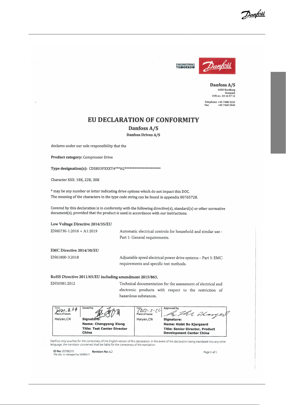
Conformity mark
EU/EC Declaration of Conformity (EC/CE - European Conformity/Conformité Européenne)
Low Voltage Directive/Electromagnetic compatibility (EMC)/Restriction of Hazardous Substances
(RoHS)
Countries of use: Europe
ACMA Declaration of Conformity (RCM - Regulatory Compliance Mark)
Australian Communications Media Authority (ACMA)
Low Voltage Directive/Electromagnetic compatibility (EMC)
Countries of use: Australia and New Zealand
VLT® Compressor Drive CDS 803
American English
Operating Guide
Introduction
1 Introduction
1.1 Purpose of this Operating Guide
This Operating Guide provides information for safe installation and commissioning of the AC drive. It is intended for use by qualified
personnel.
Read and follow the instructions to use the drive safely and professionally.
Pay particular attention to the safety instructions and general warnings. Always keep this Operating Guide with the drive.
VLT® is a registered trademark for Danfoss A/S.
1.2 Additional Resources
1.2.1 Supplementary Documentation
Other resources are available to understand advanced drive functions and programming.
•
The Programming Guide provides information on how to program and includes complete parameter descriptions.
•
The Design Guide provides detailed information about capabilities and functionality to design motor control systems.
•
The Modbus RTU Operating Instructions explains how to physically establish and configure communication between the Danfoss
FC Series and a controller using the Modbus RTU protocol. Download the Operating Instructions from www.danfoss.com in the
section Service and Support/Documentation.
See
www.danfoss.com for supplementary documentation.
1.2.2 VLT® Motion Control Tool MCT 10 Software Support
Download the software from the Service and Support download page on www.danfoss.com.
During the installation process of the software, enter CD-key 34544400 to activate the CDS 803 functionality. An activation key is not
required for using the CDS 803 functionality.
The latest software does not always contain the latest updates for the drive. Contact the local sales office for the latest drive updates
(in the form of *.upd files), or download the drive updates from the Service and Support download page on www.danfoss.com.
1.3 Manual and Software Version
This manual is regularly reviewed and updated. All suggestions for improvement are welcome.
Table 1: Manual and Software Version
1.4 Approvals and Certifications
AQ32174876762701-000301 / 130R06278 | Danfoss A/S © 2021.06
Description
Conformity mark
VIT-SEPRO Declaration of Conformity (VIT - All-Union Institute of Transformer Engineering)
Low Voltage Directive/Electromagnetic compatibility (EMC)
Country of use: Ukraine
089
Moroccan Declaration of Conformity (CMIM - Moroccan Conformity Mark)
Low Voltage Directive/Electromagnetic compatibility (EMC)
Country of use: Morocco
Eurasian Economic Union Declaration of Conformity (EAC - Eurasian Conformity Mark)
Customs Union Technical Regulations (CU TR)
Low voltage Directive/Electromagnetic compatibility (EMC)/Restriction of Hazardous Substances Direc-
tive (RoHS)
Countries of use: Eurasian Economic Union (Russia, Belarus, Kazakhstan, Armenia, and Kirghizstan)
Certification of Compliance UL listed (UL - Underwriters Laboratories)
Safety organization
Countries of use: USA and Canada
Certification of Compliance UL recognized (UL - Underwriters Laboratories)
Safety organization
Countries of use: USA and Canada
Do not dispose of equipment containing electrical components together with domestic waste.
Collect it separately in accordance with local and currently valid legislation.
VLT® Compressor Drive CDS 803
American English
Operating Guide
Introduction
N O T I C E
The VLT® Compressor Drive CDS 803 with SXXX in the type code is certified against UL 508C. Example:
CDS803P7K5T4E20H4XXCXXXSXXXXAXBXCXXXXDX
The VLT® Compressor Drive CDS 803 with S096 in the type code is certified against UL/EN/IEC 60730-1. Example:
CDS803P30KT4E20H2XXXXXXS096XAXBXCXXXXDX
1.5 Disposal
AQ32174876762701-000301 / 130R0627 | 9Danfoss A/S © 2021.06
VLT® Compressor Drive CDS 803
American English
Operating Guide
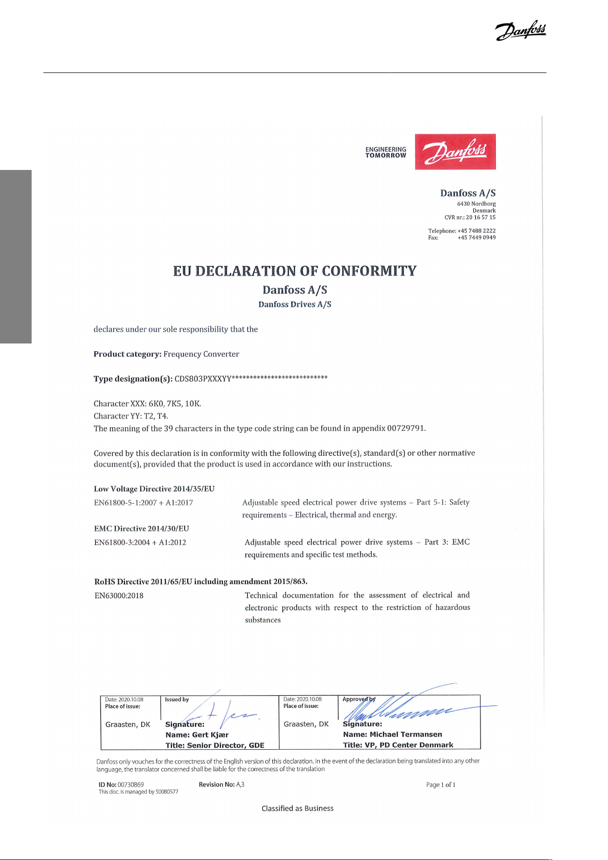
1.6 CE Declaration
Introduction
AQ32174876762701-000301 / 130R062710 | Danfoss A/S © 2021.06
VLT® Compressor Drive CDS 803
American English
Operating Guide
Introduction
AQ32174876762701-000301 / 130R0627 | 11Danfoss A/S © 2021.06
VLT® Compressor Drive CDS 803
American English
Operating Guide
2 Safety
2.1 Safety Symbols
The following symbols are used in this manual:
D A N G E R
Indicates a hazardous situation which, if not avoided, will result in death or serious injury.
W A R N I N G
Indicates a hazardous situation which, if not avoided, could result in death or serious injury.
C A U T I O N
Indicates a hazardous situation which, if not avoided, could result in minor or moderate injury.
N O T I C E
Indicates information considered important, but not hazard-related (for example, messages relating to property damage).
Safety
2.2 Qualified Personnel
To allow trouble-free and safe operation of the unit, only qualified personnel with proven skills are allowed to transport, store, assemble, install, program, commission, maintain, and decommission this equipment.
Persons with proven skills:
•
Are qualified electrical engineers, or persons who have received training from qualified electrical engineers and are suitably
experienced to operate devices, systems, plant, and machinery in accordance with pertinent laws and regulations.
•
Are familiar with the basic regulations concerning health and safety/accident prevention.
•
Have read and understood the safety guidelines given in all manuals provided with the unit, especially the instructions given in
the Operating Guide.
•
Have good knowledge of the generic and specialist standards applicable to the specific application.
2.3 Safety Precautions
W A R N I N G
HAZARDOUS VOLTAGE
AC drives contain hazardous voltage when connected to the AC mains or connected on the DC terminals. Failure to perform
installation, start-up, and maintenance by skilled personnel can result in death or serious injury.
Only skilled personnel must perform installation, start-up, and maintenance.
-
W A R N I N G
UNINTENDED START
When the drive is connected to AC mains, DC supply, or load sharing, the motor may start at any time. Unintended start during
programming, service, or repair work can result in death, serious injury, or property damage. Start the motor with an external
switch, a fieldbus command, an input reference signal from the local control panel (LCP), via remote operation using MCT 10
software, or after a cleared fault condition.
Disconnect the drive from the mains.
-
Press [Off/Reset] on the LCP before programming parameters.
-
Ensure that the drive is fully wired and assembled when it is connected to AC mains, DC supply, or load sharing.
-
AQ32174876762701-000301 / 130R062712 | Danfoss A/S © 2021.06
Voltage [V]
Power range [kW (hp)]
Minimum waiting time (minutes)
3x200
6.0–10 (8.0–15)
15
3x400
6.0–7.5 (8.0–10)
4
3x400
10–30 (15–40)
15
VLT® Compressor Drive CDS 803
American English
Operating Guide
Safety
W A R N I N G
DISCHARGE TIME
The drive contains DC-link capacitors, which can remain charged even when the drive is not powered. High voltage can be
present even when the warning indicator lights are off.
Failure to wait the specified time after power has been removed before performing service or repair work could result in death or
serious injury.
Stop the motor.
-
Disconnect AC mains, permanent magnet type motors, and remote DC-link supplies, including battery back-ups, UPS, and
-
DC-link connections to other drives.
Wait for the capacitors to discharge fully. The minimum waiting time is specified in the table Discharge time and is also visible
-
on the nameplate on the top of the drive.
Before performing any service or repair work, use an appropriate voltage measuring device to make sure that the capacitors
-
are fully discharged.
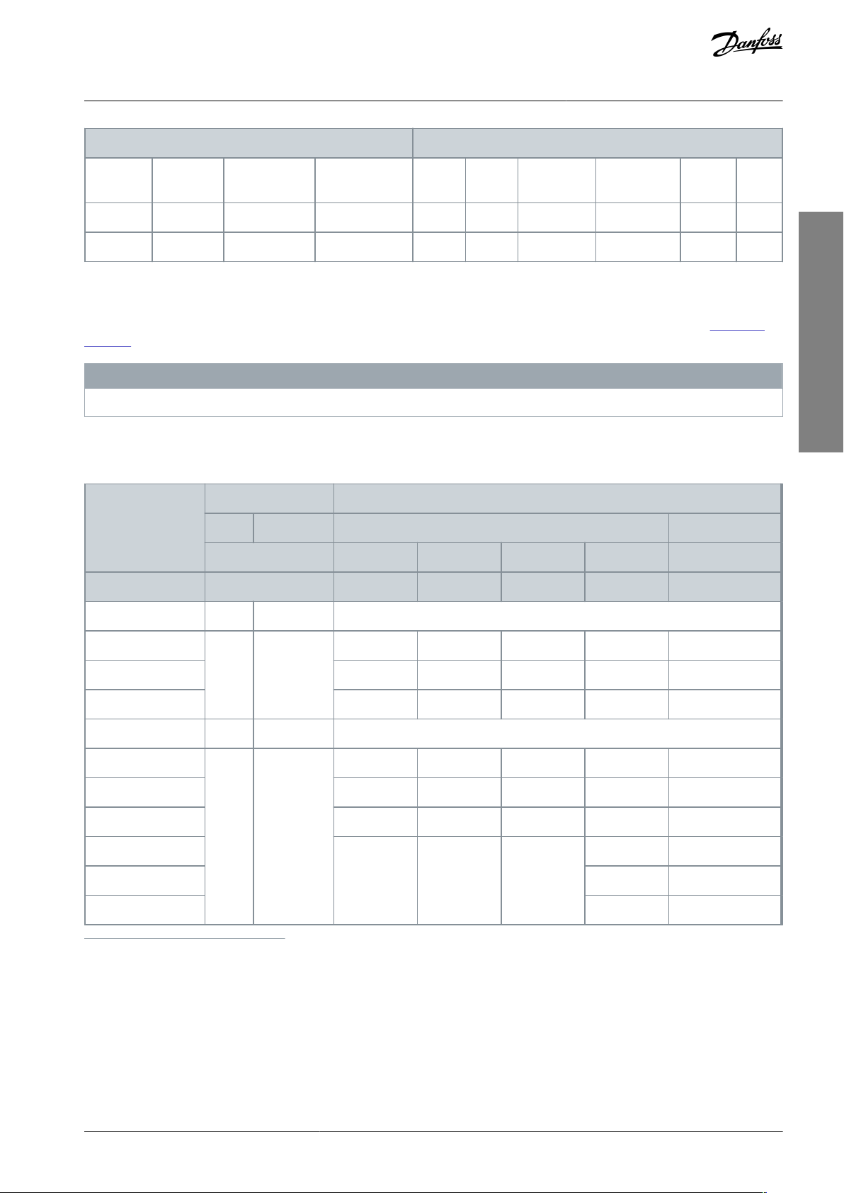
Table 2: Discharge Time
W A R N I N G
LEAKAGE CURRENT HAZARD
Leakage currents exceed 3.5 mA. Failure to ground the drive properly can result in death or serious injury.
Ensure that the minimum size of the ground conductor complies with the local safety regulations for high touch current
-
equipment.
W A R N I N G
EQUIPMENT HAZARD
Contact with rotating shafts and electrical equipment can result in death or serious injury.
Ensure that only trained and qualified personnel perform installation, start-up, and maintenance.
-
Ensure that electrical work conforms to national and local electrical codes.
-
Follow the procedures in this manual.
-
C A U T I O N
INTERNAL FAILURE HAZARD
An internal failure in the drive can result in serious injury when the drive is not properly closed.
Ensure that all safety covers are in place and securely fastened before applying power.
-
AQ32174876762701-000301 / 130R0627 | 13Danfoss A/S © 2021.06
Power [kW (hp)]
Clearance above/below [mm (in)]
Size
IP protection rating
3x200–240 V
3x380–480 V
H3
IP20–6.0–7.5 (8.0–10)
100 (4)
H4
IP20
6.0–7.5 (8.0–10)
10 (15)
100 (4)
H5
IP20
10 (15)
18.5–22 (25–30)
100 (4)
H6
IP20–30(40)
200 (7.9)
Power [kW (hp)]
Torque [Nm (in-lb)]
Enclosure size
IP protection rating
3x200–240 V
3x380–480 V
Mains
Motor
DC connection
Control terminals
Ground
Relay
H3
IP20–6.0–7.5 (8.0–10)
0.8 (7)
0.8 (7)
0.8 (7)
0.5 (4)
0.8 (7)
0.5 (4)
VLT® Compressor Drive CDS 803
American English
Operating Guide
3 Installation
3.1 Mechanical Installation
3.1.1 Side-by-side Installation
The drive can be mounted side by side but requires the clearance specified in Table 3 above and below for cooling.
Table 3: Clearance Required for Cooling
N O T I C E
With IP21/NEMA Type1 option kit mounted, a distance of 50 mm (2 in) between the units is required.
Installation
3.1.2 Operating Environment
3.1.2.1 Derating for Ambient Temperature and Switching Frequency
Ensure that the ambient temperature measured over 24 hours is at least 5 °C (9 °F) lower than the maximum ambient temperature
that is specified for the drive. If the drive is operated at a high ambient temperature, decrease the constant output current. For
derating specifications, see the VLT® Compressor Drive CDS 803 Design Guide listed in
1.1.2 Additional Resources.
3.1.2.2 Derating for Low Air Pressure and High Altitudes
The cooling capability of air is decreased at low air pressure. For altitudes above 2000 m (6562 ft), contact Danfoss regarding PELV.
Below 1000 m (3281 ft) altitude, derating is not necessary. For altitudes above 1000 m (3281 ft), decrease the ambient temperature
or the maximum output current. Decrease the output by 1% per 100 m (328 ft) altitude above 1000 m (3281 ft) or reduce the maximum ambient cooling air temperature by 1 °C (1.8 °F) per 200 m (656 ft).
3.2 Electrical Installation
3.2.1 Electrical Installation in General
All cabling must comply with national and local regulations on cable cross-sections and ambient temperature. Copper conductors
are required. 75 °C (167 °F) is recommended.
3.2.1.1 Fastener Torque Ratings
Table 4: Tightening Torques for Enclosure Sizes H3–H6, 3x200–240 V & 3x380–480 V
AQ32174876762701-000301 / 130R062714 | Danfoss A/S © 2021.06
Power [kW (hp)]
Torque [Nm (in-lb)]
H4
IP20
6.0–7.5 (8.0–
10)
10–15 (15–20)
1.2 (11)
1.2 (11)
1.2 (11)
0.5 (4)
0.8 (7)
0.5 (4)
H5
IP20
10 (15)
18.5–22 (25–30)
1.2 (11)
1.2 (11)
1.2 (11)
0.5 (4)
0.8 (7)
0.5 (4)
H6
IP20–30 (40)
4.5 (40)
4.5 (40)
–
0.5 (4)
3 (27)
0.5 (4)
Circuit breakers
(1)
Fuse
UL
Non-ULULNon-UL
Bussmann
Bussmann
Bussmann
Bussmann
Maximum fuse
Power [kW (hp)]
Type RK5
Type RK1
Type J
Type T
Type gG
3x200–240 V
6.0 (8.0)
–
–
FRS-R-50
KTN-R50
JKS-50
JJN-50
gG-50
7.5 (10)
FRS-R-50
KTN-R50
JKS-50
JJN-50
gG-50
10 (15)
FRS-R-80
KTN-R80
JKS-80
JJN-80
gG-63
3x380–480 V
6.0 (8.0)
–
–
FRS-R-25
KTS-R25
JKS-25
JJS-25
gG-25
7.5 (10)
FRS-R-25
KTS-R25
JKS-25
JJS-25
gG-25
10 (15)
FRS-R-50
KTS-R50
JKS-50
JJS-50
gG-50
18.5 (25)
–––
JJS-80
gG-63
22 (30)
JJS-80
gG-63
30 (40)
JJS-125
gG-80
VLT® Compressor Drive CDS 803
American English
Operating Guide
Installation
3.2.2 Fuses and Circuit Breakers
Fuses and circuit breakers ensure that possible damage to the drive is limited to damage inside the unit. Danfoss recommends fuses
on the supply side as protection. For further information, see the application note Fuses and Circuit Breakers found on www.dan-
foss.com under Service and support/Documentation/Manuals & guides.
N O T I C E
Use of fuses on the supply side is mandatory for IEC 60364 (CE) and NEC 2009 (UL) compliant installations.
3.2.2.1 Recommendation of Fuses and Circuit Breakers
Table 5: Fuses and Circuit Breakers
1
Circuit breakers have not been evaluated by Danfoss as part of the certification process.
3.2.3 Electrical Wiring
3.2.3.1 Wiring Schematic
AQ32174876762701-000301 / 130R0627 | 15Danfoss A/S © 2021.06
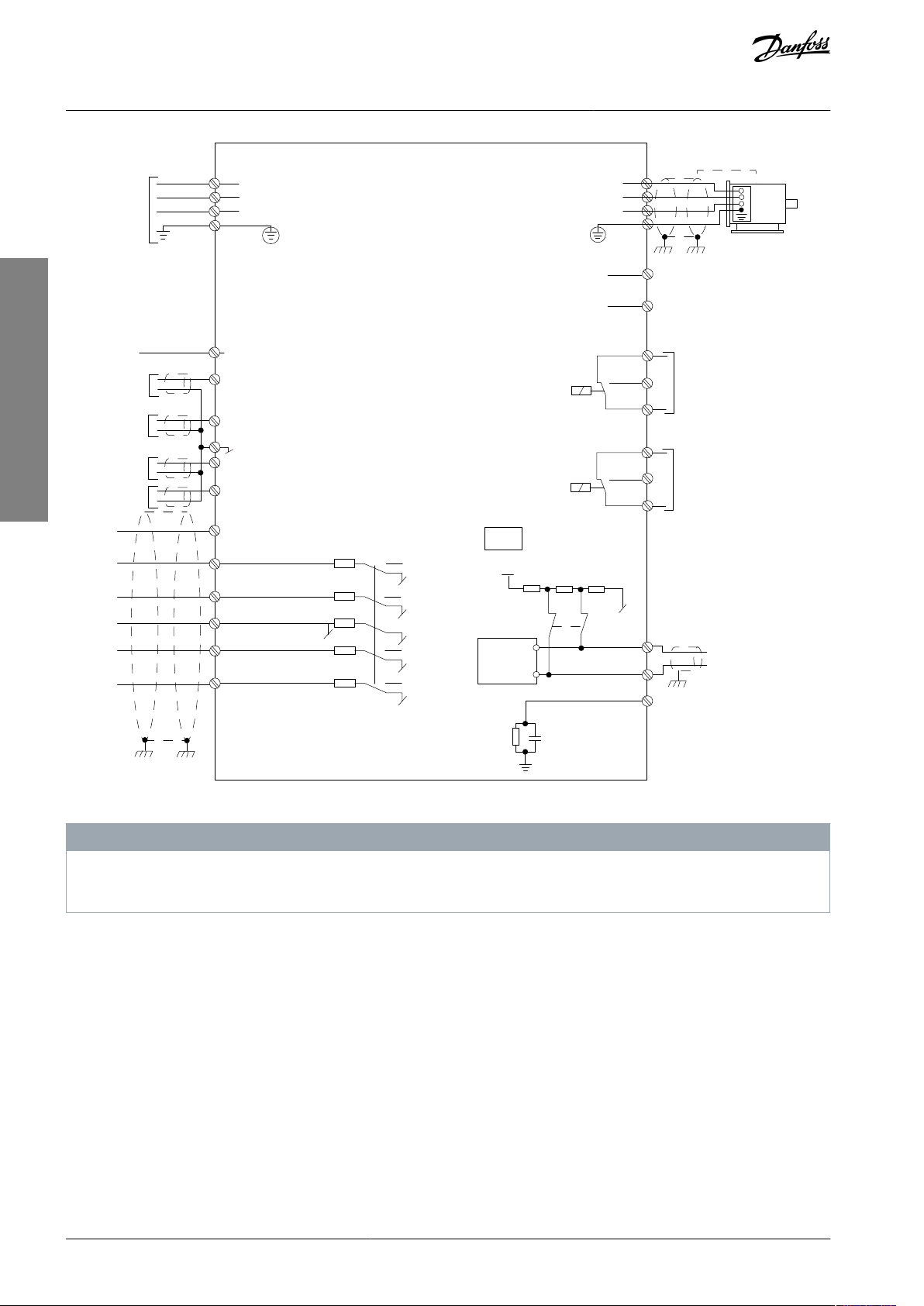
L1
L2
L3
3-phase
power
input
PE
PE
+10 V DC
0-10 V DC-
0-10 V DC-
50 (+10 V OUT)
54 (A IN)
53 (A IN)
55 (COM A IN/OUT)
0/4-20 mA
0/4-20 mA
42 0/4-20 mA A OUT / D OUT
45 0/4-20 mA A OUT / D OUT
18 (D IN)
19 (D IN)
27 (D IN)
29 (
D IN)
12 (+24 V OUT)
24 V (NPN)
20 (COM D IN)
O V (PNP)
24 V (NPN)
O V (PNP)
24 V (NPN)
O V (PNP)
24 V (NPN)
O V (PNP)
Bus ter.
Bus ter.
RS485
Interface
RS485
(N RS485) 69
(P RS485) 68
(Com RS485 ) 61
(PNP)-Source
(NPN)-Sink
ON=Terminated
OFF=Unterminated
ON
1 2
240 V AC 3 A
Not present on all power sizes
Do not connect shield to 61
01
02
03
relay 1
relay 2
UDC+
UDC-
Motor
U
V
W
e30bj246.10
06
05
04
240 V AC 3 A
VLT® Compressor Drive CDS 803
American English
Operating Guide
Installation
Illustration 1: Basic Wiring Schematic Drawing
There is no access to UDC- and UDC+ on the following units:
IP20, 380–480 V, 30 kW (40 hp).
-
N O T I C E
AQ32174876762701-000301 / 130R062716 | Danfoss A/S © 2021.06
1
2
2
3
4
U
V
W
-DC
+DC
e30bb634.11
5
MAINS
MOTOR
1
Mains
2
Ground
3
Compressor
4
Relays
5
Control terminals
VLT® Compressor Drive CDS 803
American English
Operating Guide
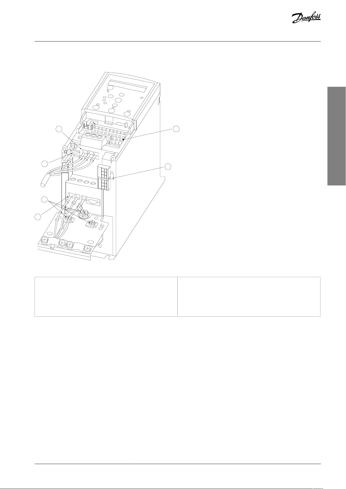
3.2.3.2 Terminal Overview of Enclosure Sizes H3–H5
Installation
Illustration 2: Enclosure Sizes H3–H5
AQ32174876762701-000301 / 130R0627 | 17Danfoss A/S © 2021.06
1
95
99
L1 91 / L2 92 / L3 93
U 96 /
V 97 /
W 98
03 02 01
06 05 04
2
3
4
e30bb762.12
1
Mains
2
Ground
3
Compressor
4
Relays
e30bi968.10
VLT® Compressor Drive CDS 803
American English
Operating Guide
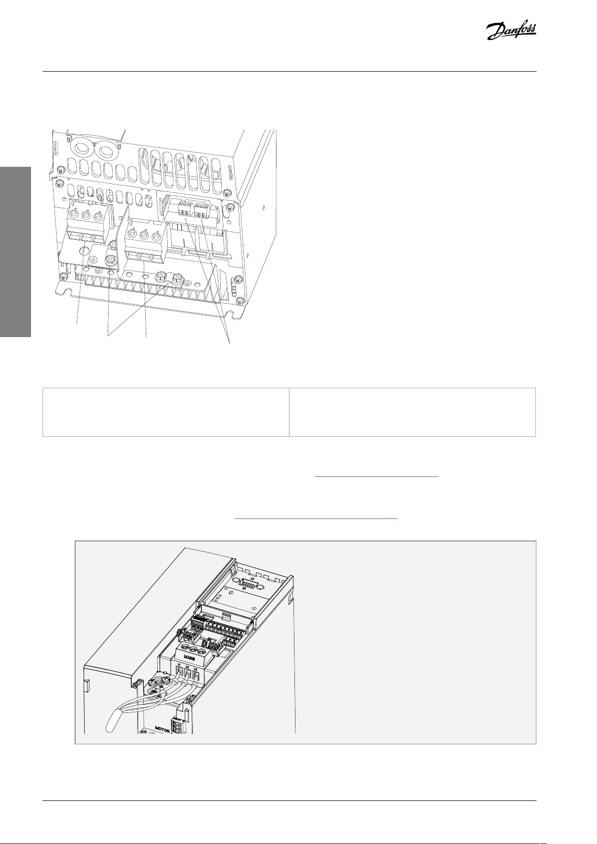
3.2.3.3 Terminal Overview of Enclosure Size H6
Installation
Illustration 3: Enclosure Size H6
3.2.3.4 Connecting to Mains and Compressor Terminals
•
Tighten all terminals in accordance with the information provided in 1.3.2.1.1 Fastener Torque Ratings.
•
Keep the compressor cable as short as possible to reduce the noise level and leakage currents.
•
Use a shielded/armored compressor cable to comply with the EMC emission specifications and connect this cable to both the
decoupling plate and the compressor. Also see 1.3.2.5 EMC-compliant Electrical Installation.
1.
Connect the ground cable to the ground terminal, then connect the mains supply to terminals L1, L2, and L3.
AQ32174876762701-000301 / 130R062718 | Danfoss A/S © 2021.06
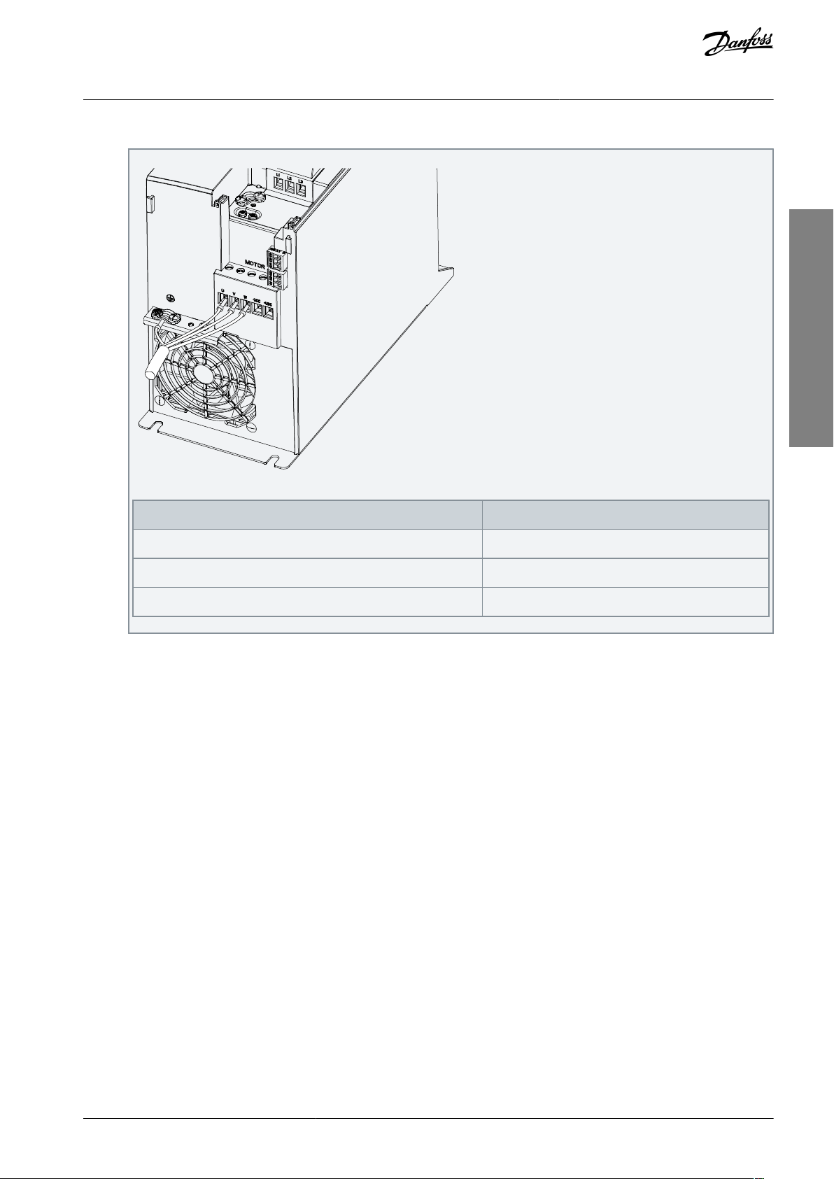
e30bi967.10
Drive terminals
Compressor
UT1VT2W
T3
VLT® Compressor Drive CDS 803
American English
Operating Guide
2.
Connect the ground cable to the ground terminal, then connect the compressor to terminals U, V, and W.
Table 6: Connection of Compressor to Terminals
Installation
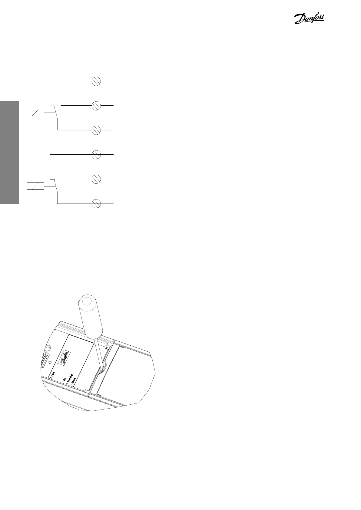
3.2.3.5 Relay Terminals
Relay 1
•
Terminal 01: Common.
•
Terminal 02: Normally open.
•
Terminal 03: Normally closed.
Relay 2
•
Terminal 04: Common.
•
Terminal 05: Normally open.
•
Terminal 06: Normally closed.
AQ32174876762701-000301 / 130R0627 | 19Danfoss A/S © 2021.06
Relay1
Relay2
03
02
01
06
05
04
e30bi798.10
e30bd331.11
VLT® Compressor Drive CDS 803
American English
Operating Guide
Installation
Illustration 4: Relay Outputs 1 and 2
3.2.3.6 Control Terminals
Remove the terminal cover to access the control terminals.
Use a flat-edged screwdriver to push down the lock lever of the terminal cover under the LCP, then remove the terminal cover as
shown in the following illustration.
Illustration 5: Removing the Terminal Cover
The following illustration shows all the drive control terminals. Applying start (terminal 18), connection between terminals 12-27,
and an analog reference (terminal 53 or 54, and 55) make the drive run.
The digital input mode of terminal 18, 19, 27, and 29 is set in parameter 5-00 Digital Input Mode (PNP is default value).
AQ32174876762701-000301 / 130R062720 | Danfoss A/S © 2021.06
e30bf892.10
12 20 55
181927 29 42 54
45 50 53
DIGI IN
61 68 69
N
P
COMM. GND
+24 V
GND
GND
10 V OUT
10 V/20 mA IN
0/4-20 mA A OUT/DIG OUT
BUS TER.
OFF ON
DIGI IN
DIGI IN
DIGI IN
0/4-20 mA A OUT/DIG OUT
10 V/20 mA IN
VLT® Compressor Drive CDS 803
American English
Operating Guide
Illustration 6: Control Terminals
Installation
3.2.4 Setting Up RS485 Serial Communication
3.2.4.1 RS485 Features
RS485 is a 2-wire bus interface compatible with multi-drop network topology. This interface contains the following features:
•
Ability to select from the following communication protocols:
-
FC (default protocol)
-
Modbus RTU
•
Functions can be programmed remotely using the RS485 connection or in parameter group 8-** Communications and Options.
•
A switch (BUS TER) is provided on the control card for bus termination resistance.
N O T I C E
Altering between the supported communication protocols can be accessed and changed via the LCP as parameter 8-30 Protocol is
not available in VLT® Motion Control Tool MCT 10.
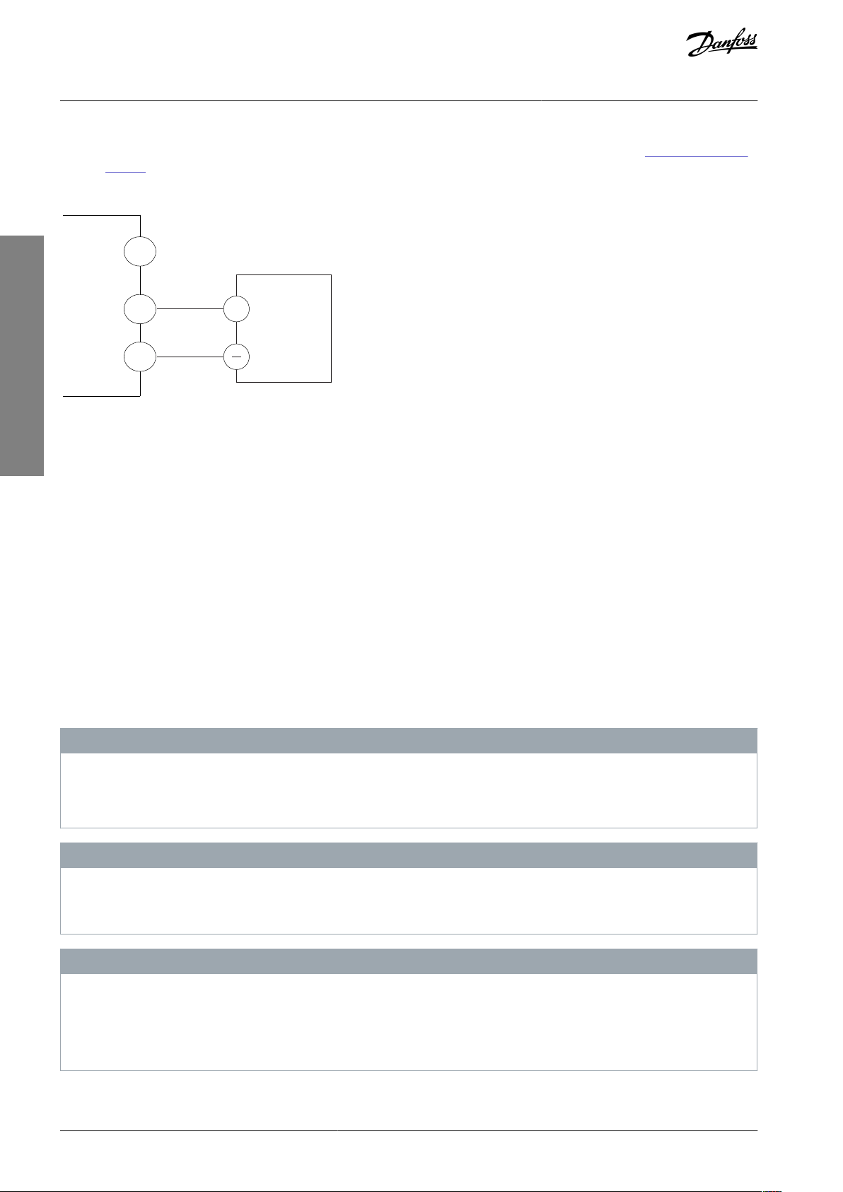
3.2.4.2 Configuring RS485 Serial Communication
Procedure
1.
Connect RS485 serial communication wiring to terminals (P RS485) 68 and (N RS485) 69.
-
Use shielded serial communication cable.
-
Properly ground the wiring. Refer to 1.3.2.5 EMC-compliant Electrical Installation.
AQ32174876762701-000301 / 130R0627 | 21Danfoss A/S © 2021.06
+
e30bi768.10
RS485
69
GND
68
VLT® Compressor Drive CDS 803
American English
Operating Guide
2.
Configure all required settings such as address, baud rate, and so on in parameter group 8-** Communications and Options.
For more details on parameters, refer to VLT® Compressor Drive CDS 803 Programming Guide listed in 1.1.2 Additional Re-
sources.
Example
Illustration 7: RS485 Wiring Connection
Installation
3.2.5 EMC-compliant Electrical Installation
To obtain an EMC-compliant installation, be sure to follow all electrical installation instructions. Also, remember to practice the following:
•
When using relays, control cables, a signal interface, fieldbus, or brake, connect the shield to the enclosure at both ends. If the
ground path has high impedance, is noisy, or is carrying current, break the shield connection on 1 end to avoid ground current
loops.
•
Convey the currents back to the unit using a metal mounting plate. Ensure good electrical contact from the mounting plate by
securely fastening the mounting screws to the drive chassis.
•
Use shielded cables for motor output cables. An alternative is unshielded motor cables within metal conduit.
•
Ensure that motor and brake cables are as short as possible to reduce the interference level from the entire system.
•
Avoid placing cables with a sensitive signal level alongside motor and brake cables.
•
For communication and command/control lines, follow the particular communication protocol standards. For example, USB
must use shielded cables, but RS485/ethernet can use shielded UTP or unshielded UTP cables.
•
Ensure that all control terminal connections are rated protective extra low voltage (PELV).
N O T I C E
TWISTED SHIELD ENDS (PIGTAILS)
Twisted shield ends increase shield impedance at higher frequencies, which increases the leakage current.
Use integrated shield clamps instead of twisted shield ends.
-
N O T I C E
SHIELDED CABLES
If shielded cables or metal conduits are not used, the unit and the installation do not meet regulatory limits on radio frequency
(RF) emission levels.
N O T I C E
EMC INTERFERENCE
Failure to isolate power, motor, and control cables can result in unintended behavior or reduced performance.
Use shielded cables for motor and control wiring.
-
Provide a minimum 200 mm (7.9 in) separation between mains input, motor cables, and control cables.
-
AQ32174876762701-000301 / 130R062722 | Danfoss A/S © 2021.06

VLT® Compressor Drive CDS 803
American English
Operating Guide
Installation
N O T I C E
EMI/EMC NON-COMPLIANCE
Panel components not installed by Danfoss will invalidate the EMI/EMC compliance and other certifications.
N O T I C E
INSTALLATION AT HIGH ALTITUDE
There is a risk for overvoltage. Isolation between components and critical parts could be insufficient and may not comply with
PELV requirements.
Use external protective devices or galvanic isolation. For installations above 2000 m (6500 ft) altitude, contact Danfoss re-
-
garding protective extra low voltage (PELV) compliance.
N O T I C E
PROTECTIVE EXTRA LOW VOLTAGE (PELV) COMPLIANCE
Prevent electric shock by using PELV electrical supply and complying with local and national PELV regulations.
AQ32174876762701-000301 / 130R0627 | 23Danfoss A/S © 2021.06
L1
L2L3PEL1L2L3PEPEu
v
w
2
1
3
5
IEC 60309
16
17
18
14
12
8
7
10
9
4
11
13
446
15
90
+DC
BR-
B
M
AINS
L1 L2 L3
91 92 93
RELA
Y 1 RELA
Y 2
99
- L
C -
UV
W
MO
T
OR
VLT® Compressor Drive CDS 803
American English
Operating Guide
Installation
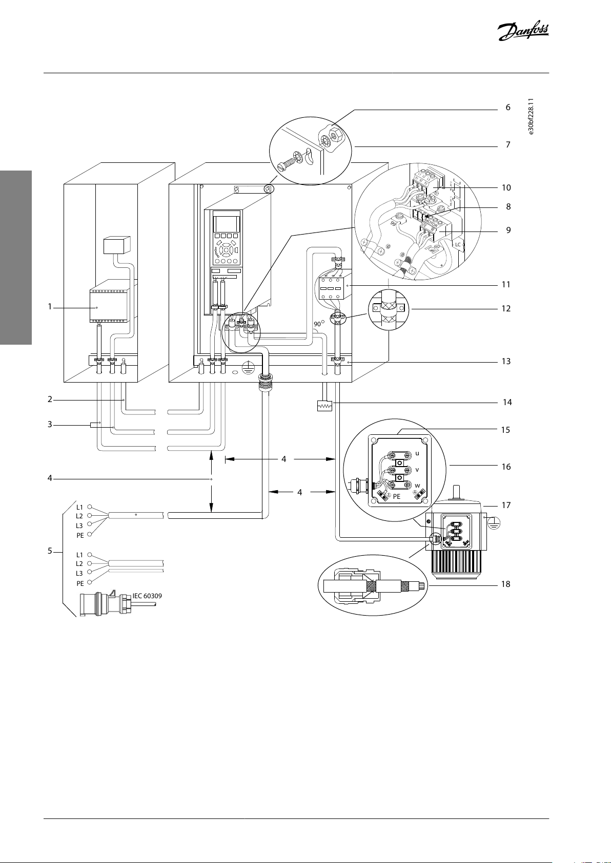
Illustration 8: Example of Proper EMC Installation
AQ32174876762701-000301 / 130R062724 | Danfoss A/S © 2021.06

1
Programmable logic controller (PLC)
2
Minimum 16 mm2 (6 AWG) equalizing cable
3
Control cables
4
Minimum 200 mm (7.9 in) between control cables,
motor cables, and mains cables
5
Mains supply
6
Bare (unpainted) surface
7
Star washers
8
Brake cable (shielded)
9
Motor cable (shielded)
10
Mains cable (unshielded)
11
Output contactor
12
Cable insulation stripped
13
Common ground busbar. Follow local and national
requirements for cabinet grounding.
14
Brake resistor
15
Metal box
16
Connection to motor
17
Motor
18
EMC cable gland
VLT® Compressor Drive CDS 803
American English
Operating Guide
Installation
AQ32174876762701-000301 / 130R0627 | 25Danfoss A/S © 2021.06
e30bb765.11
B
a
c
k
Com.
1-20 Motor Power
[5] 0.37kW - 0.5HP
Setup 1
A
B
1
12
13
14
15
11
11
10
9
8
7
6
5
4
3
2
C
D
Status
Main
Menu
Quick
Menu
Hand
On
OK
M
enu
Off
Reset
Auto
On
Alarm
Warn.
On
11
1
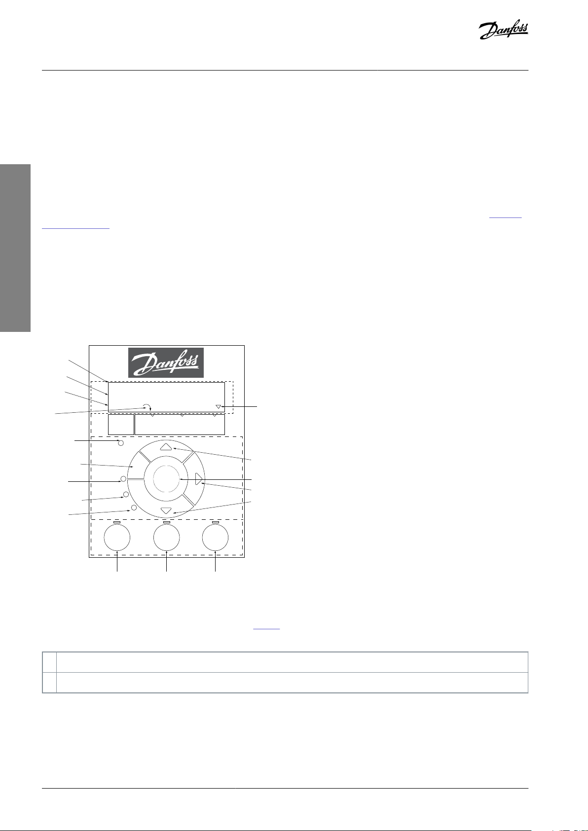
Parameter number and name.
2
Parameter value.
VLT® Compressor Drive CDS 803
American English
Operating Guide
Commissioning
4 Commissioning
4.1 Programming Interfaces
The drive can be programmed in 3 different ways:
•
Locally via the LCP.
•
Externally via the RS485 interface by either
-
using Modbus RTU
-
or by installing VLT® Motion Control Tool MCT 10.
For the full menu and parameter specifications, refer to the VLT® Compressor Drive CDS 803 Programming Guide listed in 1.1.2 Ad-
ditional Resources.
4.2 Local Control Panel (LCP)
The LCP is divided into 4 functional sections.
•
A. Display
•
B. Menu key
•
C. Navigation keys and indicator lights
•
D. Operation keys and indicator lights
Illustration 9: Local Control Panel (LCP)
A. Display
The LCD display is illuminated with 2 alphanumeric lines. Table 7 describes the information that can be read from the display.
Table 7: Legend to Section A
AQ32174876762701-000301 / 130R062726 | Danfoss A/S © 2021.06
3
Setup number shows the active setup and the edit setup. If the same setup acts as both active and edit setup, only that setup
number is shown (factory setting). When active and edit setup differ, both numbers are shown in the display (setup 12). The
number flashing indicates the edit setup.
4
Motor direction is shown to the bottom left of the display – indicated by a small arrow pointing either clockwise or counterclockwise.
5
The triangle indicates if the LCP is in Status, Quick Menu, or Main Menu.
6
Com. (yellow indicator): Flashes during bus communication.
7
On (green indicator): Control section is working correctly.
8
Warn. (yellow indicator): Indicates a warning.
9
Alarm (red indicator): Indicates an alarm.
10
[Back]: For moving to the previous step or layer in the navigation structure.
11
[▵] [▿] [▹]: For navigating among parameter groups and parameters, and within parameters. They can also be used for setting local reference.
12
[OK]: For selecting a parameter and for accepting changes to parameter settings.
13
[Hand On]: Starts the motor and enables control of the drive via the LCP.
N O T I C E
[2] Coast inverse is the default option for parameter 5-12 Terminal 27 Digital Input. If there is no 24 V supply to terminal 27,
[Hand On] does not start the compressor. Connect terminal 12 to terminal 27.
14
[Off/Reset]: Stops the compressor (Off). If in alarm mode, the alarm is reset.
15
[Auto On]: The drive is controlled either via control terminals or serial communication.
VLT® Compressor Drive CDS 803
American English
Operating Guide
B. Menu key
Press [Menu] to select among Status, Quick Menu, or Main Menu.
C. Navigation keys and indicator lights
Table 8: Legend to Section C
Commissioning
D. Operation keys and indicator lights
Table 9: Legend to Section D
4.2.1 Programming via the Quick Menu
Procedure
1.
To enter the Quick Menu, press [Menu] until indicator in display is placed above Quick Menu.
2.
Press [▵] [▿] to select quick guide, closed-loop setup, compressor setup, or changes made, then press [OK].
3.
Press [▵] [▿] to browse through the parameters in the Quick Menu.
Press [OK] to select a parameter.
4.
Press [▵] [▿] to change the value of a parameter setting.
5.
Press [OK] to accept the change.
6.
7.
Press either [Back] twice to enter Status, or press [Menu] once to enter Main Menu.
4.2.2 Programming via the Main Menu
Procedure
1.
Press [Menu] until indicator in display is placed above Main Menu.
Press [▵] [▿] to browse through the parameter groups.
2.
AQ32174876762701-000301 / 130R0627 | 27Danfoss A/S © 2021.06
VLT® Compressor Drive CDS 803
American English
Operating Guide
3.
Press [OK] to select a parameter group.
4.
Press [▵] [▿] to browse through the parameters in the specific group.
5.
Press [OK] to select the parameter.
6.
Press [▵] [▿] to set/change the parameter value.
7.
Press [OK] to accept the change or press [Back] to go back to the previous level.
Commissioning
4.2.3 Data Transfer from Drive to LCP
Once the setup of a drive is complete, Danfoss recommends storing the data in the LCP or on a PC via VLT® Motion Control Tool
MCT 10.
W A R N I N G
Stop the compressor before performing this operation.
Procedure
1.
Go to parameter 0-50 LCP Copy.
2.
Press [OK].
3.
Select [1] All to LCP.
Press [OK].
4.
4.2.4 Data Transfer from LCP to Drive
Connect the LCP to another drive to copy the parameter settings to this drive as well.
W A R N I N G
Stop the compressor before performing this operation.
Procedure
1.
Go to parameter 0-50 LCP Copy.
2.
Press [OK].
3.
Select [2] All from LCP.
4.
Press [OK].
4.2.5 Restoring Factory Default Settings
There are 2 different ways of initializing the drive to factory default settings:
•
Via parameter 14-22 Operation Mode (this is the recommended way).
Two-finger initialization
•
Some parameters will not be reset, see more details in
and 1.4.2.5.2 Two-finger Initialization.
4.2.5.1 Recommended Initialization (via Parameter 14-22 Operation Mode)
Initialization of the drive to default settings (via parameter 14-22 Operation Mode).
Procedure
1.
Select parameter 14-22 Operation Mode.
2.
Press [OK].
3.
Select [2] Initialisation and press [OK].
Cut off the mains supply and wait until the display turns off.
4.
Reconnect the mains supply.
5.
1.4.2.5.1 Recommended Initialization (via Parameter 14-22 Operation Mode)
The drive is now reset, except the following parameters:
Parameter 1-06 Clockwise Direction
Parameter 1-13 Compressor Selection
Parameter 4-18 Current Limit
Parameter 8-30 Protocol
AQ32174876762701-000301 / 130R062728 | Danfoss A/S © 2021.06

VLT® Compressor Drive CDS 803
American English
Operating Guide
Parameter 8-31 Address
Parameter 8-32 Baud Rate
Parameter 8-33 Parity / Stop Bits
Parameter 8-35 Minimum Response Delay
Parameter 8-36 Maximum Response Delay
Parameter 8-37 Maximum Inter-char delay
Parameter 15-00 Operating hours to parameter 15-05 Over Volt's
Parameter 15-03 Power Up's
Parameter 15-04 Over Temp's
Parameter 15-05 Over Volt's
Parameter 15-30 Alarm Log: Error Code
Parameter group 15-4* Drive identification parameters
4.2.5.2 Two-finger Initialization
Procedure
1.
Power off the drive.
2.
Press [OK] and [Menu].
3.
Power up the drive while still pressing the keys above for 10 s.
Commissioning
The drive is now reset, except the following parameters:
Parameter 1-06 Clockwise Direction
Parameter 15-00 Operating hours
Parameter 15-03 Power Up's
Parameter 15-04 Over Temp's
Parameter 15-05 Over Volt's
Parameter 15-30 Alarm Log: Error Code
Parameter group 15-4* Drive identification parameters
Initialization of parameters is confirmed by AL80 in the display after the power cycle.
4.3 Starting Up the Drive for the First Time
The procedure in this section requires user-wiring and application programming to be completed. The following procedure is recommended after application setup is completed.
1.
Press [Auto On].
If warnings or alarms occur, see the Warnings and Alarms section.
Apply an external run command. Examples of external run commands are a switch, button, or programmable logic control-
2.
ler (PLC).
Adjust the speed reference throughout the speed range.
3.
Ensure that the system is working as intended by checking the sound and vibration levels of the compressor.
4.
Remove the external run command.
5.
AQ32174876762701-000301 / 130R0627 | 29Danfoss A/S © 2021.06
Status
Color
Warning
Constant yellow light
Alarm
Flashing red light
VLT® Compressor Drive CDS 803
American English
Operating Guide
Troubleshooting
5 Troubleshooting
5.1 Acoustic Noise or Vibration
If the compressor application makes noise or vibrations at certain frequencies, adjust the following parameters to avoid resonance
problems within the system.
•
Upper and lower frequency limits, Parameter group 4-6* Speed Bypass.
•
Switching pattern and switching frequency, parameter group 14-0* Inverter Switching.
5.2 Warnings and Alarms
A warning or an alarm is signaled by the relevant indicator on the front of the drive and indicated by a code on the display.
A warning remains active until its cause is no longer present. Under certain circumstances, operation of the compressor may still be
continued. Warning messages may be critical.
In the event of an alarm, the drive has tripped. To restart operation, reset alarms once their cause has been rectified.
This may be done in 4 ways:
By pressing [Reset].
•
Via a digital input with the Reset function.
•
Via serial communication.
•
•
By resetting automatically using the [Auto Reset] function, see parameter 14-20 Reset Mode.
A trip is the action following an alarm. The trip coasts the compressor and is reset by pressing [Reset] or by a digital input (parameter
group 5-1* Digital Inputs). The original event that caused an alarm cannot damage the drive or cause dangerous conditions. A trip
lock is an action when an alarm occurs, which could damage the drive or connected parts. A trip lock situation can only be reset by
cycling power.
Refer to the VLT® Compressor Drive CDS 803 Programming Guide listed in
gramming.
1.1.2 Additional Resources for parameter details and pro-
Table 10: Indicator Lights
The alarm words, warning words and extended status words can be read out via serial bus or optional fieldbus for diagnosis. See
also parameter 16-90 Alarm Word, parameter 16-92 Warning Word, and parameter 16-94 Ext. Status Word.
N O T I C E
MOTOR RESTART
After a manual reset pressing [Reset], press [Auto On] or [Hand On] to restart the motor.
If an alarm cannot be reset, the reason may be that its cause has not been rectified, or the alarm is trip-locked, see Table 11.
C A U T I O N
ALARM RESET
Alarms that are trip-locked offer extra protection, meaning that the mains supply must be switched off before the alarm can be
reset. After being switched back on, the drive is no longer blocked and may be reset as described above once the cause has been
rectified.
Alarms that are not trip-locked can also be reset using the automatic reset function in parameter 14-20 Reset Mode (Warning: automatic wake-up is possible!)
alarm for a given fault.
Table 11 specifies whether a warning occurs before an alarm, or whether to show a warning or an
AQ32174876762701-000301 / 130R062730 | Danfoss A/S © 2021.06

Fault
number
Fault text
Warning
Alarm
Trip
locked
Cause of problem
2
Live zero error
X
X
Signal on terminal 53 or 54 is less than 50% of the value set in
parameter 6-10 Terminal 53 Low Voltage, parameter 6-12 Terminal 53 Low Current, parameter 6-20 Terminal 54 Low Voltage, or
parameter 6-22 Terminal 54 Low Current. See also parameter
group 6-0* Analog I/O Mode.
3
No motor
X
(1)
No motor is connected.
4
Mains ph. loss
XXX
Missing phase on the supply side or too high voltage imbalance. Check the supply voltage. See parameter 14-12 Response
to Mains Imbalance.
7
DC over volt
XXDC-link voltage exceeds limit.
8
DC under volt
X
X
DC-link voltage drops below voltage warning low limit.
9
Inverter overld.
XXMore than 100% load for too long.
10
Motor ETR over
X
(2)
X
The compressor is too hot due to more than 100% load for too
long.11Motor th over
XXThe thermistor or the thermistor connection is disconnected.
13
Overcurrent
XXX
Inverter peak current limit is exceeded.
14
Earth Fault
XXX
Discharge from output phases to ground.
16
Short Circuit
XXShort circuit in the motor or on the motor terminals.
17
Ctrl. word TO
X
X
No communication to the drive. See parameter group 8-0*
General Settings.
18
Start failed
X
The speed has not been able to exceed parameter 1-78 Motor
Start Min Speed [Hz] during start within the allowed time.
30
U phase loss
X
X
(2)
Motor phase U is missing. Check the phase.
For 6–10 kW drives: See parameter 4-58 Missing Motor Phase
Function.
31
V phase loss
X
X
(2)
Motor phase V is missing. Check the phase.
For 6–10 kW drives: See parameter 4-58 Missing Motor Phase
Function.
32
W phase loss
X
X
(2)
Motor phase W is missing. Check the phase.
For 6–10 kW drives: See parameter 4-58 Missing Motor Phase
Function.
36
Mains failure
XXSupply voltage to the drive is lost.
38
Internal fault
XXContact the local Danfoss supplier.
VLT® Compressor Drive CDS 803
American English
Operating Guide
Table 11: Warnings and Alarms
Troubleshooting
AQ32174876762701-000301 / 130R0627 | 31Danfoss A/S © 2021.06

Fault
number
Fault text
Warning
Alarm
Trip
locked
Cause of problem
46
Gate drive voltage
fault
XXThe supply on the power card is out of range.
47
24V supply low
XXX
24 V DC may be overloaded.
49
Speed limit
X
The compressor runs at a speed lower than specified in pa-
rameter 1-87 Compressor Min Speed for Trip [Hz].
50
AMA calibration
X
AMA calibration failed
51
AMA check
U
nom,Inom
X
Motor voltage, current and power configured wrong in parameters.
52
AMA low,I
nom
X
Motor current too low.
53
AMA big motor
X
Motor is too large for the AMA to be performed.
54
AMA small mot
X
Motor is too small for the AMA to be performed.
55
AMA par. range
X
Parameter values found is outside of the acceptable range.
56
AMA interrupt
X
The AMA is interrupted by user.
57
AMA timeout
X
The AMA takes too long time to complete.
58
AMA internal
X
Contact the local Danfoss supplier.
59
Current limit
X
X
The current is higher than the value in parameter 4-18 Current
Limit.
60
External interlock
X
External interlock has been activated. To resume normal operation, apply 24 V DC to the terminal programmed for external
interlock and reset the drive (via serial communication, digital
I/O, or by pressing [Off/Reset]).
66
Heat Sink Temperature Low
X
(3)
This warning is based on the temperature sensor in the IGBT
module.
69
Pwr. Card Temp
XXX
The internal temperature has exceeded the allowed operating
boundary. Check that the ambient operating temperature is
within the limits. Check the fan operation.
80
Drive initialised
X
All parameter settings are initialized to default settings.
87
Auto DC Braking
X
The drive is auto DC braking.
95
Broken belt
X
(2)X(2)
The torque is below the torque level set for no load indicating
a broken belt.
96
Start delayed
X
Power to the drive has been on for a shorter time than specified in parameter 28-01 Interval Between Starts twice.
97
Stop delayed
X
Stopping the motor has been delayed due to short cycle protection being active.
VLT® Compressor Drive CDS 803
American English
Operating Guide
Troubleshooting
AQ32174876762701-000301 / 130R062732 | Danfoss A/S © 2021.06

Fault
number
Fault text
Warning
Alarm
Trip
locked
Cause of problem
99
Locked rotor
X
The rotor is blocked or cannot run due to heavy load.
126
Motor Rotating
X
High back EMF voltage. Stop the rotor of the PM motor.
127
Back EMF too high
X
The drive cannot start the motor due to the rotor running at a
higher speed than normal condition.
208
ORM Fault
XXRunning in hand mode with low speed for too long time.
VLT® Compressor Drive CDS 803
American English
Operating Guide
1
Only applicable for 18–30 kW.
2
Only applicable for 6–10 kW.
3
Only applicable for 30 kW.
Troubleshooting
For full specifications of warnings and alarms, refer to the VLT® Compressor Drives CDS 803 Programming Guide listed in
tional Resources.
1.1.2 Addi-
AQ32174876762701-000301 / 130R0627 | 33Danfoss A/S © 2021.06

P6K0
P7K5
P10K
Typical shaft output [kW]
6.0
7.510Typical shaft output [hp]
8.01015
Enclosure size
H4H4H5
Maximum cable size in terminals (mains, compressor) [mm2 (AWG)]
16 (6)
16 (6)
16 (6)
Output current @ 40 °C (104 °F) ambient temperature
Continuous (3x200–240 V) [A]
222842
Intermittent (3x200–240 V) [A]
24.2
30.8
46.2
Output current @ 50 °C (122 °F) ambient temperature
Continous (3x200–240 V) [A]
19.82333
Intermittent (3x200–240 V) [A]
21.8
25.3
36.3
Maximum input current
Continuous (3x200–240 V) [A]
21
28.341Intermittent (3x200–240 V) [A]
23.1
31.1
45.1
Maximum mains fuses, see 1.3.2.2.1 Recommendation of Fuses and Circuit Breakers
Estimated power loss [W], best case/typical
(1)
182/204
229/268
369/386
Weight enclosure protection IP20 [kg (lb)]
7.9 (17.4)
7.9 (17.4)
9.5 (22.9)
Efficiency [%], best case/typical
(2)
97.3/97.1
98.5/97.1
97.2/97.1
P6K0
P7K5
P10K
P18K
P22K
P30K
Typical shaft output [kW]
6.0
7.51018.52230
Typical shaft output [hp]
8.01015253040Enclosure size
H3H3H4H5H5
H6
Maximum cable size in terminals (mains, motor) [mm
2
(AWG)]
4 (10)
4 (10)
16 (6)
16 (6)
16 (6)
35 (2)
VLT® Compressor Drive CDS 803
American English
Operating Guide
6 Specifications
6.1 Electrical Data
6.1.1 Electrical Data 3x200–240 V AC
Table 12: 3x200–240 V AC
Specifications
1
Applies to dimensioning of drive cooling. If the switching frequency is higher than the default setting, the power losses may increase. LCP and
typical control card power consumptions are included. For power loss data according to EN 50598-2, refer to Danfoss
2
Efficiency measured at nominal current. For energy efficiency class, see
ecoSmart website.
1.6.6 Conforming Standards. For part load losses, see Danfoss MyDrive®
6.1.2 Electrical Data 3x380–480 V AC
Table 13: 3x380–480 V AC
MyDrive® ecoSmart website.
AQ32174876762701-000301 / 130R062734 | Danfoss A/S © 2021.06

P6K0
P7K5
P10K
P18K
P22K
P30K
Output current @ 40 °C (104 °F) ambient temperature (45 °C (113 °F) for 30 kW)
Continuous (3x380–440 V) [A]
12
15.523374461
Intermittent (3x380–440 V)[A]
13.2
17.1
25.3
40.7
46.8
67.1
Continuous (3x441–480 V) [A]
111421374461Intermittent (3x441–480 V) [A]
12.1
15.4
23.1
40.7
46.8
67.1
Output current @ 50 °C (122 °F) ambient temperature (52 °C (125 °F) for 18.5–22 kW)
Continuous (3x380–440 V) [A]
10.91420.93744
48.8
Intermittent (3x380–440 V) [A]
12
15.42340.7
46.8
53.7
Continuous (3x441–480 V) [A]
10
12.6
19.13744
41.6
Intermittent (3x441–480 V) [A]
11
13.92140.7
46.8
45.8
Maximum input current
Continuous (3x380–440 V) [A]
11.2
15.1
22.1
35.2
42.657Intermittent (3x380–440 V) [A]
12.3
16.6
24.3
38.7
45.7
62.7
Continuous (3x441–480 V) [A]
9.4
12.6
18.4
34.8
41.5
55.8
Intermittent (3x441–480 V) [A]
10.3
13.9
20.2
38.2
44.2
60.5
Maximum mains fuses, see 1.3.2.2.1 Recommendation of Fuses and Circuit Breakers.
Estimated power loss [W], best case/typical
(1)
104/131
159/198
248/274
412/456
475/523
733
Weight enclosure protection rating IP20 [kg (lb)]
4.3 (9.5)
4.5 (9.9)
7.9 (17.4)
9.5 (20.9)
9.5 (20.9)
24.5 (54)
Efficiency [%], best case/typical
(2)
98.4/98
98.2/97.8
98.1/97.9
98.1/97.9
98.1/97.9
97.8
Supply voltage
200–240 V ±10%
Supply voltage
380–480 V ±10%
Supply frequency
50/60 Hz
Maximum imbalance temporary between mains phases
3.0% of rated supply voltage
True power factor (λ)
≥0.9 nominal at rated load
Displacement power factor (cosφ) near unity
(>0.98)
Switching on the input supply L1, L2, L3 (power-ups)
Maximum 2 times/minute
Environment according to EN 60664-1
Overvoltage category III/pollution degree 2
The unit is suitable for use on a circuit capable of delivering not
more than 100000 A
rms
symmetrical Amperes, 240/480 V maxi-
mum.
Output voltage
0–100% of supply voltage
VLT® Compressor Drive CDS 803
American English
Operating Guide
Specifications
1
Applies to dimensioning of drive cooling. If the switching frequency is higher than the default setting, the power losses may increase. LCP and
typical control card power consumptions are included. For power loss data according to EN 50598-2, refer to Danfoss
2
Efficiency measured at nominal current. For energy efficiency class, see
ecoSmart website.
1.6.6 Conforming Standards. For part load losses, see Danfoss MyDrive®
6.2 Mains Supply (L1, L2, L3)
6.3 Compressor Output (U, V, W)
MyDrive® ecoSmart website.
AQ32174876762701-000301 / 130R0627 | 35Danfoss A/S © 2021.06

Output frequency
0–200 Hz (VVC+), 0–400 Hz (u/f)
Switching on output
Unlimited
Ramp times
0.05–3600 s
Terminal number
50
Output voltage
10.5 V ±0.5 V
Maximum load
25 mA
Terminal number
12
Maximum load
80 mA
Number of analog inputs
2
Terminal number
53, 54
Terminal 53 mode
Parameter 6-61 Terminal 53 Setting: 1=voltage, 0=current
Terminal 54 mode
Parameter 6-63 Terminal 54 Setting: 1=voltage, 0=current
Voltage level
0–10 V
Input resistance, R
i
Approximately 10 kΩ
Maximum voltage
20 V
Current level
0/4–20 mA (scalable)
Input resistance, R
i
<500 Ω
Maximum current
29 mA
Resolution on analog input
10 bit
Number of programmable analog outputs
2
Terminal number
42, 45
(1)
Current range at analog output
0/4–20 mA
The load resistor to common at analog out
500 Ω
Maximum voltage at analog output
17 V
Accuracy on analog output
Maximum error: 0.4% of full scale
Resolution on analog output
10 bit
Programmable digital inputs
4
Terminal number
18, 19, 27, 29
VLT® Compressor Drive CDS 803
American English
Operating Guide
6.4 Control Input/Output
6.4.1 10 V DC Output
The 10 V DC output is galvanically isolated from the supply voltage (PELV) and other high-voltage terminals.
6.4.2 24 V DC Output
The 24 V DC output is galvanically isolated from the supply voltage (PELV) and other high-voltage terminals.
Specifications
6.4.3 Analog Inputs
The analog inputs are galvanically isolated from the supply voltage (PELV) and other high-voltage terminals.
6.4.4 Analog Outputs
1
Terminals 42 and 45 can also be programmed as digital outputs.
The analog outputs are galvanically isolated from the supply voltage (PELV) and other high-voltage terminals.
6.4.5 Digital Inputs
AQ32174876762701-000301 / 130R062736 | Danfoss A/S © 2021.06

Logic
PNP or NPN
Voltage level
0–24 V DC
Voltage level, logic 0 PNP
<5 V DC
Voltage level, logic 1 PNP
>10 V DC
Voltage level, logic 0 NPN
>19 V DC
Voltage level, logic 1 NPN
<14 V DC
Maximum voltage on input
28 V DC
Input resistance, R
i
Approximately 4 kΩ
Digital input 29 as thermistor input
Fault: >2.9 kΩ and no fault: <800 Ω
Digital input 29 as pulse input
Maximum frequency 32 kHz push-pull-driven & 5 kHz (O.C.)
Number of digital outputs
2
Terminals 42 and 45
Terminal number
42, 45
(1)
Voltage level at digital output
17 V
Maximum output current at digital output
20 mA
The load resistor at digital output
1 kΩ
Programmable relay output
2
Relay 01 and 02
01–03 (NC), 01–02 (NO), 04–06 (NC), 04–05 (NO)
Maximum terminal load (AC-1)
(1)
on 01–02/04–05 (NO) (Resistive
load)
250 V AC, 3 A
Maximum terminal load (AC-15)
(1)
on 01–02/04–05 (NO) (Induc-
tive load @ cosφ 0.4)
250 V AC, 0.2 A
Maximum terminal load (DC-1)
(1)
on 01–02/04–05 (NO) (Resistive
load)
30 V DC, 2 A
Maximum terminal load (DC-13)
(1)
on 01–02/04–05 (NO) (Induc-
tive load)
24 V DC, 0.1 A
Maximum terminal load (AC-1)
(1)
on 01–03/04–06 (NC) (Resistive
load)
250 V AC, 3 A
Maximum terminal load (AC-15)
(1)
on 01–03/04–06 (NC) (Inductive
load @ cosφ 0.4)
250 V AC, 0.2 A
Maximum terminal load (DC-1)
(1)
on 01–03/04–06 (NC) (Resistive
load)
30 V DC, 2 A
Minimum terminal load on 01–03 (NC), 01–02 (NO)
24 V DC 10 mA, 24 V AC 20 mA
Environment according to EN 60664-1
Overvoltage category III/pollution degree 2
Programmable relay output
2
VLT® Compressor Drive CDS 803
American English
Operating Guide
The digital inputs are galvanically isolated from the supply voltage (PELV) and other high-voltage terminals.
6.4.6 Digital Outputs
Specifications
1
Terminals 42 and 45 can also be programmed as analog output.
The digital outputs are galvanically isolated from the supply voltage (PELV) and other high-voltage terminals.
6.4.7 Relay Outputs, Enclosure Sizes H3–H5
1
IEC 60947 parts 4 and 5. Endurance of the relay varies with different load type, switching current, ambient temperature, drive configuration, work-
ing profile, and so forth. Mount a snubber circuit when connecting inductive loads to the relays.
The relay outputs are galvanically isolated from the supply voltage (PELV) and other high-voltage terminals.
6.4.8 Relay Outputs, Enclosure Size H6
AQ32174876762701-000301 / 130R0627 | 37Danfoss A/S © 2021.06

Relay 01 and 02
01–03 (NC), 01–02 (NO), 04–06 (NC), 04–05 (NO)
Maximum terminal load (AC-1)
(1)
on 04–05 (NO) (Resistive load)
(2)
(3)
400 V AC, 2 A
Maximum terminal load (AC-15)
(1)
on 04–05 (NO) (Inductive load
@ cosφ 0.4)
240 V AC, 0.2 A
Maximum terminal load (DC-1)
(1)
on 04–05 (NO) (Resistive load)
80 V DC, 2 A
Maximum terminal load (DC-13)
(1)
on 04–05 (NO) (Inductive load)
24 V DC, 0.1 A
Maximum terminal load (AC-1)
(1)
on 04–06 (NC) (Resistive load)
240 V AC, 4 A
Maximum terminal load (AC-15)
(1)
on 04–06 (NC) (Inductive load
@ cosφ 0.4)
240 V AC, 0.2 A
Maximum terminal load (DC-1)
(1)
on 04–06 (NC) (Resistive load)
50 V DC, 2 A
Maximum terminal load (DC-13)
(1)
on 04–06 (NC) (Inductive load)
24 V DC, 0.1 A
Minimum terminal load on 01–03 (NC), 01–02 (NO), 04–06 (NC),
04–05 (NO)
24 V DC 10 mA, 24 V AC 20 mA
Environment according to EN 60664-1
Overvoltage category III/pollution degree 2
Terminal number
68 (P, TX+, RX+), 69 (N, TX-, RX-)
Terminal number
61 common for terminals 68 and 69
Enclosure protection rating
IP20
Enclosure kit available
IP21, TYPE 1
Maximum vibration exposure
1.0 g
Maximum relative humidity
5–95% (IEC 60721-3-3; Class 3K3 (non-condensing) during opera-
tion)
Aggressive environment (IEC 60721-3-3), coated (standard), enclosure sizes H3–H5
Class 3C3
Aggressive environment (IEC 60721-3-3), non-coated enclosure
size H6
Class 3C2
Environmental testing (IEC 60068-2-43 H2S)
10 days
Ambient temperature, enclosure sizes H3–H5, 6–10 kW/8–15 hp
(1)
50 °C (122 °F)
Ambient temperature, enclosure size H5, 18–22 kW/25–30 hp
(1)
52 °C (125.6 °F)
Ambient temperature, enclosure size H6, 30 kW/40 hp
(1)
45 °C (113 °F)
Minimum ambient temperature during full-scale operation
0 °C (32 °F)
Minimum ambient temperature at reduced performance, enclosure sizes H3–H5
-20 °C (-4 °F)
Minimum ambient temperature at reduced performance, enclosure size H6
-10 °C (14 °F)
Temperature during storage/transport
-30 to +65/70 °C (-22 to +149/158°F)
Maximum altitude above sea level without derating
1000 m (3281 ft)
Maximum altitude above sea level with derating
3000 m (9843 ft)
VLT® Compressor Drive CDS 803
American English
Operating Guide
1
IEC 60947 parts 4 and 5. Endurance of the relay varies with different load type, switching current, ambient temperature, drive configuration, work-
ing profile, and so forth. Mount a snubber circuit when connecting inductive loads to the relays.
2
Overvoltage Category II.
3
UL applications 250 V AC, 3 A.
Specifications
The relay outputs are galvanically isolated from the supply voltage (PELV) and other high-voltage terminals.
6.4.9 RS485 Serial Communication
The RS485 serial communication outputs are galvanically isolated from the supply voltage (PELV) and other high-voltage terminals.
6.5 Ambient Conditions
AQ32174876762701-000301 / 130R062738 | Danfoss A/S © 2021.06

Derating for high altitude, see 1.3.1.2.2 Derating for Low Air Pres-
sure and High Altitudes.
Safety standards
EN/IEC 61800-5-1, UL 508C, EN/IEC/UL 60730-1
EMC standards, Emission
EN 61800-3, EN 61000-6-3/4, EN 55011, IEC 61800-3
EMC standards, Immunity
EN 61800-3, EN 61000-3-12, EN 61000-6-1/2, EN 61000-4-2, EN
61000-4-3, EN 61000-4-4, EN 61000-4-5, EN 61000-4-6
Energy efficiency class
(1)
IE2
Maximum compressor cable length, shielded/armored (EMC-correct installation)
See EMC Emission Test Results in the VLT® Compressor Drive De-
sign Guide listed in 1.1.2 Additional Resources.
Maximum compressor cable length, unshielded/unarmoured
50 m (164 ft)
Maximum cross-section to compressor, mains
See 1.6.1 Electrical Data for more information
Cross-section DC terminals for filter feedback on enclosure size
H3
4 mm2/11 AWG
Cross-section DC terminals for filter feedback on enclosure sizes
H4–H6
16 mm2/6 AWG
Maximum cross-section to control terminals, rigid wire
2.5 mm2/14 AWG
Maximum cross-section to control terminals, flexible wire
2.5 mm2/14 AWG
Minimum cross-section to control terminals
0.05 mm2/30 AWG
VLT® Compressor Drive CDS 803
American English
Operating Guide
1
Refer to 1.3.1 Mechanical Installation.
6.6 Conforming Standards
1
Determined according to EN 50598-2 at:
Rated load.
•
•
90% rated frequency.
•
Switching frequency factory setting.
•
Switching pattern factory setting.
•
For power loss data according to EN 50598-2, refer to Danfoss MyDrive® ecoSmart website.
Specifications
N O T I C E
The VLT® Compressor Drive CDS 803 with SXXX in the type code is certified against UL 508C. Example:
CDS803P7K5T4E20H4XXCXXXSXXXXAXBXCXXXXDX
The VLT® Compressor Drive CDS 803 with S096 in the type code is certified against UL/EN/IEC 60730-1. Example:
CDS803P30KT4E20H2XXXXXXS096XAXBXCXXXXDX
6.7 Cable Lengths and Cross-sections
6.8 Acoustic Noise
Acoustic noise from the drives comes from 3 sources:
•
DC-link coils
•
Integral fan
•
RFI filter inductor
AQ32174876762701-000301 / 130R0627 | 39Danfoss A/S © 2021.06

Enclosure
Level [dBA]
(1)
H3
53.8H464H563.7H671.5
Enclosure size
200–240 V AC
[kW (hp)]
380–480 V AC [kW
(hp)]
IP rating
Maximum
weight [kg (lb)]
Height [mm
(in)]
Width [mm
(in)]
Depth [mm
(in)]H3–
6.0–7.5 (8.0–10)
IP20
4.5 (9.9)
280 (11)
155 (6.1)
320 (12.6)
H4
6.0–7.5 (8.0–10)
10 (15)
IP20
7.9 (17.4)
380 (15)
200 (7.9)
315 (12.4)
H5
10 (15)
18.5–22 (25–30)
IP20
9.5 (20.9)
395 (15.6)
233 (9.2)
380 (15)
H6
–
30 (40)
IP20
24.5 (54.0)
850 (33.5)
370 (15.6)
460 (18.1)
VLT® Compressor Drive CDS 803
American English
Operating Guide
Table 14: Typical Values Measured at a Distance of 1 m (3.28 ft) from the Unit
1
The values are measured under the background of 35 dBA noise and the fan running at full speed.
6.9 Shipping Dimensions
Table 15: Shipping Dimensions
Specifications
6.10 Accessories and Spare Parts
Refer to the VLT® Compressor Drive CDS 803 Design Guide listed in
1.1.2 Additional Resources.
AQ32174876762701-000301 / 130R062740 | Danfoss A/S © 2021.06

°C
Degrees Celsius
°F
Degrees Fahrenheit
A
Ampere/AMP
AC
Alternating current
AMA
Automatic motor adaptation
AWG
American wire gauge
DC
Direct current
EMC
Electro-magnetic compatibility
ETR
Electronic thermal relay
f
M,N
Nominal motor frequency
hp
Horsepower
Hz
Hertz
I
INV
Rated inverter output current
I
LIM
Current limit
I
M,N
Nominal motor current
I
VLT,MAX
Maximum output current
I
VLT,N
Rated output current supplied by the drive
kg
Kilogram
kHz
Kilohertz
kW
Kilowatt
LCP
Local control panel
m
Meter
mA
Milliampere
MCT
Motion Control Tool
Nm
Newton meter
nsSynchronous motor speed
P
M,N
Nominal motor power
PELV
Protective extra low voltage
RPM
Revolutions per minute
s
Second
VLT® Compressor Drive CDS 803
American English
Operating Guide
7 Appendix
7.1 Abbreviations
Appendix
AQ32174876762701-000301 / 130R0627 | 41Danfoss A/S © 2021.06

T
LIM
Torque limit
U
M,N
Nominal motor voltage
V
Volts
VLT® Compressor Drive CDS 803
American English
Operating Guide
7.2 Conventions
•
Numbered lists indicate procedures.
•
Bulleted and dashed lists indicate listings of other information where the order of the information is not relevant.
•
Bolded text indicates highlighting and section headings.
•
Italicized text indicates the following:
-
Cross-reference.
-
Link.
-
Footnote.
-
Parameter name.
-
Parameter option.
-
Parameter group name.
-
Alarms/warnings.
•
All dimensions in drawings are in metric values (imperial values in brackets).
•
An asterisk (*) indicates the default setting of a parameter.
Appendix
AQ32174876762701-000301 / 130R062742 | Danfoss A/S © 2021.06

VLT® Compressor Drive CDS 803
American English
Operating Guide
Index
A
Abbreviations................................................................................................ 41
Acoustic noise.........................................................................................30, 39
Alarms...............................................................................................................30
Alarms, overview.......................................................................................... 31
Ambient conditions.....................................................................................38
Ambient temperature..........................................................................14, 38
Analog input.................................................................................................. 36
Analog output............................................................................................... 36
Approvals and certifications.......................................................................8
C
Cable cross-section......................................................................................39
Cable length...................................................................................................39
Cable requirements.....................................................................................14
Circuit breakers............................................................................................. 15
Compressor output (U, V, W)....................................................................35
Control input/output...........................................................................36, 36
Control terminals..........................................................................................20
Conventions...................................................................................................42
Cooling clearance.........................................................................................14
D
Data storage...................................................................................................28
DC voltage output, 10 V.............................................................................36
DC voltage output, 24 V.............................................................................36
Default settings.............................................................................................28
Derating....................................................................................................14, 14
Digital input....................................................................................................36
Digital output................................................................................................ 37
Discharge time.............................................................................................. 13
E
Electrical data..........................................................................................34, 34
Electrical installation................................................................................... 14
EMC-compliant installation...................................................................... 22
Energy efficiency
Power loss data..............................................................................34,35
class..........................................................................................................39
F
Factory settings.............................................................................................28
Fastener torque ratings..............................................................................14
Fuses................................................................................................................. 15
H
High altitudes................................................................................................ 14
I
Indicator light......................................................................................... 27, 27
Input current
Maximum input current..............................................................34,35
Installation
Qualified personnel............................................................................12
Start up....................................................................................................29
L
Leakage current............................................................................................ 13
Index
Local control panel...................................................................................... 26
Low air pressure............................................................................................14
M
Main menu......................................................................................................27
Mains supply (L1, L2, L3)............................................................................35
Maximum altitude........................................................................................38
O
Output current....................................................................................... 34, 35
Output frequency.........................................................................................36
Output voltage..............................................................................................35
P
PC tool, download.......................................................................................... 8
Programming.................................................................................................26
Programming interfaces............................................................................26
Q
Qualified personnel.................................................................................8, 12
Quick menu.................................................................................................... 27
R
Ramp times.....................................................................................................36
Relay outputs..........................................................................................37, 37
Relay terminals..............................................................................................19
Reset/restart operation.............................................................................. 30
RS485................................................................................................................ 38
RS485 serial communication.............................................................21, 21
S
Shipping dimensions..................................................................................40
Side-by-side installation............................................................................ 14
Software version............................................................................................. 8
Standards
EN 50598-2.......................................................................................34,35
EN 60664-1.............................................................................................35
IEC 60721-3-3........................................................................................38
IEC 60068-2-43 H2S............................................................................ 38
UL Safety standards............................................................................39
EMC standards, emission..................................................................39
EMC standards, immunity................................................................39
Storage.............................................................................................................38
Store data........................................................................................................28
Supplementary documentation................................................................8
Supply frequency......................................................................................... 35
Supply voltage.............................................................................................. 35
Switching frequency................................................................................... 14
Symbols........................................................................................................... 12
T
Terminal overview....................................................................................... 20
Transport......................................................................................................... 38
True power factor.........................................................................................35
V
Vibration...................................................................................................30, 39
VLT® Motion Control Tool MCT 10.....................................................8, 26
AQ32174876762701-000301/130R0627 | 43Danfoss A/S © 2021.06

VLT® Compressor Drive CDS 803
American English
Operating Guide
Voltage
Safety warning..................................................................................... 12
W
Warnings..........................................................................................................30
Index
Warnings, overview.....................................................................................31
Website...............................................................................................................8
Wiring schematic..........................................................................................15
AQ32174876762701-000301/130R062744 | Danfoss A/S © 2021.06

•
•
Analog reference
A signal transmitted to the analog inputs 53 or 54 (voltage or current).
Current input: 0–20 mA and 4–20 mA
Voltage input: 0–10 V DC
Analog inputs
The analog inputs are used for controlling various functions of the drive.
There are 2 types of analog inputs:
Current input, 0–20 mA, and 4–20 mA
Voltage input, 0 V DC to +10 V DC
Analog outputs
The analog outputs can supply a signal of 0–20 mA, 4–20 mA.
Break-away torque
e75za078.10
(1)
(2)
(3)
Bus reference
A signal transmitted to the serial communication port (FC port).
Control command
Functions are divided into 2 groups.
Functions in group 1 have higher priority than functions in group 2.
Group 1
Reset, coast stop, reset and coast stop, quick stop, DC brake,
stop, the [OFF] key.
Group 2
Start, pulse start, reversing, start reversing, jog, freeze output.
Digital inputs
The digital inputs can be used for controlling various functions of the drive.
Digital outputs
The drive features 2 solid-state outputs that can supply a 24 V DC (maximum 40 mA) signal.
fMMotor frequency.
f
M,N
Rated motor frequency (nameplate data).
f
MAX
Maximum compressor frequency.
VLT® Compressor Drive CDS 803
American English
Operating Guide
VLT Drives Glossary - CDS 803
A
B
Glossary
C
D
F
AQ32174876762701-000301/130R0627 | 45Danfoss A/S © 2021.06

f
MIN
Minimum compressor frequency.
f
jog
Motor frequency when the jog function is activated (via digital terminals).
IMMotor current (actual).
I
M,N
Rated motor current (nameplate data).
Intermittent duty cycle
An intermittent duty rating refers to a sequence of duty cycles. Each cycle
consists of an on-load and an off-load period. The operation can be either
periodic duty or non-periodic duty.
lsb
Least significant bit.
MCM
Short for "mille circular mil", an American measuring unit for cable crosssection. 1 MCM=0.5067 mm
2
msb
Most significant bit.
n
M,N
Nominal motor speed (nameplate data).
Online/offline parameters
Changes to online parameters are activated immediately after the data value is changed. Press [OK] to activate changes to off-line parameters.
PI controller
The PI controller maintains the required speed, pressure, temperature, and
so on, by adjusting the output frequency to match the varying load.
P
M,N
Rated motor power (nameplate data in kW or hp).
Power factor
The power factor is the relation between I1 and I
RMS
Powerfactor =
3 ×U × I
1cosϕ
3 ×U × I
RMS
The power factor for 3-phase control:
Powerfactor =
I1 ×cosϕ1
I
RMS
=
I
1
I
RMS
sincecosϕ1 = 1
The power factor indicates to which extent the drive imposes a load on the
mains supply.
The lower the power factor, the higher the I
RMS
for the same kW perform-
ance.
I
RMS
= I
1
2
+ I
5
2
+ I
7
2
+ .. + I
n
2
In addition, a high-power factor indicates that the different harmonic currents are low.
The DC coils in the drive produce a high-power factor, which minimizes the
imposed load on the mains supply.
Preset reference
A defined preset reference to be set from -100% to +100% of the reference
range. Selection of 8 preset references via the digital terminals.
VLT® Compressor Drive CDS 803
American English
Operating Guide
I
L
M
Glossary
N
O
P
AQ32174876762701-000301/130R062746 | Danfoss A/S © 2021.06

RCD
Residual-current device.
Relay outputs
The drive features 2 programmable relay outputs.
Set-up
Save parameter settings in 4 set-ups. Change between the 4 parameter setups and edit 1 set-up, while another set-up is active.
Slip compensation
The drive compensates for the compressor slip by giving the frequency a
supplement that follows the measured compressor load keeping the compressor speed almost constant.
Start-disable command
A stop command belonging to Group 1 control commands, see the table
Function Groups under Control Command.
Stop command
A stop command belonging to Group 1 control commands, see the table
Function Groups under Control Command.
Thermistor
A temperature-dependent resistor placed on the drive or the compressor.
Trip
A state entered in fault situations, for example, if the drive is subject to an
overtemperature or when the drive is protecting the compressor, process,
or mechanism. The drive prevents a restart until the cause of the fault has
disappeared. To cancel the trip state, restart the drive. Do not use the trip
state for personal safety.
Trip lock
The drive enters this state in fault situations to protect itself. The drive requires physical intervention, for example when there is a short circuit on
the output. A trip lock can only be canceled by disconnecting mains, removing the cause of the fault, and reconnecting the drive. Restart is prevented until the trip state is canceled by activating reset or, sometimes, by being programmed to reset automatically. Do not use the trip lock state for
personal safety.
UMInstant motor voltage.
U
M,N
Rated motor voltage (nameplate data).
VT characteristics
Variable torque characteristics used for pumps and fans.
VLT® Compressor Drive CDS 803
American English
Operating Guide
R
S
T
Glossary
U
V
AQ32174876762701-000301/130R0627 | 47Danfoss A/S © 2021.06

VLT® Compressor Drive CDS 803
American English
Operating Guide
Glossary
AQ32174876762701-000301/130R062748 | Danfoss A/S © 2021.06

VLT® Compressor Drive CDS 803
Chinese simplified
操作指南
目录
1
简介 52
1.1
本操作指南的目的 52
其他资源 52
1.2
补充文档 52
1.2.1
1.2.2
VLT® Motion Control Tool MCT 10 软件支持 52
1.3
手册和软件版本 52
1.4
批准和认证 52
1.5
处置 53
1.6
CE 声明 54
安全性 56
2
安全符号 56
2.1
具备资质的人员 56
2.2
目录
安全事项 56
2.3
安装 58
3
3.1
机械安装 58
3.1.1
并排安装 58
3.1.2
工作环境 58
3.1.2.1
3.1.2.2
3.2
电气安装 58
3.2.1
一般电气安装 58
3.2.1.1
3.2.2
熔断器和断路器 59
3.2.2.1
3.2.3
电气连线 59
3.2.3.1
3.2.3.2
3.2.3.3
根据环境温度和开关频率进行降容 58
在低气压和高海拔处降容 58
紧固件转矩额定值 58
有关熔断器和断路器的建议 59
接线示意图 59
机箱规格 H3–H5 的端子概述 61
机箱规格 H6 的端子概述 62
3.2.4
3.2.5
4
调试 69
4.1
编程接口 69
3.2.3.4
3.2.3.5
3.2.3.6
设置 RS485 串行通讯 65
符合 EMC 规范的电气安装 66
连接主电源和压缩机端子 62
继电器端子 63
控制端子 64
AQ32174876762701-000301/130R0627 | 49Danfoss A/S © 2021.06

VLT® Compressor Drive CDS 803
Chinese simplified
操作指南
4.2
本地控制面板 (LCP) 69
4.2.1
通过快捷菜单进行编程 70
4.2.2
通过主菜单进行编程 70
4.2.3
将数据从变频器传输到 LCP 70
4.2.4
将数据从 LCP 传输到变频器 71
4.2.5
恢复出厂默认设置 71
4.2.5.1
4.2.5.2
4.3
首次启动变频器 72
5
故障排查 73
5.1
声源性噪音或振动 73
5.2
警告和报警 73
6
规格 76
建议的初始化(通过参数 14-22 Operation Mode(工作模式)) 71
两指初始化 72
目录
6.1
电气数据 76
6.1.1
电气数据 3x200-240 V AC 76
6.1.2
电气数据 3x380–480 V AC 76
6.2
主电源(L1,L2,L3) 77
6.3
压缩机输出(U,V,W) 77
6.4
控制输入/输出 78
6.4.1
10 V DC 输出 78
6.4.2
24 V DC 输出 78
6.4.3
模拟输入 78
6.4.4
模拟输出 78
6.4.5
数字输入 78
6.4.6
数字输出 79
6.4.7
机箱规格 H3–H5 的继电器输出 79
6.4.8
机箱规格 H6 的继电器输出 79
6.4.9
RS485 串行通讯 80
6.5
环境条件 80
6.6
合规标准 80
6.7
电缆的长度和横截面积 81
6.8
声源性噪音 81
6.9
运输尺寸 82
6.10
附件和备件 82
7
附录 83
7.1
缩略语 83
AQ32174876762701-000301/130R062750 | Danfoss A/S © 2021.06

VLT® Compressor Drive CDS 803
Chinese simplified
操作指南
7.2 约定 84
目录
AQ32174876762701-000301/130R0627 | 51Danfoss A/S © 2021.06

版本备注软件版本
AQ321748767627,版本 0301
多处编辑更新。
6.0–10 kW (8–15 hp): 版本 2.0
18-30 kW (25-40 hp): 版本 61.20
说明
符合标准标识
EU/EC 符合性声明 (EC/CE - European Conformity/Conformité Européenne)
低电压指令/电磁兼容性 (EMC)/有害物质限制 (RoHS)
使用国家/地区: 欧洲
ACMA 符合性声明 (RCM - 合规标志)
澳大利亚通信媒体管理局 (ACMA)
低电压指令/电磁兼容性 (EMC)
使用国家/地区: 澳大利亚和新西兰
VIT-SEPRO 符合性声明 (VIT - 联合变压器工程研究所)
低电压指令/电磁兼容性 (EMC)
使用国家/地区: 乌克兰
089
VLT® Compressor Drive CDS 803
Chinese simplified
操作指南
1 简介
1.1 本操作指南的目的
本操作指南提供了与变频器的安全安装及调试有关的信息。本指南仅供具备相应资质的人员使用。
请阅读指南,遵守所有要求,以便能够安全专业地使用变频器。
应特别注意安全说明和一般警告。务必将本操作指南放置在变频器附近。
VLT® 是 Danfoss A/S 的注册商标。
1.2 其他资源
1.2.1 补充文档
此外还可以利用其他资源来了解高级变频器功能和编程。
•
编程指南提供了有关如何编程的信息,并且包括完整的参数说明。
•
设计指南详细介绍了与设计电机控制系统相关的能力和功能。
•
Modbus RTU 操作手册 介绍了如何使用 Modbus RTU 协议在 DanfossFC 系列与控制器之间物理建立和配置通信。从
www.danfoss.com 上的服务与支持/文 档部分下载操作说明。
请访问 www.danfoss.com 查阅补充资料。
1.2.2 VLT® Motion Control Tool MCT 10 软件支持
从 www.danfoss.com 的维护和支持下载页下载软件。
在软件安装过程中,输入 CD 密钥 34544400 即可激活 CDS 803 功能。使用 CDS 803 功能无需激活密钥。
最新版本的软件不一定包含最新的变频器更新。如需最新的变频器更新(*.upd 文件),请与当地的销售办事处联系,或从
www.danfoss.com 的维护和支持下载页下载变频器更新。
简介
1.3 手册和软件版本
我们将对本手册定期进行审核和更新。欢迎任何改进建议。
表 1: 手册和软件版本
1.4 批准和认证
AQ32174876762701-000301 / 130R062752 | Danfoss A/S © 2021.06

说明
符合标准标识
摩洛哥符合性声明 (CMIM - 摩洛哥符合性声明标志)
低电压指令/电磁兼容性 (EMC)
使用国家/地区: 摩洛哥
欧亚经济联盟符合性声明 (EAC - 欧亚符合性标志)
关税联盟技术法规 (CU TR)
低电压指令/电磁兼容性 (EMC)/有害物质限制指令 (RoHS)
使用国家/地区: 欧亚经济联盟(俄罗斯、白俄罗斯、哈萨克斯坦、亚美尼亚和基尔吉斯坦)
符合 UL 认证(UL - Underwriters Laboratories)
安全组织
使用国家/地区: 美国和加拿大
符合 UL 认证(UL - Underwriters Laboratories)
安全组织
使用国家/地区: 美国和加拿大
装有电子元件的设备不能同生活垃圾一起处理。
必须按照地方和现行法规单独回收。
VLT® Compressor Drive CDS 803
Chinese simplified
操作指南
简介
注 意
型号代码中带 SXXX 的 VLT® Compressor DriveCDS 803 通过了 UL 508C 认证。示例:
CDS803P7K5T4E20H4XXCXXXSXXXXAXBXCXXXXDX
型号代码中带 S096 的 VLT® Compressor DriveCDS 803 通过了 UL/EN/IEC 60730-1 认证。示例:
CDS803P30KT4E20H2XXXXXXS096XAXBXCXXXXDX
1.5 处置
AQ32174876762701-000301 / 130R0627 | 53Danfoss A/S © 2021.06

VLT® Compressor Drive CDS 803
Chinese simplified
操作指南
1.6 CE 声明
简介
AQ32174876762701-000301 / 130R062754 | Danfoss A/S © 2021.06

VLT® Compressor Drive CDS 803
Chinese simplified
操作指南
简介
AQ32174876762701-000301 / 130R0627 | 55Danfoss A/S © 2021.06

VLT® Compressor Drive CDS 803
Chinese simplified
操作指南
2 安全性
2.1 安全符号
本手册使用了下述符号:
危 险
表明某种危险情况,如果不避免该情况,将可能导致死亡或严重伤害。
警 告
表明某种危险情况,如果不避免该情况,将可能导致死亡或严重伤害。
注 意
表明某种危险情况,如果不避免该情况,将可能导致轻度或中度伤害。
注 意
表明重要信息,但不涉及危险情况(例如,与财物损坏相关的信息)。
安全性
2.2 具备资质的人员
要顺利、安全地操作本设备,只有具备相关资质和技能的人员才能运输、存储、装配、安装、设置、调试、维护和停用本设
备。
具有经证明的技能的人员:
•
指有资质的电气工程师,或者是经有资质的电气工程师培训过的人员,具有相应经验,能够按照相关法律和法规来操作装
置、系统、设备和机械装置。
•
熟悉有关健康和安全/事故预防的基本法规。
•
已阅读并理解设备附带的所有手册中提供的安全规范,尤其是操作指南中提供的操作说明。
•
熟悉与特定应用有关的一般标准和专门标准。
2.3 安全事项
警 告
危险电压
变频器与交流主电源相连或连接到直流端子时带有危险电压。如果执行安装、启动和维护工作的人员毫无经验,可能导致死
亡或严重伤害。
仅限有经验的技术人员执行安装、启动和维护工作。
-
警 告
意外启动
当变频器连接到交流主电源、直流电源或负载共享时,电机随时可能启动。在编程、维护或维修过程中意外启动可能会导致
死亡、严重人身伤害或财产损失。可利用外部开关、现场总线命令、从本地控制面板 (LCP) 提供输入参考值信号、通过使用
MCT 10 软件的远程操作或消除故障状态后启动电机。
断开变频器与主电源的连接。
-
按 LCP 上的 [Off/Reset](停止/复位)键,然后再设置参数。
-
当变频器连接到交流主电源、直流电源或负载共享时,变频器必须已完全连接并组装完毕。
-
AQ32174876762701-000301 / 130R062756 | Danfoss A/S © 2021.06

电压 [V]
功率范围 [kW (hp)]
最短等待时间(分钟)
3x200
6.0–10 (8.0–15)
15
3x400
6.0-7.5 (8.0-10)
4
3x400
10-30 (15-40)
15
VLT® Compressor Drive CDS 803
Chinese simplified
操作指南
警 告
放电时间
变频器包含直流回路电容器,即使变频器未通电,该电容器仍带电。即使警告指示灯熄灭,也可能存在高压。
如果切断电源后在规定的时间结束之前就执行维护或修理作业,可能导致死亡或严重伤害。
停止电机。
-
断开交流主电源、永磁电机、远程直流回路电源(包括备用电池)、UPS 以及与其它变频器的直流回路连接。
-
请等待电容器完全放电。最短等待时间在放电时间表中指定,也可在变频器顶部的铭牌上看到。
-
在执行任何维护或修理作业之前,使用适当的电压测量设备,以确保电容器已完全放电。
-
表 2: 放电时间
安全性
警 告
泄漏电流危险
泄漏电流超过 3.5 mA。如果不将变频器正确接地,将可能导致死亡或严重伤害。
确保接地导线的最小尺寸符合当地有关大接触电流设备的安全法规要求。
-
警 告
设备危险
接触旋转主轴和电气设备可能导致死亡或严重伤害。
确保只有经过培训且具备资质的人员才能执行安装、启动和维护工作。
-
确保所有电气作业均符合国家和地方电气法规。
-
按照本手册中的过程执行。
-
注 意
内部故障危险
如果变频器关闭不当,其内部故障可能导致严重伤害。
接通电源前,确保所有安全盖板安装到位且牢靠固定。
-
AQ32174876762701-000301 / 130R0627 | 57Danfoss A/S © 2021.06

功率 [kW (hp)]
上方/下方间隙 [mm (in)]
规格
IP 防护等级
3x200–240 V
3x380–480 V
H3
IP20–6.0-7.5 (8.0-10)
100 (4)
H4
IP20
6.0-7.5 (8.0-10)
10 (15)
100 (4)
H5
IP20
10 (15)
18.5–22 (25–30)
100 (4)
H6
IP20–30(40)
200 (7.9)
功率 [kW (hp)]
转矩 [Nm (in-lb)]
机箱规格
IP 防护等级
3x200–240 V
3x380–480 V
主电源
电机
直流连接
控制端子
接地
继电器
H3
IP20–6.0-7.5 (8.0-10)
0.8 (7)
0.8 (7)
0.8 (7)
0.5 (4)
0.8 (7)
0.5 (4)
H4
IP20
6.0-7.5 (8.0-10)
10-15 (15-20)
1.2 (11)
1.2 (11)
1.2 (11)
0.5 (4)
0.8 (7)
0.5 (4)
H5
IP20
10 (15)
18.5–22 (25–30)
1.2 (11)
1.2 (11)
1.2 (11)
0.5 (4)
0.8 (7)
0.5 (4)
H6
IP20–30 (40)
4.5 (40)
4.5 (40)
–
0.5 (4)
3 (27)
0.5 (4)
VLT® Compressor Drive CDS 803
Chinese simplified
操作指南
3 安装
3.1 机械安装
3.1.1 并排安装
变频器可以并排安装,但为了实现冷却目的,变频器的上方和下方都需要留出适当间隙,详见 表 18。
表 3: 冷却所需的间隙
注 意
若安装了 IP21/NEMA 类型 1 选件套件,则设备之间应保持 50 毫米(2 英寸)的距离。
安装
3.1.2 工作环境
3.1.2.1 根据环境温度和开关频率进行降容
确保在 24 小时内测量的环境温度至少要比指定的变频器最高环境温度低 5 °C (9 °F) 。如果变频器在较高的环境温度下工作,请
降低其恒定输出电流。有关降容曲线,请参阅
1.1.2 其他资源中的 VLT® Compressor DriveCDS 803 设计指南。
3.1.2.2 在低气压和高海拔处降容
空气的冷却能力在低气压下会降低。当海拔超过 2000 米(6562 英尺)时,请向 Danfoss 咨询 PELV 事宜。如果变频器在海拔
1000 米(3281 英尺)以下工作,则不必降容。当海拔超过 1000 米(3281 英尺)时,请降低环境温度或最大输出电流。对于
1000 米(3281 英尺)以上的海拔,应该每 100 米(328 英尺)使输出降低 1%,或者每 200 米(656 英尺)使最高环境冷却空
气温度降低 1 °C (1.8 °F)。
3.2 电气安装
3.2.1 一般电气安装
所有接线都必须符合相关国家和地方关于电缆横截面积和环境温度的法规。必须使用铜导线。建议的温度规格为 75 °C (167
°F)。
3.2.1.1 紧固件转矩额定值
表 4: 机箱规格 H3–H6、3x200–240 V 和 3x380–480 V 的紧固力矩
AQ32174876762701-000301 / 130R062758 | Danfoss A/S © 2021.06

断路器
(1)
熔断器
UL
不符合 ULUL不符合 UL
Bussmann
Bussmann
Bussmann
Bussmann
熔断器最大规格
功率 [kW (hp)]
RK5 型
RK1 型
J 型
T 型
gG 型
3x200–240 V
6.0 (8.0)
–
–
FRS-R-50
KTN-R50
JKS-50
JJN-50
gG-50
7.5 (10)
FRS-R-50
KTN-R50
JKS-50
JJN-50
gG-50
10 (15)
FRS-R-80
KTN-R80
JKS-80
JJN-80
gG-63
3x380–480 V
6.0 (8.0)
–
–
FRS-R-25
KTS-R25
JKS-25
JJS-25
gG-25
7.5 (10)
FRS-R-25
KTS-R25
JKS-25
JJS-25
gG-25
10 (15)
FRS-R-50
KTS-R50
JKS-50
JJS-50
gG-50
18.5 (25)
–––
JJS-80
gG-63
22 (30)
JJS-80
gG-63
30 (40)
JJS-125
gG-80
VLT® Compressor Drive CDS 803
Chinese simplified
操作指南
安装
3.2.2 熔断器和断路器
熔断器和断路器可确保变频器的可能损坏仅限于设备内部。Danfoss 建议在电源侧使用熔断器来提供保护。有关详细信息,请
参阅 www.danfoss.com 上服务和支持/文档/手册与指南下面的熔断器和断路器应用说明。
注 意
必须在供电侧使用熔断器才能达到 IEC 60364 (CE) 和 NEC 2009 (UL) 的安装要求。
3.2.2.1 有关熔断器和断路器的建议
表 5: 熔断器和断路器
1
断路器尚未由 Danfoss 在认证过程中进行评估。
3.2.3 电气连线
3.2.3.1 接线示意图
AQ32174876762701-000301 / 130R0627 | 59Danfoss A/S © 2021.06

L1
L2
L3
3-phase
power
input
PE
PE
+10 V DC
0-10 V DC-
0-10 V DC-
50 (+10 V OUT)
54 (A IN)
53 (A IN)
55 (COM A IN/OUT)
0/4-20 mA
0/4-20 mA
42 0/4-20 mA A OUT / D OUT
45 0/4-20 mA A OUT / D OUT
18 (D IN)
19 (D IN)
27 (D IN)
29 (
D IN)
12 (+24 V OUT)
24 V (NPN)
20 (COM D IN)
O V (PNP)
24 V (NPN)
O V (PNP)
24 V (NPN)
O V (PNP)
24 V (NPN)
O V (PNP)
Bus ter.
Bus ter.
RS485
Interface
RS485
(N RS485) 69
(P RS485) 68
(Com RS485 ) 61
(PNP)-Source
(NPN)-Sink
ON=Terminated
OFF=Unterminated
ON
1 2
240 V AC 3 A
Not present on all power sizes
Do not connect shield to 61
01
02
03
relay 1
relay 2
UDC+
UDC-
Motor
U
V
W
e30bj246.10
06
05
04
240 V AC 3 A
VLT® Compressor Drive CDS 803
Chinese simplified
操作指南
安装
图解 1: 基本接线示意图
在下述设备上无 UDC- 和 UDC+:
IP20,380–480 V,30 kW (40 hp)。
-
注 意
AQ32174876762701-000301 / 130R062760 | Danfoss A/S © 2021.06

1
2
2
3
4
U
V
W
-DC
+DC
e30bb634.11
5
MAINS
MOTOR
1
主电源
2接地3
压缩机
4
继电器
5
控制端子
VLT® Compressor Drive CDS 803
Chinese simplified
操作指南
3.2.3.2 机箱规格 H3–H5 的端子概述
安装
图解 2: 机箱规格 H3–H5
AQ32174876762701-000301 / 130R0627 | 61Danfoss A/S © 2021.06

1
95
99
L1 91 / L2 92 / L3 93
U 96 /
V 97 /
W 98
03 02 01
06 05 04
2
3
4
e30bb762.12
1
主电源
2接地3
压缩机
4
继电器
e30bi968.10
VLT® Compressor Drive CDS 803
Chinese simplified
操作指南
3.2.3.3 机箱规格 H6 的端子概述
安装
图解 3: 机箱规格 H6
3.2.3.4 连接主电源和压缩机端子
•
按照 1.3.2.1.1 紧固件转矩额定值中提供的信息拧紧所有端子。
•
为了减小噪音水平和漏电电流,请使用尽可能短的压缩机电缆。
•
为符合 EMC 辐射规范,请使用屏蔽/铠装的压缩机电缆,并将此电缆同时连接到去耦板和压缩机。另请参阅 1.3.2.5 符合 EMC
规范的电气安装。
1.
将接地电缆连接到接地端子,然后将主电源连接到端子 L1、L2 和 L3。
AQ32174876762701-000301 / 130R062762 | Danfoss A/S © 2021.06

e30bi967.10
变频器端子
压缩机
UT1VT2W
T3
VLT® Compressor Drive CDS 803
Chinese simplified
操作指南
2.
安装
将接地电缆连接到接地端子,然后将压缩机连接到端子 U、V 和 W 。
表 6: 压缩机与端子的连接
3.2.3.5 继电器端子
继电器 1
•
端子 01: 公用。
•
端子 02: 常开。
•
端子 03: 常闭。
继电器 2
•
端子 04: 公用。
•
端子 05: 常开。
•
端子 06: 常闭。
AQ32174876762701-000301 / 130R0627 | 63Danfoss A/S © 2021.06

Relay1
Relay2
03
02
01
06
05
04
e30bi798.10
e30bd331.11
VLT® Compressor Drive CDS 803
Chinese simplified
操作指南
安装
图解 4: 继电器输出 1 和 2
3.2.3.6 控制端子
拆下端子盖,以操作控制端子。
使用平头螺丝刀按下 LCP 下方端子盖的锁定杆,然后拆下端子盖,如下图所示。
图解 5: 拆下端子盖
下图显示了变频器的所有控制端子。通过施加启动信号(端子 18),端子 12-27 与模拟参考值(端子 53 或 54 和 55)之间的连
接让变频器运行。
端子 18、19、27 和 29 的数字输入模式在参数 5-00 Digital Input Mode(数字输入模式)中设置(默认值为 PNP)。
AQ32174876762701-000301 / 130R062764 | Danfoss A/S © 2021.06

e30bf892.10
201255
181927 29 42 54
45 50 53
数字输入
616869
N
P
公共接地
+24
GND
GND
10 V 输出
输入
输入
0/4-20mA
模拟输出/数字输出
模拟输出/数字输出
总线终端
关
开
数字输入
数字输入
数字输入
0/4-20mA
10 V/20 mA
10 V/20 mA
+
e30bi768.10
RS485
69
GND
68
VLT® Compressor Drive CDS 803
Chinese simplified
操作指南
图解 6: 控制端子
3.2.4 设置 RS485 串行通讯
3.2.4.1 RS485 特征
RS485 是一种兼容多分支网络拓扑的 2 线总线接口。此接口具有以下特征:
•
可从以下通信协议中选择:
-
FC(默认协议)
-
Modbus RTU
•
借助 RS-485 连接可从远程设置各项功能,也可以在参数组 8-** Communications and Options (通讯和选件)中进行设置。
•
控制卡上提供了一个用于总线端接阻抗的开关 (BUS TER)。
安装
注 意
由于参数 8-30 Protocol(协议)在 VLT® Motion Control Tool MCT 10 中不可用,可以通过 LCP 访问和更改支持的通信协议。
3.2.4.2 配置 RS485 串行通讯
步骤
1.
将 RS485 串行通讯线路连接到端子 (P RS485) 68 和 (N RS485) 69。
-
使用屏蔽串行通讯电缆。
-
将线缆正确接地。请参考 1.3.2.5 符合 EMC 规范的电气安装。
2.
在参数组 8-** Communications and Options(通讯和选件)中配置所有所需的设置,如地址、波特率等。有关参数的更
多详细信息,请参阅 1.1.2 其他资源中列出的 VLT® Compressor Drive CDS 803 编程指南。
示例
图解 7: RS485 线缆连接
AQ32174876762701-000301 / 130R0627 | 65Danfoss A/S © 2021.06

VLT® Compressor Drive CDS 803
Chinese simplified
操作指南
3.2.5 符合 EMC 规范的电气安装
要使安装符合 EMC 规范,请确保遵循所有电气安装说明。此外,谨记遵循以下做法:
•
使用继电器、控制电缆、信号接口、现场总线或制动时,在机箱两端连接屏蔽。如果接地通路的阻抗高、噪声高或带电,
则在一端断开屏蔽连接以避免形成接地电流回路。
•
使用金属安装板将电流传送回设备。牢靠地将安装螺钉固定到变频器机架上,确保安装板保持良好的电气接触。
•
对电机输出电缆使用屏蔽电缆。或者在金属线管内使用非屏蔽电机电缆。
•
确保电机和制动电缆尽可能短,以降低整个系统的干扰水平。
•
不要将带有敏感信号电平的电缆与电动机电缆和制动电缆放在一起。
•
对于通讯和命令/控制线路,请遵循特定通讯协议标准。例如,USB 必须使用屏蔽电缆,但 RS485/以太网可以使用屏蔽 UTP
或非屏蔽 UTP 电缆。
•
确保所有控制端子连接都符合保护性超低压 (PELV) 要求。
注 意
双绞线屏蔽端部(辫状)
双绞线屏蔽端部会增加高频下的阻抗,从而增大泄漏电流。
使用集成的屏蔽夹而不是将屏蔽丝网端部扭结。
-
安装
注 意
屏蔽电缆
如果未使用屏蔽电缆或金属线管,则设备和系统不符合有关射频 (RF) 辐射水平的法规限制。
注 意
EMC 干扰
如果未隔离电源、电机和控制电缆,将可能导致意外操作或降低性能。
对电机和控制接线使用屏蔽电缆。
-
主电源输入、电机电缆和控制电缆之间的间隙至少应为 200 毫米(7.9 英寸)。
-
注 意
EMI/EMC 不合规
非 Danfoss 安装的面板组件将使 EMI/EMC 合规性和其他认证失效。
注 意
安装在高海拔下
存在过压风险。组件和关键零件之间的绝缘不充分,可能不符合 PELV 要求。
使用外部保护设备或电隔离装置。在海拔超过 2000 米(6500 英尺)的位置安装时,请联系 Danfoss 了解保护性超低压
-
(PELV) 合规事宜。
保护性超低压 (PELV) 合规
使用 PELV 电源并遵守地方和国家 PELV 法规来防止电击。
注 意
AQ32174876762701-000301 / 130R062766 | Danfoss A/S © 2021.06

L1
L2L3PEL1L2L3PEPEu
v
w
2
1
3
5
IEC 60309
16
17
18
14
12
8
7
10
9
4
11
13
446
15
90
+DC
BR-
B
M
AINS
L1 L2 L3
91 92 93
RELA
Y 1 RELA
Y 2
99
- L
C -
UV
W
MO
T
OR
VLT® Compressor Drive CDS 803
Chinese simplified
操作指南
安装
图解 8: 正确的 EMC 合规安装示例
AQ32174876762701-000301 / 130R0627 | 67Danfoss A/S © 2021.06

1
可编程的逻辑控制器 (PLC)
2
最小横截面积为 16 mm2 (6 AWG) 的均衡电缆
3
控制电缆
4
控制电缆、电机电缆和主电源电缆之间至少保持
200 毫米(7.9 英寸)的距离
5
主电源电压
6
裸(未涂漆)表面
7
星形垫圈
8
制动电缆(屏蔽)
9
电机电缆(屏蔽)
10
主电源电缆(非屏蔽)
11
输出接触器
12
已剥开的电缆绝缘层
13
通用接地母线 请遵循国家和地方有关机柜接地的
要求。
14
制动电阻
15
金属箱
16
电机接头
17电机18
EMC 电缆夹
VLT® Compressor Drive CDS 803
Chinese simplified
操作指南
安装
AQ32174876762701-000301 / 130R062768 | Danfoss A/S © 2021.06

e30bb765.11
B
a
c
k
Com.
1-20 Motor Power
[5] 0.37kW - 0.5HP
Setup 1
A
B
1
12
13
14
15
11
11
10
9
8
7
6
5
4
3
2
C
D
Status
Main
Menu
Quick
Menu
Hand
On
OK
M
enu
Off
Reset
Auto
On
Alarm
Warn.
On
11
1
参数编号和名称。
2
参数值。
3
菜单编号显示有效菜单和编辑菜单。如果有效菜单和编辑菜单是同一个菜单,则仅显示该菜单编号(出厂设置)。如果有
效菜单和编辑菜单不同,则两个编号都显示(菜单 12)。编号在闪烁的菜单为编辑菜单。
4
屏幕左下侧显示了电机方向,用一个顺时针或逆时针方向的小箭头表示。
5
三角形表示 LCP 是位于状态菜单、快捷菜单还是主菜单下。
VLT® Compressor Drive CDS 803
Chinese simplified
操作指南
4 调试
4.1 编程接口
可通过 3 种不同方式对变频器编程:
•
通过 LCP 本地编程。
•
通过 RS485 接口进行外部编程,
-
使用 Modbus RTU
-
或者安装 VLT® Motion Control Tool MCT 10。
有关完整菜单和参数规格,请参阅 1.1.2 其他资源中列出的 VLT® Compressor Drive CDS 803 编程指南。
4.2 本地控制面板 (LCP)
LCP 分为四个功能区。
•
A. 显示屏
•
B. 菜单键
•
C. 导航键和指示灯
•
D. 操作键和指示灯
调试
图解 9: 本地控制面板 (LCP)
A. 显示屏
LCD 显示屏由 2 行字母数字信息显示。表 22 介绍了可从显示屏读取的信息。
表 7: A 区图例
B. 菜单键
AQ32174876762701-000301 / 130R0627 | 69Danfoss A/S © 2021.06

6
Com. (通讯)(黄色指示灯): 在总线通讯过程中闪烁。
7
On (亮起)(绿色指示灯): 控制部分工作正常。
8
Warn. (警告)(黄色指示灯): 表明发生警告。
9
Alarm (报警)(红色指示灯): 表明发生报警。
10
[Back](后退): 返回导航结构的上一步或上一层。
11
[▵] [▿] [▹]: 用于在参数组间、参数间和参数内进行导航。也用于设置本地参考值。
12
[OK](确定): 用于选择参数和接受对参数设置的更改。
13
[Hand On](手动启动): 启动电机,并允许通过 LCP 控制变频器。
注 意
[2] Coast inverse(反向惯性停车)是参数 5-12 Terminal 27 Digital Input(端子 27 数字输入)的默认选项。如果端子 27
上无 24 V 电压,使用 [Hand On](手动启动)将无法启动压缩机。将端子 12 连接到端子 27。
14
[Off/Reset](停止/复位): 停止压缩机(停止)。在报警模式下,报警被复位。
15
[Auto On](自动启动): 变频器可通过控制端子或串行通讯进行控制 。
VLT® Compressor Drive CDS 803
Chinese simplified
操作指南
按 [Menu](菜单)键可在状态菜单、快捷菜单和主菜单之间切换。
C. 导航键和指示灯
表 8: C 区图例
D. 操作键和指示灯
表 9: D 区图例
调试
4.2.1 通过快捷菜单进行编程
步骤
1.
要进入快捷菜单,请按 [Menu](菜单)键,直到屏幕中的光标位于快捷菜单上。
2.
按 [▵] [▿] 选择快速指南、闭环设置、压缩机设置或已完成的更改,然后按 [OK](确定)。
3.
按 [▵] [▿] 浏览快捷菜单中的参数。
按 [OK](确定)选择参数。
4.
按 [▵] [▿] 更改参数设置的值。
5.
按 [OK](确定)接受所做的更改。
6.
7.
按两下 [Back](后退)进入状态菜单,或按一下 [Menu](菜单)进入主菜单。
4.2.2 通过主菜单进行编程
步骤
1.
按住 [Menu](菜单),直到屏幕光标位于主菜单上方。
点按 [▵] [▿] 浏览参数组。
2.
按 [OK](确定)选择参数组。
3.
点按 [▵] [▿] 浏览特定参数组中的参数。
4.
按 [OK](确定)选择参数。
5.
点按 [▵] [▿] 设置/更改参数值。
6.
按 [OK] (确定)接受更改,或按 [Back] (后退)返回上一级。
7.
4.2.3 将数据从变频器传输到 LCP
一旦完成变频器的设置,Danfoss 建议将数据存储在 LCP 中,或通过 VLT® Motion Control Tool MCT 10 存储到 PC 中。
AQ32174876762701-000301 / 130R062770 | Danfoss A/S © 2021.06

VLT® Compressor Drive CDS 803
Chinese simplified
操作指南
警 告
执行此操作之前,停止压缩机。
步骤
1.
转到参数 0-50 LCP Copy(LCP 复制)。
2.
按 [OK](确定)。
3.
选择 [1] All to LCP (所有参数到 LCP)。
按 [OK](确定)。
4.
4.2.4 将数据从 LCP 传输到变频器
将 LCP 连接到另一个变频器以将参数设置也复制到该变频器。
警 告
执行此操作之前,停止压缩机。
步骤
1.
转到参数 0-50 LCP Copy(LCP 复制)。
2.
按 [OK](确定)。
3.
选择 [2] All from LCP(从 LCP 传所有参数)。
4.
按 [OK](确定)。
调试
4.2.5 恢复出厂默认设置
有两种不同方式可将变频器初始化为出厂默认设置:
•
通过参数 14-22 Operation Mode(工作模式)(这是建议的方式)。
两指初始化
•
某些参数不会被复位,请参阅
的更多详细信息。
1.4.2.5.1 建议的初始化(通过参数 14-22 Operation Mode(工作模式))和 1.4.2.5.2 两指初始化中
4.2.5.1 建议的初始化(通过参数 14-22 Operation Mode(工作模式))
将变频器初始化为默认设置(通过参数 14-22 Operation Mode(工作模式))。
步骤
1.
选择参数 14-22 Operation Mode(工作模式)。
2.
按 [OK](确定)。
3.
选择[2] Initialisation (初始化),然后按 [OK](确定)。
切断主电源,等待显示屏关闭。
4.
重新连接主电源。
5.
现在变频器已重置,以下参数除外:
参数 1-06 Clockwise Direction(顺时针方向)
参数 1-13 Compressor Selection(压缩机选择)
参数 4-18 Current Limit(电流极限)
参数 8-30 Protocol(协议)
参数 8-31 Address(地址)
参数 8-32 Baud Rate(波特率)
参数 8-33 Parity / Stop Bits(奇偶校验/停止位)
参数 8-35 Minimum Response Delay(最小响应延迟)
参数 8-36 Maximum Response Delay(最大响应延迟)
参数 8-37 Maximum Inter-char delay(最大字节间延迟)
参数 15-00 Operating hours(运行时间)到参数 15-05 Over Volt's(过压次数)
参数 15-03 Power Up's(加电次数)
AQ32174876762701-000301 / 130R0627 | 71Danfoss A/S © 2021.06

VLT® Compressor Drive CDS 803
Chinese simplified
操作指南
参数 15-04 Over Temp's(过温次数)
参数 15-05 Over Volt's(过压次数)
参数 15-30 Alarm Log: Error Code(报警日志:错误代码)
参数组 15-4* Drive identification parameters (变频器标识参数)
4.2.5.2 两指初始化
步骤
1.
关闭变频器电源。
2.
按 [OK](确定)和 [Menu](菜单)。
3.
按住上述键 10 秒钟以上,接通变频器电源。
现在变频器已重置,以下参数除外:
参数 1-06 Clockwise Direction(顺时针方向)
参数 15-00 Operating hours(运行时间)
参数 15-03 Power Up's(加电次数)
参数 15-04 Over Temp's(过温次数)
参数 15-05 Over Volt's(过压次数)
参数 15-30 Alarm Log: Error Code(报警日志:错误代码)
参数组 15-4* Drive identification parameters (变频器标识参数)
断电并接着再通电后,如果显示屏上出现 AL80 字样,则说明参数初始化成功。
调试
4.3 首次启动变频器
本节介绍了要完成的用户接线和应用编程程序。完成应用设置后,建议执行下述程序。
1.
按 [Auto On](自动启动)。
如果出现警告或报警,请参阅警告和报警一节。
2.
施加一个外部运行命令。开关、按键或可编程逻辑控制器 (PLC) 都是外部运行命令的示例。
3.
在整个速度范围内调整速度参考值。
4.
检查压缩机的声音和振动级别以确保系统正常工作。
5.
终止外部运行命令。
AQ32174876762701-000301 / 130R062772 | Danfoss A/S © 2021.06

状态颜色警告
持续亮起黄色
报警
红色指示灯闪烁
故障编
号
故障文本
警告报警跳闸
被锁
定
问题原因
2
断线故障
X
X
端子 53 或 54 的信号低于以下参数值的 50%:参数 6-10 Terminal 53
Low Voltage(端子 53 电压下限)、参数 6-12 Terminal 53 Low Current(端
子 53 电流下限)、参数 6-20 Terminal 54 Low Voltage(端子 54 电压下
VLT® Compressor Drive CDS 803
Chinese simplified
操作指南
故障排查
5 故障排查
5.1 声源性噪音或振动
如果压缩机在特定频率下发出噪音或出现振动,请调整以下参数以避免系统出现共振问题。
•
频率上限和下限,参数组 4-6* 速度旁路。
•
在参数组 14-0* Inverter Switching (逆变器开关)中更改模式和开关频率。
5.2 警告和报警
报警或警告是通过变频器前方的相关指示灯发出信号,并在显示器上以代码的形式进行指示。
警告保持活动状态,直至其产生原因不复存在。在某些情况下,压缩机可能仍会继续运行。警告消息可能很重要。
发生报警事件时,变频器将跳闸。要重新运行,修正报警产生的原因后复位报警。
可通过 4 种方式实现:
通过点按 [Reset](复位)。
•
通过具有复位功能的数字输入。
•
通过串行通讯。
•
•
通过使用 [Auto Reset](自动复位)功能进行复位,请参阅。参数 14-20 Reset Mode(复位模式)。
出现报警时将跳闸。跳闸会使压缩机惯性停车,通过点按 [Reset](复位)或使用数字输入(参数组 5-1* Digital Inputs (数字输
入))复位。导致报警的起源事件不会损害变频器或造成危险情况。当发生可能损害变频器或相连部件的报警时,系统将执行跳
闸锁定操作。跳闸锁定情况只能通过电源循环来复位。
有关参数详细信息和编程,请参阅
1.1.2 其他资源中列出的 VLT® Compressor Drive CDS 803 编程指南。
表 10: 指示灯
借助串行总线或选配的现场总线可以读取报警字、警告字和扩展状态字来进行诊断。另请参阅参数 16-90 Alarm Word(报警
字)、参数 16-92 Warning Word(警告字)和参数 16-94 Ext. Status Word(扩展状态字)。
注 意
电机重启
按 [Reset](复位)手动复位后,按 [Auto On](自动启动)或 [Hand On](手动启动)以重新启动电机。
如果无法将报警复位,可能是由于其产生原因尚未得到修正,或者是由于该报警被跳闸锁定了,请参阅 表 26。
注 意
报警复位
跳闸锁定型报警具有附加保护,这表示在复位该报警前必须关闭主电源。重新开启主电源后,变频器将不再受阻,可以在修
正其产生原因后按上述方法复位。
跳闸锁定型报警也可以使用参数 14-20 Reset Mode(复位模式)中的自动复位功能来复位(警告:此时可能自动唤醒!)
26 指定是否在报警之前出现了一个警告,或者对给定故障显示警告还是显示报警。
表
表 11: 警告和报警
AQ32174876762701-000301 / 130R0627 | 73Danfoss A/S © 2021.06

故障编
号
故障文本
警告报警跳闸
被锁
定
问题原因
限)、参数 6-22 Terminal 54 Low Current(端子 54 电流下限)。另请参阅
参数组 6-0* Analog I/O Mode(模拟 I/O 模式)。
3
No motor(无电机)
X
(1)
未连接电机。
4
主电源缺相
XXX
电源输入侧缺相,或电压严重不平衡。检查供电电压。请参阅参数
14-12 Response to Mains Imbalance(主电源不平衡时的响应)。
7
直流过压
XX直流回路电压超过极限。
8
直流欠压
X
X
直流回路电压低于电压警告下限。
9
逆变器过载
XX超过 100% 的负载持续了太长时间。
10
ETR 温度高
X
(2)
X
超过 100% 的负载持续了太长的时间,从而使压缩机变得过热。
11
电机温度高
XX热敏电阻或热敏电阻连接已断开。
13过流XXX
超过逆变器的峰值电流极限。
14故障XXX
输出相向大地放电。
16短路XX电机或电机端子发生短路。
17
控制字超时
X
X
与变频器之间无通讯。请参阅参数组 8-0* General Settings (一般设置)。
18
启动失败
X
启动期间的速度在所允许的时间内未能超过参数 1-78 Motor Start Min
Speed [Hz](电机启动最小速度)。
30
U 相缺相
X
X
(2)
电机 U 相缺失。请检查该相。
对于 6-10 kW 变频器 : 请参阅参数 4-58 Missing Motor Phase Function
31
V 相缺相
X
X
(2)
电机 V 相缺失。请检查该相。
对于 6-10 kW 变频器 : 请参阅参数 4-58 Missing Motor Phase Function
32
W 相缺相
X
X
(2)
电机 W 相缺失。请检查该相。
对于 6-10 kW 变频器 : 请参阅参数 4-58 Missing Motor Phase Function
36
主电源故障
XX变频器失去电源电压。
38
内部故障
XX请与当地 Danfoss 供应商联系。
46
门驱动电压故障
XX功率卡的电源超出范围。
47
24 V 电源过低
XXX
24 V DC 可能过载。
49
速度极限
X
压缩机以低于参数 1-87 Compressor Min Speed for Trip [Hz](压缩机跳闸
最小速度)中指定的速度运行。
VLT® Compressor Drive CDS 803
Chinese simplified
操作指南
故障排查
AQ32174876762701-000301 / 130R062774 | Danfoss A/S © 2021.06

故障编
号
故障文本
警告报警跳闸
被锁
定
问题原因
50
AMA 调整
X
AMA 调整失败
51
AMA 检查 U
nom,nom
X
电机电压、电流和功率参数配置错误。
52
AMA 低,I
nom
X
电机电流过低。
53
AMA 大电机
X
电机太大,无法执行 AMA。
54
AMA 电机过小
X
电机太小,无法执行 AMA。
55
AMA 参数范围
X
发现的参数值超出可接受范围。
56
AMA 中断
X
AMA 被用户中断。
57
AMA 超时
X
AMA 需要过长时间才能完成。
58
AMA 内部
X
请与当地 Danfoss 供应商联系。
59
电流极限
X
X
电流高于参数 4-18 Current Limit(电流极限)中的值。
60
外部互锁
X
外部互锁已激活。要恢复正常运行,请对设置用于“外部互锁”的端子
施加 24 V DC,然后将变频器复位(通过串行通讯、数字 I/O 或通过按
[Off/Reset](关闭/复位))。
66
散热片温度低
X
(3)
该警告基于 IGBT 模块中的温度传感器。
69
功率 卡温度
XXX
内部温度已经超过允许的工作范围。检查环境工作温度是否在极限
范围内。检查风扇工作情况。
80
已初始化
X
所有参数的设置被初始化为默认设置。
87
自动直流制动
X
变频器处于自动直流制动状态。
95
Broken belt(皮带断
裂)
X
(2)X(2)
转矩低于为无负载设置的转矩水平,表明存在断裂的皮带。
96
启动被延迟
X
变频器的电源接通时间比参数 28-01 Interval Between Starts(启动间隔)
中指定的时间两次。
97
停止被延迟
X
由于激活了短周期保护,电机的停止被延迟。
99
转子锁定
X
由于负载过重,转子被阻塞或无法运转。
126
电机在旋转
X
反电动势电压过高。请将 PM 电机的转子停止。
127
反电动势过高
X
由于转子以高于正常速度的速度运行,变频器无法启动电机。
208
ORM 故障
XX在手动模式下低速运行时间过长。
VLT® Compressor Drive CDS 803
Chinese simplified
操作指南
故障排查
1
仅适用于 18–30 kW。
2
仅适用于 6–10 kW。
3
仅适用于 30 kW。
有关警告和报警的完整规格,请参阅
1.1.2 其他资源中列出的 VLT® Compressor Drive CDS 803 编程指南。
AQ32174876762701-000301 / 130R0627 | 75Danfoss A/S © 2021.06

P6K0
P7K5
P10K
典型主轴输出 [kW]
6.0
7.510典型主轴输出 [hp]
8.01015
机箱规格
H4H4H5
端子中最大电缆规格(主电源,压缩机)[mm2 (AWG)]
16 (6)
16 (6)
16 (6)
40 °C (104 °F) 环境温度下的输出电流
连续 (3x200–240 V) [A]
222842
间歇 (3x200–240 V) [A]
24.2
30.8
46.2
50 °C (122 °F) 环境温度下的输出电流
持续 (3x200-240 V) [A]
19.82333
间歇 (3x200–240 V) [A]
21.8
25.3
36.3
最大输入电流
连续 (3x200–240 V) [A]
21
28.341间歇 (3x200-240 V) [A]
23.1
31.1
45.1
最大主电源熔断器,请参阅 1.3.2.2.1 有关熔断器和断路器的建议
预计功率损耗 [W],最佳情形/一般情形
(1)
182/204
229/268
369/386
重量(IP20 机箱防护等级)[kg (lb)]
7.9 (17.4)
7.9 (17.4)
9.5 (22.9)
效率 [%],最佳情形/一般情形
(2)
97.3/97.1
98.5/97.1
97.2/97.1
P6K0
P7K5
P10K
P18K
P22K
P30K
典型主轴输出 [kW]
6.0
7.51018.52230
典型主轴输出 [hp]
8.01015253040机箱规格
H3H3H4H5H5
H6
端子中最大电缆规格(主电源,电机)[mm2 (AWG)]
4 (10)
4 (10)
16 (6)
16 (6)
16 (6)
35 (2)
40 °C (104 °F) 环境温度下的输出电流(45 °C (113 °F) 时为 30 kW)
VLT® Compressor Drive CDS 803
Chinese simplified
操作指南
6 规格
6.1 电气数据
6.1.1 电气数据 3x200-240 V AC
表 12: 3x200–240 V AC
规格
1
适用于变频器冷却所需的尺寸要求。如果开关频率高于默认设置,功率损耗可能会上升。其中已包括 LCP 的功率消耗和控制卡的典型功率消
耗。有关符合 EN 50598-2 的功率损耗数据,请访问 Danfoss
2
达到额定电流时测量的效率。有关能效等级的信息,请参阅
站。
MyDrive® ecoSmart 网站。
6.1.2 电气数据 3x380–480 V AC
表 13: 3x380–480 V AC
1.6.6 合规标准。有关部分负载损耗的信息,请访问 DanfossMyDrive® ecoSmart 网
AQ32174876762701-000301 / 130R062776 | Danfoss A/S © 2021.06

P6K0
P7K5
P10K
P18K
P22K
P30K
持续 (3x380-440V) [A]
12
15.523374461
间歇 (3x380-440 V)[A]
13.2
17.1
25.3
40.7
46.8
67.1
持续 (3x441–480 V) [A]
111421374461间歇 (3x441-480 V) [A]
12.1
15.4
23.1
40.7
46.8
67.1
50 °C (122 °F) 环境温度下的输出电流(52 °C (125 °F) 时为 18.5–22 kW)
持续 (3x380-440V) [A]
10.91420.93744
48.8
间歇 (3x380-440 V) [A]
12
15.42340.7
46.8
53.7
持续 (3x441–480 V) [A]
10
12.6
19.13744
41.6
间歇 (3x441-480 V) [A]
11
13.92140.7
46.8
45.8
最大输入电流
持续 (3x380-440V) [A]
11.2
15.1
22.1
35.2
42.657间歇 (3x380-440 V) [A]
12.3
16.6
24.3
38.7
45.7
62.7
持续 (3x441–480 V) [A]
9.4
12.6
18.4
34.8
41.5
55.8
间歇 (3x441-480 V) [A]
10.3
13.9
20.2
38.2
44.2
60.5
最大主电源熔断器,请参阅 1.3.2.2.1 有关熔断器和断路器的建议。
预计功率损耗 [W],最佳情形/一般情形
(1)
104/131
159/198
248/274
412/456
475/523
733
重量,防护等级为 IP20 [kg (lb)] 的机箱
4.3 (9.5)
4.5 (9.9)
7.9 (17.4)
9.5 (20.9)
9.5 (20.9)
24.5 (54)
效率 [%],最佳情形/一般情形
(2)
98.4/98
98.2/97.8
98.1/97.9
98.1/97.9
98.1/97.9
97.8
供电电压
200–240 V ±10%
供电电压
380–480 V ±10%
供电频率
50/60 Hz
主电源各相位之间的最大临时不平衡
额定供电电压的 3.0%
真实功率因数 (λ)
≥0.9 标称值(额定负载时)
位移功率因数 (cosφ) 接近 1
(>0.98)
打开输入电源 L1、L2、L3(上电)
最多 2 次/分钟
符合 EN 60664-1 的环境
过压类别 III/污染度 2
此装置适用于能够提供不超过 100000 A
rms
的对称电流有效值
和最大电压为 240/480 V 的电路。
输出电压
电源电压的 0-100%
输出频率
0-200 Hz (VVC+),0-400 Hz (u/f)
输出切换
无限制
VLT® Compressor Drive CDS 803
Chinese simplified
操作指南
规格
1
适用于变频器冷却所需的尺寸要求。如果开关频率高于默认设置,功率损耗可能会上升。其中已包括 LCP 的功率消耗和控制卡的典型功率消
耗。有关符合 EN 50598-2 的功率损耗数据,请访问 Danfoss
2
达到额定电流时测量的效率。有关能效等级的信息,请参阅
站。
MyDrive® ecoSmart 网站。
1.6.6 合规标准。有关部分负载损耗的信息,请访问 DanfossMyDrive® ecoSmart 网
6.2 主电源(L1,L2,L3)
6.3 压缩机输出(U,V,W)
AQ32174876762701-000301 / 130R0627 | 77Danfoss A/S © 2021.06

加减速时间
0.05–3600 s
端子号
50
输出电压
10.5 V ±0.5 V
最大负载
25 mA
端子号
12
最大负载
80 mA
模拟输入的数量
2
端子号
53, 54
端子 53 模式
参数 6-61 Terminal 53 Setting(端子 53 设置): 1=voltage(电压)、
0=current(电流)
端子 54 模式
参数 6-63 Terminal 54 Setting(端子 54 设置): 1=voltage(电压)、
0=current(电流)
电压水平
0–10 V
输入电阻,R
i
大约 10 kΩ
最大电压
20 V
电流水平
0/4–20 mA(可调)
输入电阻,R
i
<500 Ω
最大电流
29 mA
模拟输入的分辨率
10 比特
可编程模拟输出的数量
2
端子号
42,45
(1)
模拟输出的电流范围
0/4–20 mA
模拟输出端和公共端之间的负载电阻器
500 Ω
模拟输出的最大电压
17 V
模拟输出精度
最大误差: 全范围的 0.4%
模拟输出分辨率
10 比特
可编程数字输入
4
端子号
18, 19, 27, 29
逻辑
PNP 或 NPN
VLT® Compressor Drive CDS 803
Chinese simplified
操作指南
6.4 控制输入/输出
6.4.1 10 V DC 输出
10 V 直流电源与供电电压 (PELV) 以及其他高电压端子都是绝缘的。
6.4.2 24 V DC 输出
24 V 直流电源与供电电压 (PELV) 以及其他高电压端子都是绝缘的。
6.4.3 模拟输入
规格
模拟输入与供电电压 (PELV) 以及其它高电压端子之间都是绝缘的。
6.4.4 模拟输出
1
端子 42 和 45 也可设为数字输出。
模拟输入与供电电压 (PELV) 以及其它高电压端子之间都是电气绝缘的。
6.4.5 数字输入
AQ32174876762701-000301 / 130R062778 | Danfoss A/S © 2021.06

电压水平
0-24 V 直流
电压水平,逻辑 0 PNP
<5 V DC
电压水平,逻辑 1 PNP
>10 V DC
电压水平,逻辑 0 NPN
>19 V DC
电压水平,逻辑 1 NPN
<14 V DC
最高输入电压
28 V 直流
输入电阻,R
i
大约 4 kΩ
数字输入 29 作为热敏电阻输入
故障: >2.9 kΩ 并且无故障: <800 Ω
数字输入 29 作为脉冲输入
最大频率 32 kHz,推挽驱动和 5 kHz (O.C.)
数字输出的数量
2
端子 42 和 45
端子号
42, 45
(1)
数字输出的电压水平
17 V
数字输出的最大输出电流
20 mA
数字输出端的负载电阻
1 kΩ
可编程继电器输出
2
继电器 01 和 02
01-03(常闭)、01-02(常开)、04-06(常闭)、04-05(常开)
时的最大端子负载 (AC-1)
(1)
01-02/04-05(常开)(电阻性负载)
250 V AC,3 A
01–02/04–05(常开)时的最大触点负载 (AC-15)
(1)
(cosφ =0.4 时
的电感性负载)
250 V AC,0.2 A
01–02/04–05(常开)时的最大触点负载 (DC-1)
(1)
(电阻性负载)
30 V DC,2 A
01–02/04–05(常开)时的最大触点负载 (DC-13)
(1)
(电感性负
载)
24 V DC,0.1 A
01–03/04–06(常闭)时的最大触点负载 (AC-1)
(1)
(电阻性负载)
250 V AC,3 A
01–03/04–06(常开)时的最大触点负载 (AC-15)
(1)
(cosφ 0.4 时
的电感性负载)
250 V AC,0.2 A
01–03/04–06(常闭)的最大触点负载 (DC-1)
(1)
(电阻性负载)
30 V DC,2 A
01–03(常闭)、01–02(常开)时的最小触点负载
直流 24 V 10 mA,交流 24 V 20 mA
符合 EN 60664-1 的环境
过压类别 III/污染度 2
可编程继电器输出
2
继电器 01 和 02
01-03(常闭)、01-02(常开)、04-06(常闭)、04-05(常开)
时的最大端子负载 (AC-1)
(1)
04-05(常开)
(2)(3)
400 V AC,2 A
04–05(常开)时的最大端子负载 (AC-15)
(1)
(cosφ 0.4 时的电感
性负载)
240 V AC,0.2 A
VLT® Compressor Drive CDS 803
Chinese simplified
操作指南
数字输入与供电电压 (PELV) 及其它高电压端子之间均电气绝缘。
6.4.6 数字输出
规格
1
还可将端子 42 和 45 设为模拟输出。
数字输出与电源电压 (PELV) 及其他高压端子流电绝缘。
6.4.7 机箱规格 H3–H5 的继电器输出
1
IEC 60947 第 4 和第 5 部分。继电器的耐久性随负载类型、开断电流、环境温度、驱动配置、工作情况等的不同而异。将电感性负载连接到继
电器时应安装缓冲电路。
继电器输出与电源电压 (PELV) 及其他高压端子流电绝缘。
6.4.8 机箱规格 H6 的继电器输出
AQ32174876762701-000301 / 130R0627 | 79Danfoss A/S © 2021.06

04–05(常开)时的最大端子负载 (DC-1)
(1)
(电阻性负载)
80 V DC,2 A
04–05(常开)时的最大端子负载 (DC-13)
(1)
(电感性负载)
24 V DC,0.1 A
04–06(常闭)时的最大端子负载 (AC-1)
(1)
(电阻性负载)
240 V AC,4 A
04–06(常开)时的最大端子负载 (AC-15)
(1)
(cosφ 0.4 时的电感
性负载)
240 V AC,0.2 A
04–06(常闭)时的最大端子负载 (DC-1)
(1)
(电阻性负载)
50 V DC,2 A
04–06(常开)时的最大端子负载 (DC-13)
(1)
(电感性负载)
24 V 直流,0.1 A
01–03 (常闭)、01–02(常开)、04–06(常闭)、04–05(常开)
时的最大端子负载
直流 24 V 10 mA,交流 24 V 20 mA
符合 EN 60664-1 的环境
过压类别 III/污染度 2
端子号
68(P,TX+,RX+),69(N,TX-,RX-)
端子号
61,端子 68 和 69 公共端子
机箱防护等级
IP20
可用的机箱套件
IP 21,类型 1
最大振动暴露
1.0 g
最高相对湿度
5–95%(IEC 60721-3-3;工作环境中为 3K3 类(无冷凝))
腐蚀性环境 (IEC 60721-3-3),涂层(标准),机箱规格 H3–H5
3C3 类
腐蚀性环境 (IEC 60721-3-3),H6 无涂层机箱
3C2 类
环境测试 (IEC 60068-2-43 H2S)
10 天
环境温度,机箱规格 H3–H5,6–10 kW/8–15 hp
(1)
50 °C (122 °F)
环境温度,机箱规格 H5,18-22 kW/25-30 hp
(1)
52 °C (125.6 °F)
环境温度,机箱规格 H6,30 kW/40 hp
(1)
45 °C (113 °F)
满负载运行时的最低环境温度
0 °C (32 °F)
降低性能运行时的最低环境温度,机箱规格 H3–H5
-20 °C (-4 °F)
降低性能运行时的最低环境温度,机箱规格 H6
-10 °C (14 °F)
存放/运输时的温度
-30 至 +65/70 °C(-22 至 +149/158°F)
不降容情况下的最高海拔高度
1000 米(3281 英尺)
降容情况下的最大海拔高度
3000 米(9843 英尺)
有关高海拔时的降容,请参阅 1.3.1.2.2 在低气压和高海拔处降
容。
安全标准
EN/IEC 61800-5-1, UL 508C, EN/IEC/UL 60730-1
EMC 标准,辐射
EN 61800-3、EN 61000-6-3/4、EN 55011、IEC 61800-3
EMC 标准,抗扰性
EN 61800-3,EN 61000-3-12,EN 61000-6-1/2,EN 61000-4-2,EN
61000-4-3,EN 61000-4-4,EN 61000-4-5,EN 61000-4-6
VLT® Compressor Drive CDS 803
Chinese simplified
操作指南
1
IEC 60947 第 4 和第 5 部分。继电器的耐久性随负载类型、开断电流、环境温度、驱动配置、工作情况等的不同而异。将电感性负载连接到继
电器时应安装缓冲电路。
2
(电阻性负载)过压类别 II。
3
UL 应用 250 V AC 3 AC。
规格
继电器输出与电源电压 (PELV) 及其他高压端子流电绝缘。
6.4.9 RS485 串行通讯
RS485 串行通讯输出与电源电压 (PELV) 及其他高压端子流电绝缘。
6.5 环境条件
1
请参考
1.3.1 机械安装。
6.6 合规标准
AQ32174876762701-000301 / 130R062780 | Danfoss A/S © 2021.06

能效等级
(1)
IE2
压缩机最大电缆长度,屏蔽/铠装(符合 EMC 规范的安装)
请参阅 1.1.2 其他资源中所列的 VLT® 压缩机变频器设计指南中
的 EMC 辐射测试结果 。
最大压缩机电缆长度,非屏蔽/非铠装
50 米(164 英尺)
压缩机主电源电缆的最大横截面积
有关详细信息,请参阅 1.6.1 电气数据。
H3 规格的机箱上用于滤波器反馈的直流端子的电缆横截面积
4 mm2/11 AWG
H4–H6 规格的机箱上用于滤波器反馈的直流端子的电缆横截面
积
16 mm2/6 AWG
连接至控制端子的刚性线的最大横截面积
2.5 mm2/14 AWG
连接至控制端子的柔性线的最大横截面积
2.5 mm2/14 AWG
控制端子电缆的最小横截面积
0.05 mm2/30 AWG
机箱
噪声水平[dBA]
(1)
H3
53.8H464H563.7H671.5
VLT® Compressor Drive CDS 803
Chinese simplified
操作指南
1
根据 EN 50598-2 在以下条件下确定:
•
额定负载。
•
90% 额定频率。
•
开关频率出厂设置。
•
开关模式出厂设置。
•
有关符合 EN 50598-2 的功率损耗数据,请访问 DanfossMyDrive® ecoSmart 网站。
注 意
型号代码中带 SXXX 的 VLT® Compressor DriveCDS 803 通过了 UL 508C 认证。示例:
CDS803P7K5T4E20H4XXCXXXSXXXXAXBXCXXXXDX
型号代码中带 S096 的 VLT® Compressor DriveCDS 803 通过了 UL/EN/IEC 60730-1 认证。示例:
CDS803P30KT4E20H2XXXXXXS096XAXBXCXXXXDX
6.7 电缆的长度和横截面积
规格
6.8 声源性噪音
变频器的声源性噪音有 3 个来源:
•
直流回路线圈
•
内置风扇
•
射频干扰滤波器电感器
表 14: 在距离设备 1 米(3.28 英尺)处测得的典型值
1
这些值是在 35 dBA 背景噪音且风扇全速运行条件下测得的值。
AQ32174876762701-000301 / 130R0627 | 81Danfoss A/S © 2021.06

机箱规
格
200–240 V AC
[kW (hp)]
380-480 V AC [kW
(hp)]
IP 等级
最大重量 [kg
(lb)]
高度 [mm
(in)]
宽度 [mm(in)]
深度 [mm(in)]
H3
–
6.0-7.5 (8.0-10)
IP20
4.5 (9.9)
280 (11)
155 (6.1)
320 (12.6)
H4
6.0-7.5 (8.0-10)
10 (15)
IP20
7.9 (17.4)
380 (15)
200 (7.9)
315 (12.4)
H5
10 (15)
18.5–22 (25–30)
IP20
9.5 (20.9)
395 (15.6)
233 (9.2)
380 (15)
H6
–
30 (40)
IP20
24.5 (54.0)
850 (33.5)
370 (15.6)
460 (18.1)
VLT® Compressor Drive CDS 803
Chinese simplified
操作指南
6.9 运输尺寸
表 15: 运输尺寸
6.10 附件和备件
请参阅 VLT® Compressor DriveCDS 803 设计指南(1.1.2 其他资源)。
规格
AQ32174876762701-000301 / 130R062782 | Danfoss A/S © 2021.06

°C
摄氏度
°F
华氏度
A
安培/AMP
AC
交流电
AMA
电机自整定
AWG
美国线规
DC
直流电
EMC
电磁兼容性
ETR
电子热敏继电器
f
M,N
额定电机频率
hp马力Hz
赫兹
I
INV
逆变器额定输出电流
I
LIM
电流极限
I
M,N
额定电机电流
I
VLT,MAX
最大输出电流
I
VLT,N
变频器提供的额定输出电流
kg千克kHz
千赫兹
kW千瓦LCP
本地控制面板
m米mA毫安MCT
运动控制工具
Nm
牛顿米
ns同步电机速度
P
M,N
额定电机功率
PELV
保护性超低压
RPM
每分钟转数
s
秒
VLT® Compressor Drive CDS 803
Chinese simplified
操作指南
7 附录
7.1 缩略语
附录
AQ32174876762701-000301 / 130R0627 | 83Danfoss A/S © 2021.06

T
LIM
转矩极限
U
M,N
额定电机电压
V
伏特
VLT® Compressor Drive CDS 803
Chinese simplified
操作指南
7.2 约定
•
数字列表用于表示过程。
•
符号列表和短线列表用于指示信息顺序无影响的其他信息的列表。
•
粗体用于指示突出显示的内容和章节标题。
•
斜体文本用于表示以下内容:
-
交叉引用。
-
链路。
-
脚注。
-
参数名称。
-
参数选项。
-
参数组名。
-
报警/警告。
•
图纸中的所有尺寸均以公制值(括号中为英制值)给出。
•
星号 (*) 表示参数的默认设置。
附录
AQ32174876762701-000301 / 130R062784 | Danfoss A/S © 2021.06

VLT® Compressor Drive CDS 803
Chinese simplified
操作指南
索引
P
PC 工具,下载..............................................................................................52
R
RS485................................................................................................................ 80
RS485 串行通讯.....................................................................................65, 65
V
VLT® Motion Control Tool MCT 10...................................................52, 69
主
主电源(L1,L2,L3).............................................................................77
主菜单..............................................................................................................70
低
低气压..............................................................................................................58
供
供电电压......................................................................................................... 77
供电频率......................................................................................................... 77
具
具备资质的人员....................................................................................52, 56
冷
冷却间隙......................................................................................................... 58
加
加减速时间.................................................................................................... 78
压
压缩机输出(U,V,W)....................................................................... 77
声
声源性噪音..............................................................................................73, 81
复
复位/重启操作..............................................................................................73
存
存储数据......................................................................................................... 70
存放...................................................................................................................80
索引
快
快捷菜单......................................................................................................... 70
批
批准和认证.................................................................................................... 52
报
报警...................................................................................................................73
报警概要......................................................................................................... 73
指
指示灯....................................................................................................... 70, 70
振
振动............................................................................................................73, 81
接
接线示意图.................................................................................................... 59
控
控制端子......................................................................................................... 64
控制输入/输出.......................................................................................78, 78
放
放电时间......................................................................................................... 57
数
数字输入......................................................................................................... 78
数字输出......................................................................................................... 79
数据存储......................................................................................................... 70
断
断路器..............................................................................................................59
最
最大海拔高度................................................................................................80
有
有效功率因数................................................................................................77
本
本地控制面板................................................................................................69
安
安装
具备资质的人员..................................................................................56
启动..........................................................................................................72
并
并排安装......................................................................................................... 58
开
开关频率......................................................................................................... 58
标
标准
EN 50598-2.......................................................................................76,77
EN 60664-1.............................................................................................77
IEC 60721-3-3........................................................................................80
IEC 60068-2-43 H2S............................................................................ 80
UL 安全标准..........................................................................................80
EMC 标准,辐射................................................................................. 80
EMC 标准,抗扰性............................................................................ 80
AQ32174876762701-000301/130R0627 | 85Danfoss A/S © 2021.06

VLT® Compressor Drive CDS 803
Chinese simplified
操作指南
模
模拟输入......................................................................................................... 78
模拟输出......................................................................................................... 78
泄
泄漏电流......................................................................................................... 57
熔
熔断器..............................................................................................................59
环
环境条件......................................................................................................... 80
环境温度.................................................................................................. 58, 80
电
电压
安全警告................................................................................................ 56
电气安装......................................................................................................... 58
电气数据.................................................................................................. 76, 76
电缆横截面积................................................................................................81
电缆要求......................................................................................................... 58
电缆长度......................................................................................................... 81
索引
编程接口......................................................................................................... 69
缩
缩略语..............................................................................................................83
网
网站...................................................................................................................52
能
能效
功率损耗数据.................................................................................76,77
类别..........................................................................................................81
补
补充文档......................................................................................................... 52
警
警告...................................................................................................................73
警告概要......................................................................................................... 73
软
软件版本......................................................................................................... 52
直
直流电压输出,10 V..................................................................................78
直流电压输出,24 V..................................................................................78
端
端子概况......................................................................................................... 64
符
符号...................................................................................................................56
符合 EMC 规范的安装................................................................................66
紧
紧固件转矩额定值......................................................................................58
约
约定...................................................................................................................84
继
继电器端子.................................................................................................... 63
继电器输出..............................................................................................79, 79
编
编程...................................................................................................................69
输
输入电流
最大输入电流.................................................................................76,77
输出电压......................................................................................................... 77
输出电流.................................................................................................. 76, 76
输出频率......................................................................................................... 77
运
运输...................................................................................................................80
运输尺寸......................................................................................................... 82
降
降容............................................................................................................58, 58
高
高海拔..............................................................................................................58
默
默认值..............................................................................................................71
默认设置......................................................................................................... 71
AQ32174876762701-000301/130R062786 | Danfoss A/S © 2021.06

fM电机频率。
f
M,N
电机额定频率(铭牌数据)。
f
MAX
压缩机最高频率。
f
MIN
压缩机最低频率。
f
jog
激活点动功能(通过数字端子)时的电机频率。
IM电机电流(实际值)。
I
M,N
电机额定电流(铭牌数据)。
lsb
最小有效位。
MCM
“mille circular mil”的缩写,是美国测量电缆横截面积的单位。1 MCM =
0.5067 mm
2
msb
最大有效位。
n
M,N
电机额定速度(铭牌数据)。
PI 控制器
PI 控制器可调节输出频率,使之与变化的负载相匹配,从而维持所需的速
度、压力、温度等。
P
M,N
电机额定功率(铭牌数据,单位为 kW 或 hp)。
RCD
漏电保护器。
UM瞬时电机电压。
U
M,N
电机额定电压(铭牌数据)。
VT 特性
可变转矩特性用于泵和鼓风机。
停止命令
停止命令属于第 1 组控制命令,请参阅控制命令 下的“功能组”表。
功率因数
功率因数表示 I1 和 I
RMS
之间的关系
VLT® Compressor Drive CDS 803
Chinese simplified
操作指南
VLT 变频器术语表 - CDS 803
F
I
L
M
词汇表
N
P
R
U
V
停
功
AQ32174876762701-000301/130R0627 | 87Danfoss A/S © 2021.06

•
•
功率因数 =
3 ×U × I
1cosϕ
3 ×U × I
RMS
三相控制的功率因数:
功率因数 =
I1 ×cosϕ1
I
RMS
=
I
1
I
RMS
因为cosϕ1 = 1
功率因数表示变频器对主电源施加负载的程度。
功率因数越小,相同功率性能的 I
RMS
就越大。
I
RMS
= I
1
2
+ I
5
2
+ I
7
2
+ .. + I
n
2
此外,功率因数越高,表明不同的谐波电流越小。
变频器内置的直流线圈可产生较高的功率因数,从而可将对主电源施加
的负载降低到最低程度。
启动 - 禁用命令
停止命令属于第 1 组控制命令,请参阅控制命令 下的“功能组”表。
总线参考值
传输到串行通讯端口(FC 端口)的信号。
控制命令
功能分为两组。
第 1 组中的功能比第 2 组中的功能具有更高优先级。
第 1 组
复位、惯性停止、复位和惯性停止、快速停止、直流制动、
停止和 [OFF](关闭)键。
第 2 组
启动、脉冲启动、反转、启动反转、点动和锁定输出。
数字输入
数字输入可用于控制变频器的各项功能。
数字输出
变频器具有 2 个可提供 24 V 直流信号(最大 40 mA)的固态输出。
模拟参考值
传输到模拟输入端 53 或 54 的信号(电压或电流)。
电流输入: 0-20 mA 和 4-20 mA
电压输入: 0-10 V DC
模拟输入
模拟输入可用于控制变频器的各项功能。
模拟输入有两种类型:
电流输入,0–20 mA 和 4–20 mA
电压输入,0 V DC 到 +10 V DC
模拟输出
模拟输出可提供 0-20 mA、4-20 mA 的信号。
滑差补偿
变频器通过提供频率补偿(根据测量的变频器负载)对压缩机滑差进行
补偿,以保持压缩机速度的基本恒定。
VLT® Compressor Drive CDS 803
Chinese simplified
操作指南
启
总
词汇表
控
数
模
滑
AQ32174876762701-000301/130R062788 | Danfoss A/S © 2021.06

热敏电阻
温控电阻器安装在变频器或变频器上。
继电器输出
变频器具有 2 个可编程继电器输出。
联机/脱机参数
对联机参数而言,在更改了其数据值后,改动将立即生效。按 [OK](确
定)键以激活对脱机参数所做的更改。
设置
将参数设置保存在四个菜单中。可在这 4 个参数菜单之间切换,并在保持
1 个菜单有效时编辑另一个菜单。
起步转矩
e75za078.10
(1)
(2)
(3)
跳闸
当变频器遭遇过热等故障或为了保护变频器、过程或机械装置时所进入
的状态。变频器可防止重新启动,直到故障原因消失。要取消跳闸状态,
请重新启动变频器。请勿因个人安全而使用跳闸状态。
跳闸锁定
在出现故障时,变频器将进入此状态以保护自身。变频器需要人工干预,
例如当输出中出现短路时。只有通过切断主电源、消除故障原因并重新
连接变频器,才可以取消锁定性跳闸。在通过激活复位或自动复位(通
过编程来实现)取消跳闸状态之前,禁止重新启动。请勿因个人安全而
使用跳闸状态。
间歇工作周期
间歇工作额定值是指一系列工作周期。每个周期包括一个加载时段和卸
载时段。操作可以是定期工作,也可以是非定期工作。
预置参考值
定义的预置参考值,该值可在参考值的 -100% 到 +100% 范围内设置。可
以通过数字端子选择的 8 个预置参考值。
VLT® Compressor Drive CDS 803
Chinese simplified
操作指南
热
继
联
设
起
词汇表
跳
间
预
AQ32174876762701-000301/130R0627 | 89Danfoss A/S © 2021.06

VLT® Compressor Drive CDS 803
Chinese simplified
操作指南
词汇表
AQ32174876762701-000301/130R062790 | Danfoss A/S © 2021.06

VLT® Compressor Drive CDS 803
French
Manuel d’utilisation
Table des matières
Table des matières
1
Introduction 94
1.1
Objet de ce manuel d’utilisation 94
Ressources supplémentaires 94
1.2
Documentation complémentaire 94
1.2.1
1.2.2
Assistance logicielle de VLT® Motion Control Tool MCT 10 94
1.3
Version de manuel et de logiciel 94
1.4
Homologations et certifications 94
1.5
Mise au rebut 95
1.6
Déclaration CE 96
Sécurité 98
2
Symboles de sécurité 98
2.1
Personnel qualifié 98
2.2
Précautions de sécurité 99
2.3
Installation 101
3
3.1
Installation mécanique 101
3.1.1
Montage côte à côte 101
3.1.2
Environnement d’exploitation 101
3.1.2.1
3.1.2.2
3.2
Installation électrique 101
3.2.1
Installation électrique – généralités 101
3.2.1.1
3.2.2
Fusibles et disjoncteurs 102
3.2.2.1
3.2.3
Câblage électrique 102
3.2.3.1
3.2.3.2
3.2.3.3
Déclassement pour température ambiante et fréquence de commutation 101
Déclassement pour basse pression atmosphérique et hautes altitudes 101
Couples de serrage nominaux 101
Fusibles et disjoncteurs recommandés 102
Schéma de câblage 102
Vue d’ensemble des bornes des coffrets de taille H3-H5 104
Vue d’ensemble des bornes du coffret de taille H6 105
3.2.3.4
3.2.3.5
3.2.3.6
3.2.4
Configuration de la communication série RS485 108
3.2.5
Installation électrique conforme aux critères CEM 109
4
Mise en service 112
4.1
Interfaces de programmation 112
Raccordement aux bornes secteur et de compresseur 105
Bornes de relais 106
Bornes de commande 107
AQ32174876762701-000301/130R0627 | 91Danfoss A/S © 2021.06

VLT® Compressor Drive CDS 803
French
Manuel d’utilisation
4.2
Panneau de commande local (LCP) 112
4.2.1
Programmation via le Menu rapide 113
4.2.2
Programmation via le Menu principal 113
4.2.3
Transfert de données du variateur vers le LCP 114
4.2.4
Transfert des données du LCP au variateur 114
4.2.5
Restauration des réglages par défaut d’usine 114
4.2.5.1
4.2.5.2
4.3
Premier démarrage du variateur 115
5
Dépannage 116
5.1
Bruit acoustique ou vibration 116
5.2
Avertissements et alarmes 116
6
Spécifications 120
Initialisation recommandée (via le paramètre 14-22 Mod. exploitation. 114
Initialisation à deux doigts 115
Table des matières
6.1
Données électriques 120
6.1.1
Données électriques 3 x 200-240 V CA 120
6.1.2
Données électriques 3 × 380-480 V CA 120
6.2
Alimentation réseau (L1, L2, L3) 121
6.3
Sortie de compresseur (U, V, W) 122
6.4
Entrée/sortie de commande 122
6.4.1
Sortie 10 V CC 122
6.4.2
Sortie 24 V CC 122
6.4.3
Entrées analogiques 122
6.4.4
Sorties analogiques 122
6.4.5
Entrées numériques 123
6.4.6
Sorties numériques 123
6.4.7
Sorties relais, coffrets de taille H3-H5 123
6.4.8
Sorties relais, coffret de taille H6 124
6.4.9
Communication série RS485 124
6.5
Conditions ambiantes 124
6.6
6.7
6.8
6.9
6.10
7
Annexe 127
7.1
Normes conformes 125
Longueurs et sections de câble 125
Bruit acoustique 125
Dimensions lors de l’expédition 126
Accessoires et pièces détachées 126
Abréviations 127
AQ32174876762701-000301/130R062792 | Danfoss A/S © 2021.06

VLT® Compressor Drive CDS 803
French
Manuel d’utilisation
7.2 Conventions 128
Table des matières
AQ32174876762701-000301/130R0627 | 93Danfoss A/S © 2021.06

Édition
Remarques
Version logicielle
AQ321748767627, version 0301
Différentes mises à jour éditoriales.
6,0–10 kW (8-15 hp) : version 2.0
18-30 kW (25-40 hp) : version 61.20
Description
Marque de conformité
Déclaration de conformité UE/CE (EC/CE – European Conformity/Conformité européenne)
Directive basse tension/Compatibilité électromagnétique (CEM)/Limitation de l’utilisation de substances dangereuses (RoHS)
Pays d’utilisation : Europe
Déclaration de conformité ACMA (RCM – Marque de respect des dispositions réglementaires)
Australian Communications Media Authority (ACMA)
Directive basse tension/Compatibilité électromagnétique (CEM)
Pays d’utilisation : Australie et Nouvelle-Zélande
VLT® Compressor Drive CDS 803
French
Manuel d’utilisation
Introduction
1 Introduction
1.1 Objet de ce manuel d’utilisation
Ce manuel d’utilisation contient des informations sur l’installation et la mise en service sûres du variateur de fréquence. Il est réservé
à du personnel qualifié.
Lire et suivre les consignes pour utiliser le variateur en toute sécurité et de manière professionnelle.
Faire particulièrement attention aux consignes de sécurité et aux avertissements d’ordre général. Garder ce Manuel d’utilisation à
proximité du variateur, à tout moment.
VLT® est une marque déposée de Danfoss A/S.
1.2 Ressources supplémentaires
1.2.1 Documentation complémentaire
D’autres ressources sont disponibles pour bien comprendre les fonctions avancées et la programmation des variateurs.
•
Le Guide de programmation fournit des informations sur la programmation et comporte une description complète des paramètres.
•
Le Manuel de configuration détaille les possibilités et les fonctionnalités pour configurer des systèmes de contrôle moteur.
•
Le Manuel d’utilisation du Modbus RTU explique comment établir et configurer physiquement la communication entre la série
Danfoss FC et un contrôleur à l’aide du protocole Modbus RTU. Télécharger le manuel d’utilisation sur www.danfoss.com dans
la section Service et assistance/Documentation.
Se rendre sur
www.danfoss.com pour obtenir toute documentation complémentaire.
1.2.2 Assistance logicielle de VLT® Motion Control Tool MCT 10
Télécharger le logiciel depuis la page de téléchargements Service et assistance sur www.danfoss.com.
Pendant l’installation du logiciel, saisir la clé CD 34544400 afin d’activer la fonctionnalité du CDS 803. Une clé d’activation n’est pas
nécessaire pour utiliser la fonctionnalité du CDS 803.
La dernière version du logiciel ne contient pas toujours les dernières mises à jour concernant le variateur. Contacter le service com-
mercial local pour obtenir les dernières mises à jour du variateur (sous la forme de fichiers *.upd) ou les télécharger depuis la page
de téléchargements Service et assistance sur www.danfoss.com.
1.3 Version de manuel et de logiciel
Ce manuel est régulièrement révisé et mis à jour. Toutes les suggestions d’amélioration sont les bienvenues.
Tableau 1: Version de manuel et de logiciel
1.4 Homologations et certifications
AQ32174876762701-000301 / 130R062794 | Danfoss A/S © 2021.06

Description
Marque de conformité
Déclaration de conformité VIT-SEPRO (VIT – Institut ukrainien de l’ingénierie)
Directive basse tension/Compatibilité électromagnétique (CEM)
Pays d’utilisation : Ukraine
089
Déclaration de conformité marocaine (CMIM – Marque de conformité marocaine)
Directive basse tension/Compatibilité électromagnétique (CEM)
Pays d’utilisation : Maroc
Déclaration de conformité de l’Union économique eurasiatique (EAC – Marque de conformité eura-
siatique)
Règlements techniques de l’Union douanière (CU TR)
Directive basse tension/Compatibilité électromagnétique (CEM)/Directive relative à la limitation de
l’utilisation de substances dangereuses (RoHS)
Pays d’utilisation : Union économique eurasiatique (Russie, Biélorussie, Kazakhstan, Arménie et Kir-
ghizstan)
Certification de conformité répertoriée UL (UL – Underwriters Laboratories)
Organisation de sécurité
Pays d’utilisation : États-Unis et Canada
Certification de conformité reconnue UL (UL - Underwriters Laboratories)
Organisation de sécurité
Pays d’utilisation : États-Unis et Canada
Ne pas jeter d’équipement contenant des composants électriques avec les ordures ménagères.
Un tel équipement doit être collecté séparément conformément à la législation locale en vigueur.
VLT® Compressor Drive CDS 803
French
Manuel d’utilisation
Introduction
R E M A R Q U E
Le VLT® Compressor Drive CDS 803 avec SXXX dans le code de type est certifié conforme à UL 508C. Exemple :
CDS803P7K5T4E20H4XXCXXXSXXXXAXBXCXXXXDX
Le VLT® Compressor Drive CDS 803 avec S096 dans le code de type est certifié conforme à UL/EN/CEI 60730-1. Exemple :
CDS803P30KT4E20H2XXXXXXS096XAXBXCXXXXDX
1.5 Mise au rebut
AQ32174876762701-000301 / 130R0627 | 95Danfoss A/S © 2021.06

VLT® Compressor Drive CDS 803
French
Manuel d’utilisation
1.6 Déclaration CE
Introduction
AQ32174876762701-000301 / 130R062796 | Danfoss A/S © 2021.06

VLT® Compressor Drive CDS 803
French
Manuel d’utilisation
Introduction
AQ32174876762701-000301 / 130R0627 | 97Danfoss A/S © 2021.06

VLT® Compressor Drive CDS 803
French
Manuel d’utilisation
Sécurité
2 Sécurité
2.1 Symboles de sécurité
Les symboles suivants sont utilisés dans ce manuel :
D A N G E R
Indique une situation dangereuse qui, si elle n’est pas évitée, entraînera des blessures graves ou le décès.
A V E R T I S S E M E N T
Indique une situation dangereuse qui, si elle n’est pas évitée, peut entraîner des blessures graves ou le décès.
A T T E N T I O N
Indique une situation dangereuse qui, si elle n’est pas évitée, peut entraîner des blessures superficielles à modérées.
R E M A R Q U E
Donne des informations considérées comme importantes, mais non liées à un danger (p. ex. des messages concernant les dégâts
matériels).
2.2 Personnel qualifié
Pour assurer un fonctionnement en toute sécurité et sans problème de l’unité, cet équipement ne peut être transporté, stocké, assemblé, installé, programmé, mis en service, entretenu et mis hors service que par un personnel qualifié aux compétences éprouvées.
Les personnes aux compétences éprouvées :
•
sont des ingénieurs électriciens qualifiés ou des personnes ayant été formées par des ingénieurs électriciens qualifiés et possédant l’expérience adéquate pour exploiter des dispositifs, des systèmes, une installation ou des machines conformément aux
lois et règlementations pertinentes ;
•
maîtrisent les réglementations de base concernant la santé et la sécurité, et la prévention des accidents ;
•
ont lu et compris les consignes de sécurité fournies dans tous les manuels fournis avec l’unité, en particulier les instructions
données dans le manuel d’utilisation ;
•
ont une bonne connaissance des normes générales et spécialisées applicables à l’application spécifique.
AQ32174876762701-000301 / 130R062798 | Danfoss A/S © 2021.06

Tension [V]
Plage de puissance [kW (HP)]
Temps d’attente minimum (minutes)
3 x 200
6,0-10 (8,0-15)
15
3 x 400
6,0-7,5 (8,0-10)
4
3 x 400
10-30 (15-40)
15
VLT® Compressor Drive CDS 803
French
Manuel d’utilisation
Sécurité
2.3 Précautions de sécurité
A V E R T I S S E M E N T
TENSION DANGEREUSE
Les variateurs de fréquence contiennent une tension dangereuse lorsqu’ils sont raccordés au réseau CA ou aux bornes CC. Le
non-respect de la réalisation de l’installation, du démarrage et de la maintenance par du personnel qualifié peut entraîner la mort
ou des blessures graves.
L’installation, le démarrage et la maintenance ne doivent être effectués que par du personnel qualifié.
-
A V E R T I S S E M E N T
DÉMARRAGE IMPRÉVU
Lorsque le variateur est connecté au réseau CA, à l’alimentation CC ou est en répartition de la charge, le moteur peut démarrer à
tout moment. Un démarrage imprévu pendant la programmation, une opération d’entretien ou de réparation peut entraîner la
mort, des blessures graves ou des dégâts matériels. Démarrer le moteur par un commutateur externe, un ordre de bus de terrain,
un signal de référence d’entrée, à partir du panneau de commande local (LCP), par commande à distance à l’aide du logiciel MCT
10 ou suite à la suppression d’une condition de panne.
Déconnecter le variateur du réseau.
-
Activer la touche [Off/Reset] sur le LCP avant de programmer les paramètres.
-
Vérifier que le variateur est entièrement câblé et assemblé lorsqu’il est raccordé au réseau CA, à l’alimentation CC ou en ré-
-
partition de la charge.
A V E R T I S S E M E N T
TEMPS DE DÉCHARGE
Le variateur contient des condensateurs de bus CC qui peuvent rester chargés même lorsque le variateur n’est pas alimenté. Une
haute tension peut être présente même lorsque les voyants d’avertissement sont éteints.
Le non-respect du temps d’attente spécifié après la mise hors tension avant un entretien ou une réparation peut entraîner le
décès ou des blessures graves.
Arrêter le moteur.
-
Déconnecter le réseau CA, les moteurs à magnétisation permanente et les alimentations à distance du bus CC, y compris les
-
batteries de secours, les alimentations sans interruption et les connexions du bus CC à d’autres variateurs.
Attendre que les condensateurs soient complètement déchargés. Le temps d’attente minimal est spécifié dans le tableau
-
Temps de décharge et est également indiqué sur la plaque signalétique située sur le dessus du variateur.
Avant tout entretien ou toute réparation, utiliser un dispositif de mesure de tension approprié pour s’assurer que les conden-
-
sateurs sont complètement déchargés.
Tableau 2: Temps de décharge
AQ32174876762701-000301 / 130R0627 | 99Danfoss A/S © 2021.06

VLT® Compressor Drive CDS 803
French
Manuel d’utilisation
A V E R T I S S E M E N T
RISQUE DE COURANT DE FUITE
Les courants de fuite à la terre dépassent 3,5 mA. Le fait de ne pas mettre le variateur à la terre correctement peut entraîner la
mort ou des blessures graves.
S’assurer que la taille minimale du conducteur de terre est conforme aux réglementations de sécurité locales relatives aux
-
équipements à courant de contact élevé.
A V E R T I S S E M E N T
DANGERS LIÉS À L’ÉQUIPEMENT
Tout contact avec les arbres tournants et les matériels électriques peut entraîner des blessures graves voire mortelles.
L’installation, le démarrage et la maintenance doivent être effectués par du personnel qualifié uniquement.
-
Veiller à ce que tous les travaux électriques soient conformes aux réglementations électriques locales et nationales.
-
Suivre les procédures décrites dans ce manuel.
-
A T T E N T I O N
DANGER DE PANNE INTERNE
Une panne interne dans le variateur peut entraîner des blessures graves si le variateur n’est pas correctement fermé.
Avant d’appliquer de la puissance, s’assurer que tous les caches de sécurité sont en place et fermement fixés.
-
Sécurité
AQ32174876762701-000301 / 130R0627100 | Danfoss A/S © 2021.06
 Loading...