

Page 1

Programming Guide
VLT® Compressor Drive CDS 803
6–30 kW
vlt-drives.danfoss.com
Page 2

Page 3

VLT® Compressor Drive CDS 803
Programming Guide
Contents
1
Introduction 9
1.1
Purpose of the Programming Guide 9
Manual and Software Version 9
1.2
Additional Resources 9
1.3
1.3.1
Supplementary Documentation 9
1.3.2
VLT® Motion Control Tool MCT 10 Software Support 9
Safety 10
2
Safety Symbols 10
2.1
Qualified Personnel 10
2.2
Safety Precautions 10
2.3
Electrical Diagrams 12
3
3.1
Wiring Schematic 12
Contents
3.2
Control Terminals 13
4
Programming 14
4.1
Programming Interfaces 14
4.2
Local Control Panel (LCP) 14
4.3
Menus 15
4.3.1
Access to Parameters 15
4.3.1.1
4.3.1.2
4.3.2
Status Menu 16
4.3.3
Quick Menu 16
4.3.3.1
4.3.3.2
4.3.3.3
4.3.3.4
4.3.4
Main Menu 25
4.4
Uploading and Downloading Parameter Settings 25
Programming via the Quick Menu 15
Programming via the Main Menu 15
The Start-up Quick Guide for Compressor Open-loop Applications 16
Compressor Functions Quick Guide 19
The Start-up Quick Guide for Compressor Closed-loop Applications 21
Changes Made 25
4.4.1
Data Transfer from Drive to LCP 25
4.4.2
Data Transfer from LCP to Drive 26
4.5
Restoring Factory Default Settings 26
4.5.1
Recommended Initialization (via Parameter 14-22 Operation Mode) 26
4.5.2
Two-finger Initialization 27
AU356039245821 en-000201/130R0597 | 3Danfoss A/S © 2021.07
Page 4

VLT® Compressor Drive CDS 803
Programming Guide
5
Parameter Descriptions and Functions 28
Introduction to Parameters 28
5.1
5.1.1
Reading the parameter table 28
Common Parameters 29
5.2
5.2.1
Parameter Group 0-** Operation and Display 29
5.2.1.1
5.2.1.2
5.2.1.3
5.2.1.4
5.2.1.5
5.2.1.6
5.2.2
Parameter Group 1-** Load and Motor 35
5.2.2.1
5.2.2.2
Parameter Group 0-0* Basic Settings 29
Parameter Group 0-1* Set-up Operations 31
Parameter Group 0-3* LCP Custom Readout 32
Parameter Group 0-4* LCP Keypad 34
Parameter Group 0-5* Copy/Save 34
Parameter Group 0-6* Password 35
Parameter Group 1-0* General Settings 35
Parameter Group 1-7* Start Adjustments 36
Contents
Parameter Group 2-** Brakes 36
5.2.3
5.2.3.1
5.2.4
Parameter Group 3-** Reference/Ramps 36
5.2.4.1
5.2.4.2
5.2.4.3
5.2.4.4
5.2.4.5
5.2.5
Parameter Group 4-** Limits/Warnings 40
5.2.5.1
5.2.5.2
5.2.5.3
5.2.5.4
5.2.6
Parameter Group 5-** Digital In/Out 42
5.2.6.1
5.2.6.2
Parameter Goup 2-1* Brake Energy Function 36
Parameter Group 3-0* Reference Limits 36
Parameter Group 3-1* References 37
Parameter Group 3-4* Ramp 1 39
Parameter Group 3-5* Ramp 2 40
Parameter Group 3-8* Other Ramps 40
Parameter Group 4-1* Motor Limits 40
Parameter Group 4-4* Adjustable Warnings 2 41
Parameter Group 4-5* Adjustable Warnings 41
Parameter Group 4-6* Speed Bypass 42
Parameter Group 5-0* Digital I/O Mode 42
Parameter Group 5-1* Digital Inputs 43
5.2.6.3
5.2.6.4
5.2.7
Parameter Group 6-** Analog In/Out 52
5.2.7.1
5.2.7.2
5.2.7.3
5.2.7.4
5.2.7.5
Parameter Group 5-4* Relays 49
Parameter Group 5-5* Pulse Input 51
Parameter Group 6-0* Analog I/O Mode 52
Parameter Group 6-1* Analog Input 53 53
Parameter Group 6-2* Analog Input 54 55
Parameter Group 6-7* Analog/Digital Output 45 56
Parameter Group 6-9* Analog/Digital Output 42 59
AU356039245821 en-000201/130R05974 | Danfoss A/S © 2021.07
Page 5

VLT® Compressor Drive CDS 803
Programming Guide
5.2.8
Parameter Group 8-** Communications and Options 63
5.2.8.1
5.2.8.2
5.2.8.3
5.2.8.4
5.2.8.5
5.2.8.6
5.2.9
Parameter Group 13-** Smart Logic 70
5.2.9.1
5.2.9.2
5.2.9.3
5.2.9.4
5.2.9.5
5.2.10
Parameter Group 14-** Special Functions 83
Contents
Parameter Group 8-0* General Settings 63
Parameter Group 8-3* FC Port Settings 64
Parameter Group 8-4* FC MC Protocol Set 66
Parameter Group 8-5* Digital/Bus 66
Parameter Group 8-8* FC Port Diagnostics 68
Parameter Group 8-9* Bus Feedback 69
Smart Logic Controller 70
Parameter Group 13-0* SLC Settings 70
Parameter Group 13-2* Timers 74
Parameter Group 13-4* Logic Rules 74
Parameter Group 13-5* States 80
5.2.10.1
5.2.10.2
5.2.10.3
5.2.10.4
5.2.10.5
5.2.10.6
5.2.11
Parameter Group 15-** Drive Information 88
5.2.11.1
5.2.11.2
5.2.11.3
5.2.12
Parameter Group 16-** Data Readouts 93
5.2.12.1
5.2.12.2
5.2.12.3
5.2.12.4
5.2.12.5
Parameter Group 14-0* Inverter Switching 83
Parameter Group 14-1* Mains On/Off 84
Parameter Group 14-2* Trip Reset 85
Parameter Group 14-3* Current Limit Control 86
Parameter Group 14-5* Environment 87
Parameter Group 14-6* Auto Derate 87
Parameter Group 15-0* Operating Data 88
Parameter Group 15-3* Alarm Log 90
Parameter Group 15-4* Drive Identification 90
Parameter Group 16-0* General Status 93
Parameter Group 16-1* Motor Status 95
Parameter Group 16-3* Drive Status 97
Parameter Group 16-5* Ref. & Feedb. 98
Parameter Group 16-6* Inputs and Outputs 99
5.2.12.6
5.2.12.7
5.2.13
Parameter Group 20-** Drive Closed Loop 104
5.2.13.1
5.2.13.2
5.2.13.3
5.2.13.4
5.2.14
Parameter Group 28-** Compressor Functions 107
Parameter Group 16-8* Fieldbus & FC Port 102
Parameter Group 16-9* Diagnosis Read-Outs 103
Parameter Group 20-0* Feedback 104
Parameter Group 20-2* Feedback/Setpoint 105
Parameter Group 20-8* PI Basic Settings 105
Parameter Group 20-9* PI Controller 106
AU356039245821 en-000201/130R0597 | 5Danfoss A/S © 2021.07
Page 6

VLT® Compressor Drive CDS 803
Programming Guide
5.2.14.1
5.2.14.2
5.2.14.3
5.3
6–10 kW Specific Parameters 108
5.3.1
Parameter Group 0-** Operation and Display 108
5.3.1.1
5.3.1.2
5.3.2
Parameter Group 1-** Load and Motor 109
5.3.2.1
5.3.2.2
5.3.2.3
5.3.2.4
5.3.2.5
5.3.2.6
Contents
Parameter Group 28-0* Short Cycle Protection 107
Parameter Group 28-1* Oil Return Management 107
Parameter Group 28-6* Compressor Readouts 108
Parameter Group 0-0* Basic Settings 108
Parameter Group 0-4* LCP Keypad 109
Parameter Group 1-0* General Settings 109
Parameter Group 1-1* Motor Selection 110
Parameter Group 1-2* Motor Data 111
Parameter Group 1-3* Adv. Motor Data 114
Parameter Group 1-4* Adv. Motor Data II 115
Parameter Group 1-6* Load Depen. Setting 116
5.3.2.7
5.3.2.8
5.3.2.9
5.3.3
Parameter Group 2-** Brakes 120
5.3.3.1
5.3.4
Parameter Group 3-** Reference/Ramps 122
5.3.4.1
5.3.4.2
5.3.5
Parameter Group 4-** Limits/Warnings 123
5.3.5.1
5.3.5.2
5.3.6
Parameter Group 5-** Digital In/Out 125
5.3.6.1
5.3.6.2
5.3.6.3
5.3.7
Parameter Group 6-** Analog In/Out 128
Parameter Group 1-7* Start Adjustments 116
Parameter Group 1-8* Stop Adjustments 118
Parameter Group 1-9* Motor Temperature 119
Parameter Group 2-0* DC Brakes 120
Parameter Group 3-1* References 122
Parameter Group 3-8* Other Ramps 123
Parameter Group 4-1* Motor Limits 123
Parameter Group 4-5* Adjustable Warnings 124
Parameter Group 5-1* Digital Inputs 125
Parameter Group 5-4* Relays 126
Parameter Group 5-5* Pulse Input 127
5.3.7.1
5.3.7.2
5.3.8
Parameter Group 8-** Communications and Options 130
5.3.8.1
5.3.8.2
5.3.8.3
5.3.9
Parameter Group 13-** Smart Logic 132
5.3.9.1
Parameter Group 6-1* Analog Input 53 128
Parameter Group 6-2* Analog Input 54 129
Parameter Group 8-0* General Settings 130
Parameter Group 8-4* FC MC Protocol Set 130
Parameter Group 8-5* Digital/Bus 132
Parameter Group 13-1* Comparators 132
AU356039245821 en-000201/130R05976 | Danfoss A/S © 2021.07
Page 7

VLT® Compressor Drive CDS 803
Programming Guide
5.3.10
Parameter Group 14-** Special Functions 134
5.3.10.1
5.3.10.2
5.3.10.3
5.3.10.4
5.3.11
Parameter Group 15-** Drive Information 136
5.3.11.1
5.3.12
Parameter Group 20-** Drive Closed Loop 137
5.3.12.1
5.3.12.2
5.3.13
Parameter Group 28-** Compressor Functions 137
5.3.13.1
5.3.13.2
5.3.13.3
Contents
Parameter Group 14-1* Mains On/Off 134
Parameter Group 14-2* Trip Reset 134
Parameter Group 14-5* Environment 135
Parameter Group 14-9* Fault Settings 136
Parameter Group 15-4* Drive Identification 136
Parameter Group 20-0* Feedback 137
Parameter Group 20-8* PI Basic Settings 137
Parameter Group 28-0* Short Cycle Protection 138
Parameter Group 28-1* Oil Return Management 138
Parameter Group 28-4* Anti-reverse Protection 139
5.4
18–30 kW Specific Parameters 139
5.4.1
Parameter Group 0-** Operation and Display 139
5.4.1.1
5.4.1.2
5.4.2
Parameter Group 1-** Load and Motor 141
5.4.2.1
5.4.2.2
5.4.2.3
5.4.2.4
5.4.3
Parameter Group 2-** Brakes 144
5.4.3.1
5.4.4
Parameter Group 3-** Reference/Ramps 144
5.4.4.1
5.4.4.2
5.4.5
Parameter Group 4-** Limits/Warnings 145
5.4.5.1
Parameter Group 0-0* Basic Settings 139
Parameter Group 0-4* LCP Keypad 140
Parameter Group 1-1* Motor Selection 141
Parameter Group 1-6* Load Depen. Setting 142
Parameter Group 1-7* Start Adjustments 142
Parameter Group 1-8* Stop Adjustments 143
Parameter Group 2-0* DC Brakes 144
Parameter Group 3-1* References 144
Parameter Group 3-8* Other Ramps 145
Parameter Group 4-1* Motor Limits 145
5.4.5.2
5.4.6
Parameter Group 5-** Digital In/Out 147
5.4.6.1
5.4.6.2
5.4.6.3
5.4.7
Parameter Group 6-** Analog In/Out 150
5.4.7.1
5.4.7.2
Parameter Group 4-5* Adjustable Warnings 146
Parameter Group 5-1* Digital Inputs 147
Parameter Group 5-4* Relays 148
Parameter Group 5-5* Pulse Input 149
Parameter Group 6-1* Analog Input 53 150
Parameter Group 6-2* Analog Input 54 150
AU356039245821 en-000201/130R0597 | 7Danfoss A/S © 2021.07
Page 8

VLT® Compressor Drive CDS 803
Programming Guide
5.4.8
Parameter Group 8-** Communications and Options 151
5.4.8.1
5.4.8.2
5.4.9
Parameter Group 13-** Smart Logic 153
5.4.9.1
5.4.10
Parameter Group 14-** Special Functions 155
5.4.10.1
5.4.10.2
5.4.10.3
5.4.10.4
5.4.11
Parameter Group 15-** Drive Information 156
5.4.11.1
5.4.11.2
5.4.12
Parameter Group 20-** Drive Closed Loop 157
Contents
Parameter Group 8-0* General Settings 151
Parameter Group 8-4* FC MC Protocol Set 151
Parameter Group 13-1* Comparators 153
Parameter Group 14-1* Mains On/Off 155
Parameter Group 14-2* Trip Reset 155
Parameter Group 14-5* Environment 155
Parameter Group 14-9* Fault Settings 156
Parameter Group 15-4* Drive Identification 156
Parameter Group 15-9* Parameter Info 156
5.4.12.1
5.4.12.2
5.4.13
Parameter Group 28-** Compressor Functions 158
5.4.13.1
5.4.13.2
5.4.13.3
6
Troubleshooting 161
6.1
Warnings and Alarms 161
6.2
Warning Words 164
6.3
Alarm Words 165
6.4
Extended Status Words 166
6.5
Descriptions of Warnings and Alarms 167
6.6
LCP Errors Messages 174
Parameter Group 20-0* Feedback 157
Parameter Group 20-8* PI Basic Settings 158
Parameter Group 28-0* Short Cycle Protection 158
Parameter Group 28-1* Oil Return Management 158
Parameter Group 28-3* Crankcase Heating 159
AU356039245821 en-000201/130R05978 | Danfoss A/S © 2021.07
Page 9

•
Edition
Remarks
Software version
AU356039245821, version 0201
Editorial update
6.0–10 kW (8–15 hp): Version 2.00
18–30 kW (25–40 hp): Version 61.20
VLT® Compressor Drive CDS 803
Programming Guide
Introduction
1 Introduction
1.1 Purpose of the Programming Guide
This Programming Guide provides information for advanced programming of the drive. It provides a complete overview and description of all parameters.
The Programming Guide is intended for use by qualified personnel.
To operate the drive safely and professionally, read and follow the Programming Guide and pay particular attention to the safety
instructions and general warnings.
VLT® is a registered trademark for Danfoss A/S.
1.2 Manual and Software Version
This manual is regularly reviewed and updated. All suggestions for improvement are welcome.
Table 1: Manual and Software Version
1.3 Additional Resources
1.3.1 Supplementary Documentation
Other resources are available to understand advanced drive functions and programming.
•
The Operating Guide provides information on safety, installation, and commissioning. It also provides a list of warnings and
alarms, and general specifications.
•
The Design Guide provides detailed information about capabilities and functionality to design motor control systems.
•
The Modbus RTU Operating Instructions explains how to physically establish and configure communication between the Danfoss
FC Series and a controller using the Modbus RTU protocol. Download the Operating Instructions from www.danfoss.com in the
sections Service and Support/Documentation.
See
www.danfoss.com for supplementary documentation.
1.3.2 VLT® Motion Control Tool MCT 10 Software Support
Download the software from the Service and Support download page on www.danfoss.com.
During the installation process of the software, enter CD-key 34544400 to activate the CDS 803 functionality. An activation key is not
required for using the CDS 803 functionality.
The latest software does not always contain the latest updates for the drive. Contact the local sales office for the latest drive updates
(in the form of *.upd files), or download the drive updates from the Service and Support download page on www.danfoss.com.
AU356039245821 en-000201 / 130R0597 | 9Danfoss A/S © 2021.07
Page 10

VLT® Compressor Drive CDS 803
Programming Guide
2 Safety
2.1 Safety Symbols
The following symbols are used in this manual:
D A N G E R
Indicates a hazardous situation which, if not avoided, will result in death or serious injury.
W A R N I N G
Indicates a hazardous situation which, if not avoided, could result in death or serious injury.
C A U T I O N
Indicates a hazardous situation which, if not avoided, could result in minor or moderate injury.
N O T I C E
Indicates information considered important, but not hazard-related (for example, messages relating to property damage).
Safety
2.2 Qualified Personnel
To allow trouble-free and safe operation of the unit, only qualified personnel with proven skills are allowed to transport, store, assemble, install, program, commission, maintain, and decommission this equipment.
Persons with proven skills:
•
Are qualified electrical engineers, or persons who have received training from qualified electrical engineers and are suitably
experienced to operate devices, systems, plant, and machinery in accordance with pertinent laws and regulations.
•
Are familiar with the basic regulations concerning health and safety/accident prevention.
•
Have read and understood the safety guidelines given in all manuals provided with the unit, especially the instructions given in
the Operating Guide.
•
Have good knowledge of the generic and specialist standards applicable to the specific application.
2.3 Safety Precautions
W A R N I N G
HAZARDOUS VOLTAGE
AC drives contain hazardous voltage when connected to the AC mains or connected on the DC terminals. Failure to perform
installation, start-up, and maintenance by skilled personnel can result in death or serious injury.
Only skilled personnel must perform installation, start-up, and maintenance.
-
W A R N I N G
UNINTENDED START
When the drive is connected to AC mains, DC supply, or load sharing, the motor may start at any time. Unintended start during
programming, service, or repair work can result in death, serious injury, or property damage. Start the motor with an external
switch, a fieldbus command, an input reference signal from the local control panel (LCP), via remote operation using MCT 10
software, or after a cleared fault condition.
Disconnect the drive from the mains.
-
Press [Off/Reset] on the LCP before programming parameters.
-
Ensure that the drive is fully wired and assembled when it is connected to AC mains, DC supply, or load sharing.
-
AU356039245821 en-000201 / 130R059710 | Danfoss A/S © 2021.07
Page 11

Voltage [V]
Power range [kW (hp)]
Minimum waiting time (minutes)
3x200
6.0–10 (8.0–15)
15
3x400
6.0–7.5 (8.0–10)
4
3x400
10–30 (15–40)
15
VLT® Compressor Drive CDS 803
Programming Guide
Safety
W A R N I N G
DISCHARGE TIME
The drive contains DC-link capacitors, which can remain charged even when the drive is not powered. High voltage can be
present even when the warning indicator lights are off.
Failure to wait the specified time after power has been removed before performing service or repair work could result in death or
serious injury.
Stop the motor.
-
Disconnect AC mains, permanent magnet type motors, and remote DC-link supplies, including battery back-ups, UPS, and
-
DC-link connections to other drives.
Wait for the capacitors to discharge fully. The minimum waiting time is specified in the table Discharge time and is also visible
-
on the nameplate on the top of the drive.
Before performing any service or repair work, use an appropriate voltage measuring device to make sure that the capacitors
-
are fully discharged.
Table 2: Discharge Time
W A R N I N G
LEAKAGE CURRENT HAZARD
Leakage currents exceed 3.5 mA. Failure to ground the drive properly can result in death or serious injury.
Ensure that the minimum size of the ground conductor complies with the local safety regulations for high touch current
-
equipment.
W A R N I N G
EQUIPMENT HAZARD
Contact with rotating shafts and electrical equipment can result in death or serious injury.
Ensure that only trained and qualified personnel perform installation, start-up, and maintenance.
-
Ensure that electrical work conforms to national and local electrical codes.
-
Follow the procedures in this manual.
-
C A U T I O N
INTERNAL FAILURE HAZARD
An internal failure in the drive can result in serious injury when the drive is not properly closed.
Ensure that all safety covers are in place and securely fastened before applying power.
-
AU356039245821 en-000201 / 130R0597 | 11Danfoss A/S © 2021.07
Page 12

L1
L2
L3
3-phase
power
input
PE
PE
+10 V DC
0-10 V DC-
0-10 V DC-
50 (+10 V OUT)
54 (A IN)
53 (A IN)
55 (COM A IN/OUT)
0/4-20 mA
0/4-20 mA
42 0/4-20 mA A OUT / D OUT
45 0/4-20 mA A OUT / D OUT
18 (D IN)
19 (D IN)
27 (D IN)
29 (
D IN)
12 (+24 V OUT)
24 V (NPN)
20 (COM D IN)
O V (PNP)
24 V (NPN)
O V (PNP)
24 V (NPN)
O V (PNP)
24 V (NPN)
O V (PNP)
Bus ter.
Bus ter.
RS485
Interface
RS485
(N RS485) 69
(P RS485) 68
(Com RS485 ) 61
(PNP)-Source
(NPN)-Sink
ON=Terminated
OFF=Unterminated
ON
1 2
240 V AC 3 A
Not present on all power sizes
Do not connect shield to 61
01
02
03
relay 1
relay 2
UDC+
UDC-
Motor
U
V
W
e30bj246.10
06
05
04
240 V AC 3 A
VLT® Compressor Drive CDS 803
Programming Guide
3 Electrical Diagrams
3.1 Wiring Schematic
Electrical Diagrams
Illustration 1: Basic Wiring Schematic Drawing
There is no access to UDC- and UDC+ on the following units:
IP20, 380–480 V, 30 kW (40 hp).
-
N O T I C E
AU356039245821 en-000201 / 130R059712 | Danfoss A/S © 2021.07
Page 13

e30bf892.10
12 20 55
181927 29 42 54
45 50 53
DIGI IN
61 68 69
N
P
COMM. GND
+24 V
GND
GND
10 V OUT
10 V/20 mA IN
0/4-20 mA A OUT/DIG OUT
BUS TER.
OFF ON
DIGI IN
DIGI IN
DIGI IN
0/4-20 mA A OUT/DIG OUT
10 V/20 mA IN
VLT® Compressor Drive CDS 803
Programming Guide
3.2 Control Terminals
Illustration 2: Control Terminals
Electrical Diagrams
AU356039245821 en-000201 / 130R0597 | 13Danfoss A/S © 2021.07
Page 14

e30bb765.11
B
a
c
k
Com.
1-20 Motor Power
[5] 0.37kW - 0.5HP
Setup 1
A
B
1
12
13
14
15
11
11
10
9
8
7
6
5
4
3
2
C
D
Status
Main
Menu
Quick
Menu
Hand
On
OK
M
enu
Off
Reset
Auto
On
Alarm
Warn.
On
11
1
Parameter number and name.
2
Parameter value.
3
Setup number shows the active setup and the edit setup. If the same setup acts as both active and edit setup, only that setup
number is shown (factory setting). When active and edit setup differ, both numbers are shown in the display (setup 12). The
number flashing indicates the edit setup.
4
Motor direction is shown to the bottom left of the display – indicated by a small arrow pointing either clockwise or counterclockwise.
5
The triangle indicates if the LCP is in Status, Quick Menu, or Main Menu.
VLT® Compressor Drive CDS 803
Programming Guide
4 Programming
4.1 Programming Interfaces
The drive can be programmed in 3 different ways:
•
Locally via the LCP.
•
Externally via the RS485 interface by either
-
using Modbus RTU
-
or by installing VLT® Motion Control Tool MCT 10.
Refer to the 1.3 Additional Resources for further information on Modbus RTU and VLT® Motion Control Tool MCT 10.
4.2 Local Control Panel (LCP)
The LCP is divided into 4 functional sections.
•
A. Display
•
B. Menu key
•
C. Navigation keys and indicator lights
•
D. Operation keys and indicator lights
Programming
Illustration 3: Local Control Panel (LCP)
A. Display
The LCD display is illuminated with 2 alphanumeric lines. Table 3 describes the information that can be read from the display.
Table 3: Legend to Section A, Illustration 3
AU356039245821 en-000201 / 130R059714 | Danfoss A/S © 2021.07
Page 15

6
Com. (yellow indicator): Flashes during bus communication.
7
On (green indicator): Control section is working correctly.
8
Warn. (yellow indicator): Indicates a warning.
9
Alarm (red indicator): Indicates an alarm.
10
[Back]: For moving to the previous step or layer in the navigation structure.
11
[▵] [▿] [▹]: For navigating among parameter groups and parameters, and within parameters. They can also be used for setting local reference.
12
[OK]: For selecting a parameter and for accepting changes to parameter settings.
13
[Hand On]: Starts the motor and enables control of the drive via the LCP.
N O T I C E
[2] Coast inverse is the default option for parameter 5-12 Terminal 27 Digital Input. If there is no 24 V supply to terminal 27,
[Hand On] does not start the compressor. Connect terminal 12 to terminal 27.
14
[Off/Reset]: Stops the compressor (Off). If in alarm mode, the alarm is reset.
15
[Auto On]: The drive is controlled either via control terminals or serial communication.
VLT® Compressor Drive CDS 803
Programming Guide
B. Menu key
Press [Menu] to select among Status, Quick Menu, or Main Menu.
C. Navigation keys and indicator lights
Table 4: Legend to Section C, Illustration 3
D. Operation keys and indicator lights
Table 5: Legend to Section D, Illustration 3
Programming
4.3 Menus
4.3.1 Access to Parameters
The are 2 different ways of accessing the parameters from the LCP:
•
Quick Menu
•
Main Menu
The Quick Menu contains a collection of parameters used for programming the most common functions.
The Main Menu contains all parameters in the drive.
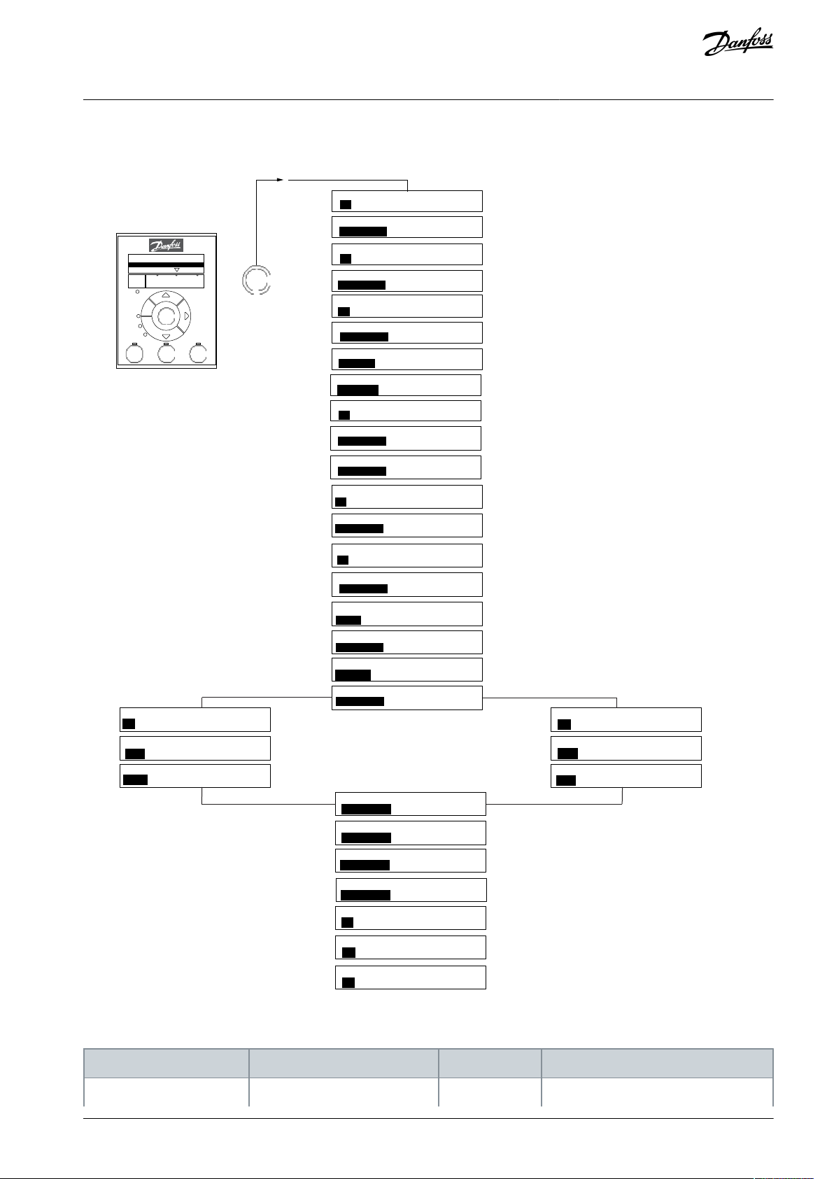
4.3.1.1 Programming via the Quick Menu
Procedure
1.
To enter the Quick Menu, press [Menu] until indicator in display is placed above Quick Menu.
2.
Press [▵] [▿] to select quick guide, closed-loop setup, compressor setup, or changes made, then press [OK].
3.
Press [▵] [▿] to browse through the parameters in the Quick Menu.
Press [OK] to select a parameter.
4.
Press [▵] [▿] to change the value of a parameter setting.
5.
Press [OK] to accept the change.
6.
7.
Press either [Back] twice to enter Status, or press [Menu] once to enter Main Menu.
4.3.1.2 Programming via the Main Menu
Procedure
AU356039245821 en-000201 / 130R0597 | 15Danfoss A/S © 2021.07
Page 16

... the Quick Guide starts
OK
press
Select Open Loop
Status
Main
Menu
Quick
Menu
Hand
On
OK
Menu
Reset
Off
Auto
On
Alarm
Warn.
On
Open Loop
Compressor Function
Setup 1
B
a
c
k
Com.
e30bi585.10
0-06 Grid Type
0-60 Main Menu Password
Size related
0
Size related
1-13 Compressor Selection
200.000
3-03 Maximum Reference
[1]
3-15 Reference 1 Source
Analog Input 53
Size related
3-41 Ramp 1 Ramp Up Time
Size related
3-42 Ramp 1 Ramp Down Time
[2]
5-12 Terminal 27 Digital Input
Coast inverse
Size related
5-40 Function Relay
Size related
6-10 Terminal 53 Low Voltage
10.00
6-11 Terminal 53 High Voltage
V
[0]
8-01 PI Control Site
Digital and ctrl. word
[0]
8-30 Protocol
FC
[2]
8-32 Baud
9600
0-01 Language
[0]
English
VLT® Compressor Drive CDS 803
Programming Guide
1.
Press [Menu] until indicator in display is placed above Main Menu.
2.
Press [▲] [▼] to browse through the parameter groups.
3.
Press [OK] to select a parameter group.
4.
Press [▲] [▼] to browse through the parameters in the specific group.
5.
Press [OK] to select the parameter.
6.
Press [▲] [▼] to set/change the parameter value.
7.
Press [OK] to accept the change or press [Back] to go back to the previous level.
4.3.2 Status Menu
In the Status menu, view the following:
•
Motor frequency [Hz], parameter 16-13 Frequency.
•
Motor current [A], parameter 16-14 Motor current.
•
Motor speed reference in percentage [%], parameter 16-02 Reference [%].
•
Feedback, parameter 16-52 Feedback [Unit].
•
Motor power parameter 16-10 Power [kW].
•
Custom readout parameter 16-09 Custom Readout.
4.3.3 Quick Menu
Use the Quick Menu to program the most common functions. The Quick Menu consists of:
Quick menu for open-loop applications.
•
Compressor functions.
•
Closed-loop setup quick menu.
•
Changes made.
•
Programming
4.3.3.1 The Start-up Quick Guide for Compressor Open-loop Applications
Illustration 4: Smart Guide for Open-loop Applications
AU356039245821 en-000201 / 130R059716 | Danfoss A/S © 2021.07
Page 17

Parameter
Option
Default
Function
Parameter 0-01 Language
[0] English
[1] Deutsch
[2] Français
[3] Dansk
[4] Español
[5] Italiano
[28] Bras.port
[0] English
Select the language for the display.
Parameter 0-06 GridType
[0] 200–240 V/50 Hz/IT-grid
[1] 200–240 V/50 Hz/Delta
[2] 200–240 V/50 Hz
[10] 380–440 V/50 Hz/IT-grid
[11] 380–440 V/50 Hz/Delta
[12] 380–440 V/50 Hz
[20] 440–480 V/50 Hz/IT-grid
[21] 440–480 V/50 Hz/Delta
[22] 440–480 V/50 Hz
[100] 200–240 V/60 Hz/IT-grid
[101] 200–240 V/60 Hz/Delta
[102] 200–240 V/60 Hz
[110] 380–440 V/60 Hz/IT-grid
[111] 380–440 V/60 Hz/Delta
[112] 380–440 V/60 Hz
[120] 440–480 V/60 Hz/IT-grid
[121] 440–480 V/60 Hz/Delta
[122] 440–480 V/60 Hz
Size related
Select operating mode for restart after
reconnection of the drive to mains voltage after power-down.
Parameter 0-60 Main Menu
Password
0–999
0
Define the password for access to the
LCP.
Parameter 1-13 Compressor Selection
6–10 kW
[24] VZH028-R410A
[25] VZH035-R410A
[26] VZH044-R410A
[27] VLZ028
[28] VLZ035
[29] VLZ044
Size related
Select which compressor to use.
Parameter 1-13 Compressor Selection
18–30 kW
[21] VZH088-R410A
[22] VZH117-R410A
[23] VZH170-R410A
[30] VZH088-R452B
[31] VZH088-R454B
[32] VZH117-R452B
[33] VZH117-R454B
[34] VZH170-R452B
[35] VZH170-R454B
Parameter 3-03 Maximum Reference
0–200 Hz
200 Hz
The maximum reference is the highest
obtainable by summing all references.
VLT® Compressor Drive CDS 803
Programming Guide
Table 6: Open-loop Applications Set-up
Programming
AU356039245821 en-000201 / 130R0597 | 17Danfoss A/S © 2021.07
Page 18

Parameter
Option
Default
Function
Parameter 3-15 Reference 1
Source
[0] No function
[1] Analog in 53
[2] Analog in 54
[7] Pulse input 29
[11] Local bus reference
[1] Analog in
53
Select the input to be used for the reference signal.
Parameter 3-41 Ramp 1 Ramp
Up Time
0.05–3600.0 s
Size related
Ramp-up time from 0 to parameter 1-25
Motor Nominal Speed.
Parameter 3-42 Ramp 1 Ramp
Down Time
0.05–3600.0 s
Size related
Ramp-down time from nominal motor
speed to 0.
Parameter 5-12 Terminal 27
Digital Input
[0] No operation
[1] Reset
[2] Coast inverse
[3] Coast and reset inverse
[4] Quick stop inverse
[5] DC-brake inverse
[6] Stop inverse
[7] External Interlock
[8] Start
[9] Latched start
[10] Reversing
[11] Start reversing
[14] Jog
[16] Preset ref bit 0
[17] Preset ref bit 1
[18] Preset ref bit 2
[19] Freeze reference
[20] Speed up
[22] Speed down
[23] Set-up select bit 0
[34] Ramp bit 0
[52] Run permissive
[53] Hand start
[54] Auto start
[60] Counter A (up)
[61] Counter A (down)
[62] Reset Counter A
[63] Counter B (up)
[64] Counter B (down)
[65] Reset Counter B
[2] Coast inverse
Select the input function for terminal 27.
Parameter 5-40 Function Relay
[0] Function relay
See parameter 5-40 Function Relay
Size related
Select the function to control output relay 1.
Parameter 5-40 Function Relay
[1] Function relay
See parameter 5-40 Function Relay
Drive running
Select the function to control output relay 2.
Parameter 6-10 Terminal 53 Low
Voltage
0–10 V
Size related
Enter the voltage that corresponds to
the low reference value.
VLT® Compressor Drive CDS 803
Programming Guide
Programming
AU356039245821 en-000201 / 130R059718 | Danfoss A/S © 2021.07
Page 19

Parameter
Option
Default
Function
Parameter 6-11 Terminal 53
High Voltage
0–10 V
10 V
Enter the voltage that corresponds to
the high reference value.
Parameter 8-01 Control Site
[0] Digital and ctrl.word
[1] Digital only
[2] Controlword only
[0] Digital and
ctrl. word
Select if digital, bus, or a combination of
both should control the drive.
Parameter 8-30 Protocol
[0] FC
[2] Modbus RTU
[0] FC
Select the protocol for the integrated
RS485 port.
Parameter 8-32 Baud Rate
[0] 2400 Baud
[1] 4800 Baud
[2] 9600 Baud
[3] 19200 Baud
[4] 38400 Baud
[5] 57600 Baud
[6] 76800 Baud
[7] 115200 Baud
9600
Select the baud rate for the RS485 port.
28-01 Interval between Starts
e30bd874.14
28-02 Minimum Run Time
28-00 Short Cycle Protection
[1] Enabled
28-10 Oil Return Management
[1] On
300 s
Size related
28-12 Fixed Boost Interval
28-13 Boost Duration
60 s
28-17 ORM Boost Speed [Hz]
OK
press
Select Compressor Function
Status
Main
Menu
Quick
Menu
Hand
On
OK
Menu
Reset
Off
Auto
On
Alarm
Warn.
On
Open Loop
Compressor Function
Setup 1
B
a
c
k
Com.
... the Quick Guide starts
Size related
Size related
Parameter
Option
Default
Function
Parameter 28-00 Short Cycle Protection
[0] Disabled
[1] Enabled
[1] Enabled
Select if short cycle protection is to be used.
Parameter 28-01 Interval between Starts
0–3600 s
300 s
Enter the minimum allowed time between starts.
Parameter 28-02 Minimum Run Time
10–3600 s
Size related
Enter the minimum allowed time to run before stop.
Parameter 28-10 Oil Return Management
[0] Off
[1] On
[1] On
Select if oil return management is to be used.
VLT® Compressor Drive CDS 803
Programming Guide
Programming
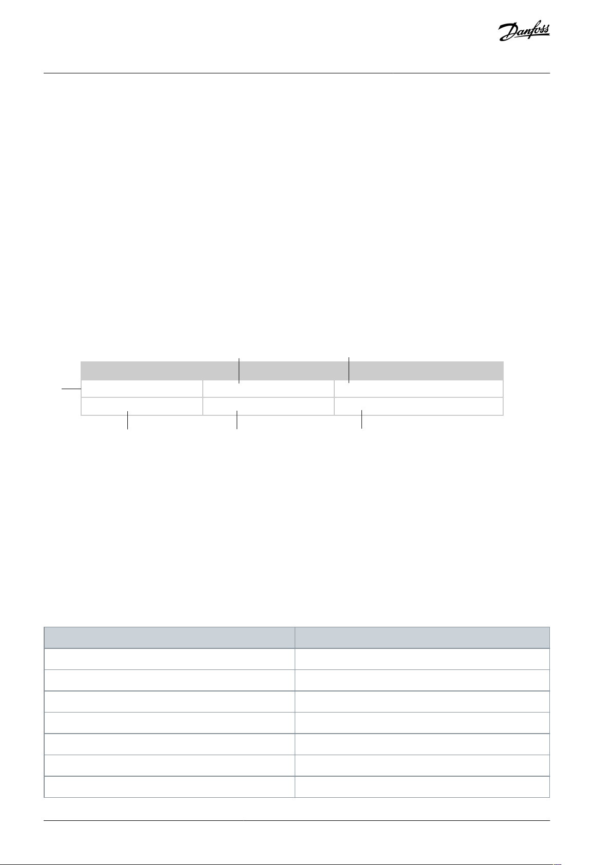
4.3.3.2 Compressor Functions Quick Guide
Illustration 5: Quick Guide for Compressor Functions
Table 7: Compressor Functions
AU356039245821 en-000201 / 130R0597 | 19Danfoss A/S © 2021.07
Page 20

Parameter
Option
Default
Function
Parameter 28-12 Fixed Boost Interval
1–168 h
Size related
Oil Boosts is performed at fixed time intervals
Parameter 28-13 Boost Duration
60–300 s
60 s
Enter the boost duration for the oil return.
Parameter 28-17 ORM Boost Speed [Hz]
80–200 Hz
Size related
Enter speed of the compressor during oil return boost.
VLT® Compressor Drive CDS 803
Programming Guide
Programming
AU356039245821 en-000201 / 130R059720 | Danfoss A/S © 2021.07
Page 21
e30bd875.13
0-01 Language
[0]
English
0-06 Grid Type
Size related
0-60 Main Menu Password
[0]
1-13 Compressor Selection
Size related
1-00 Configuration Mode
Open loop
[0]
3-02 Minimum Reference
Size related
3-03 Maximum Reference
200.000
3-10 Preset Reference
[0] 0.00 %
3-15 Reference 1 Source
Analog in 53
[1]
3-41 Ramp 1 Ramp Up Time3-41 Ramp 1 Ramp Up Time
5-12 Terminal 27 Digital Input
Coast inverse
[2]
5-12 Terminal 27 Digital Input
Coast inverse
[2]
5-40 Function Relay 1 5-40 Function Relay 1
6-19 Terminal 53 mode
Voltage mode
[1]
6-19 Terminal 53 mode
Voltage mode
[1]
6-10 Terminal 53 Low Voltage
6-10 Terminal 53 Low Voltage
6-11 Terminal 53 High Voltage
10.00
V
6-11 Terminal 53 High Voltage
10.00
V
6-14 Terminal 53 Low Ref./Feedb.
Size related
6-14 Terminal 53 Low Ref./Feedb.
Size related
6-15 Terminal 53 High Ref./Feedb.
200.000
Hz
6-15 Terminal 53 High Ref./Feedb.
200.000
6-29 Terminal 54 mode
Current mode
6-29 Terminal 54 mode
[0]
6-22 Terminal 54 Low Current
4.00
mA
6-22 Terminal 54 Low Current
4.00
mA
6-23 Terminal 54 High Current
20.00
mA
6-23 Terminal 54 High Current
20.00
mA
6-24 Terminal 54 Low Ref./Feedb.
0
0.000
6-24 Terminal 54 Low Ref./Feedb.
0
Size related
6-25 Terminal 54 High Ref./Feedb.
6-25 Terminal 54 High Ref./Feedb.
Size related
20-00 Feedback 1 Source 20-00 Feedback 1 Source
20-81 PI Normal/Inverse control
8-01 Control Site
Digital and ctrl.word
[0]
8-01 Control Site
Digital and ctrl.word
[0]
8-30 Protocol
[0]
FC
8-30 Protocol
[0]
FC
8-32 Baud
[2]
9600 Baud
8-32 Baud
[2]
9600 Baud
3-42 Ramp 1 Ramp Down Time
5
6-29 Terminal 54 mode
0.00
[1]
Voltage mode
6-20 Terminal 54 Low Voltage
1.00
V
6-21 Terminal 54 High Voltage
5.00
V
... the Quick Guide starts
OK
press
Select Closed Loop
Status
Main
Menu
Quick
Menu
Hand
On
OK
Menu
Reset
Off
Auto
On
Alarm
Warn.
On
Compressor Function
Closed Loop
Setup 1
B
a
c
k
Com.
Size related
Size related
Size related
Size related
6-29 Terminal 54 mode6-29 Terminal 54 mode
Size related
Size related
Size related
Parameter
Option
Default
Function
Parameter 0-01 Language
[0] English
0
Select the language for the display.
VLT® Compressor Drive CDS 803
Programming Guide
4.3.3.3 The Start-up Quick Guide for Compressor Closed-loop Applications
Illustration 6: Closed-loop Quick Guide
Table 8: Closed-loop Applications Setup
AU356039245821 en-000201 / 130R0597 | 21Danfoss A/S © 2021.07
Programming
Page 22

Parameter
Option
Default
Function
[1] Deutsch
[2] Français
[3] Dansk
[4] Spanish
[5] Italiano
[28] Bras.port
Parameter 0-06 GridType
[0] 200–240 V/50 Hz/IT-grid
[1] 200–240 V/50 Hz/Delta
[2] 200–240 V/50 Hz
[10] 380–440 V/50 Hz/IT-grid
[11] 380–440 V/50 Hz/Delta
[12] 380–440 V/50 Hz
[20] 440–480 V/50 Hz/IT-grid
[21] 440–480 V/50 Hz/Delta
[22] 440–480 V/50 Hz
[100] 200–240 V/60 Hz/IT-grid
[101] 200–240 V/60 Hz/Delta
[102] 200–240 V/60 Hz
[110] 380–440 V/60 Hz/IT-grid
[111] 380–440 V/60 Hz/Delta
[112] 380–440 V/60 Hz
[120] 440–480 V/60 Hz/IT-grid
[121] 440–480 V/60 Hz/Delta
[122] 440–480 V/60 Hz
Size related
Select the operating mode for restart after reconnection of the drive to mains
voltage after power-down.
Parameter 0-60 Main Menu
Password
0–999
0
Define the password for access to the
LCP.
Parameter 1-00 Configuration
Mode
[0] Open loop
[3] Closed loop
[0] Open loop
Select closed loop.
Parameter 1-13 Compressor
Selection
6–10 kW
[24] VZH028-R410A
[25] VZH035-R410A
[26] VZH044-R410A
[27] VLZ028
[28] VLZ035
[29] VLZ044
Size related
Select the compressor in use.
Parameter 1-13 Compressor
Selection
18–30 kW
[21] VZH088-R410A
[22] VZH117-R410A
[23] VZH170-R410A
[30] VZH088-R452B
[31] VZH088-R454B
[32] VZH117-R452B
[33] VZH117-R454B
[34] VZH170-R452B
[35] VZH170-R454B
Parameter 3-02 Minimum Reference
0–200 Hz
30 Hz (6–10 kW)
The minimum reference is the lowest value obtainable by summing all references.
VLT® Compressor Drive CDS 803
Programming Guide
Programming
AU356039245821 en-000201 / 130R059722 | Danfoss A/S © 2021.07
Page 23

Parameter
Option
Default
Function
50 Hz (18–
30 kW)
Parameter 3-03 Maximum
Reference
0–200 Hz
200 Hz
The maximum reference is the highest
obtainable by summing all references.
Parameter 3-10 Reference 1
Source
-100 – 100%
0%
Set up a fixed setpoint in preset reference
[0].
Parameter 3-15 Reference 1
Source
[0] No function
[1] Analog in 53
[2] Analog in 54
[7] Pulse input 29
[11] Local bus reference
[1] Analog in 53
Select the input to be used for the reference signal.
Parameter 3-41 Ramp 1 Ramp
Up Time
0.05–3600.0 s
90.00 s (6–
10 kW)
180.00 s (18–
30 kW)
Ramp-up time from 0 to parameter 1-25
Motor Nominal Speed.
Parameter 3-42 Ramp 1 Ramp
Down Time
0.05–3600.0 s
30.00 s (6–
10 kW)
180.00 s (18–
30 kW)
Ramp-down time from nominal motor
speed to 0.
Parameter 5-12 Terminal 27
Digital Input
[0] No operation
[1] Reset
[2] Coast inverse
[3] Coast and reset inverse
[4] Quick stop inverse
[5] DC-brake inverse
[6] Stop inverse
[7] External Interlock
[8] Start
[9] Latched start
[10] Reversing
[11] Start reversing
[14] Jog
[16] Preset ref bit 0
[17] Preset ref bit 1
[18] Preset ref bit 2
[19] Freeze reference
[20] Speed up
[22] Speed down
[23] Set-up select bit 0
[34] Ramp bit 0
[52] Run permissive
[53] Hand start
[54] Auto start
[60] Counter A (up)
[61] Counter A (down)
[62] Reset Counter A
[63] Counter B (up)
[2] Coast inverse
Select the input function for terminal 27.
VLT® Compressor Drive CDS 803
Programming Guide
Programming
AU356039245821 en-000201 / 130R0597 | 23Danfoss A/S © 2021.07
Page 24

Parameter
Option
Default
Function
[64] Counter B (down)
[65] Reset Counter B
Parameter 5-40 Function Relay [0] Function relay
See parameter 5-40 Function Relay
[9] Alarm (6–
10 kW)
[65] Comparator
5 (18–30 kW)
Select the function to control output relay 1.
Parameter 5-40 Function Relay [1] Function Relay
See parameter 5-40 Function Relay
Drive running
Select the function to control output relay 2.
Paraneter 6-19 Terminal 53
Mode
(1)
[0] Current mode
[1] Voltage mode
[1] Voltage
mode
Program terminal 53 to either current or
voltage.
Parameter 6-10 Terminal 53
Low Voltage
0–10 V
0.07 V (6–10 kW)
0 V (18–30 kW)
Enter the voltage that corresponds to the
low reference value.
Parameter 6-11 Terminal 53
High Voltage
0–10 V
10 V
Enter the voltage that corresponds to the
high reference value.
Parameter 6-14 Terminal 53
Low Ref./ Feedb. Value
-4999 – 4999
Size related
Enter the reference value that corresponds to the voltage set in parameter
6-10 Terminal 53 Low Voltage.
Parameter 6-15 Terminal 53
High Ref./ Feedb. Value
-4999 – 4999
200
Enter the reference value that corresponds to the voltage set in parameter
6-11 Terminal 53 High Voltage.
Parameter 6-29 Terminal 54
Mode
[0] Current mode
[1] Voltage mode
[0] Current
mode (6–10 kW)
[1] Voltage
mode (18–
30 kW)
Program terminal 54 to either current or
voltage.
Parameter 6-20 Terminal 54
Low Voltage
0–10 V
0.07 V (6–10 kW)
1 V (18–30 kW)
Enter the voltage corresponding to the
low reference value set in parameter 6-24
Terminal 54 Low Ref./Feedb. Value.
Parameter 6-21 Terminal 54
High Voltage
0–10 V
10 V (6–10 kW)
5 V (18–30 kW)
Enter the voltage corresponding to the
high reference value set in parameter Ter-
minal 54 High Ref./Feedb. Value.
Parameter 6-22 Terminal 54
Low Current
0.00–20.00 mA
4.00 mA
Enter the current that corresponds to the
low reference value.
Parameter 6-23 Terminal 54
High Current
0–10 V
10 V
Enter the current that corresponds to the
high reference value.
Parameter 6-24 Terminal 54
Low Ref./ Feedb. Value
-0.00–20.00 mA
Size related
Enter the reference value that corresponds to the current set in parameter
6-20 Terminal 54 Low Voltage.
Parameter 6-25 Terminal 54
High Ref./ Feedb. Value
-4999 – 4999
Size related
Enter the reference value that corresponds to the current set in parameter
6-21 Terminal 54 High Voltage.
VLT® Compressor Drive CDS 803
Programming Guide
Programming
AU356039245821 en-000201 / 130R059724 | Danfoss A/S © 2021.07
Page 25

Parameter
Option
Default
Function
Parameter 8-01 Control Site
[0] Digital and ctrl.word
[1] Digital only
[2] Controlword only
[0] Digital and
ctrl. word
Select if digital, bus, or a combination of
both should control the drive.
Parameter 8-30 Protocol
[0] FC
[2] Modbus RTU
[0] FC
Select the protocol for the integrated
RS485 port.
Parameter 8-32 Baud Rate
[0] 2400 Baud
[1] 4800 Baud
[2] 9600 Baud
[3] 19200 Baud
[4] 38400 Baud
[5] 57600 Baud
[6] 76800 Baud
[7] 115200 Baud
9600
Select the baud rate for the RS485 port.
Parameter 20-00 Feedback 1
Source
[0] No function
[1] Analog Input 53
[2] Analog Input 54
[3] Pulse input 29
[100] Bus Feedback 1
[101] Bus Feedback 2
[0] No function
Select which input to use as the source of
the feedback signal.
Parameter 20-01 Feedback 1
Conversion
[0] Linear
[1] Square root
[0] Linear
Select how to calculate the feedback.
VLT® Compressor Drive CDS 803
Programming Guide
Programming
1
When parameter 6-19 Terminal 53 Mode is [0] Current mode, the next parameters will be parameter 6-12 Terminal 53 Low Current and parameter 6-13
Terminal 53 High Current. When parameter 6-19 Terminal 53 Mode is [1] Voltage mode, the next parameters will be parameter 6-10 Terminal 53 Low
Voltage and parameter 6-11 Terminal 53 High Voltage. When parameter 6-29 Terminal 54 Mode is [0] Current mode, the next parameters will be parameter 6-22 Terminal 54 Low Current and parameter 6-23 Terminal 54 High Current. When parameter 6-29 Terminal 54 Mode is [1] Voltage, the next parame-
ters are parameter 6-20 Terminal 54 Low Voltage and parameter 6-21 Terminal 54 High Voltage.
4.3.3.4 Changes Made
Changes Made lists all parameters changed from default settings.
The list shows only parameters which have been changed in the current edit set-up.
•
Parameters which have been reset to default values are not listed.
•
•
The message Empty indicates that no parameters have been changed.
4.3.4 Main Menu
The Main Menu is used for programming all parameters. The Main Menu parameters can be accessed immediately unless a password
has been created via parameter 0-60 Main Menu Password. For most applications, it is not necessary to access the Main Menu parameters. The Quick Menu provides the simplest and quickest access to the typical required parameters.
4.4 Uploading and Downloading Parameter Settings
4.4.1 Data Transfer from Drive to LCP
Once the setup of a drive is complete, Danfoss recommends storing the data in the LCP or on a PC via VLT® Motion Control Tool
MCT 10.
Stop the compressor before performing this operation.
W A R N I N G
AU356039245821 en-000201 / 130R0597 | 25Danfoss A/S © 2021.07
Page 26

VLT® Compressor Drive CDS 803
Programming Guide
Procedure
1.
Go to parameter 0-50 LCP Copy.
2.
Press [OK].
3.
Select [1] All to LCP.
Press [OK].
4.
4.4.2 Data Transfer from LCP to Drive
Connect the LCP to another drive to copy the parameter settings to this drive as well.
W A R N I N G
Stop the compressor before performing this operation.
Procedure
1.
Go to parameter 0-50 LCP Copy.
2.
Press [OK].
3.
Select [2] All from LCP.
4.
Press [OK].
4.5 Restoring Factory Default Settings
There are 2 different ways of initializing the drive to factory default settings:
•
Via parameter 14-22 Operation Mode (this is the recommended way).
Two-finger initialization
•
Some parameters will not be reset, see more details in
4.5.2 Two-finger Initialization.
4.5.1 Recommended Initialization (via Parameter 14-22 Operation Mode) and
Programming
4.5.1 Recommended Initialization (via Parameter 14-22 Operation Mode)
Initialization of the drive to default settings (via parameter 14-22 Operation Mode)
Procedure
1.
Select parameter 14-22 Operation Mode.
Press [OK].
2.
3.
Select [2] Initialisation and press [OK].
Cut off the mains supply and wait until the display turns off.
4.
Reconnect the mains supply.
5.
The drive is now reset, except the following parameters:
Parameter 0-03 Regional Settings
Parameter 1-06 Clockwise Direction
Parameter 1-13 Compressor Selection
Parameter 4-18 Current Limit
Parameter 8-30 Protocol
Parameter 8-31 Address
Parameter 8-32 Baud Rate
Parameter 8-33 Parity / Stop Bits
Parameter 8-35 Minimum Response Delay
Parameter 8-36 Maximum Response Delay
Parameter 8-37 Maximum Inter-char delay
Parameter 15-00 Operating hours to parameter 15-05 Over Volt's
Parameter 15-03 Power Up's
Parameter 15-04 Over Temp's
Parameter 15-05 Over Volt's
AU356039245821 en-000201 / 130R059726 | Danfoss A/S © 2021.07
Page 27

VLT® Compressor Drive CDS 803
Programming Guide
Parameter 15-30 Alarm Log: Error Code
Parameter group 15-4* Drive identification parameters
4.5.2 Two-finger Initialization
Procedure
1.
Power off the drive.
2.
Press [OK] and [Menu].
3.
Power up the drive while still pressing the keys above for 10 s.
The drive is now reset, except the following parameters:
Parameter 1-06 Clockwise Direction
Parameter 15-00 Operating hours
Parameter 15-03 Power Up's
Parameter 15-04 Over Temp's
Parameter 15-05 Over Volt's
Parameter 15-30 Alarm Log: Error Code
Parameter group 15-4* Drive identification parameters
Initialization of parameters is confirmed by AL80 in the display after the power cycle.
Programming
AU356039245821 en-000201 / 130R0597 | 27Danfoss A/S © 2021.07
Page 28
2
5
6
1
3
4
e30bi709.10
Default value:
Parameter type:
Setup:
Conversion index:
Data type: Change during operation:
Parameter Number: Paramter Name
Conversion index
Conversion factor
100175
3600000
74
36007060671/6061000000
5
100000
VLT® Compressor Drive CDS 803
Parameter Descriptions and
Programming Guide
Functions
5 Parameter Descriptions and Functions
5.1 Introduction to Parameters
The * in parameter numbers indicates a group or subgroup of parameters for which the first 1 or 2 numbers are the same. For example, 0-** indicates the group of parameters that all start with 0. 0-0* indicates the subgroup of parameters that share the first 2
numbers, which are 0-0.
An asterisk (*) after an option number indicates the default option. For example, [0]* English is the default option for parameter 0-01
Language.
Organization of the parameter chapter
The VLT® Compressor DriveCDS 803 uses 2 different software version depending on the power range. The 6–10 kW drives use one
software version, while 18–30 kW drives use another software version. The chapter is split into the following 3 sections:
•
Common Parameters: This section contains all available parameters shared across all power ranges.
•
6–10 kW Specific Parameters: This section contains the parameters available only for 6–10 kW drives.
•
18–30 kW Specific Parameters: This section contains the parameters available only for 18–30 kW drives.
5.1.1 Reading the parameter table
This Programming Guide includes parameter and options tables. These descriptions explain how to read the parameter and options
tables.
Illustration 7: Parameter Table
1 indicates the value set in factory. Expressionlimit means the default value is not a fixed value and may link to power size and pa-
rameter dependency.
2 indicates whether the parameter type is option or range. Option means that the user is presented with a predefined selection to
choose between. Range means that the user can select any value within the specified range.
3 indicates the manner of parameter set-ups. 2 setups means that the parameter can be set individually in each of the 2 setups. For
example, 1 single parameter can have 2 different data values. 1 setup indicates that the data value is the same in all setups.
4 refers to the conversion index. Parameter values are transferred as whole numbers only. Conversion factors are therefore used to
transfer decimals. If a value is transferred as 100 and a conversion index of -1, the real value is 10.0.
5 indicates the different data types for the parameters.
6 indicates whether the parameter value can be changed while the drive is in operation. False indicates that the frequency convert-
er must be stopped before a change can be made.
Table 9: Conversion Table
AU356039245821 en-000201 / 130R059728 | Danfoss A/S © 2021.07
Page 29

Conversion index
Conversion factor
4
10000
3
1000210011001-10.1-20.01-30.001
-4
0.0001
-5
0.00001
-6
0.000001
Data type
Description
Type2Integer 8
Int83Integer 16
Int164Integer 32
Int325Unsigned 8
Uint8
6
Unsigned 16
Uint16
7
Unsigned 32
Uint32
9
Visible string
VisStr
33
Normalized value 2 bytes
N235Bit sequence of 16 boolean variables
V2
0-01 Language
Default value: English
Parameter type: Option
Setup: 1 setup
Conversion index: –
Data type: Uint8
Change during operation: True
VLT® Compressor Drive CDS 803
Programming Guide
Parameter Descriptions and
Functions
Table 10: Data type
5.2 Common Parameters
5.2.1 Parameter Group 0-** Operation and Display
5.2.1.1 Parameter Group 0-0* Basic Settings
Parameter 0-01 Language
Table 11: Parameter 0-01 Language
Defines the language to be used in the display.
AU356039245821 en-000201 / 130R0597 | 29Danfoss A/S © 2021.07
Page 30

Option
Name
Description
[0]*
English
[1]
Deutsch
[2]
Français
[3]
Dansk
[4]
Español
[5]
Italiano
[28]
Bras. Port
[255]
No text
0-04 Operating State at Power-up
Default value: Resume
Parameter type: Option
Setup: 2 setup
Conversion index: –
Data type: Uint8
Change during operation: True
Option
Name
Description
[0]*
Resume
Resumes operation of the drive, maintaining the same start/stop condition (applied by [Hand ON]/[Off]
on the LCP or local start via the digital input) as before the drive was powered down.
[1]
Forced
stop,
ref=old
Uses saved reference [1] to stop the drive, but at the same time retains the local speed reference in memory before powering down. After mains voltage is reconnected, and after receiving a start command
(pressing [Hand On] or using the local start command via a digital input), the drive restarts and operates
at the retained speed reference.
0-07 Auto DC Braking
Default value: On
Parameter type: Option
Setup: 1 setup
Conversion index: –
Data type: Uint8
Change during operation: False
Option
Name
Description
[0]
Off
This function is not active.
[1]*OnThis function is active.
VLT® Compressor Drive CDS 803
Programming Guide
Parameter 0-04 Operating State at Power-up
Table 12: Parameter 0-04 Operating State at Power-up
Parameter Descriptions and
Functions
Select the operating mode after recognition of the drive to mains voltage after power-down when operating in Hand (local) mode.
Parameter 0-07 Auto DC Braking
Table 13: Parameter 0-07 Auto DC Braking
Protective function against overvoltage at coast.
N O T I C E
Can cause PWM when coasted.
AU356039245821 en-000201 / 130R059730 | Danfoss A/S © 2021.07
Page 31

0-10 Active Set-up
Default value: Set-up 1
Parameter type: Option
Setup: 1 setup
Conversion index: –
Data type: Uint8
Change during operation: True
Option
Name
Description
[1]*
Set-up 1
Set-up 1 is active.
[2]
Set-up 2
Set-up 2 is active.
[9]
Multi Set-up
Used for remote setup selections via digital inputs and the serial communication port. This setup uses
the settings from parameter 0-12 Link Setups.
0-11 Programming Set-up
Default value: Active Set-up
Parameter type: Option
Setup: 1 setup
Conversion index: –
Data type: Uint8
Change during operation: False
Option
Name
Description
[1]
Set-up 1
Edit set-up 1.
[2]
Set-up 2
Edit set-up 2.
[9]*
Active Set-up
Edit parameters in the setup selected via digital I/Os.
0-12 Link Setups
Default value: Linked
Parameter type: Option
Setup: 2 setup
Conversion index: –
Data type: Uint8
Change during operation: False
Option
Name
Description
[0]
Not linked
When selecting a different setup for operation, the setup change does not occur until the compressor is
coasted.
[20]*
Linked
Copies Not changeable during operation parameters from one setup to the other. It is possible to switch
setup while the compressor is running.
VLT® Compressor Drive CDS 803
Programming Guide
5.2.1.2 Parameter Group 0-1* Set-up Operations
Parameter 0-10 Active Set-up
Table 14: Parameter 0-10 Active Set-up
Select the setup in which the drive operates.
Parameter Descriptions and
Functions
Parameter 0-11 Programming Set-up
Table 15: Parameter 0-11 Programming Set-up
The number of the setup being edited is shown flashing in the LCP.
Parameter 0-12 Link Setups
Table 16: Parameter 0-12 Link Setups
If the setups are not linked, a change between them is not possible while the compressor is running.
AU356039245821 en-000201 / 130R0597 | 31Danfoss A/S © 2021.07
Page 32

0-30 Custom Readout Unit
Default value: %
Parameter type: Option
Setup: 1 setup
Conversion index: –
Data type: Uint8
Change during operation: True
Option
Name
Description
[0]
None
[1]*%[5]
PPM
[10]
l/Min
[11]
RPM
[12]
Pulse/s
[20]
l/s
[21]
l/min
[22]
l/h
[23]
m3/s
[24]
m3/min
[25]
m3/h
[30]
kg/s
[31]
kg/min
[32]
kg/h
[33]
t/min
[34]
t/h
[40]
m/s
[41]
m/min
[45]m[60]
Degree Celsius
[70]
mbar
[71]
bar
[72]Pa[73]
kPa
VLT® Compressor Drive CDS 803
Parameter Descriptions and
Programming Guide
Functions
5.2.1.3 Parameter Group 0-3* LCP Custom Readout
Parameter 0-30 Custom Readout Unit
Table 17: Parameter 0-30 Custom Readout Unit
Program a value to be shown in the display of the LCP. The value has a linear, squared, or cubed relation to speed. This relation
depends on the unit selected. The actual calculated value can be read in parameter 16-09 Custom Readout.
AU356039245821 en-000201 / 130R059732 | Danfoss A/S © 2021.07
Page 33

Option
Name
Description
[74]
m Wg
[80]kW[120]
GPM
[121]
gal/s
[122]
gal/min
[123]
gal/h
[124]
CFM
[127]
ft3/h
[140]
ft/s
[141]
ft/min
[160]
Degree Fahr
[170]
psi
[171]
lb/in
2
[172]
in WG
[173]
ft WG
[180]
hp
0-31 Custom Readout Min Value
Default value: 0 CustomReadoutUnit
Parameter type: Range [0 - Expressionlimit (999999.99)]
Setup: 1 setup
Conversion index: –
Data type: Int32
Change during operation: True
0-32 Custom Readout Max Value
Default value: 100 CustomReadoutUnit
Parameter type: Range [0.0 - Expressionlimit
(999999.99)]
Setup: 1 setup
Conversion index: -2
Data type: Int32
Change during operation: True
VLT® Compressor Drive CDS 803
Programming Guide
Parameter Descriptions and
Functions
Parameter 0-31 Custom Readout Min Value
Table 18: Parameter 0-31 Custom Readout Min Value
This parameter sets the minimum value of the custom-defined readout (occurs at 0 speed). It is only possible to select a value different from 0 when selecting a linear unit in parameter 0-30 Custom Readout Unit. For quadric and cubic units, the minimum value is 0.
Parameter 0-32 Custom Readout Max Value
Table 19: Parameter 0-32 Custom Readout Max Value
This parameter sets the maximum value to be shown when the speed of the compressor has reached the value set for parameter
4-14 Motor Speed High Limit [Hz].
AU356039245821 en-000201 / 130R0597 | 33Danfoss A/S © 2021.07
Page 34

0-42 [Auto On] key on the LCP
Default value: Enabled
Parameter type: Option
Setup: 2 setups
Conversion index: –
Data type: Uint8
Change during operation: True
Option
Name
Description
[0]
Disabled
To avoid unintended start of the drive from the LCP, select [0] Disabled.
[1]*
Enabled
[Auto On] is enabled.
0-44 [Off/Reset] key on the LCP
Default value: Enabled
Parameter type: Option
Setup: 2 setups
Conversion index: –
Data type: Uint8
Change during operation: True
Option
Name
Description
[0]
Disabled
Disable the [Off/Reset] key.
[1]*
Enabled
Enable both off and reset functions.
[7]
Enable Reset Only
Enable the reset function and disable the off function to avoid unintended stop of the drive.
0-50 LCP Copy
Default value: No copy
Parameter type: Option
Setup: 1 setup
Conversion index: –
Data type: Uint8
Change during operation: False
Option
Name
Description
[0]*
No copy
[1]
All to LCP
Copies all parameters in all setups from the drive memory to the LCP memory. For service purposes,
to copy all parameters to the LCP after commissioning.
[2]
All from LCP
Copies all parameters in all setups from the LCP memory to the drive memory.
[3]
Size indep. from
LCP
Copies only the parameters that are independent of the compressor size. The latter selection can be
used to program several drives with the same function without disturbing compressor data which is
already set.
VLT® Compressor Drive CDS 803
Programming Guide
5.2.1.4 Parameter Group 0-4* LCP Keypad
Parameter 0-42 [Auto On] Key on LCP
Table 20: Parameter 0-42 [Auto On] key on the LCP
Parameter 0-44 [Off/Reset] Key on LCP
Table 21: Parameter 0-44 [Off/Reset] key on the LCP
Parameter Descriptions and
Functions
5.2.1.5 Parameter Group 0-5* Copy/Save
Copy parameter settings between setups and to/from the LCP.
Parameter 0-50 LCP Copy
Table 22: Parameter 0-50 LCP Copy
AU356039245821 en-000201 / 130R059734 | Danfoss A/S © 2021.07
Page 35

0-51 Set-up Copy
Default value: No copy
Parameter type: Option
Setup: 1 setup
Conversion index: –
Data type: Uint8
Change during operation: False
Option
Name
Description
[0]*
No copy
[1]
Copy from setup 1
Copy from setup 1 to setup 2.
[2]
Copy from setup 2
Copy from setup 2 to setup 1.
[9]
Copy from factory setup
Copy factory setting to programming setup (selected in parameter 0-11 Programming Set-
up).
0-60 Main Menu Password
Default value: 0
Parameter type: Range [0 - 999]
Setup: 1 setup
Conversion index: 0
Data type: Uint16
Change during operation: True
1-00 Configuration Mode
Default value: Open loop
Parameter type: Option
Setup: 2 setups
Conversion index: –
Data type: Uint8
Change during operation: True
Option
Name
Description
[0]*
Open loop
Compressor speed is determined by applying a speed reference or by setting speed when in hand-on
mode. Open loop is also used if the drive is part of a closed-loop control system based on an external PI
controller providing a speed reference signal as output.
[3]
Process
Control
Loop
Compressor speed is determined by a reference from the built-in PI controller varying the compressor
speed as of a closed-loop control process (for example, constant pressure or flow). Configure the PI controller in parameter group 20-** Drive Closed Loop.
VLT® Compressor Drive CDS 803
Programming Guide
Parameter 0-51 Set-up Copy
Table 23: Parameter 0-51 Set-up Copy
5.2.1.6 Parameter Group 0-6* Password
Parameter Descriptions and
Functions
Table 24: Parameter 0-60 Main Menu Password
Define the password for access to the Main Menu via the [Main Menu] key. Setting the value to 0 disables the password function.
5.2.2 Parameter Group 1-** Load and Motor
5.2.2.1 Parameter Group 1-0* General Settings
Parameter 1-00 Configuration Mode
Table 25: Parameter 1-00 Configuration Mode
Select which application control principle should be used.
N O T I C E
This parameter cannot be adjusted while the compressor is running.
AU356039245821 en-000201 / 130R0597 | 35Danfoss A/S © 2021.07
Page 36

1-71 Start Delay
Default value: 60 s
Parameter type: Range [0 - 120 s]
Setup: 2 setups
Conversion index: -1
Data type: Uint16
Change during operation: False
2-17 Over-voltage Control
Default value: Enabled
Parameter type: Option
Setup: 2 setups
Conversion index: –
Data type: Uint8
Change during operation: False
Option
Name
Description
[0]
Disabled
No OVC required.
[2]*
Enabled
Activates OVC.
N O T I C E
The ramp time is automatically adjusted to avoid tripping of the drive.
3-02 Minimum Reference
Default value: ExpressionLimit
Parameter type: Range [0 – 200 ReferenceFeedbackUnit]
Setup: 2 setups
Conversion index: -3
Data type: Int32
Change during operation: False
VLT® Compressor Drive CDS 803
Parameter Descriptions and
Programming Guide
Functions
5.2.2.2 Parameter Group 1-7* Start Adjustments
Parameters for configuring special motor start features.
Parameter 1-71 Start Delay
Table 26: Parameter 1-71 Start Delay
This parameter enables a delay of the starting time. The drive begins with the start function selected in parameter 1-72 Start Function. Set the start delay time until acceleration is to begin.
5.2.3 Parameter Group 2-** Brakes
5.2.3.1 Parameter Goup 2-1* Brake Energy Function
Parameter group for selecting dynamic brake parameters.
Parameter 2-17 Over-voltage Control
Table 27: Parameter 2-17 Over-voltage Control
Select whether to enable OVC during ramp down. Enabling OVC reduces the risk of a drive trip due to overvoltage on the DC link
caused by generative power from the load.
5.2.4 Parameter Group 3-** Reference/Ramps
5.2.4.1 Parameter Group 3-0* Reference Limits
Parameters for setting the reference unit, limits, and ranges.
Also see parameter group 20-0* Feedback for information on settings in closed loop.
Parameter 3-02 Minimum Reference
Table 28: Parameter 3-02 Minimum Reference
The minimum reference is the lowest value obtainable by summing all references.
AU356039245821 en-000201 / 130R059736 | Danfoss A/S © 2021.07
Page 37

3-03 Maximum Reference
Default value: 200 ReferenceFeedbackUnit
Parameter type: Range [0 – 200 ReferenceFeedbackUnit]
Setup: 2 setups
Conversion index: -3
Data type: Int32
Change during operation: False
P3-03
P3-02
0
50
100%
P3-10
e30bb036.11
3-10 Preset Reference
Default value: 0%
Parameter type: Range [-100 – 100%]
Setup: 2 setups
Conversion index: -2
Data type: Int16[8]
Change during operation: True
3-14 Preset Relative Reference
Default value: 0%
Parameter type: Range [-100 – 100%]
Setup: 2 setups
Conversion index: -2
Data type: Int16
Change during operation: True
VLT® Compressor Drive CDS 803
Parameter Descriptions and
Programming Guide
Parameter 3-03 Maximum Reference
Table 29: Parameter 3-03 Maximum Reference
The maximum reference is the highest value obtainable by summing all references. The maximum reference unit matches the configuration selected in parameter 1-00 Configuration Mode.
Functions
5.2.4.2 Parameter Group 3-1* References
Illustration 8: References
Parameter 3-10 References
Table 30: Parameter 3-10 Preset Reference
Enter up to 8 different preset references (0–7) in this parameter, using array programming. For selecting dedicated references, select
[16] Preset reference bit 0, [17] Preset reference bit 1, or [18] Preset reference bit 2 for corresponding digital inputs in parameter group
5-1* Digital Inputs.
Parameter 3-14 Preset Relative Reference
Table 31: Parameter 3-14 Preset Relative Reference
AU356039245821 en-000201 / 130R0597 | 37Danfoss A/S © 2021.07
Page 38

Relative
Z=X+X*Y/100
Resulting
actual
reference
Y
X
e30ba059.13
Z
X
100
%
0-100
Z
Y
X+X*Y/100
P 3-14
e30ba278.11
3-15 Reference 1 Source
Default value: Analog input 53
Parameter type: Option
Setup: 2 setups
Conversion index: –
Data type: Uint8
Change during operation: False
Option
Name
Description
[0]
No function
[1]*
Analog input 53
[2]
Analog input 54
[7]
Pulse input 29
[11]
Local bus reference
3-17 Reference 3 Source
Default value: Local bus reference
Parameter type: Option
Setup: 2 setups
Conversion index: –
Data type: Uint8
Change during operation: False
VLT® Compressor Drive CDS 803
Parameter Descriptions and
Programming Guide
The actual reference, X, is increased or decreased with the percentage, Y, set in this parameter. This results in the actual reference, Z.
Actual reference (X) is the sum of the inputs selected in parameter 3-15 Reference 1 Source, parameter 3-16 Reference 2 Source, param-
eter 3-17 Reference 3 Source, and parameter 8-02 Control Source.
Illustration 9: Preset Relative Reference
Functions
Illustration 10: Actual Reference
Parameter 3-15 Reference 1 Source
Table 32: Parameter 3-15 Reference 1 Source
Select the input to be used for the 1st reference signal. Parameters 3-15 to 3-17 define up to 3 difference reference signals. The sum
of these signals defines the actual reference.
Parameter 3-17 Reference 3 Source
Table 33: Parameter 3-17 Reference 3 Source
Select the input to be used for the 3rd reference signal. Parameters 3-15 to 3-17 define up to 3 difference reference signals. The sum
of these signals defines the actual reference.
AU356039245821 en-000201 / 130R059738 | Danfoss A/S © 2021.07
Page 39

Option
Name
Description
[0]
No function
[1]
Analog input 53
[2]
Analog input 54
[7]
Pulse input 29
[11]*
Local bus reference
t
a cc
t
dec
e30bb801.11
P 3-*2
R amp ( X)
D ow n
T ime (D ec)
P 4-14
H igh-limit
R PM
Reference
P 1-23
M ot or
fr equenc y
P 4-12
L o w limit
Time
P 3-*1
Ramp (X) Up
Time (Acc)
3-41 Ramp 1 Ramp Up Time
Default value: ExpressionLimit
Parameter type: Range [0.05 – 3600 s]
Setup: 2 setups
Conversion index: -2
Data type: Uint32
Change during operation: False
3-42 Ramp 1 Ramp Down Time
Default value: ExpressionLimit
Parameter type: Range [0.05 – 3600 s]
Setup: 2 setups
Conversion index: -2
Data type: Uint32
Change during operation: False
VLT® Compressor Drive CDS 803
Parameter Descriptions and
Programming Guide
Functions
5.2.4.3 Parameter Group 3-4* Ramp 1
Configure the ramp time parameters for each of the 2 ramps (parameter group 3-4* Ramp 1 and parameter group 3-5* Ramp 2). The
ramp time is preset to the minimum value of 10 ms for all power sizes.
Illustration 11: Ramps
Parameter 3-41 Ramp 1 Ramp Up Time
Table 34: Parameter 3-41 Ramp 1 Ramp Up Time
Enter acceleration time from 0 RPM to parameter 1-25 Motor Nominal Speed. Select a ramp-up time such that the output current
does not exceed the current limit in parameter 4-18 Current Limit during ramping. See ramp-down time in parameter 3-42 Ramp 1
Ramp Down Time.
Parameter 3-42 Ramp 1 Ramp Down Time
Table 35: Parameter 3-42 Ramp 1 Ramp Down Time
Enter deceleration time from parameter 1-25 Motor Nominal Speed to 0 RPM. Select a ramp-up time such that the output current
does not exceed the current limit in parameter 4-18 Current Limit during ramping. See ramp-up time in parameter 3-41 Ramp 1 Ramp
Up Time.
AU356039245821 en-000201 / 130R0597 | 39Danfoss A/S © 2021.07
Page 40

3-51 Ramp 2 Ramp Up Time
Default value: ExpressionLimit
Parameter type: Range [0.05 – 3600 s]
Setup: 2 setups
Conversion index: -2
Data type: Uint32
Change during operation: False
3-52 Ramp 2 Ramp Down Time
Default value: ExpressionLimit
Parameter type: Range [0.05 – 3600 s]
Setup: 2 setups
Conversion index: -2
Data type: Uint32
Change during operation: False
3-80 Jog Ramp Time
Default value: ExpressionLimit
Parameter type: Range [0.05 – 3600 s]
Setup: 2 setups
Conversion index: -2
Data type: Uint32
Change during operation: False
4-12 Motor Speed Low Limit [Hz]
Default value: ExpressionLimit
Parameter type: Range [0 – 200 Hz]
Setup: 2 setups
Conversion index: -1
Data type: Uint16
Change during operation: False
VLT® Compressor Drive CDS 803
Parameter Descriptions and
Programming Guide
Functions
5.2.4.4 Parameter Group 3-5* Ramp 2
This parameter group configures ramp 2 parameters.
Parameter 3-51 Ramp 2 Ramp Up Time
Table 36: Parameter 3-51 Ramp 2 Ramp Up Time
Enter acceleration time from 0 Hz to parameter 1-23 Motor Frequency if induction motor is selected. Enter acceleration time from
0 RPM to parameter 1-25 Motor Nominal Speed if PM motor is selected. Select a ramp-up time such that the output current does not
exceed the current limit in parameter 4-18 Current Limit during ramping. See ramp-down time in parameter 3-52 Ramp 2 Ramp Down
Time.
Parameter 3-52 Ramp 2 Ramp Down Time
Table 37: Parameter 3-52 Ramp 2 Ramp Down Time
Enter the ramp-down time from parameter 1-25 Motor Nominal Speed to 0 RPM. Select a ramp-down time such that no overvoltage
occurs in the inverter due to regenerative operation of the motor, and such that the generated current does not exceed the current
limit in parameter 4-18 Current Limit. See ramp-up time in parameter 3-51 Ramp 2 Ramp Up Time.
5.2.4.5 Parameter Group 3-8* Other Ramps
Parameter 3-80 Jog Ramp Time
Table 38: Parameter 3-80 Jog Ramp Time
Enter the jog ramp time, that is, the acceleration/deceleration time between 0 Hz to parameter 1-25 motor Nominal Speed. Ensure
that the resulting output current required for the given jog ramp does not exceed the current limit in parameter 4-18 Current Limit.
The jog ramp time starts after activation of a jog signal via the control panel, a selected digital input, or the serial communication
port.
5.2.5 Parameter Group 4-** Limits/Warnings
5.2.5.1 Parameter Group 4-1* Motor Limits
Define current and speed limits for the compressor and the reaction of the drive when the limits are exceeded.
Parameter 4-12 Motor Speed Low Limit [Hz]
Table 39: Parameter 4-12 Motor Speed Low Limit [Hz]
Enter the minimum limit for motor speed. The motor speed low limit can be set to correspond to the minimum output frequency of
the motor shaft. The speed low limit must not exceed the setting in parameter 4-14 Motor Speed High Limit [Hz].
AU356039245821 en-000201 / 130R059740 | Danfoss A/S © 2021.07
Page 41

4-14 Motor Speed High Limit [Hz]
Default value: ExpressionLimit
Parameter type: Range [30 – 200 Hz]
Setup: 2 setups
Conversion index: -1
Data type: Uint16
Change during operation: False
4-19 Max Output Frequency
Default value: ExpressionLimit
Parameter type: Range [0 – 400]
Setup: 2 setups
Conversion index: -1
Data type: Uint16
Change during operation: False
4-40 Warning Freq. Low
Default value: ExpressionLimit
Parameter type: Range [0 – 500]
Setup: 2 setups
Conversion index: -1
Data type: Uint16
Change during operation: False
4-41 Warning Freq. High
Default value: ExpressionLimit
Parameter type: Range [0 – 500]
Setup: 2 setups
Conversion index: -1
Data type: Uint16
Change during operation: False
VLT® Compressor Drive CDS 803
Parameter Descriptions and
Programming Guide
Parameter 4-14 Motor Speed High Limit [Hz]
Table 40: Parameter 4-14 Motor Speed High Limit [Hz]
Enter the maximum limit for compressor speed. Parameter 4-14 Motor Speed High Limit [Hz] can be set to match the manufacturer's
recommended compressor speed. The motor speed high limit must exceed the value in parameter 4-12 Motor Speed Low Limit [Hz].
Functions
N O T I C E
Motor speed high limit cannot be set higher than parameter 4-19 Max Output Frequency.
Parameter 4-19 Max Output Frequency
Table 41: Parameter 4-19 Max Output Frequency
Enter the maximum output frequency value. Parameter 4-19 Max Output Frequency specifies the absolute limit on the drive output
frequency for improved safety in applications where accidental overspeeding must be avoided. This absolute limit applies to all
configurations and is independent of the setting in parameter 1-00 Configuration Mode.
5.2.5.2 Parameter Group 4-4* Adjustable Warnings 2
Parameter 4-40 Warning Freq. Low
Table 42: Parameter 4-40 Warning Freq. Low
Use this parameter to set a lower limit for the frequency range. When the compressor speed drops below this limit, the display reads
SPEED LOW. Warning bit 10 is set in parameter 16-94 Ext. Status Word. Output relay can be configured to indicate this warning. The
LCP warning light does not light when reaching the limit set in this parameter.
Parameter 4-41 Warning Freq. High
Table 43: Parameter 4-41 Warning Freq. High
Use this parameter to set an upper limit for the frequency range. When the compressor speed exceeds this limit, the display reads
SPEED HIGH. Warning bit 9 is set in parameter 16-94 Ext. Status Word. Output relay can be configured to indicate this warning. The
LCP warning light does not light when reaching the limit set in this parameter.
5.2.5.3 Parameter Group 4-5* Adjustable Warnings
Define adjustable warning limits for current. Warnings are shown on the display, programmed output, or fieldbus.
AU356039245821 en-000201 / 130R0597 | 41Danfoss A/S © 2021.07
Page 42

4-50 Warning Current Low
Default value: 0 A
Parameter type: Range [0 – 500 A]
Setup: 2 setups
Conversion index: -2
Data type: Uint32
Change during operation: False
4-51 Warning Current High
Default value: 0 A
Parameter type: Range [0 – 500 A]
Setup: 2 setups
Conversion index: -2
Data type: Uint32
Change during operation: False
4-61 Bypass Speed From [Hz]
Default value: 0 Hz
Parameter type: Range [0 – 500 Hz]
Setup: 2 setups
Conversion index: -1
Data type: Uint16
Change during operation: False
4-63 Bypass Speed To [Hz]
Default value: 0 Hz
Parameter type: Range [0 – 500 Hz]
Setup: 2 setups
Conversion index: -1
Data type: Uint16
Change during operation: False
VLT® Compressor Drive CDS 803
Programming Guide
Parameter 4-50 Warning Current Low
Table 44: Parameter 4-50 Warning Current Low
Parameter Descriptions and
Functions
Enter the I
programmed to produce a signal on the digital output or the relay output.
Parameter 4-51 Warning Current High
Table 45: Parameter 4-51 Warning Current High
Enter the I
med to produce a signal on the digital output or the relay output.
value. When the compressor current drops below this limit, a bit in the status word is set. This value can also be
LOW
value. When the compressor current exceeds this limit, a bit in the status word is set. This value can also be program-
HIGH
5.2.5.4 Parameter Group 4-6* Speed Bypass
Define the speed bypass areas for the ramps. Three frequency ranges can be avoided.
Parameter 4-61 Bypass Speed From [Hz]
Table 46: Parameter 4-61 Bypass Speed From [Hz]
Some systems call for avoiding certain output speeds due to resonance problems in the system. Enter the lower limits of the speeds
to be avoided.
Parameter 4-63 Bypass Speed To [Hz]
Table 47: Parameter 4-63 Bypass Speed To [Hz]
Some systems call for avoiding certain output speeds due to resonance problems in the system. Enter the upper limits of the speeds
to be avoided.
5.2.6 Parameter Group 5-** Digital In/Out
5.2.6.1 Parameter Group 5-0* Digital I/O Mode
Parameters for configuring the input and output using NPN and PNP.
N O T I C E
This parameter cannot be adjusted while the compressor is running.
AU356039245821 en-000201 / 130R059742 | Danfoss A/S © 2021.07
Page 43

5-00 Digital Input Mode
Default value: PNP
Parameter type: Option
Setup: 1 setup
Conversion index: –
Data type: Uint8
Change during operation: False
Option
Name
Description
[0]*
PNP
Action on positive directional pulses (0). PNP systems are pulled down to GND.
[1]
NPN
Action on negative directional pulses (1). NPN systems are pulled up to +24 V internally in the drive.
Digital input
function
Description
[0] No operation
No reaction to signals transmitted to the terminal.
[1] Reset
Reset the drive after a TRIP/ALARM. Trip lock alarms can be reset.
[2] Coast inverse
Leaves the compressor in free mode. Logic 0⇒coast stop.
[3] Coast and reset inverse
Reset and coast stop inverted input (NC). Leaves the compressor in free mode and resets the drive. Logic
0⇒coast stop and reset.
[4] Quick stop
inverse
Inverted input (NC). Generates a stop in accordance with the quick stop ramp time set in parameter 3-81 Quick
Stop Ramp Time. After ramping down, the shaft is in free mode.
[5] DC-brake inverse
Inverted input for DC braking (NC). Stops the compressor by energizing it with DC current for a certain period,
see parameter 2-01 DC Brake Current. The function is only active when the value in parameter 2-02 DC Braking
Time is different from 0. This selection is not possible when parameter 1-10 Motor Construction is set to [1] PM
non-salient SPM.
[6] Stop inverse
Stop inverted function. Generates a stop function when selected terminals go from logic 1 to 0 (not latched).
Stop is performed according to the selected ramp time.
[7] External interlock
Same function as [2] Coast inverse, but this function generates the alarm message External fault on the display
when the terminal, which is programmed for [2] Coast inverse, is logic 0. The alarm message is also active via
digital outputs and relay outputs, if programmed for [7] External interlock. The alarm can be reset using a digital input, fieldbus, or the [Reset] key if the cause for the external interlock has been removed.
[8] Start
Select start for a start/stop command. Logic 1=start, logic 0=stop.
[9] Latched start
The compressor starts if a pulse is applied for minimum 2 ms. The compressor stops when [6] Stop inverse is
activated.
[10] Reversing
Change direction of compressor shaft rotation. Reversing signal only changes direction of rotation; it does not
activate the start function. Select [2] Both direction in parameter 4-10 Motor Speed Direction. 0=normal, 1=reversing.
[11] Start reversing
Use for start/stop and for reversing at the same time. Signals on [8] Start are not allowed at the same time.
0=stop, 1=start reversing.
[14] Jog
Used for activating jog speed. See parameter 3-11 Jog Speed [Hz].
VLT® Compressor Drive CDS 803
Parameter Descriptions and
Programming Guide
Table 48: Parameter 5-00 Digital Input Mode
Set NPN or PNP mode for digital inputs 18, 19, 27, and 29. Digital input mode.
Functions
5.2.6.2 Parameter Group 5-1* Digital Inputs
Parameters for configuring the input functions for the input terminals. The digital inputs are used for selecting various functions in
the drive. All digital inputs can be set to the following functions:
Table 49: Digital Input Functions
AU356039245821 en-000201 / 130R0597 | 43Danfoss A/S © 2021.07
Page 44

Digital input
function
Description
[16] Preset ref
bit 0
Enables a selection between 1 of the 8 preset references according to Table 50.
[17] Preset ref
bit 1
Enables a selection between 1 of the 8 preset references according to Table 50.
[18] Preset ref
bit 2
Enables a selection between 1 of the 8 preset references according to Table 50.
[19] Freeze reference
Freeze the actual reference. The frozen reference is now the point of enable/condition for [21] Speed up and
[22] Speed down to be used. If speed up/down is used, speed change always follows ramp 2 (parameter 3-51
Ramp 2 Ramp Up Time and parameter 3-52 Ramp 2 Ramp Down Time in the range parameter 3-02 Minimum
Reference–parameter 3-03 Maximum Reference.
[20] Freeze output
Freeze the actual output. The frozen output is now the point of enable/condition for [21] Speed up and [22]
Speed down to be used. If speed up/down is used, speed change always follows ramp 2 (parameter 3-51 Ramp
2 Ramp Up Time and parameter 3-52 Ramp 2 Ramp Down Time in the range parameter 3-02 Minimum Reference–parameter 3-03 Maximum Reference.
[21] Speed up
Select this option for digital control of the up/down speed. Activate this function by selecting either [19]
Freeze reference or [20] Freeze output. When [21] Speed up is activated for less than 400 ms, the resulting reference is increased by 0.1%. If [21] Speed up is activated for more than 400 ms, the resulting reference ramps
according to ramp 1 in parameter 3-41 Ramp 1 Ramp Up Time.
[22] Speed
down
Same function as [21] Speed up, but the reference decreases.
[23] Set-up select bit 0
Selects 1 of the 2 setups. Set parameter 0-10 Active Set-up to [9] Multi set-up.
[32] Pulse input
Select [32] Pulse input when using a pulse sequence as either reference or feedback. Scaling is done in param-
eter group 5-5* Pulse Input. Available only on terminal 29.
[34] Ramp bit 0
Select which ramp to use. Logic 0 selects ramp 1 while logic 1 selects ramp 2.
[52] Run permissive
The input terminal, for which [52] Run Permissive has been programmed, must be logic 1 before a start command can be accepted. [52] Run permissive has a logic AND function related to the terminal which is programmed for [8] Start, [14] Jog, or [20] Freeze output. To start running the compressor, both conditions must be
fulfilled. If [52] Run permissive is programmed on multiple terminals, it only has to be logic 1 on 1 of the terminals for the function to be carried out. The digital output signal for Run Request ([8] Start, [14] Jog, or [20]
Freeze output) programmed in parameter group 5-4* Relays is not affected by [52] Run permissive.
N O T I C E
If no [52] Run permissive signal is applied but either run, jog, or freeze commands are activated, the status
line in the display shows either Run Requested, Jog Requested, or Freeze Requested.
[53] Hand start
A signal applied puts the drive into Hand mode as if [Hand On] had been pressed and a normal stop command is overridden. If disconnecting the signal, the compressor stops. To make any other start commands
valid, another digital input must be assigned to [54] Auto Start and a signal applied to this. The [Hand On] and
[Auto On] keys have no impact. The [Off] key overrides [53] Hand start and [54] Auto start. Press either [Hand
On] or [Auto On] to make [53] Hand start and [54] Auto start active again. If there is no signal on [53] Hand start
or [54] Auto start, the compressor stops regardless of any normal start command applied. If a signal is applied
to both [53] Hand start and [54] Auto start, the function is Auto start.
[54] Auto start
A signal applied puts the drive into Auto mode as if [Auto On] had been pressed. See also [53] Hand start.
[60] Counter A
(up)
Input for increment counting in the SLC counter.
VLT® Compressor Drive CDS 803
Programming Guide
Parameter Descriptions and
Functions
AU356039245821 en-000201 / 130R059744 | Danfoss A/S © 2021.07
Page 45
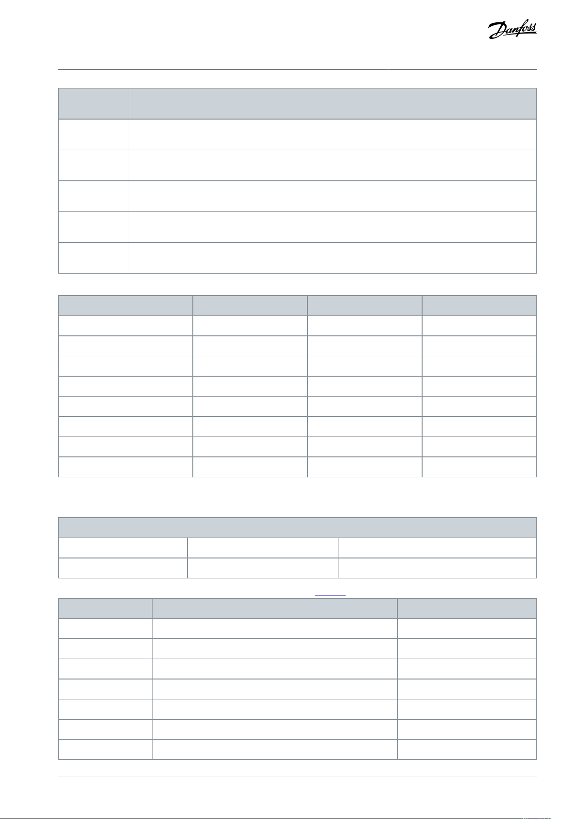
Digital input
function
Description
[61] Counter A
(down)
Input for decrement counting in the SLC counter.
[62] Reset counter A
Input for reset of counter A.
[63] Counter B
(up)
Input for increment counting in the SLC counter.
[64] Counter B
(down)
Input for decrement counting in the SLC counter.
[65] Reset counter B
Input for reset of counter B.
Selected preset reference
Preset reference bit 2
Preset reference bit 1
Preset reference bit 0
Preset reference 0
000
Preset reference 1
001
Preset reference 2
010
Preset reference 3
011
Preset reference 4
100
Preset reference 5
101
Preset reference 6
110
Preset reference 7
111
5-10 Terminal 18 Digital Input
Default value: Start
Parameter type: Option
Setup: 2 setups
Conversion index: –
Data type: Uint8
Change during operation: False
Option
Name
Description
[0]
No operation
[1]
Reset
[2]
Coast inverse
[3]
Coast and reset inverse
[4]
Quick stop inverse
[5]
DC-brake inverse
[6]
Stop inverse
VLT® Compressor Drive CDS 803
Programming Guide
Table 50: Selected Preset References
Parameter Descriptions and
Functions
Parameter 5-10 Terminal 18 Digital Input
Table 51: Parameter 5-10 Terminal 18 Digital Input
Parameter for configuring the input function on input terminal 18. See Table 49 for descriptions of the functions.
AU356039245821 en-000201 / 130R0597 | 45Danfoss A/S © 2021.07
Page 46

Option
Name
Description
[7]
External interlock
[8]*
Start
[9]
Latched start
[10]
Reversing
[11]
Start reversing
[14]
Jog
[16]
Preset ref bit 0
[17]
Preset ref bit 1
[18]
Preset ref bit 2
[19]
Freeze reference
[20]
Freeze output
[21]
Speed up
[22]
Speed down
[23]
Set-up select bit 0
[34]
Ramp bit 0
[52]
Run permissive
[53]
Hand start
[54]
Auto start
[60]
Counter A (up)
[61]
Counter A (down)
[62]
Reset Counter A
[63]
Counter B (up)
[64]
Counter B (down)
[65]
Reset Counter B
5-11 Terminal 19 Digital Input
Default value: No operation
Parameter type: Option
Setup: 2 setups
Conversion index: –
Data type: Uint8
Change during operation: False
VLT® Compressor Drive CDS 803
Programming Guide
Parameter Descriptions and
Functions
Parameter 5-11 Terminal 19 Digital Input
Table 52: Parameter 5-11 Terminal 19 Digital Input
Parameter for configuring the input function on input terminal 19. See Table 49 for descriptions of the functions.
AU356039245821 en-000201 / 130R059746 | Danfoss A/S © 2021.07
Page 47

Option
Name
Description
[0]*
No operation
[1]
Reset
[2]
Coast inverse
[3]
Coast and reset inverse
[4]
Quick stop inverse
[5]
DC-brake inverse
[6]
Stop inverse
[7]
External interlock
[8]
Start
[9]
Latched start
[10]
Reversing
[11]
Start reversing
[14]
Jog
[16]
Preset ref bit 0
[17]
Preset ref bit 1
[18]
Preset ref bit 2
[19]
Freeze reference
[20]
Freeze output
[21]
Speed up
[22]
Speed down
[23]
Set-up select bit 0
[34]
Ramp bit 0
[52]
Run permissive
[53]
Hand start
[54]
Auto start
[60]
Counter A (up)
[61]
Counter A (down)
[62]
Reset Counter A
[63]
Counter B (up)
[64]
Counter B (down)
[65]
Reset Counter B
VLT® Compressor Drive CDS 803
Programming Guide
Parameter Descriptions and
Functions
AU356039245821 en-000201 / 130R0597 | 47Danfoss A/S © 2021.07
Page 48

5-12 Terminal 27 Digital Input
Default value: ExpressionLimit
Parameter type: Option
Setup: 2 setups
Conversion index: –
Data type: Uint8
Change during operation: False
Option
Name
Description
[0]
No operation
[1]
Reset
[2]
Coast inverse
[3]
Coast and reset inverse
[4]
Quick stop inverse
[5]
DC-brake inverse
[6]
Stop inverse
[7]
External interlock
[8]
Start
[9]
Latched start
[10]
Reversing
[11]
Start reversing
[14]
Jog
[16]
Preset ref bit 0
[17]
Preset ref bit 1
[18]
Preset ref bit 2
[19]
Freeze reference
[20]
Freeze output
[21]
Speed up
[22]
Speed down
[23]
Set-up select bit 0
[34]
Ramp bit 0
[52]
Run permissive
[53]
Hand start
[54]
Auto start
[60]
Counter A (up)
[61]
Counter A (down)
VLT® Compressor Drive CDS 803
Parameter Descriptions and
Programming Guide
Parameter 5-12 Terminal 27 Digital Input
Table 53: Parameter 5-12 Terminal 27 Digital Input
Parameter for configuring the input function on input terminal 27. See Table 49 for descriptions of the functions.
Functions
AU356039245821 en-000201 / 130R059748 | Danfoss A/S © 2021.07
Page 49

Option
Name
Description
[62]
Reset Counter A
[63]
Counter B (up)
[64]
Counter B (down)
[65]
Reset Counter B
5-40 Function Relay
Default value: ExpressionLimit
Parameter type: Option
Setup: 2 setups
Conversion index: –
Data type: Uint8 [2]
Change during operation: False
Option
Name
Description
[0]
No operation
Default for both relays.
[1]
Control ready
The control board receives supply voltage.
[2]
Drive ready
The drive is ready for operation and applies a supply signal on the control board.
[3]
Drive ready/remote
control
The drive is ready for operation in auto on-mode.
[4]
Standby/no warning
The drive is ready for operation. No start or stop command is given. No warnings are present.
[5]
Drive running
The compressor runs.
[6]
Running/no warning
The compressor runs and no warnings are present.
[7]
Run in range/no
warning
The compressor runs within programmed current ranges, see parameter 4-50 Warning Current
Low and parameter 4-51 Warning Current High. No warnings are present.
[8]
Run on ref/no warning
The compressor runs at reference speed and with no warnings.
[9]
Alarm
An alarm activates output.
[10]
Alarm or warning
An alarm or warning activates output.
[12]
Out of current range
The compressor current is outside the range set in parameter 4-50 Warning Current Low and
parameter 4-51 Warning Current High.
[13]
Below current, low
The compressor current is lower than set in parameter 4-50 Warning Current Low.
[14]
Above current, high
The compressor current is higher than set in parameter 4-51 Warning Current High.
[16]
Below speed, low
The drive output speed is lower than the limit set in parameter 4-40 Warning Freq. Low.
[17]
Above speed, high
The drive output speed is higher than the limit set in parameter 4-41 Warning Freq. High.
[19]
Below feedback, low
The feedback is lower than the limit set in parameter 4-56 Warning Feedback Low.
[20]
Above feedback,
high
The feedback is higher than the limit set in parameter 4-57 Warning Feedback High.
VLT® Compressor Drive CDS 803
Programming Guide
5.2.6.3 Parameter Group 5-4* Relays
Parameters for configuring the timing and the output functions for the relays.
Table 54: Parameter 5-40 Function Relay
Parameter Descriptions and
Functions
Select options to define the function of the relays. The selection of each mechanical relay is realized in an array parameter.
AU356039245821 en-000201 / 130R0597 | 49Danfoss A/S © 2021.07
Page 50

Option
Name
Description
[21]
Thermal warning
The thermal warning turns on when the temperature exceeds the limit in the compressor,
drive, or thermistor.
[22]
Ready, no thermal
warning
The drive is ready for operation and no overtemperature warning is present.
[23]
Remote, ready, no
thermal warning
The drive is ready for operation in Auto on mode, and no overtemperature warning is present.
[24]
Ready, voltage OK
The drive is ready for operation and mains voltage is within the specified voltage range.
[25]
Reverse
The compressor runs/is ready to run clockwise when logic=0 and counterclockwise when logic=1. The output changes when the reversing signal is applied.
[26]
Bus OK
Active communication (no timeout) via serial communication port.
[35]
External interlock
See 5.2.6.2 Parameter Group 5-1* Digital Inputs.
[36]
Control word bit 11
Bit 11 in the control word controls the relay.
[37]
Control word bit 12
Bit 12 in the control word controls the relay.
[41]
Below reference, low
The reference is lower than the limit set in parameter 4-54 Warning Reference Low.
[42]
Above ref, high
The reference is higher than the limit set in parameter 4-55 Warning Reference High.
[44]
Oil boost active
[45]
Bus control
The output is configured in parameter 5-90 Digital & Relay Bus Control.
[60]
Comparator 0
See parameter group 13-1* Comparators. If Comparator 0 is evaluated as true, the output goes
high. Otherwise, it is low.
[61]
Comparator 1
See parameter group 13-1* Comparators. If Comparator 1 is evaluated as true, the output goes
high. Otherwise, it is low.
[62]
Comparator 2
See parameter group 13-1* Comparators. If Comparator 2 is evaluated as true, the output goes
high. Otherwise, it is low.
[63]
Comparator 3
See parameter group 13-1* Comparators. If Comparator 3 is evaluated as true, the output goes
high. Otherwise, it is low.
[64]
Comparator 4
See parameter group 13-1* Comparators. If Comparator 4 is evaluated as true, the output goes
high. Otherwise, it is low.
[65]
Comparator 5
See parameter group 13-1* Comparators. If Comparator 5 is evaluated as true, the output goes
high. Otherwise, it is low.
[70]
Logic rule 0
See parameter group 13-4* Logic Rules. If Logic rule 0 is evaluated as true, the output goes high.
Otherwise, it is low.
[71]
Logic rule 1
See parameter group 13-4* Logic Rules. If Logic rule 1 is evaluated as true, the output goes high.
Otherwise, it is low.
[72]
Logic rule 2
See parameter group 13-4* Logic Rules. If Logic rule 2 is evaluated as true, the output goes high.
Otherwise, it is low.
[73]
Logic rule 3
See parameter group 13-4* Logic Rules. If Logic rule 3 is evaluated as true, the output goes high.
Otherwise, it is low.
[74]
Logic rule 4
See parameter group 13-4* Logic Rules. If Logic rule 4 is evaluated as true, the output goes high.
Otherwise, it is low.
VLT® Compressor Drive CDS 803
Programming Guide
Parameter Descriptions and
Functions
AU356039245821 en-000201 / 130R059750 | Danfoss A/S © 2021.07
Page 51

Option
Name
Description
[75]
Logic rule 5
See parameter group 13-4* Logic Rules. If Logic rule 5 is evaluated as true, the output goes high.
Otherwise, it is low.
[80]
SL digital output A
See parameter 13-52 SL Controller Action. The input goes high whenever the smart logic action
[38] Set dig. out. A high is executed. The input goes low whenever the smart logic [32] Action set
dig. out A low is executed.
[81]
SL digital output B
See parameter 13-52 SL Controller Action. The input goes high whenever the smart logic action
[39] Set dig. out. B high is executed. The input goes low whenever the smart logic [33] Action set
dig. out B low is executed.
[82]
SL digital output C
See parameter 13-52 SL Controller Action. The input goes high whenever the smart logic action
[40] Set dig. out. C high is executed. The input goes low whenever the smart logic [34] Action set
dig. out C low is executed.
[83]
SL digital output D
See parameter 13-52 SL Controller Action. The input goes high whenever the smart logic action
[41] Set dig. out. D high is executed. The input goes low whenever the smart logic [35] Action set
dig. out D low is executed.
[160]
No alarm
The output is high when no alarm is present.
[161]
Running reverse
The output is high when the drive runs counterclockwise (the logical product of the status bits
running AND reverse).
[165]
Local ref. active
The output is high when parameter 3-13 Reference Site=[2] Local or when parameter 3-13 Refer-
ence Site=[0] Linked to hand auto at the same time as the LCP is in hand-on mode.
[166]
Remote ref. active
The output is thigh when parameter 3-13 Reference Site is set to [0] Linked to hand auto or [1]
Remote while the LCP is in auto on-mode.
[167]
Start command active
The output is high when there is an active start command (that is, via digital input, bus connection, Hand on, or Auto on) and no stop command is active.
[168]
Drive in hand mode
The output is high when the drive is in hand-on mode (as indicated by the LED light above
[Hand On]).
[169]
Drive in auto mode
The output is high when the drive is in auto on-mode (as indicated by the LED light above [Auto On]).
[194]
Broken belt function
This function is only available for 18–30 kW compressor drives.
VLT® Compressor Drive CDS 803
Programming Guide
Parameter Descriptions and
Functions
5.2.6.4 Parameter Group 5-5* Pulse Input
The pulse input parameters are used to define an appropriate window for the impulse reference area by configuring the scaling and
filter settings for the pulse inputs. Set terminal 29 (parameter 5-13 Terminal 29 Digital Input) to [32] Pulse Input. If terminal 29 is used
as an input, set parameter 5-01 Terminal 27 Mode to [0] Input.
AU356039245821 en-000201 / 130R0597 | 51Danfoss A/S © 2021.07
Page 52

e30ba076.11
(RPM)
Ref.
Low freq.
P 5-50/
P 5-55
Input
(Hz)
High
ref.
value
P 5-53/
p 5-58
High freq.
P 5-51/
P 5-56
Low
ref.
value
P 5-52/
p 5-57
5-52 Term. 29 Low Ref./Feedb. Value
Default value: 0 Hz
Parameter type: Range [-4999 – 4999]
Setup: 2 setups
Conversion index: -3
Data type: Int32
Change during operation: False
5-53 Term. 29 High Ref./Feedb. Value
Default value: ExpressionLimit
Parameter type: Range [-4999 – 4999]
Setup: 2 setups
Conversion index: -3
Data type: Int32
Change during operation: False
6-00 Live Zero Timeout Time
Default value: 10 s
Parameter type: Range [1 – 99]
Setup: 2 setups
Conversion index: 0
Data type: Uint8
Change during operation: False
VLT® Compressor Drive CDS 803
Programming Guide
Illustration 12: Pulse Input
Parameter 5-52 Term. 29 Low Ref./Feedb. Value
Table 55: Parameter 5-52 Term. 29 Low Ref./Feedb. Value
Parameter Descriptions and
Functions
Enter the low reference value for the compressor shaft speed [RPM]. This is also the lowest feedback value. Select terminal 29 as a
digital input.
Parameter 5-53 Term. 29 High Ref./Feedb. Value
Table 56: Parameter 5-53 Term. 29 High Ref./Feedb. Value
Enter the high reference value [RPM] for the compressor shaft speed and the high feedback value. Select terminal 29 as a digital
input.
5.2.7 Parameter Group 6-** Analog In/Out
Parameter group for setting up the analog I/O configuration and the digital output.
The drive provides 2 analog inputs:
•
Terminal 53
•
Terminal 54
The analog inputs can be freely allocated to either voltage (0–10 V) or current input (0/4–20 mA).
5.2.7.1 Parameter Group 6-0* Analog I/O Mode
Parameter 6-00 Live Zero Timeout Time
Table 57: Parameter 6-00 Live Zero Timeout Time
AU356039245821 en-000201 / 130R059752 | Danfoss A/S © 2021.07
Page 53

6-01 Live Zero Timeout Function
Default value: Off
Parameter type: Option
Setup: 2 setups
Conversion index: –
Data type: Uint8
Change during operation: False
A nalog input
H igh R ef ./
F eedb . V alue'
L o w R ef ./
F eedb . V alue'
'L o w V oltage' or
'L o w C ur r en t'
'H igh V oltage' or
'H igh C ur r en t'
e30ba038.14
1 V
5 V
10 V
300
600
900
1200
1500
[V ]
150
P ar 6-xx
P ar 6-xx
P ar 6-xx
P ar 6-xx
Ref./Feedback
[RPM]
Option
Name
Description
[0]*
Off
[1]
Freeze
[2]
Stop
[3]
Jogging
[4]
Max. speed
[5]
Stop and trip
VLT® Compressor Drive CDS 803
Parameter Descriptions and
Programming Guide
Enter the timeout time.
Parameter 6-01 Live Zero Timeout Function
Table 58: Parameter 6-01 Live Zero Timeout Function
Select the timeout function. The function set in this parameter is activated if the input signal on terminal 53 or 54 is below 50% of
the value in parameter 6-10 Terminal 53 Low Voltage, parameter 6-12 Terminal 53 Low Current, parameter 6-20 Terminal 54 Low Voltage,
or parameter 6-22 Terminal 54 Low Current for a period defined in parameter 6-00 Live Zero Timeout Time.
Functions
Illustration 13: Live Zero Timeout Function
5.2.7.2 Parameter Group 6-1* Analog Input 53
Parameters for configuring the scaling and limits for analog input 53 (terminal 53).
AU356039245821 en-000201 / 130R0597 | 53Danfoss A/S © 2021.07
Page 54

6-11 Terminal 53 High Voltage
Default value: 10 V
Parameter type: Range [0 – 10 V]
Setup: 2 setups
Conversion index: -2
Data type: Uint16
Change during operation: False
6-12 Terminal 53 Low Current
Default value: 4 mA
Parameter type: Range [0 – 20 mA]
Setup: 2 setups
Conversion index: -5
Data type: Uint16
Change during operation: False
6-13 Terminal 53 High Current
Default value: 20 mA
Parameter type: Range [0 – 20 mA]
Setup: 2 setups
Conversion index: -5
Data type: Uint16
Change during operation: False
6-14 Terminal 53 Low Ref./Feedb. Value
Default value: ExpressionLimit
Parameter type: Range [-4999 – 4999]
Setup: 2 setups
Conversion index: -3
Data type: Int32
Change during operation: False
6-15 Terminal 53 High Ref./Feedb. Value
Default value: 200
Parameter type: Range [-4999 – 4999]
Setup: 2 setups
Conversion index: -3
Data type: Int32
Change during operation: False
VLT® Compressor Drive CDS 803
Parameter Descriptions and
Programming Guide
Parameter 6-11 Terminal 53 High Voltage
Table 59: Parameter 6-11 Terminal 53 High Voltage
Enter the voltage (V) that corresponds to the high reference value set in parameter 6-15 Terminal 53 High Ref./Feedb. Value.
Parameter 6-12 Terminal 53 Low Current
Table 60: Parameter 6-12 Terminal 53 Low Current
Enter the low current value. This reference signal corresponds to the low reference/feedback value that is set in parameter 6-14 Terminal 53 Low Ref./Feedb. Value. To activate parameter 6-01 Live Zero Timeout Function, set the value to >2 mA.
Parameter 6-13 Terminal 53 High Current
Functions
Table 61: Parameter 6-13 Terminal 53 High Current
Enter the high current value corresponding to the high reference/feedback set in parameter 6-15 Terminal 53 High Ref./Feedb. Value.
Parameter 6-14 Terminal 53 Low Ref./Feedb. Value
Table 62: Parameter 6-14 Terminal 53 Low Ref./Feedb. Value
Enter the reference or feedback value that corresponds to the voltage or current set in parameter 6-10 Terminal 53 Low Voltage and
parameter 6-12 Terminal 53 Low Current.
Parameter 6-15 Terminal 53 High Ref./Feedb. Value
Table 63: Parameter 6-15 Terminal 53 High Ref./Feedb. Value
Enter the reference or feedback value that corresponds to the voltage or current set in parameter 6-11 Terminal 53 High Voltage and
parameter 6-13 Terminal 53 High Current.
AU356039245821 en-000201 / 130R059754 | Danfoss A/S © 2021.07
Page 55

6-16 Terminal 53 Filter Time Constant
Default value: 0.01 s
Parameter type: Range [0.01 - 10 s]
Setup: 2 setups
Conversion index: -2
Data type: Uint16
Change during operation: False
6-19 Terminal 53 Mode
Default value: Voltage mode
Parameter type: Option
Setup: 1 setup
Conversion index: –
Data type: Uint8
Change during operation: False
Option
Name
Description
[0]
Current mode
Terminal 53 is set for current.
[1]*
Voltage mode
Terminal 53 is set for voltage.
6-22 Terminal 54 Low Current
Default value: 4 mA
Parameter type: Range [0 – 20 mA]
Setup: 2 setups
Conversion index: -5
Data type: Uint16
Change during operation: False
6-23 Terminal 54 High Current
Default value: 20 mA
Parameter type: Range [0 – 20 mA]
Setup: 2 setups
Conversion index: -5
Data type: Uint16
Change during operation: False
6-25 Terminal 54 High Ref./Feedb. Value
Default value: ExpressionLimit
Parameter type: Range [-4999 – 4999]
Setup: 2 setups
Conversion index: -3
Data type: Int32
Change during operation: False
VLT® Compressor Drive CDS 803
Parameter Descriptions and
Programming Guide
Parameter 6-16 Terminal 53 Filter Time Constant
Table 64: Parameter 6-16 Terminal 53 Filter Time Constant
Enter the time constant. This constant is a first-order digital low-pass filter time constant for suppressing electrical noise in terminal
53. A high time constant value improves dampening, but also increases the time delay through the filter.
Parameter 6-19 Terminal 53 Mode
Table 65: Parameter 6-19 Terminal 53 Mode
Functions
Select whether terminal 53 is used for current or voltage input.
5.2.7.3 Parameter Group 6-2* Analog Input 54
Parameters for configuring the scaling and limits for analog input 54 (terminal 54).
Parameter 6-22 Terminal 54 Low Current
Table 66: Parameter 6-22 Terminal 54 Low Current
Enter the low current value. This reference signal corresponds to the low reference/feedback value that is set in parameter 6-24 Terminal 54 Low Ref./Feedb. Value. To activate parameter 6-01 Live Zero Timeout Function, set the value to >2 mA.
Parameter 6-23 Terminal 54 High Current
Table 67: Parameter 6-23 Terminal 54 High Current
Enter the high current value corresponding to the high reference/feedback set in parameter 6-25 Terminal 54 High Ref./Feedb. Value.
Parameter 6-25 Terminal 54 High Ref./Feedb. Value
Table 68: Parameter 6-25 Terminal 54 High Ref./Feedb. Value
AU356039245821 en-000201 / 130R0597 | 55Danfoss A/S © 2021.07
Page 56

6-26 Terminal 54 Filter Time Constant
Default value: 0.01 s
Parameter type: Range [0.01 - 10 s]
Setup: 2 setups
Conversion index: -2
Data type: Uint16
Change during operation: False
6-70 Terminal 45 Mode
Default value: 0–20 mA
Parameter type: Option
Setup: 1 setup
Conversion index: –
Data type: Uint8
Change during operation: False
Option
Name
Description
[0]*
0–20 mA
[1]
4–20 mA
[2]
Digital output
6-71 Terminal 45 Analog Output
Default value: No operation
Parameter type: Option
Setup: 1 setup
Conversion index: –
Data type: Uint8
Change during operation: False
Option
Name
Description
[0]*
No operation
[100]
Output frequency
0–400 Hz
[101]
Reference
Min
ref
–Max
ref
[102]
Feedback
MinFB–Max
FB
[103]
Motor current
0–I
max
VLT® Compressor Drive CDS 803
Parameter Descriptions and
Programming Guide
Enter the reference or feedback value that corresponds to the voltage or current set in parameter 6-21 Terminal 54 High Voltage and
parameter 6-13 Terminal 53 High Current.
Parameter 6-26 Terminal 54 Filter Time Constant
Table 69: Parameter 6-26 Terminal 54 Filter Time Constant
Enter the time constant. This constant is a first-order digital low-pass filter time constant for suppressing electrical noise in terminal
54. A high time constant value improves dampening, but also increases the time delay through the filter.
Functions
5.2.7.4 Parameter Group 6-7* Analog/Digital Output 45
Parameters for configuring the scaling and limits for analog/digital output terminal 45. Analog outputs are current outputs: 0/4–
20 mA. Resolution on analog output is 12 bit. Analog output terminals can also be set up as digital output.
Parameter 6-70 Terminal 45 Mode
Table 70: Parameter 6-70 Terminal 45 Mode
Set terminal 45 to act as analog output or as digital output.
Parameter 6-71 Terminal 45 Analog Output
Table 71: Parameter 6-71 Terminal 45 Analog Output
Select the function of terminal 45 as an analog current output. See also parameter 6-70 Terminal 45 Mode.
AU356039245821 en-000201 / 130R059756 | Danfoss A/S © 2021.07
Page 57

Option
Name
Description
[106]
Power
0–P
nom
[139]
Bus control
0–100%
[254]
DC-link voltage
6-72 Terminal 45 Digital Output
Default value: No operation
Parameter type: Option
Setup: 1 setup
Conversion index: –
Data type: Uint8
Change during operation: False
Option
Name
Description
[0]*
No operation
[1]
Control ready
[2]
Drive ready
[3]
Drive ready/remote control
[4]
Standby/no warning
[5]
Drive running
[6]
Running/no warning
[7]
Run in range/no warning
[8]
Runn on ref/no warning
[9]
Alarm
[10]
Alarm or warning
[12]
Out of current range
[13]
Below current low
[14]
Above current, high
[16]
Below speed, low
[17]
Above speed, high
[19]
Below feedback, low
[20]
Above feedback, high
[21]
Thermal warning
[22]
Ready, no thermal warning
[23]
Remote, ready, no thermal warning
[24]
Ready, voltage OK
VLT® Compressor Drive CDS 803
Parameter Descriptions and
Programming Guide
Parameter 6-72 Terminal 45 Digital Output
Table 72: Parameter 6-72 Terminal 45 Digital Output
Select the function of terminal 45 as an digital current output. See also parameter 6-70 Terminal 45 Mode. See parameter 5-40 Function Relay for descriptions of the parameter options.
Functions
AU356039245821 en-000201 / 130R0597 | 57Danfoss A/S © 2021.07
Page 58

Option
Name
Description
[25]
Reverse
[26]
Bus OK
[35]
External interlock
[36]
Control word bit 11
[37]
Control word bit 12
[41]
Below reference, low
[42]
Above ref, high
[44]
Oil boost, active
[45]
Bus control
[60]
Comparator 0
[61]
Comparator 1
[62]
Comparator 2
[63]
Comparator 3
[64]
Comparator 4
[65]
Comparator 5
[70]
Logic rule 0
[71]
Logic rule 1
[72]
Logic rule 2
[73]
Logic rule 3
[74]
Logic rule 4
[75]
Logic rule 5
[80]
SL digital output A
[81]
SL digital output B
[82]
SL digital output C
[83]
SL digital output D
[160]
No alarm
[161]
Running reverse
[165]
Local ref. active
[166]
Remote ref. active
[167]
Start command active
VLT® Compressor Drive CDS 803
Programming Guide
Parameter Descriptions and
Functions
AU356039245821 en-000201 / 130R059758 | Danfoss A/S © 2021.07
Page 59

Option
Name
Description
[168]
Drive in hand mode
[169]
Drive in auto mode
[194]
Broken belt function
This option is only available in 18–30 kW drives.
6-73 Terminal 45 Output Min Scale
Default value: 0%
Parameter type: Range [0 - 200%]
Setup: 2 setups
Conversion index: -2
Data type: Uint16
Change during operation: False
6-74 Terminal 45 Output Max Scale
Default value: 100%
Parameter type: Range [0 - 200%]
Setup: 2 setups
Conversion index: -2
Data type: Uint16
Change during operation: False
6-76 Terminal 45 Output Bus Control
Default value: 0
Parameter type: Range [0 - 16384]
Setup: 2 setups
Conversion index: 0
Data type: Uint16
Change during operation: False
6-20 Terminal 42 Mode
Default value: 0–20 mA
Parameter type: Option
Setup: 1 setup
Conversion index: –
Data type: Uint8
Change during operation: False
VLT® Compressor Drive CDS 803
Parameter Descriptions and
Programming Guide
Parameter 6-73 Terminal 45 Output Min Scale
Table 73: Parameter 6-73 Terminal 45 Output Min Scale
Scale for the minimum output (0 mA or 4 mA) of the analog signal at terminal 45. Set the value to be the percentage of the full
range of the variable selected in parameter 6-71 Terminal 45 Analog Output.
Parameter 6-74 Terminal 45 Output Max Scale
Functions
Table 74: Parameter 6-74 Terminal 45 Output Max Scale
Scale for the maximum output (20 mA) of the analog signal at terminal 45. Set the value to be the percentage of the full range of the
variable selected in parameter 6-71 Terminal 45 Analog Output.
Parameter 6-76 Terminal 45 Output Bus Control
Table 75: Parameter 6-76 Terminal 45 Output Bus Control
Holds the level of analog output if controlled by bus.
5.2.7.5 Parameter Group 6-9* Analog/Digital Output 42
Parameters for configuring the limits for analog/digital output terminal 42. Analog outputs are current outputs: 0/4–20 mA. Resolution on analog outputs is 12 bits. Analog output terminals can also be set up as digital output.
Parameter 6-90 Terminal 42 Mode
Table 76: Parameter 6-90 Terminal 42 Mode
Set terminal 42 to act as analog output or as digital output.
AU356039245821 en-000201 / 130R0597 | 59Danfoss A/S © 2021.07
Page 60

Option
Name
Description
[0]*
0–20 mA
[1]
4–20 mA
[2]
Digital output
6-91 Terminal 42 Analog Output
Default value: No operation
Parameter type: Option
Setup: 1 setup
Conversion index: –
Data type: Uint8
Change during operation: False
Option
Name
Description
[0]*
No operation
[100]
Output frequency
0–100 Hz
[101]
Reference
Min
ref
–Max
ref
[102]
Feedback
MinFB–Max
FB
[103]
Motor current
0–I
max
[106]
Power
0–P
nom
[139]
Bus control
0–100%
[254]
DC-link voltage
6-92 Terminal 42 Digital Output
Default value: No operation
Parameter type: Option
Setup: 1 setup
Conversion index: –
Data type: Uint8
Change during operation: False
Option
Name
Description
[0]*
No operation
[1]
Control ready
[2]
Drive ready
[3]
Drive ready/remote control
[4]
Standby/no warning
[5]
Drive running
[6]
Running/no warning
VLT® Compressor Drive CDS 803
Parameter Descriptions and
Programming Guide
Parameter 6-91 Terminal 42 Analog Output
Table 77: Parameter 6-91 Terminal 42 Analog Output
Select the function of terminal 42 as an analog current output. See also parameter 6-90 Terminal 42 Mode.
Functions
Parameter 6-92 Terminal 42 Digital Output
Table 78: Parameter 6-92 Terminal 42 Digital Output
Select the function of terminal 45 as an digital current output. See also parameter 6-90 Terminal 42 Mode. See parameter 5-40 Function Relay for descriptions of the parameter options.
AU356039245821 en-000201 / 130R059760 | Danfoss A/S © 2021.07
Page 61

Option
Name
Description
[7]
Run in range/no warning
[8]
Runn on ref/no warning
[9]
Alarm
[10]
Alarm or warning
[12]
Out of current range
[13]
Below current low
[14]
Above current, high
[16]
Below speed, low
[17]
Above speed, high
[19]
Below feedback, low
[20]
Above feedback, high
[21]
Thermal warning
[22]
Ready, no thermal warning
[23]
Remote, ready, no thermal warning
[24]
Ready, voltage OK
[25]
Reverse
[26]
Bus OK
[35]
External interlock
[36]
Control word bit 11
[37]
Control word bit 12
[41]
Below reference, low
[42]
Above ref, high
[44]
Oil boost, active
[45]
Bus control
[60]
Comparator 0
[61]
Comparator 1
[62]
Comparator 2
[63]
Comparator 3
[64]
Comparator 4
[65]
Comparator 5
[70]
Logic rule 0
[71]
Logic rule 1
VLT® Compressor Drive CDS 803
Programming Guide
Parameter Descriptions and
Functions
AU356039245821 en-000201 / 130R0597 | 61Danfoss A/S © 2021.07
Page 62

Option
Name
Description
[72]
Logic rule 2
[73]
Logic rule 3
[74]
Logic rule 4
[75]
Logic rule 5
[80]
SL digital output A
[81]
SL digital output B
[82]
SL digital output C
[83]
SL digital output D
[160]
No alarm
[161]
Running reverse
[165]
Local ref. active
[166]
Remote ref. active
[167]
Start command active
[168]
Drive in hand mode
[169]
Drive in auto mode
[194]
Broken belt function
This option is only available in 18–30 kW drives.
6-93 Terminal 42 Output Min Scale
Default value: 0%
Parameter type: Range [0 - 200%]
Setup: 2 setups
Conversion index: -2
Data type: Uint16
Change during operation: False
6-94 Terminal 42 Output Max Scale
Default value: 100%
Parameter type: Range [0 - 200%]
Setup: 2 setups
Conversion index: -2
Data type: Uint16
Change during operation: False
VLT® Compressor Drive CDS 803
Programming Guide
Parameter Descriptions and
Functions
Parameter 6-93 Terminal 42 Output Min Scale
Table 79: Parameter 6-93 Terminal 42 Output Min Scale
Scale for the minimum output (0 mA or 4 mA) of the analog signal at terminal 42. Set the value to be the percentage of the full
range of the variable selected in parameter 6-91 Terminal 42 Analog Output.
Parameter 6-94 Terminal 42 Max Scale
Table 80: Parameter 6-94 Terminal 42 Output Max Scale
Scale for the maximum output (20 mA) of the analog signal at terminal 42. Set the value to be the percentage of the full range of the
variable selected in parameter 6-91 Terminal 42 Analog Output.
AU356039245821 en-000201 / 130R059762 | Danfoss A/S © 2021.07
Page 63
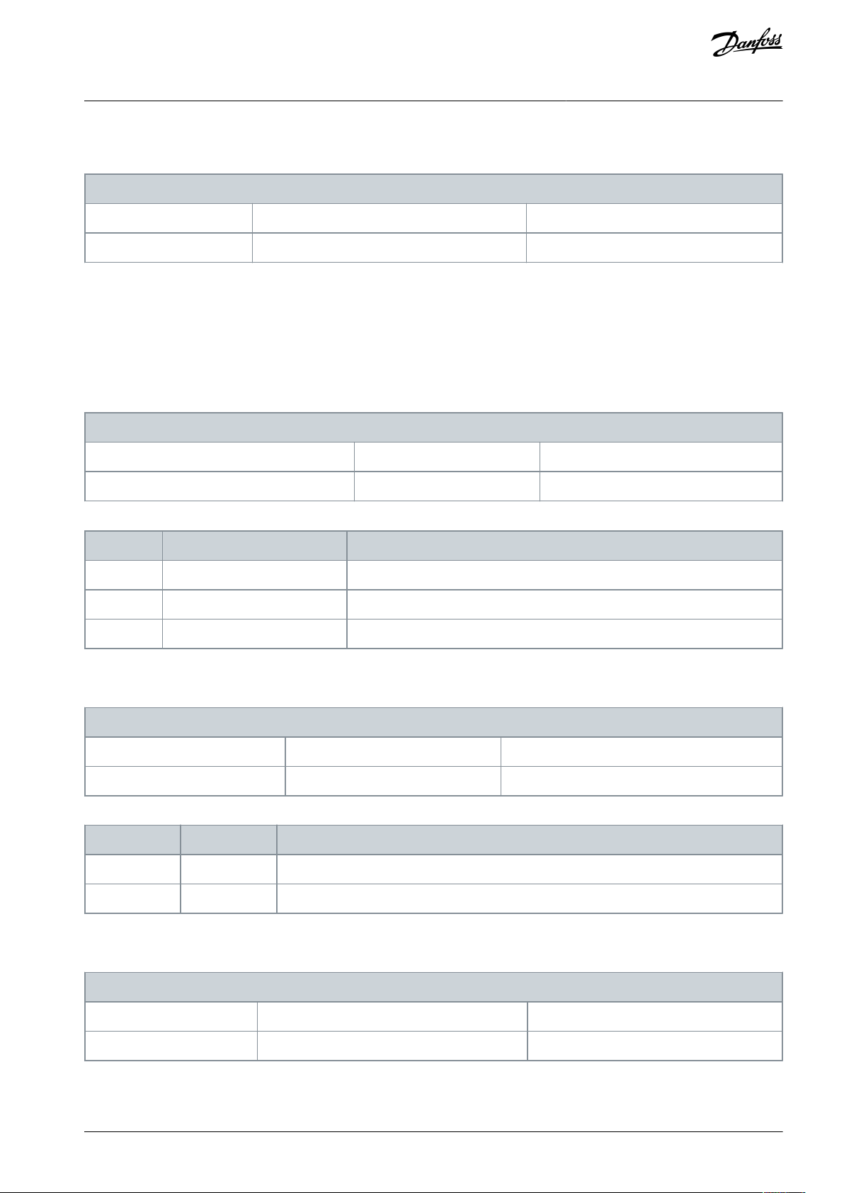
6-96 Terminal 42 Output Bus Control
Default value: 0
Parameter type: Range [0 - 16384]
Setup: 2 setups
Conversion index: 0
Data type: Uint16
Change during operation: False
8-01 Control Site
Default value: Digital and ctrl. word
Parameter type: Option
Setup: 2 setups
Conversion index: –
Data type: Uint8
Change during operation: False
Option
Name
Description
[0]*
Digital and ctrl. word
Control by using both digital input and control word.
[1]
Digital only
Control by using digital inputs only.
[2]
Controlword only
Control by using control word only.
8-02 Control Source
Default value: FC port
Parameter type: Option
Setup: 2 setups
Conversion index: –
Data type: Uint8
Change during operation: False
Option
Name
Description
[0]
None
No source has been selected for the control word.
[1]*
FC port
FC port is selected as source for the control word.
8-03 Control Timeout Time
Default value: 20 s
Parameter type: Range [0.1 – 200]
Setup: 1 setup
Conversion index: -1
Data type: Uint16
Change during operation: False
VLT® Compressor Drive CDS 803
Programming Guide
Parameter 6-96 Terminal 42 Output Bus Control
Table 81: Parameter 6-96 Terminal 42 Output Bus Control
Holds the level of analog output if controlled by bus.
5.2.8 Parameter Group 8-** Communications and Options
5.2.8.1 Parameter Group 8-0* General Settings
Parameter 8-01 Control Site
Table 82: Parameter 8-01 Control Site
Parameter Descriptions and
Functions
This parameter overrules settings in parameter 8-50 Coasting Select to parameter 8-56 Preset Reference Select.
Parameter 8-02 Control Source
Table 83: Parameter 8-02 Control Source
Select the source of the control word.
Parameter 8-03 Control Timeout Time
Table 84: Parameter 8-03 Control Timeout Time
Enter the maximum time expected to pass between the reception of 2 consecutive telegrams. If this time is exceeded, it indicates
that the serial communication has stopped. The function selected in parameter 8-04 Control Timeout Function is carried out.
AU356039245821 en-000201 / 130R0597 | 63Danfoss A/S © 2021.07
Page 64

8-30 Protocol
Default value: [0] FC
Parameter type: Option
Setup: 1 setup
Conversion index: –
Data type: Uint8
Change during operation: True
Option
Name
Description
[0]*FC[1]
Modbus RTU
8-31 Address
Default value: 1
Parameter type: Range [0.0 – 247]
Setup: 1 setup
Conversion index: 0
Data type: Uint8
Change during operation: False
8-32 Baud Rate
Default value: ExpressionLimit
Parameter type: Option
Setup: 1 setup
Conversion index: –
Data type: Uint8
Change during operation: False
Option
Name
Description
[0]
2400 Baud
[1]
4800 Baud
[2]
9600 Baud
[3]
19200 Baud
[4]
38400 Baud
[5]
57600 Baud
[6]
76800 Baud
[7]
115200 Baud
VLT® Compressor Drive CDS 803
Parameter Descriptions and
Programming Guide
Functions
5.2.8.2 Parameter Group 8-3* FC Port Settings
Parameter 8-30 Protocol
Table 85: Parameter 8-30 Protocol
Select the wanted protocol for the RS485 port. Change of protocol may change the baud rate.
N O T I C E
Altering between the supported communication protocols can be accessed and changed via the LCP as parameter 8-30 Protocol is
not available in VLT® Motion Control Tool MCT 10.
Parameter 8-31 Address
Table 86: Parameter 8-31 Address
Enter the address for the RS485 port. Valid range: 1–126 for FC port or 1–247 for Modbus.
Parameter 8-32 Baud Rate
Table 87: Parameter 8-32 Baud Rate
Select the baud rate for the RS485 port. Default refers to the FC protocol. Change of protocol may change the baud rate.
AU356039245821 en-000201 / 130R059764 | Danfoss A/S © 2021.07
Page 65

8-33 Parity/Stop Bits
Default value: ExpressionLimit
Parameter type: Option
Setup: 1 setup
Conversion index: –
Data type: Uint8
Change during operation: False
Option
Name
Description
[0]
Even parity, 1 stop bit
[1]
Odd parity, 1 stop bit
[2]
No parity, 1 stop bit
[3]
No parity, 2 stop bits
8-35 Minimum Response Delay
Default value: 0.01 s
Parameter type: Range [0.001– 0.5]
Setup: 1 setup
Conversion index: -3
Data type: Uint16
Change during operation: False
8-36 Maximum Response Delay
Default value: 5.0 s
Parameter type: Range [0.1– 10.0]
Setup: 1 setup
Conversion index: -3
Data type: Uint16
Change during operation: False
8-37 Maximum Inter-char Delay
Default value: 0.025 s
Parameter type: Range [0.025– 0.025]
Setup: 1 setup
Conversion index: -3
Data type: Uint16
Change during operation: False
VLT® Compressor Drive CDS 803
Parameter Descriptions and
Programming Guide
Parameter 8-33 Parity/Stop Bits
Table 88: Parameter 8-33 Parity/Stop Bits
Parity and stop bits for the protocol using the FC port. For some of the protocol, not all options are available. Default refers to the FC
protocol. Changing the protocol may change the baud rate.
Functions
Parameter 8-35 Minimum Response Delay
Table 89: Parameter 8-35 Minimum Response Delay
Specify the minimum delay time between receiving a request and transmitting a response. This is used for overcoming modem
turnaround delays.
Parameter 8-36 Maximum Response Delay
Table 90: Parameter 8-36 Maximum Response Delay
Specify the maximum delay time between receiving a request and transmitting a response. If this time is exceeded, no response is
returned.
Parameter 8-37 Maximum Inter-char Delay
Table 91: Parameter 8-37 Maximum Inter-char Delay
Specify the maximum delay time between 2 characters in a message. Exceeding this delay time causes the message to be discarded.
AU356039245821 en-000201 / 130R0597 | 65Danfoss A/S © 2021.07
Page 66

8-42 PCD Write Configuration
Default value: ExpressionLimit
Parameter type: Option
Setup: 2 setups
Conversion index: –
Data type: Uint8 [16]
Change during operation: True
Option
Name
Description
[0]
None
[1]
[302] Minimum reference
[2]
[303] Maximum reference
[3]
[341] Ramp 1 ramp up time
[4]
[342] Ramp 2 ramp down time
[5]
[351] Ramp 2 ramp up time
[6]
[352] Ramp 2 ramp down time
[7]
[380] Jog ramp time
[8]
[381] Quick stop time
[9]
[412] Motor speed low limit [Hz]
[10]
[414] Motor speed high limit [Hz]
[11]
[590] Digital & relay bus control
[12]
[676] Terminal 45 output bus control
[13]
[696] Terminal 42 output bus control
[14]
[894] Bus feedback 1
[15]
FC port CTW
[16]
FC port REF
8-50 Coasting Select
Default value: Logic OR
Parameter type: Option
Setup: All setups
Conversion index: –
Data type: Uint8
Change during operation: False
VLT® Compressor Drive CDS 803
Parameter Descriptions and
Programming Guide
Functions
5.2.8.3 Parameter Group 8-4* FC MC Protocol Set
Parameter 8-42 PCD Write Configuration
Table 92: Parameter 8-42 PCD Write Configuration
Different parameters can be assigned to PCD 3–10 of the PPOs (the number of PCDs depends on the PPO type). The values in PCD
3–10 are written to the selected parameters as data values.
5.2.8.4 Parameter Group 8-5* Digital/Bus
Parameters for configuring the control word digital/bus merging.
Parameter 8-50 Coasting Select
Table 93: Parameter 8-50 Coasting Select
Select control of the coasting function via the terminals (digital input) and/or via the bus. This parameter is only active when parameter 8-01 Control Site is set to [0] Digital and control word.
AU356039245821 en-000201 / 130R059766 | Danfoss A/S © 2021.07
Page 67

Option
Name
Description
[0]
Digital input
Activates coast via a digital input.
[1]
Bus
Activates coast via the serial communication port.
[2]
Logic AND
Activates coast via the fieldbus/serial communication port, and via 1 of the digital inputs.
[3]*
Logic OR
Activates coast via the serial communication port or via 1 of the digital inputs.
8-51 Quick Stop Select
Default value: Logic OR
Parameter type: Option
Setup: All setups
Conversion index: –
Data type: Uint8
Change during operation: False
Option
Name
Description
[0]
Digital input
Activates quick stop via a digital input.
[1]
Bus
Activates quick stop via the serial communication port.
[2]
Logic AND
Activates quick stop via the fieldbus/serial communication port, and via 1 of the digital inputs.
[3]*
Logic OR
Activates quick stop via the serial communication port or via 1 of the digital inputs.
8-53 Start Select
Default value: Logic OR
Parameter type: Option
Setup: All setups
Conversion index: –
Data type: Uint8
Change during operation: False
Option
Name
Description
[0]
Digital input
Activates start via a digital input.
[1]
Bus
Activates start via the serial communication port.
[2]
Logic AND
Activates start via the fieldbus/serial communication port, and via 1 of the digital inputs.
[3]*
Logic OR
Activates start via the serial communication port or via 1 of the digital inputs.
8-55 Set-up Select
Default value: Logic OR
Parameter type: Option
Setup: 2 setups
Conversion index: –
Data type: Uint8
Change during operation: False
VLT® Compressor Drive CDS 803
Parameter Descriptions and
Programming Guide
Parameter 8-51 Quick Stop Select
Table 94: Parameter 8-51 Quick Stop Select
Select control of the quick stop function via the terminals (digital input) and/or via the bus. This parameter is only active when
parameter 8-01 Control Site is set to [0] Digital and control word.
Functions
Parameter 8-53 Start Select
Table 95: Parameter 8-53 Start Select
Select control of the start function via the terminals (digital input) and/or via the bus. This parameter is only active when parameter
8-01 Control Site is set to [0] Digital and control word.
Parameter 8-55 Set-up Select
Table 96: Parameter 8-55 Set-up Select
AU356039245821 en-000201 / 130R0597 | 67Danfoss A/S © 2021.07
Page 68

Option
Name
Description
[0]
Digital input
Activates the setup selection via a digital input.
[1]
Bus
Activates the setup selection via the serial communication port.
[2]
Logic AND
Activates the setup selection via the fieldbus/serial communication port, and via 1 of the digital inputs.
[3]*
Logic OR
Activates the setup selection via the serial communication port or via 1 of the digital inputs.
8-56 Preset Reference Select
Default value: Logic OR
Parameter type: Option
Setup: 2 setups
Conversion index: –
Data type: Uint8
Change during operation: False
Option
Name
Description
[0]
Digital input
Activates the preset reference selection via a digital input.
[1]
Bus
Activates the preset reference selection via the serial communication port.
[2]
Logic AND
Activates the preset reference selection via the fieldbus/serial communication port, and via 1 of the digital inputs.
[3]*
Logic OR
Activates the preset reference selection via the serial communication port or via 1 of the digital inputs.
8-80 Bus Message Count
Default value: 0
Parameter type: Range [0– 429496729]
Setup: 1 setup
Conversion index: 0
Data type: Uint32
Change during operation: False
8-81 Bus Error Count
Default value: 0
Parameter type: Range [0– 429496729]
Setup: 1 setup
Conversion index: 0
Data type: Uint32
Change during operation: False
VLT® Compressor Drive CDS 803
Parameter Descriptions and
Programming Guide
Select control of the setup selection via the terminals (digital input) and/or via the bus. This parameter is only active when parameter 8-01 Control Site is set to [0] Digital and control word.
Parameter 8-56 Preset Reference Select
Table 97: Parameter 8-56 Preset Reference Select
Functions
Select control of the preset reference selection via the terminals (digital input) and/or via the bus. This parameter is only active
when parameter 8-01 Control Site is set to [0] Digital and control word.
5.2.8.5 Parameter Group 8-8* FC Port Diagnostics
These parameters are used for monitoring the bus communication via the FC port.
Parameter 8-80 Bus Message Count
Table 98: Parameter 8-80 Bus Message Count
This parameter shows the number of valid telegrams detected on the bus.
Parameter 8-81 Bus Error Count
Table 99: Parameter 8-81 Bus Error Count
This parameter shows the number of telegrams with faults (for example, CRC faults) detected on the bus.
AU356039245821 en-000201 / 130R059768 | Danfoss A/S © 2021.07
Page 69

8-82 Slave Messages Rcvd
Default value: 0
Parameter type: Range [0– 429496729]
Setup: 1 setup
Conversion index: 0
Data type: Uint32
Change during operation: False
8-84 Slave Messages Sent
Default value: 0
Parameter type: Range [0– 429496729]
Setup: 1 setup
Conversion index: 0
Data type: Uint32
Change during operation: False
8-85 Slave Timeout Errors
Default value: 0
Parameter type: Range [0– 429496729]
Setup: 1 setup
Conversion index: 0
Data type: Uint32
Change during operation: False
8-88 Reset FC Port Diagnostic
Default value: Do no reset
Parameter type: Option
Setup: 1 setup
Conversion index: –
Data type: Uint8
Change during operation: False
Option
Name
Description
[0]*
Do not reset
The diagnostics counter is not reset.
[1]
Reset counter
The diagnostics counter is reset.
8-94 Bus Feedback 1
Default value: 0
Parameter type: Range [-32767 – 32767]
Setup: 2 setups
Conversion index: 0
Data type: Int16
Change during operation: False
VLT® Compressor Drive CDS 803
Programming Guide
Parameter 8-82 Slave Messages Rcvd
Table 100: Parameter 8-82 Slave Messages Rcvd
This parameter shows the number of valid telegrams addressed to the slave, sent by the drive.
Parameter 8-84 Slave Message Sent
Table 101: Parameter 8-84 Slave Messages Sent
This parameter shows the number of messages sent from the slave.
Parameter 8-85 Slave Timeout Errors
Parameter Descriptions and
Functions
Table 102: Parameter 8-85 Slave Timeout Errors
This parameter shows the number of slave timeout errors.
Parameter 8-88 Reset FC Port Diagnostics
Table 103: Parameter 8-88 Reset FC Port Diagnostics
Reset all FC port diagnostics counters.
5.2.8.6 Parameter Group 8-9* Bus Feedback
Parameter 8-94 Bus Feedback 1
Table 104: Parameter 8-94 Bus Feedback 1
AU356039245821 en-000201 / 130R0597 | 69Danfoss A/S © 2021.07
Page 70

8-95 Bus Feedback 2
Default value: 0
Parameter type: Range [-32767 – 32767]
Setup: 1 setup
Conversion index: 0
Data type: Int16
Change during operation: False
e30ba062.15
State 1
13-51.0
13-52.0
State 2
13-51.1
13-52.1
Start
event P13-01
State 3
13-51.2
13-52.2
State 4
13-51.3
13-52.3
Stop
event P13-02
Stop
event P13-02
Stop
event P13-02
13-00 Controller Mode
Default value: Off
Parameter type: Option
Setup: 1 setup
Conversion index: –
Data type: Uint8
Change during operation: False
VLT® Compressor Drive CDS 803
Parameter Descriptions and
Programming Guide
Write feedback to this parameter via the serial communication port. Select this parameter in parameter 20-00 Feedback 1 Source or in
parameter 20-03 Feedback 2 Source as a feedback source. Hex value 4000 h corresponds to 100%. Feedback/range is ±200%.
Parameter 8-95 Bus Feedback 2
Table 105: Parameter 8-95 Bus Feedback 2
Write feedback to this parameter via the serial communication port. Select this parameter in parameter 20-00 Feedback 1 Source as a
feedback source. Hex value 4000 h corresponds to 100%. Feedback/range is ±200%.
Functions
5.2.9 Parameter Group 13-** Smart Logic
5.2.9.1 Smart Logic Controller
Smart Logic Control (SLC) is a sequence of user-defined actions (see parameter 13-52 SL Controller Action [x]) executed by the SLC
when the SLC evaluates the associated user-defined event (see parameter 13-51 SL Controller Event [x]) as TRUE.
Events and actions are each numbered and linked in pairs (states). This means that when [0] event is fulfilled (attains the value true),
[0] action is executed. After executing this action, the conditions of [1] event is evaluated. If it is evaluated as true, [1] action is executed, and so on. Only 1 event is evaluated at any time. If an event is evaluated as false, nothing happens (in the SLC) during the
current scan interval and no other events are evaluated. This means that when the SLC starts, it evaluates event [0] (and only [0]
event) each scan interval. Only when [0] event is evaluated true, the SLC executes [0] action and starts evaluating [1] event. It is
possible to program from 1–20 events and actions. When the last event/action has been executed, the sequence starts over again
from [0] event/[0] action.
Illustration 14: Example with 3 Events/Actions
Starting and stopping the SLC
To start or stop the SLC, select [1] On or [2] Off in parameter 13-00 SL Controller Mode. The SLC always starts in state 0 (where it
evaluates [0] event). The SLC starts when the start event (defined in parameter 13-01 Start Event) is evaluated as true (if [1] On is
selected in parameter 13-00 SL Controller Mode). The SLC stops when the stop event (parameter 13-02 Stop Event) is true. Parameter
13-03 Reset SLC resets all SLC parameters and starts programming from the beginning.
5.2.9.2 Parameter Group 13-0* SLC Settings
To activate, deactivate, and reset the smart logic control sequence, use the SLC settings. The logic function and comparators are
always running in the background, which opens for separate control of digital inputs and outputs.
Parameter 13-00 SL Controller Mode
Table 106: Parameter 13-00 SL Controller Mode
AU356039245821 en-000201 / 130R059770 | Danfoss A/S © 2021.07
Page 71

Option
Name
Description
[0]*
Off
Disables the smart logic controller.
[1]OnEnables the smart logic controller.
13-01 Start Event
Default value: Start command
Parameter type: Option
Setup: 1 setup
Conversion index: –
Data type: Uint8
Change during operation: False
Option
Name
Description
[0]
False
Enters the fixed value of FALSE in the logic rule.
[1]
True
Enters the fixed value of TRUE in the logic rule.
[2]
Running
The compressor runs.
[3]
In range
The compressor runs within the programed current ranges (parameter 4-50 Warning Current Low
and parameter 4-51 Warning Current High).
[4]
On reference
The compressor runs at reference speed.
[7]
Out of current range
The compressor current is outside the range set in parameter 4-18 Current Limit.
[8]
Below I
low
The compressor current is lower than set in parameter 4-50 Warning Current Low.
[9]
Above I
high
The compressor current is higher than set in parameter 4-51 Warning Current High.
[16]
Thermal warning
The thermal warning turns on when the temperature exceeds the limit in the compressor, the
drive, or the thermistor.
[17]
Mains out of range
[18]
Reversing
The drive runs in reverse direction.
[19]
Warning
A warning is present.
[20]
Alarm (trip)
An alarm is present.
[21]
Alarm (trip lock)
A trip lock alarm is present.
[22]
Comparator 0
Use the result of comparator 0 in the logic rule.
[23]
Comparator 1
Use the result of comparator 1 in the logic rule.
[24]
Comparator 2
Use the result of comparator 2 in the logic rule.
[25]
Comparator 3
Use the result of comparator 3 in the logic rule.
[26]
Logic rule 0
Use the result of the logic rule 0 in the logic rule.
[27]
Logic rule 1
Use the result of the logic rule 1 in the logic rule.
[28]
Logic rule 2
Use the result of the logic rule 2 in the logic rule.
VLT® Compressor Drive CDS 803
Parameter Descriptions and
Programming Guide
To enable the smart logic control to start when a start command is present, select [1] On. To disable the smart logic control, select
[0] Off.
Parameter 13-01 Start Event
Table 107: Parameter 13-01 Start Event
To activate the smart logic controller, select the boolean (TRUE or FALSE) input.
Functions
AU356039245821 en-000201 / 130R0597 | 71Danfoss A/S © 2021.07
Page 72

Option
Name
Description
[29]
Logic rule 3
Use the result of the logic rule 3 in the logic rule.
[33]
Digital input DI18
Use the value of DI18 in the logic rule (high=true).
[34]
Digital input DI19
Use the value of DI19 in the logic rule (high=true).
[35]
Digital input DI27
Use the value of DI27 in the logic rule (high=true).
[36]
Digital input DI29
Use the value of DI29 in the logic rule (high=true).
[39]*
Start command
The event is true if the drive is started (either via digital input, fieldbus, or other).
[40]
Drive stopped
The event is true if the drive is stopped or coasted (either via digital input, fieldbus, or other).
[42]
Auto reset trip
The event is true if the drive is tripped (but not trip locked) and an automatic reset is issued.
[50]
Comparator 4
Use the result of comparator 4 in the logic rule.
[51]
Comparator 5
Use the result of comparator 5 in the logic rule.
[60]
Logic rule 4
Use the result of logic rule 4 in the logic rule.
[61]
Logic rule 5
Use the result of logic rule 5 in the logic rule.
13-02 Stop Event
Default value: Drive stopped
Parameter type: Option
Setup: 1 setup
Conversion index: –
Data type: Uint8
Change during operation: False
Option
Name
Description
[0]
False
Enters the fixed value of FALSE in the logic rule.
[1]
True
Enters the fixed value of TRUE in the logic rule.
[2]
Running
The compressor runs.
[3]
In range
The compressor runs within the programed current ranges (parameter 4-50 Warning Current Low
and parameter 4-51 Warning Current High).
[4]
On reference
The compressor runs at reference speed.
[7]
Out of current range
The compressor current is outside the range set in parameter 4-18 Current Limit.
[8]
Below I
low
The compressor current is lower than set in parameter 4-50 Warning Current Low.
[9]
Above I
high
The compressor current is higher than set in parameter 4-51 Warning Current High.
[16]
Thermal warning
The thermal warning turns on when the temperature exceeds the limit in the compressor, the
drive, or the thermistor.
[17]
Mains out of range
[18]
Reversing
The drive runs in reverse direction.
[19]
Warning
A warning is present.
VLT® Compressor Drive CDS 803
Programming Guide
Parameter Descriptions and
Functions
Parameter 13-02 Stop Event
Table 108: Parameter 13-02 Stop Event
To deactivate the smart logic controller, select the boolean (TRUE or FALSE) input.
AU356039245821 en-000201 / 130R059772 | Danfoss A/S © 2021.07
Page 73

Option
Name
Description
[20]
Alarm (trip)
An alarm is present.
[21]
Alarm (trip lock)
A trip lock alarm is present.
[22]
Comparator 0
Use the result of comparator 0 in the logic rule.
[23]
Comparator 1
Use the result of comparator 1 in the logic rule.
[24]
Comparator 2
Use the result of comparator 2 in the logic rule.
[25]
Comparator 3
Use the result of comparator 3 in the logic rule.
[26]
Logic rule 0
Use the result of the logic rule 0 in the logic rule.
[27]
Logic rule 1
Use the result of the logic rule 1 in the logic rule.
[28]
Logic rule 2
Use the result of the logic rule 2 in the logic rule.
[29]
Logic rule 3
Use the result of the logic rule 3 in the logic rule.
[30]
SL timeout 0
Use the result of timer 0 in the logic rule.
[31]
SL timeout 1
Use the result of timer 1 in the logic rule.
[32]
SL timeout 2
Use the result of timer 2 in the logic rule.
[33]
Digital input DI18
Use the value of DI18 in the logic rule (high=true).
[34]
Digital input DI19
Use the value of DI19 in the logic rule (high=true).
[35]
Digital input DI27
Use the value of DI27 in the logic rule (high=true).
[36]
Digital input DI29
Use the value of DI29 in the logic rule (high=true).
[39]
Start command
The event is true if the drive is started (either via digital input, fieldbus, or other).
[40]*
Drive stopped
The event is true if the drive is stopped or coasted (either via digital input, fieldbus, or other).
[42]
Auto reset trip
The event is true if the drive is tripped (but not trip locked) and an automatic reset is issued.
[50]
Comparator 4
Use the result of comparator 4 in the logic rule.
[51]
Comparator 5
Use the result of comparator 5 in the logic rule.
[60]
Logic rule 4
Use the result of logic rule 4 in the logic rule.
[61]
Logic rule 5
Use the result of logic rule 5 in the logic rule.
[70]
SL timeout 3
Use the result of timer 3 in the logic rule.
[71]
SL timeout 4
Use the result of timer 4 in the logic rule.
[72]
SL timeout 5
Use the result of timer 5 in the logic rule.
[73]
SL timeout 6
Use the result of timer 6 in the logic rule.
[74]
SL timeout 7
Use the result of timer 7 in the logic rule.
VLT® Compressor Drive CDS 803
Programming Guide
Parameter Descriptions and
Functions
AU356039245821 en-000201 / 130R0597 | 73Danfoss A/S © 2021.07
Page 74

13-03 Reset SLC
Default value: Do not reset SLC
Parameter type: Option
Setup: 1 setup
Conversion index: –
Data type: Uint8
Change during operation: False
Option
Name
Description
[0]*
Do not reset SLC
Retains all programmed settings in parameter group 13-** Smart Logic.
[1]
Reset SLC
Resets all parameters in parameter group 13-** Smart Logic to default settings.
13-20 SL Controller Timer
Default value: 0 s
Parameter type: Range [0 - 3600 s]
Setup: 1 setup
Conversion index: -2
Data type: Uint32 [8]
Change during operation: False
. . .
. . .
. . .
. . .
Par. 13-43
Logic Rule Operator 2
Par. 13-41
Logic Rule Operator 1
Par. 13-40
Logic Rule Boolean 1
Par. 13-42
Logic Rule Boolean 2
Par. 13-44
Logic Rule Boolean 3
e30bb673.10
VLT® Compressor Drive CDS 803
Parameter Descriptions and
Programming Guide
Parameter 13-03 Reset SLC
Table 109: Parameter 13-03 Reset SLC
Functions
5.2.9.3 Parameter Group 13-2* Timers
Use the result (true or false) from timers directly to define an event (see parameter 13-51 SL Controller Event), or as boolean input in a
logic rule (see parameter 13-40 Logic Rule Boolean 1, parameter 13-42 Logic Rule Boolean 2, or parameter 13-43 Logic Rule Boolean 3). A
timer is only false when started by an action (for example, [29] Start timer 1) until the timer value entered in this parameter has
elapsed. Then it becomes true again.
All parameters within this group are array parameters with index 0–2. Select index 0 to program timer 0, select index 1 to program
timer 1, and so on.
Parameter 13-30 SL Controller Timer
Table 110: Parameter 13-20 SL Controller Timer
Enter the value to define the duration fo the false output from the programmed timer. A timer is only false if it is started by an action
(see parameter 13-52 SL Controller Action), options [29]–[31] and [70]–[74] Start Timer X) and until the timer value has elapsed. Array
parameters contain timers 0–7.
5.2.9.4 Parameter Group 13-4* Logic Rules
Combine up to 3 boolean inputs (TRUE/FALSE inputs) from timers, comparators, digital inputs, status bits, and events using the
logical operators AND, OR, and NOT. Select boolean inputs for the calculation in parameter 13-40 Logic Rule Boolean 1, parameter
13-42 Logic Rule Boolean 2, and parameter 13-44 Logic Rule Boolean 3. Define the operators used to combine the selected inputs
logically in parameter 13-41 Logic Rule Operator 1 and parameter 13-42 Logic Rule Operator 2.
Illustration 15: Logic Rules
Priority of calculation
The results of parameter 13-40 Logic Rule Boolean 1, parameter 13-41 Logic Rule Operator 1, and parameter 13-42 Logic Rule Boolean 2
are calculated first. The outcome (true/false) of this calculation is combined with the settings of parameter 13-43 Logic Rule Operator
2 and parameter 13-44 Logic Rule Boolean 3, yielding the final result (true/false) of the logic rule.
AU356039245821 en-000201 / 130R059774 | Danfoss A/S © 2021.07
Page 75

13-40 Logic Rule Boolean 1
Default value: False
Parameter type: Option
Setup: 1 setup
Conversion index: –
Data type: Uint8 [6]
Change during operation: False
Option
Name
Description
[0]*
False
Enters the fixed value of FALSE in the logic rule.
[1]
True
Enters the fixed value of TRUE in the logic rule.
[2]
Running
The compressor runs.
[3]
In range
The compressor runs within the programed current ranges (parameter 4-50 Warning Current Low
and parameter 4-51 Warning Current High).
[4]
On reference
The compressor runs at reference speed.
[7]
Out of current range
The compressor current is outside the range set in parameter 4-18 Current Limit.
[8]
Below I
low
The compressor current is lower than set in parameter 4-50 Warning Current Low.
[9]
Above I
high
The compressor current is higher than set in parameter 4-51 Warning Current High.
[16]
Thermal warning
The thermal warning turns on when the temperature exceeds the limit in the compressor, the
drive, or the thermistor.
[17]
Mains out of range
[18]
Reversing
The drive runs in reverse direction.
[19]
Warning
A warning is present.
[20]
Alarm (trip)
An alarm is present.
[21]
Alarm (trip lock)
A trip lock alarm is present.
[22]
Comparator 0
Use the result of comparator 0 in the logic rule.
[23]
Comparator 1
Use the result of comparator 1 in the logic rule.
[24]
Comparator 2
Use the result of comparator 2 in the logic rule.
[25]
Comparator 3
Use the result of comparator 3 in the logic rule.
[26]
Logic rule 0
Use the result of the logic rule 0 in the logic rule.
[27]
Logic rule 1
Use the result of the logic rule 1 in the logic rule.
[28]
Logic rule 2
Use the result of the logic rule 2 in the logic rule.
[29]
Logic rule 3
Use the result of the logic rule 3 in the logic rule.
[30]
SL timeout 0
Use the result of timer 0 in the logic rule.
[31]
SL timeout 1
Use the result of timer 1 in the logic rule.
[32]
SL timeout 2
Use the result of timer 2 in the logic rule.
[33]
Digital input DI18
Use the value of DI18 in the logic rule (high=true).
VLT® Compressor Drive CDS 803
Programming Guide
Parameter 13-40 Logic Rule Boolean 1
Table 111: Parameter 13-40 Logic Rule Boolean 1
Select the 1st boolean (TRUE or FALSE) input for the selected logic rule.
Parameter Descriptions and
Functions
AU356039245821 en-000201 / 130R0597 | 75Danfoss A/S © 2021.07
Page 76

Option
Name
Description
[34]
Digital input DI19
Use the value of DI19 in the logic rule (high=true).
[35]
Digital input DI27
Use the value of DI27 in the logic rule (high=true).
[36]
Digital input DI29
Use the value of DI29 in the logic rule (high=true).
[39]
Start command
The event is true if the drive is started (either via digital input, fieldbus, or other).
[40]
Drive stopped
The event is true if the drive is stopped or coasted (either via digital input, fieldbus, or other).
[42]
Auto reset trip
The event is true if the drive is tripped (but not trip locked) and an automatic reset is issued.
[50]
Comparator 4
Use the result of comparator 4 in the logic rule.
[51]
Comparator 5
Use the result of comparator 5 in the logic rule.
[60]
Logic rule 4
Use the result of logic rule 4 in the logic rule.
[61]
Logic rule 5
Use the result of logic rule 5 in the logic rule.
[70]
SL timeout 3
Use the result of timer 3 in the logic rule.
[71]
SL timeout 4
Use the result of timer 4 in the logic rule.
[72]
SL timeout 5
Use the result of timer 5 in the logic rule.
[73]
SL timeout 6
Use the result of timer 6 in the logic rule.
[74]
SL timeout 7
Use the result of timer 7 in the logic rule.
13-41 Logic Rule Operator 1
Default value: Disabled
Parameter type: Option
Setup: 1 setup
Conversion index: –
Data type: Uint8 [6]
Change during operation: False
Option
Name
Description
[0]*
Disabled
[1]
AND
[2]OR[3]
AND NOT
[4]
OR NOT
[5]
NOT AND
[6]
NOT OR
[7]
NOT AND NOT
[8]
NOT OR NOT
VLT® Compressor Drive CDS 803
Programming Guide
Parameter Descriptions and
Functions
Parameter 13-41 Logic Rule Operator 1
Table 112: Parameter 13-41 Logic Rule Operator 1
Select the 1st logical operator to use on the boolean inputs.
AU356039245821 en-000201 / 130R059776 | Danfoss A/S © 2021.07
Page 77

13-42 Logic Rule Boolean 2
Default value: False
Parameter type: Option
Setup: 1 setup
Conversion index: –
Data type: Uint8 [6]
Change during operation: False
Option
Name
Description
[0]*
False
Enters the fixed value of FALSE in the logic rule.
[1]
True
Enters the fixed value of TRUE in the logic rule.
[2]
Running
The compressor runs.
[3]
In range
The compressor runs within the programed current ranges (parameter 4-50 Warning Current Low
and parameter 4-51 Warning Current High).
[4]
On reference
The compressor runs at reference speed.
[7]
Out of current range
The compressor current is outside the range set in parameter 4-18 Current Limit.
[8]
Below I
low
The compressor current is lower than set in parameter 4-50 Warning Current Low.
[9]
Above I
high
The compressor current is higher than set in parameter 4-51 Warning Current High.
[16]
Thermal warning
The thermal warning turns on when the temperature exceeds the limit in the compressor, the
drive, or the thermistor.
[17]
Mains out of range
[18]
Reversing
The drive runs in reverse direction.
[19]
Warning
A warning is present.
[20]
Alarm (trip)
An alarm is present.
[21]
Alarm (trip lock)
A trip lock alarm is present.
[22]
Comparator 0
Use the result of comparator 0 in the logic rule.
[23]
Comparator 1
Use the result of comparator 1 in the logic rule.
[24]
Comparator 2
Use the result of comparator 2 in the logic rule.
[25]
Comparator 3
Use the result of comparator 3 in the logic rule.
[26]
Logic rule 0
Use the result of the logic rule 0 in the logic rule.
[27]
Logic rule 1
Use the result of the logic rule 1 in the logic rule.
[28]
Logic rule 2
Use the result of the logic rule 2 in the logic rule.
[29]
Logic rule 3
Use the result of the logic rule 3 in the logic rule.
[30]
SL timeout 0
Use the result of timer 0 in the logic rule.
[31]
SL timeout 1
Use the result of timer 1 in the logic rule.
[32]
SL timeout 2
Use the result of timer 2 in the logic rule.
[33]
Digital input DI18
Use the value of DI18 in the logic rule (high=true).
VLT® Compressor Drive CDS 803
Programming Guide
Logic Rule Boolean 2
Table 113: Parameter 13-42 Logic Rule Boolean 2
Select the 2nd boolean (TRUE or FALSE) input for the selected logic rule.
Parameter Descriptions and
Functions
AU356039245821 en-000201 / 130R0597 | 77Danfoss A/S © 2021.07
Page 78

Option
Name
Description
[34]
Digital input DI19
Use the value of DI19 in the logic rule (high=true).
[35]
Digital input DI27
Use the value of DI27 in the logic rule (high=true).
[36]
Digital input DI29
Use the value of DI29 in the logic rule (high=true).
[39]
Start command
The event is true if the drive is started (either via digital input, fieldbus, or other).
[40]
Drive stopped
The event is true if the drive is stopped or coasted (either via digital input, fieldbus, or other).
[42]
Auto reset trip
The event is true if the drive is tripped (but not trip locked) and an automatic reset is issued.
[50]
Comparator 4
Use the result of comparator 4 in the logic rule.
[51]
Comparator 5
Use the result of comparator 5 in the logic rule.
[60]
Logic rule 4
Use the result of logic rule 4 in the logic rule.
[61]
Logic rule 5
Use the result of logic rule 5 in the logic rule.
[70]
SL timeout 3
Use the result of timer 3 in the logic rule.
[71]
SL timeout 4
Use the result of timer 4 in the logic rule.
[72]
SL timeout 5
Use the result of timer 5 in the logic rule.
[73]
SL timeout 6
Use the result of timer 6 in the logic rule.
[74]
SL timeout 7
Use the result of timer 7 in the logic rule.
13-43 Logic Rule Operator 2
Default value: Disabled
Parameter type: Option
Setup: 1 setup
Conversion index: –
Data type: Uint8 [6]
Change during operation: False
Option
Name
Description
[0]*
Disabled
Select this option to ignore parameter 13-44 Logic Rule Boolean 3.
[1]
AND
[2]OR[3]
AND NOT
[4]
OR NOT
[5]
NOT AND
[6]
NOT OR
[7]
NOT AND NOT
[8]
NOT OR NOT
VLT® Compressor Drive CDS 803
Programming Guide
Parameter Descriptions and
Functions
Parameter 13-43 Logic Rule Operator 2
Table 114: Parameter 13-43 Logic Rule Operator 2
Select the 2nd logical operator to use on the boolean input calculated in parameter 13-40 Logic Rule Boolean 1, parameter 13-41 Logic
Rule Operator 1, parameter 13-42 Logic Rule Boolean 2, and the boolean input coming from parameter 13-42 Logic Rule Boolean 2. [13–
44] signifies the boolean input of parameter 13-44 Logic Rule Boolean 3. [13-40/13-42] signifies the boolean input calculated in parameter 13-40 Logic Rule Boolean 1, parameter 13-41 Logic Rule Operator 1, and parameter 13-42 Logic Rule Boolean 2.
AU356039245821 en-000201 / 130R059778 | Danfoss A/S © 2021.07
Page 79

13-44 Logic Rule Boolean 3
Default value: False
Parameter type: Option
Setup: 1 setup
Conversion index: –
Data type: Uint8 [6]
Change during operation: False
Option
Name
Description
[0]*
False
Enters the fixed value of FALSE in the logic rule.
[1]
True
Enters the fixed value of TRUE in the logic rule.
[2]
Running
The compressor runs.
[3]
In range
The compressor runs within the programed current ranges (parameter 4-50 Warning Current Low
and parameter 4-51 Warning Current High).
[4]
On reference
The compressor runs at reference speed.
[7]
Out of current range
The compressor current is outside the range set in parameter 4-18 Current Limit.
[8]
Below I
low
The compressor current is lower than set in parameter 4-50 Warning Current Low.
[9]
Above I
high
The compressor current is higher than set in parameter 4-51 Warning Current High.
[16]
Thermal warning
The thermal warning turns on when the temperature exceeds the limit in the compressor, the
drive, or the thermistor.
[17]
Mains out of range
[18]
Reversing
The drive runs in reverse direction.
[19]
Warning
A warning is present.
[20]
Alarm (trip)
An alarm is present.
[21]
Alarm (trip lock)
A trip lock alarm is present.
[22]
Comparator 0
Use the result of comparator 0 in the logic rule.
[23]
Comparator 1
Use the result of comparator 1 in the logic rule.
[24]
Comparator 2
Use the result of comparator 2 in the logic rule.
[25]
Comparator 3
Use the result of comparator 3 in the logic rule.
[26]
Logic rule 0
Use the result of the logic rule 0 in the logic rule.
[27]
Logic rule 1
Use the result of the logic rule 1 in the logic rule.
[28]
Logic rule 2
Use the result of the logic rule 2 in the logic rule.
[29]
Logic rule 3
Use the result of the logic rule 3 in the logic rule.
[30]
SL timeout 0
Use the result of timer 0 in the logic rule.
[31]
SL timeout 1
Use the result of timer 1 in the logic rule.
[32]
SL timeout 2
Use the result of timer 2 in the logic rule.
[33]
Digital input DI18
Use the value of DI18 in the logic rule (high=true).
VLT® Compressor Drive CDS 803
Programming Guide
Parameter 13-44 Logic Rule Boolean 3
Table 115: Parameter 13-44 Logic Rule Boolean 3
Select the 3rd boolean (TRUE or FALSE) input for the selected logic rule.
Parameter Descriptions and
Functions
AU356039245821 en-000201 / 130R0597 | 79Danfoss A/S © 2021.07
Page 80
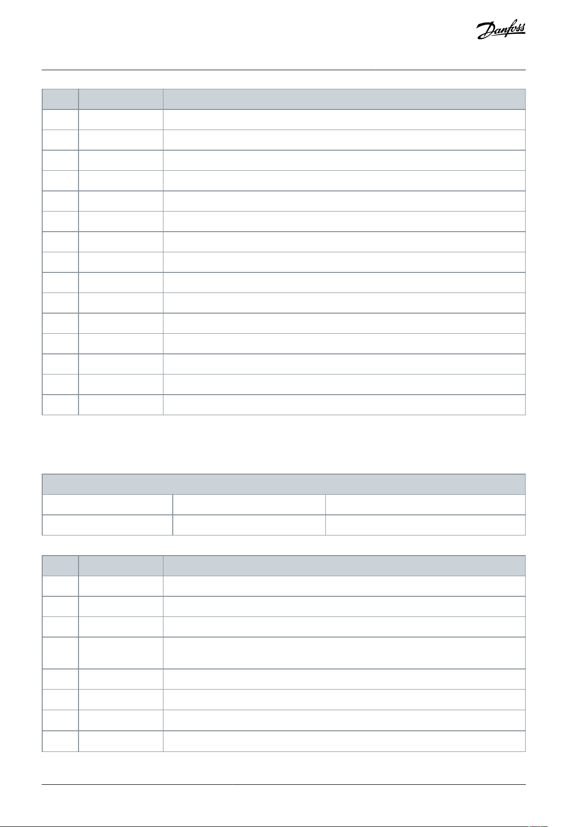
Option
Name
Description
[34]
Digital input DI19
Use the value of DI19 in the logic rule (high=true).
[35]
Digital input DI27
Use the value of DI27 in the logic rule (high=true).
[36]
Digital input DI29
Use the value of DI29 in the logic rule (high=true).
[39]
Start command
The event is true if the drive is started (either via digital input, fieldbus, or other).
[40]
Drive stopped
The event is true if the drive is stopped or coasted (either via digital input, fieldbus, or other).
[42]
Auto reset trip
The event is true if the drive is tripped (but not trip locked) and an automatic reset is issued.
[50]
Comparator 4
Use the result of comparator 4 in the logic rule.
[51]
Comparator 5
Use the result of comparator 5 in the logic rule.
[60]
Logic rule 4
Use the result of logic rule 4 in the logic rule.
[61]
Logic rule 5
Use the result of logic rule 5 in the logic rule.
[70]
SL timeout 3
Use the result of timer 3 in the logic rule.
[71]
SL timeout 4
Use the result of timer 4 in the logic rule.
[72]
SL timeout 5
Use the result of timer 5 in the logic rule.
[73]
SL timeout 6
Use the result of timer 6 in the logic rule.
[74]
SL timeout 7
Use the result of timer 7 in the logic rule.
13-51 SL Controller Event
Default value: False
Parameter type: Option
Setup: 1 setup
Conversion index: –
Data type: Uint8 [20]
Change during operation: False
Option
Name
Description
[0]*
False
Enters the fixed value of FALSE in the logic rule.
[1]
True
Enters the fixed value of TRUE in the logic rule.
[2]
Running
The compressor runs.
[3]
In range
The compressor runs within the programed current ranges (parameter 4-50 Warning Current Low
and parameter 4-51 Warning Current High).
[4]
On reference
The compressor runs at reference speed.
[7]
Out of current range
The compressor current is outside the range set in parameter 4-18 Current Limit.
[8]
Below I
low
The compressor current is lower than set in parameter 4-50 Warning Current Low.
[9]
Above I
high
The compressor current is higher than set in parameter 4-51 Warning Current High.
VLT® Compressor Drive CDS 803
Programming Guide
Parameter Descriptions and
Functions
5.2.9.5 Parameter Group 13-5* States
Parameter 13-51 SL Controller Event
Table 116: Parameter 13-51 SL Controller Event
Select the boolean input (TRUE or FALSE) to define the smart logic controller even.
AU356039245821 en-000201 / 130R059780 | Danfoss A/S © 2021.07
Page 81

Option
Name
Description
[16]
Thermal warning
The thermal warning turns on when the temperature exceeds the limit in the compressor, the
drive, or the thermistor.
[17]
Mains out of range
[18]
Reversing
The drive runs in reverse direction.
[19]
Warning
A warning is present.
[20]
Alarm (trip)
An alarm is present.
[21]
Alarm (trip lock)
A trip lock alarm is present.
[22]
Comparator 0
Use the result of comparator 0 in the logic rule.
[23]
Comparator 1
Use the result of comparator 1 in the logic rule.
[24]
Comparator 2
Use the result of comparator 2 in the logic rule.
[25]
Comparator 3
Use the result of comparator 3 in the logic rule.
[26]
Logic rule 0
Use the result of the logic rule 0 in the logic rule.
[27]
Logic rule 1
Use the result of the logic rule 1 in the logic rule.
[28]
Logic rule 2
Use the result of the logic rule 2 in the logic rule.
[29]
Logic rule 3
Use the result of the logic rule 3 in the logic rule.
[30]
SL timeout 0
Use the result of timer 0 in the logic rule.
[31]
SL timeout 1
Use the result of timer 1 in the logic rule.
[32]
SL timeout 2
Use the result of timer 2 in the logic rule.
[33]
Digital input DI18
Use the value of DI18 in the logic rule (high=true).
[34]
Digital input DI19
Use the value of DI19 in the logic rule (high=true).
[35]
Digital input DI27
Use the value of DI27 in the logic rule (high=true).
[36]
Digital input DI29
Use the value of DI29 in the logic rule (high=true).
[39]
Start command
The event is true if the drive is started (either via digital input, fieldbus, or other).
[40]
Drive stopped
The event is true if the drive is stopped or coasted (either via digital input, fieldbus, or other).
[42]
Auto reset trip
The event is true if the drive is tripped (but not trip locked) and an automatic reset is issued.
[50]
Comparator 4
Use the result of comparator 4 in the logic rule.
[51]
Comparator 5
Use the result of comparator 5 in the logic rule.
[60]
Logic rule 4
Use the result of logic rule 4 in the logic rule.
[61]
Logic rule 5
Use the result of logic rule 5 in the logic rule.
[70]
SL timeout 3
Use the result of timer 3 in the logic rule.
[71]
SL timeout 4
Use the result of timer 4 in the logic rule.
VLT® Compressor Drive CDS 803
Programming Guide
Parameter Descriptions and
Functions
AU356039245821 en-000201 / 130R0597 | 81Danfoss A/S © 2021.07
Page 82

Option
Name
Description
[72]
SL timeout 5
Use the result of timer 5 in the logic rule.
[73]
SL timeout 6
Use the result of timer 6 in the logic rule.
[74]
SL timeout 7
Use the result of timer 7 in the logic rule.
13-52 SL Controller Action
Default value: Disabled
Parameter type: Option
Setup: 1 setup
Conversion index: –
Data type: Uint8 [20]
Change during operation: False
Option
Name
Description
[0]*
Disabled
[1]
No action
[2]
Select setup 1
Changes the active setup to 1.
[3]
Select setup 2
Changes the active setup to 2.
[10]
Select preset ref 0
Selects preset reference 0.
[11]
Select preset ref 1
Selects preset reference 1.
[12]
Select preset ref 2
Selects preset reference 2.
[13]
Select preset ref 3
Selects preset reference 3.
[14]
Select preset ref 4
Selects preset reference 4.
[15]
Select preset ref 5
Selects preset reference 5.
[16]
Select preset ref 6
Selects preset reference 6.
[17]
Select preset ref 7
Select preset ref 7. If the active preset reference is changed, it merges with other preset reference commands coming from either the digital inputs or via a fieldbus.
[18]
Select ramp 1
Selects ramp 1.
[19]
Select ramp 2
Selects ramp 2.
[22]
Run
Issues a start command to the drive.
[23]
Run reverse
Issues a start reverse command to the drive.
[24]
Stop
Issues a stop command to the drive.
[25]
Qstop
Issues a quick stop command to the drive.
[26]
DC brake
Issues a DC stop command to the drive.
[27]
Coast
The drive coasts immediately. All stop commands, including the coast command, stop the SLC.
[28]
Freeze output
Freezes the output frequency fo the drive.
VLT® Compressor Drive CDS 803
Parameter Descriptions and
Programming Guide
Parameter 13-52 SL Controller Action
Table 117: Parameter 13-52 SL Controller Action
Select the action corresponding to the SLC event. Actions are executed when the corresponding event (defined in parameter 13-51
SL Controller Event) is evaluated as true.
Functions
AU356039245821 en-000201 / 130R059782 | Danfoss A/S © 2021.07
Page 83

Option
Name
Description
[29]
Start timer 0
Starts timer 0, see parameter 13-20 SL Controller Timer for further descriptions.
[30]
Start timer 1
Starts timer 1, see parameter 13-20 SL Controller Timer for further descriptions.
[31]
Start timer 2
Starts timer 2, see parameter 13-20 SL Controller Timer for further descriptions.
[32]
Set digital out A low
Any output with digital output 1 selected is low (off).
[33]
Set digital out B low
Any output with digital output 2 selected is low (off).
[34]
Set digital out C low
Any output with digital output 3 selected is low (off).
[35]
Set digital out D low
Any output with digital output 4 selected is low (off).
[38]
Set digital out A high
Any output with digital output 1 selected is high (closed).
[39]
Set digital out B high
Any output with digital output 2 selected is high (closed).
[40]
Set digital out C high
Any output with digital output 3 selected is high (closed).
[41]
Set digital out D high
Any output with digital output 4 selected is high (closed).
[60]
Reset counter A
Resets counter A to 0.
[61]
Reset counter B
Resets counter B to 0.
[70]
Start timer 3
Starts timer 3.
[71]
Start timer 4
Starts timer 4.
[72]
Start timer 5
Starts timer 5.
[73]
Start timer 6
Starts timer 6.
[74]
Start timer 7
Starts timer 7.
[100]
ResetAlarm
14-01 Switching Frequency
Default value: ExpressionLimit
Parameter type: Option
Setup: 2 setups
Conversion index: –
Data type: Uint8
Change during operation: False
VLT® Compressor Drive CDS 803
Programming Guide
Parameter Descriptions and
Functions
5.2.10 Parameter Group 14-** Special Functions
5.2.10.1 Parameter Group 14-0* Inverter Switching
Parameter 14-01 Switching Frequency
Table 118: Parameter 14-01 Switching Frequency
Select the inverter switching frequency. Changing the switching frequency can help to reduce acoustic noise from the compressor.
N O T I C E
The output frequency value of the drive must never exceed 1/10 of the switching frequency. When the compressor runs, adjust
the switching frequency in this parameter until the compressor is as noiseless as possible.
N O T I C E
High switching frequencies heat the drive and may reduce its lifetime.
AU356039245821 en-000201 / 130R0597 | 83Danfoss A/S © 2021.07
Page 84

Option
Name
Description
[0]
Ran3
3 kHz true random PWM (white noise modulation).
[1]
Ran5
5 kHz true random PWM (white noise modulation).
[2]
2.0 kHz
[3]
3.0 kHz
[4]
4.0 kHz
[5]
5.0 kHz
[6]
6.0 kHz
[7]
8.0 kHz
[8]
10.0 kHz
[9]
12.0 kHz
[10]
16.0 kHz
14-03 Overmodulation
Default value: On
Parameter type: Option
Setup: 2 setups
Conversion index: –
Data type: Uint8
Change during operation: False
Option
Name
Description
[0]
Off
Selects no overmodulation of the output voltage to avoid torque ripple on the compressor shaft.
[1]*OnThe overmodulation function generates an extra voltage of up to 8% of U
max
output voltage without overmodulation, which results in an extra torque of 10–12% in the middle of the oversynchronous range (from =
% at nominal speed rising to approximately 12% at double nominal speed).
[2]
2.0 kHz
[3]
3.0 kHz
[4]
4.0 kHz
[5]
5.0 kHz
[6]
6.0 kHz
[7]
8.0 kHz
[8]
10.0 kHz
[9]
12.0 kHz
[10]
16.0 kHz
VLT® Compressor Drive CDS 803
Programming Guide
Parameter Descriptions and
Functions
Parameter 14-03 Overmodulation
Table 119: Parameter 14-03 Overmodulation
5.2.10.2 Parameter Group 14-1* Mains On/Off
Parameters for configuring mains failure monitoring and handling.
AU356039245821 en-000201 / 130R059784 | Danfoss A/S © 2021.07
Page 85

14-11 Mains Fault Voltage Level
Default value: ExpressionLimit
Parameter type: Range [100 – 800 V]
Setup: 2 setups
Conversion index: 0
Data type: Uint16
Change during operation: False
14-03 Overmodulation
Default value: Warning
Parameter type: Option
Setup: 1 setup
Conversion index: –
Data type: Uint8
Change during operation: False
Option
Name
Description
[0]
Trip
Trips the drive.
[1]*
Warning
Issues a warning.
[2]
Disabled
No action.
N O T I C E
Disabling this parameter may lead to reduced lifetime.
[3]
Derate
Derates the load by mains imbalance.
14-22 Operation Mode
Default value: Normal operation
Parameter type: Option
Setup: 1 setup
Conversion index: –
Data type: Uint8
Change during operation: False
Option
Name
Description
[0]*
Normal operation
Select this option for normal operation of the drive with the compressor in the selected application.
[2]
Initialisation
To reset all parameter values to default settings, select this option. Parameter 15-03 Power Up's, pa-
rameter 15-04 Over Temp's, and parameter 15-05 Over Volt's are not reset with this option. The drive
VLT® Compressor Drive CDS 803
Parameter Descriptions and
Programming Guide
Parameter 14-11 Mains Fault Voltage Level
Table 120: Parameter 14-11 Mains Fault Voltage Level
This parameter defines the threshold voltage at which the selected function in parameter 14.10 Mains Failure should be activated.
The detection level is at a factor sqrt2 of the value in this parameter.
Parameter 14-12 Response to Mains Imbalance
Table 121: Parameter 14-03 Overmodulation
Functions
Operation under severe mains imbalance conditions reduces the lifetime of the compressor. If the compressor is operated continuously near nominal load, conditions are considered severe. When a severe mains imbalance is detected, select 1 of the available
functions.
5.2.10.3 Parameter Group 14-2* Trip Reset
Parameter 14-22 Operation Mode
Table 122: Parameter 14-22 Operation Mode
To reset all parameter values to default, select [2] Initialisation.
AU356039245821 en-000201 / 130R0597 | 85Danfoss A/S © 2021.07
Page 86

Option
Name
Description
resets during the next power-up. Parameter 14-22 Operation Mode also reverts to the default setting
[2] Initialisation.
14-24 Trip Delay at Current Limit
Default value: 60 s
Parameter type: Range [0 – 60 s]
Setup: 1 setup
Conversion index: 0
Data type: Uint8
Change during operation: False
14-27 Action at Inverter Fault
Default value: Warning
Parameter type: Option
Setup: 2 setups
Conversion index: –
Data type: Uint8
Change during operation: False
Option
Name
Description
[0]
Trip
[1]*
Warning
14-30 Current Lim Ctrl, Proportional Gain
Default value: 100%
Parameter type: Range [0 – 500%]
Setup: 2 setups
Conversion index: 0
Data type: Uint16
Change during operation: False
14-31 Current Lim Ctrl, Integration Time
Default value: ExpressionLimit
Parameter type: Range [0.002 – 2 s]
Setup: 2 setups
Conversion index: -3
Data type: Uint16
Change during operation: False
VLT® Compressor Drive CDS 803
Parameter Descriptions and
Programming Guide
Parameter 14-24 Trip Delay at Current Limit
Table 123: Parameter 14-24 Trip Delay at Current Limit
Enter the current limit trip delay in s. When the output reaches the current limit, a warning is triggered. When the current limit
warning has been continuously present for the period specified in this parameter, the drive trips. To run continuously in current
limit without tripping, set this parameter to 60 s. Thermal monitoring of the drive remains active.
Parameter 14-27 Action at Inverter Fault
Table 124: Parameter 14-27 Action at Inverter Fault
Functions
Select how the drive acts if overvoltage, overcurrent, short circuit, or grounding errors occur.
5.2.10.4 Parameter Group 14-3* Current Limit Control
Parameters for configuring the current limit controller, which is activated when the compressor current exceeds the preset current
limits (see parameter 4-18 Current Limit). These parameters are used to reduce torque as quickly as possible without losing control of
the compressor.
Parameter 14-30 Current Lim Ctrl, Proportional Gain
Table 125: Parameter 14-30 Current Lim Ctrl, Proportional Gain
Enter the proportional gain value for the current limit controller. A higher value makes the controller react faster. Excessive value
setting leads to controller instability.
Parameter 14-31 Current Lim Ctrl, Integration Time
Table 126: Parameter 14-31 Current Lim Ctrl, Integration Time
Enter the current limit control integration time. Setting the time to a lower value makes it react faster. A setting too low leads to
control instability.
AU356039245821 en-000201 / 130R059786 | Danfoss A/S © 2021.07
Page 87

14-32 Current Lim Ctrl, Filter Time
Default value: ExpressionLimit
Parameter type: Range [1 – 100 ms]
Setup: 2 setups
Conversion index: -4
Data type: Uint16
Change during operation: False
14-55 Output Filter
Default value: No filter
Parameter type: Option
Setup: 1 setup
Conversion index: –
Data type: Uint8
Change during operation: False
Option
Name
Description
[0]*
No filter
[1]
Sine-wave filter
[3]
Sine-wave filter with feedback
14-61 Function at Inverter Overload
Default value: Trip
Parameter type: Option
Setup: 2 setups
Conversion index: –
Data type: Uint8
Change during operation: False
Option
Name
Description
[0]*
Trip
[1]
Derate
14-61 Function at Inverter Overload
Default value: 2.0 kHz
Parameter type: Option
Setup: 1 setup
Conversion index: –
Data type: Uint8
Change during operation: False
VLT® Compressor Drive CDS 803
Programming Guide
Parameter 14-32 Current Lim Ctrl, Filter Time
Table 127: Parameter 14-32 Current Lim Ctrl, Filter Time
Set a time constant for the current limit controller low-pass filter.
5.2.10.5 Parameter Group 14-5* Environment
These parameters help the drive to operate under special environmental conditions.
Parameter 14-55 Output Filter
Table 128: Parameter 14-55 Output Filter
Parameter Descriptions and
Functions
5.2.10.6 Parameter Group 14-6* Auto Derate
Paramter group for configuring automatic derating based on the output frequency of the drive.
Parameter 14-61 Function at Inverter Load
Table 129: Parameter 14-61 Function at Inverter Overload
When the drive issues an inverter overload warning, select whether to continue, and probably trip the drive, or to derate the output
current.
Parameter 14-63 Min Switch Frequency
Table 130: Parameter 14-61 Function at Inverter Overload
Set the minimum switching frequency allowed by the output filter.
AU356039245821 en-000201 / 130R0597 | 87Danfoss A/S © 2021.07
Page 88

Option
Name
Description
[0]*
2.0 kHz
[3]
3.0 kHz
[4]
4.0 kHz
[5]
5.0 kHz
[6]
6.0 kHz
[7]
8.0 kHz
[8]
10.0 kHz
[9]
12.0 kHz
[10]
16.0 kHz
15-00 Operating Hours
Default value: 0 h
Parameter type: Range [0 – 0x7FFFFFFF h]
Setup: 1 setup
Conversion index: 74
Data type: Uint32
Change during operation: False
15-01 Running Hours
Default value: 0 h
Parameter type: Range [0 – 0x7FFFFFFF h]
Setup: 1 setup
Conversion index: 74
Data type: Uint32
Change during operation: False
15-03 Power Up's
Default value: 0
Parameter type: Range [0 – 2147483647]
Setup: 1 setup
Conversion index: 0
Data type: Uint32
Change during operation: False
VLT® Compressor Drive CDS 803
Parameter Descriptions and
Programming Guide
5.2.11 Parameter Group 15-** Drive Information
This parameter group contains drive information, such as operating data, hardware configuration, and software versions.
Functions
5.2.11.1 Parameter Group 15-0* Operating Data
Parameter 15-00 Operating Hours
Table 131: Parameter 15-00 Operating Hours
View how many hours the drive has run. The value is saved when the drive is turned off.
Parameter 15-01 Running Hours
Table 132: Parameter 15-01 Running Hours
View how many hours the compressor has run. Reset the counter in parameter 15-07 Reset Running Hours Counter. The value is saved
when the drive is turned off.
Parameter 15-03 Power Up's
Table 133: Parameter 15-03 Power Up's
View the number of times the drive has been powered up.
AU356039245821 en-000201 / 130R059788 | Danfoss A/S © 2021.07
Page 89

15-04 Over Temp's
Default value: 0
Parameter type: Range [0 – 65535]
Setup: 1 setup
Conversion index: 0
Data type: Uint16
Change during operation: False
15-05 Over Volt's
Default value: 0
Parameter type: Range [0 – 65535]
Setup: 1 setup
Conversion index: 0
Data type: Uint16
Change during operation: False
15-06 Reset kWh Counter
Default value: Do not reset
Parameter type: Option
Setup: 1 setup
Conversion index: –
Data type: Uint8
Change during operation: False
Option
Name
Description
[0]*
Do not reset
[1]
Reset counter
To reset the kWh counter to 0, select [1] Reset and press [OK].
15-07 Reset Running Hours Counter
Default value: Do not reset
Parameter type: Option
Setup: 1 setup
Conversion index: –
Data type: Uint8
Change during operation: False
Option
Name
Description
[0]*
Do not reset
[1]
Reset counter
To reset the running hours counter, select [1] Reset and press [OK].
15-08 Number of Starts
Default value: 0
Parameter type: Range [0 – 2147483647]
Setup: 2 setups
Conversion index: 0
Data type: Uint32
Change during operation: False
VLT® Compressor Drive CDS 803
Programming Guide
Parameter 15-04 Over Temp's
Table 134: Parameter 15-04 Over Temp's
View the number of drive temperature faults that have occurred.
Parameter 15-05 Over Volt's
Table 135: Parameter 15-05 Over Volt's
View the number of drive overvoltages that have occurred.
Parameter 15-06 Reset kWh Counter
Table 136: Parameter 15-06 Reset kWh Counter
Parameter Descriptions and
Functions
Parameter 15-07 Reset Running Hours Counter
Table 137: Parameter 15-07 Reset Running Hours Counter
Parameter 15-08 Number of Starts
Table 138: Parameter 15-08 Number of Starts
States the number of starts executed on the drive. The counter can be reset in parameter 15-07 Reset Running Hours Counter. The
value is saved when the drive is turned off.
AU356039245821 en-000201 / 130R0597 | 89Danfoss A/S © 2021.07
Page 90

15-09 Number of Auto Resets
Default value: 0
Parameter type: Range [0 – 2147483647]
Setup: 2 setups
Conversion index: 0
Data type: Uint32
Change during operation: False
15-30 Alarm Log: Error Code
Default value: 0
Parameter type: Range [0 – 255]
Setup: 1 setup
Conversion index: 0
Data type: Uint8 [10]
Change during operation: False
15-31 InternalFaultReason
Default value: 0
Parameter type: Range [-32767 – 32767]
Setup: 1 setup
Conversion index: 0
Data type: Uint16
Change during operation: False
15-40 FC Type
Default value: 0
Parameter type: Range [0 – 6]
Setup: 1 setup
Conversion index: 0
Data type: VisibleString of length 6
Change during operation: False
15-41 Power Section
Default value: 0
Parameter type: Range [0 – 20]
Setup: 1 setup
Conversion index: 0
Data type: VisibleString of length 20
Change during operation: False
VLT® Compressor Drive CDS 803
Parameter Descriptions and
Programming Guide
Parameter 15-09 Number of Auto Resets
Table 139: Parameter 15-09 Number of Auto Resets
States the number of auto resets executed by the drive.
Functions
5.2.11.2 Parameter Group 15-3* Alarm Log
Parameters in this group are array parameters, where up to 10 faults log can be viewed. [0] is the most recent logged data, and [9]
the oldest. Fault codes, values, and time stamp can be viewed for all logged data.
Parameter 15-30 Alarm Log: Error Code
Table 140: Parameter 15-30 Alarm Log: Error Code
View the fault code and look up its meaning in 6 Troubleshooting.
Parameter 15-31 InternalFaultReason
Table 141: Parameter 15-31 InternalFaultReason
View a description of the error. This parameter is used with alarm 38, Internal Fault.
5.2.11.3 Parameter Group 15-4* Drive Identification
Parameters containing read-only information about the hardware and software configuration of the drive.
Parameter 15-40 FC Type
Table 142: Parameter 15-40 FC Type
View the FC type code. The readout is identical to the drive series power field of the type code definition, characters 1–6.
Parameter 15-41 Power Section
Table 143: Parameter 15-41 Power Section
View the FC type code. The readout is identical to the drive series power field of the type code definition, characters 7–10.
AU356039245821 en-000201 / 130R059790 | Danfoss A/S © 2021.07
Page 91

15-42 Voltage
Default value: 0
Parameter type: Range [0 – 20]
Setup: 1 setup
Conversion index: 0
Data type: VisibleString of length 20
Change during operation: False
15-43 Software Version
Default value: 0
Parameter type: Range [0 – 0]
Setup: 1 setup
Conversion index: 0
Data type: VisibleString of length 20
Change during operation: False
15-44 Ordered TypeCode
Default value: 0
Parameter type: Range [0 – 40]
Setup: 1 setup
Conversion index: 0
Data type: VisibleString of length 40
Change during operation: False
15-45 Actual Typecode String
Default value: 0
Parameter type: Range [0 – 40]
Setup: 2 setups
Conversion index: 0
Data type: VisibleString of length 40
Change during operation: False
15-46 Drive Ordering No
Default value: 0
Parameter type: Range [0 – 8]
Setup: 1 setup
Conversion index: 0
Data type: VisibleString of length 8
Change during operation: False
15-48 LCP ID No
Default value: 0
Parameter type: Range [0 – 0]
Setup: 1 setup
Conversion index: 0
Data type: VisibleString of length 21
Change during operation: False
VLT® Compressor Drive CDS 803
Parameter Descriptions and
Programming Guide
Parameter 15-42 Voltage
Table 144: Parameter 15-42 Voltage
View the FC type code. The readout is identical to the drive series power field of the type code definition, characters 11–12.
Parameter 15-43 Software Version
Table 145: Parameter 15-43 Software Version
View the software version of the drive.
Parameter 15-44 Ordered TypeCode
Functions
Table 146: Parameter 15-44 Ordered TypeCode
View the type code string used for reordering the drive in its original configuration.
Parameter 15-45 Actual Typecode String
Table 147: Parameter 15-45 Actual Typecode String
View the actual type code string.
Parameter 15-46 Drive Ordering No
Table 148: Parameter 15-46 Drive Ordering No
View the 8-digit ordering number for reordering the drive in its original configuration.
Parameter 15-48 LCP ID No
Table 149: Parameter 15-48 LCP ID No
View the LCP ID number.
AU356039245821 en-000201 / 130R0597 | 91Danfoss A/S © 2021.07
Page 92

15-49 SW ID Control Card
Default value: 0
Parameter type: Range [0 – 0]
Setup: 1 setup
Conversion index: 0
Data type: VisibleString of length 21
Change during operation: False
15-50 SW ID Power Card
Default value: 0
Parameter type: Range [0 – 0]
Setup: 1 setup
Conversion index: 0
Data type: VisibleString of length 21
Change during operation: False
15-51 Drive Serial Number
Default value: 0
Parameter type: Range [0 – 10]
Setup: 1 setup
Conversion index: 0
Data type: VisibleString of length 10
Change during operation: False
15-53 Power Card Serial Number
Default value: 0
Parameter type: Range [0 – 0]
Setup: 1 setup
Conversion index: 0
Data type: VisibleString of length 10
Change during operation: False
15-59 Filename
Default value: 0
Parameter type: Range [0 – 16]
Setup: 1 setup
Conversion index: 0
Data type: VisibleString of length 16 [2]
Change during operation: False
VLT® Compressor Drive CDS 803
Programming Guide
SW ID Control Card
Table 150: Parameter 15-49 SW ID Control Card
View the control card software version number.
Parameter 15-50 SW ID Power Card
Table 151: Parameter 15-50 SW ID Power Card
View the power card software version number.
Parameter 15-51 Drive Serial Number
Parameter Descriptions and
Functions
Table 152: Parameter 15-51 Drive Serial Number
View the serial number of the drive.
Parameter 15-53 Power Card Serial Number
Table 153: Parameter 15-53 Power Card Serial Number
View the serial number of the power card.
Parameter 15-59 Filename
Table 154: Parameter 15-59 Filename
View the current CSIV file name.
AU356039245821 en-000201 / 130R059792 | Danfoss A/S © 2021.07
Page 93

16-00 Control Word
Default value: 0
Parameter type: Range [0 – 65535]
Setup: 1 setup
Conversion index: 0
Data type: Uint16
Change during operation: False
Bit
Bit=0
Bit=1
00
Preset reference option lsb
–
01
Preset reference option 2nd bit of preset references
–
02
DC brake
Ramp
03
Coasting
Enable
04
Quick stop
Ramp
05
Freeze output
Ramp
06
Ramp stop
Start07No function
Reset
08
No function
Jog09Ramp 1
Ramp 2
10
Data not valid
Valid11Relay_A not active
Relay_A active
12
Relay_B not active
Relay_B active
13
Choice of set-up lsb
–14No function
No function
15
No function
Reversing
16-01 Reference [Unit]
Default value: 0 ReferenceFeedback
Parameter type: Range [-4999 – 4999 ReferenceFeedback]
Setup: 1 setup
Conversion index: -3
Data type: Int32
Change during operation: False
VLT® Compressor Drive CDS 803
Programming Guide
5.2.12 Parameter Group 16-** Data Readouts
5.2.12.1 Parameter Group 16-0* General Status
Parameter 16-00 Control Word
Table 155: Parameter 16-00 Control Word
View the control word sent from the drive via the serial communication port in hex code.
Table 156: Control Bit Descriptions
Parameter Descriptions and
Functions
Parameter 16-01 Reference [Unit]
Table 157: Parameter 16-01 Reference [Unit]
View the preset reference value applied on impulse or analog basis in the unit resulting from the configuration selected in parameter 1-00 Configuration Mode.
AU356039245821 en-000201 / 130R0597 | 93Danfoss A/S © 2021.07
Page 94

16-02 Reference [%]
Default value: 0%
Parameter type: Range [-200 – 200%]
Setup: 1 setup
Conversion index: -1
Data type: Int16
Change during operation: False
16-03 Status Word
Default value: 0
Parameter type: Range [0 – 65535]
Setup: 1 setup
Conversion index: 0
Data type: Uint16
Change during operation: False
Bit
Bit=0
Bit=1
00
Control not ready
Ready
01
VLT not ready
Ready
02
Coasting
Enable
03
No fault
Trip04No warning
Warning
05
Reversed
–06No trip lock
Trip lock
07
No warning
Warning
08
Speed≠ref.
Speed=ref.
09
Local control
Bus control
10
Out of range
Frequency OK
11
Not running
Running
12
No function
No function
13
Voltage OK
Above limit
14
Current OK
Above limit
15
Temperature OK
Above limit
VLT® Compressor Drive CDS 803
Parameter Descriptions and
Programming Guide
Parameter 16-02 Reference [%]
Table 158: Parameter 16-02 Reference [%]
View the total reference. The total reference is the sum of digital, analog, preset, bus, and freeze references.
Parameter 16-03 Status Word
Table 159: Parameter 16-03 Status Word
View the status word sent from the drive via the serial communication port in hex code.
Functions
Table 160: Status Bit Descriptions
AU356039245821 en-000201 / 130R059794 | Danfoss A/S © 2021.07
Page 95

16-05 Main Actual Value [%
Default value: 0%
Parameter type: Range [-200 – 200%]
Setup: 1 setup
Conversion index: -2
Data type: Int16
Change during operation: False
16-09 Main Actual Value [%]
Default value: 0 CustomReadout
Parameter type: Range [0 – 9999 CustomReadout]
Setup: 1 setup
Conversion index: -2
Data type: Int32
Change during operation: False
16-10 Power [kW]
Default value: 0 kW
Parameter type: Range [0 – 1000 kW]
Setup: 1 setup
Conversion index: -3
Data type: Uint32
Change during operation: False
16-11 Power [hp]
Default value: 0 hp
Parameter type: Range [0 – 1000 hp]
Setup: 1 setup
Conversion index: -3
Data type: Uint32
Change during operation: False
16-12 Motor Voltage
Default value: 0 V
Parameter type: Range [0 – 65535 V]
Setup: 1 setup
Conversion index: -1
Data type: Uint32
Change during operation: False
VLT® Compressor Drive CDS 803
Parameter Descriptions and
Programming Guide
Parameter 16-05 Main Actual Value [%]
Table 161: Parameter 16-05 Main Actual Value [%]
View the 2-byte word sent with the status word to the bus master reporting the main actual value.
Parameter 16-09 Custom Readout
Table 162: Parameter 16-09 Custom Readout
View the user-defined readouts as defined in parameter 0-30 Custom Readout Unit, parameter 0-31 Custom Readout Min Value, and
parameter 0-32 Custom Readout Max Value.
Functions
5.2.12.2 Parameter Group 16-1* Motor Status
Parameter 16-10 Power [kW]
Table 163: Parameter 16-10 Power [kW]
Shows the actual compressor power in kW. The value is calculated based on the actual compressor voltage and compressor current.
Parameter 16-11 Power [hp]
Table 164: Parameter 16-11 Power [hp]
Shows the actual compressor power in hp. The value is calculated based on the actual compressor voltage and compressor current.
Parameter 16-12 Motor Voltage
Table 165: Parameter 16-12 Motor Voltage
View the compressor voltage, a calculated value used for controlling the compressor.
AU356039245821 en-000201 / 130R0597 | 95Danfoss A/S © 2021.07
Page 96

16-13 Frequency
Default value: 0 Hz
Parameter type: Range [0 – 6553.5 Hz]
Setup: 1 setup
Conversion index: -1
Data type: Uint32
Change during operation: False
16-14 Motor Current
Default value: 0 A
Parameter type: Range [0 – 655.35 A]
Setup: 1 setup
Conversion index: -2
Data type: Uint16
Change during operation: False
16-15 Frequency
Default value: 0%
Parameter type: Range [0 – 6553.5%]
Setup: 1 setup
Conversion index: -1
Data type: Uint16
Change during operation: False
16-16 Torque [Nm]
Default value: 0 Nm
Parameter type: Range [-30000 – 30000 Nm]
Setup: 2 setups
Conversion index: -1
Data type: Int32
Change during operation: False
16-17 Speed [RPM]
Default value: 0 RPM
Parameter type: Range [-30000 – 30000 RPM]
Setup: 2 setups
Conversion index: -1
Data type: Int32
Change during operation: False
VLT® Compressor Drive CDS 803
Programming Guide
Parameter 16-13 Frequency
Table 166: Parameter 16-13 Frequency
View the compressor frequency, without resonance damping.
Parameter 16-14 Motor Current
Table 167: Parameter 16-14 Motor Current
Parameter Descriptions and
Functions
View the compressor current measured as an average value, I
RMS
.
Parameter 16-15 Frequency [%]
Table 168: Parameter 16-15 Frequency [%]
View a 2-byte word reporting the actual compressor frequency (without resonance damping) as a percentage (scale 0000–
4000 hex) of parameter 4-19 Max Output Frequency.
Parameter 16-16 Torque [Nm]
Table 169: Parameter 16-16 Torque [Nm]
View the torque value with sign, applied to the motor shaft. Linearity is not exact between 160% motor current and torque in relation to the rated torque. Some motors supply more than 160% torque. Therefore, the minimum value and the maximum value depend on the maximum motor current and the motor used. The value is filtered, and thus approximately 30 ms may pass from when
an input changes value to when the data readout values change.
Parameter 16-17 Speed [RPM]
Table 170: Parameter 16-17 Speed [RPM]
View the actual motor RPM. The motor RPM is estimated in open-loop process or closed-loop process control modes and the motor
RPM is measured in speed closed-loop mode.
AU356039245821 en-000201 / 130R059796 | Danfoss A/S © 2021.07
Page 97

16-18 Motor Thermal
Default value: 0%
Parameter type: Range [0 - 100%]
Setup: 1 setup
Conversion index: 0
Data type: Uint8
Change during operation: False
16-22 Torque [%]
Default value: 0%
Parameter type: Range [-200 - 200%]
Setup: 2 setups
Conversion index: 0
Data type: Uint16
Change during operation: False
16-30 DC Link Voltage
Default value: 0 V
Parameter type: Range [0 - 65535 V]
Setup: 1 setup
Conversion index: 0
Data type: Uint32
Change during operation: False
16-34 Heatsink Temp.
Default value: 0 °C
Parameter type: Range [-128 - 127 °C]
Setup: 1 setup
Conversion index: 100
Data type: Int8
Change during operation: False
16-35 Inverter Thermal
Default value: 0%
Parameter type: Range [0 - 255%]
Setup: 1 setup
Conversion index: 0
Data type: Uint8
Change during operation: False
VLT® Compressor Drive CDS 803
Parameter Descriptions and
Programming Guide
Parameter 16-18 Motor Thermal
Table 171: Parameter 16-18 Motor Thermal
View the calculated compressor motor temperature in percentage of allowed maximum. At 100%, a trip occurs, if selected in parameter 1-90 Motor Thermal Protection. The basis for the calculation is the ETR function selected in parameter 1-90 Motor Thermal Protection.
Parameter 16-22 Torque [%]
Table 172: Parameter 16-22 Torque [%]
Functions
This is a readout parameter only. Shows the actual torque yielded in percentage of the rated torque, based on the setting of the
motor size, and rated speed in parameter 1-20 Motor Power or parameter 1-21 Motor Power [HP] and parameter 1-25 Motor Nominal.
5.2.12.3 Parameter Group 16-3* Drive Status
Parameter 16-30 DC Link Voltage
Table 173: Parameter 16-30 DC Link Voltage
Shows the actual DC-link voltage.
Parameter 16-34 Heatsink Temp.
Table 174: Parameter 16-34 Heatsink Temp.
View the heat sink temperature of the drive.
Parameter 16-35 Inverter Thermal
Table 175: Parameter 16-35 Inverter Thermal
View the percentage of thermal load on the drive. At 100%, a trip occurs.
AU356039245821 en-000201 / 130R0597 | 97Danfoss A/S © 2021.07
Page 98

16-36 Inv. Nom. Current
Default value: 0 A
Parameter type: Range [0 - 655.35 A]
Setup: 1 setup
Conversion index: -2
Data type: Uint16
Change during operation: False
16-37 Inv. Max. Current
Default value: 0 A
Parameter type: Range [0 - 655.35 A]
Setup: 1 setup
Conversion index: -2
Data type: Uint16
Change during operation: False
16-38 SL Controller State
Default value: 0
Parameter type: Range [0 - 20]
Setup: 1 setup
Conversion index: 0
Data type: Uint8
Change during operation: False
16-50 External Reference
Default value: 0%
Parameter type: Range [-200 - 200%]
Setup: 1 setup
Conversion index: -1
Data type: Int16
Change during operation: False
16-52 Feedback[Unit]
Default value: 0 ProcessCtrlUnit
Parameter type: Range [-4999 - 4999 ProcessCtrlUnit]
Setup: 1 setup
Conversion index: -3
Data type: Int32
Change during operation: False
VLT® Compressor Drive CDS 803
Programming Guide
Parameter 16-36 Inv. Nom. Current
Table 176: Parameter 16-36 Inv. Nom. Current
View the inverter nominal current. The data is used for compressor protection, and more.
Parameter 16-37 Inv. Max. Current
Table 177: Parameter 16-37 Inv. Max. Current
View the inverter maximum current. The data is used for calculation of drive protection, and more.
Parameter 16-38 SL Controller Site
Parameter Descriptions and
Functions
Table 178: Parameter 16-38 SL Controller State
View the actual state of the smart logic controller (SLC).
5.2.12.4 Parameter Group 16-5* Ref. & Feedb.
Parameter 16-50 External Reference
Table 179: Parameter 16-50 External Reference
View the total reference, the sum of digital, analog, preset, bus, and freeze references.
Parameter 16-52 Feedback[Unit]
Table 180: Parameter 16-52 Feedback[Unit]
View the feedback resulting from the selection of scaling in parameter 3-02 Minimum Reference and parameter 3-03 Maximum Reference.
AU356039245821 en-000201 / 130R059798 | Danfoss A/S © 2021.07
Page 99

16-54 Feedback 1 [Unit]
Default value: 0 ProcessCtrlUnit
Parameter type: Range [-999999.999 - 999999.999 ProcessCtrlUnit]
Setup: 2 setups
Conversion index: -3
Data type: Int32
Change during operation: False
16-55 Feedback 2 [Unit]
Default value: 0 ProcessCtrlUnit
Parameter type: Range [-999999.999 - 999999.999 ProcessCtrlUnit]
Setup: 2 setups
Conversion index: -3
Data type: Int32
Change during operation: False
16-60 Digital Input
Default value: 0
Parameter type: Range [0 - 4095]
Setup: 1 setup
Conversion index: 0
Data type: Uint16
Change during operation: False
Bit number
Description
0
Unused
1
Unused
2
Digital input terminal 29
3
Digital input terminal 27
4
Digital input terminal 19
5
Digital input terminal 18
6–15
Unused
16-61 Terminal 53 Setting
Default value: Current mode
Parameter type: Option
Setup: 1 setup
Conversion index: –
Data type: Uint8
Change during operation: False
VLT® Compressor Drive CDS 803
Parameter Descriptions and
Programming Guide
Parameter 16-54 Feedback 1 [Unit]
Table 181: Parameter 16-54 Feedback 1 [Unit]
View the feedback resulting from the selection of scaling in parameter 3-02 Minimum Reference and parameter 3-03 Maximum Reference.
Parameter 16-55 Feedback 2 [Unit]
Table 182: Parameter 16-55 Feedback 2 [Unit]
Functions
View the value of feedback 2, see parameter group 20-0* Feedback. The value is limited by settings in parameter 20-13 Minimum
Reference/ Feedb. and parameter 20-14 Maximum Reference/Feedb. Units as set in parameter 20-12 Reference/Feedback Unit.
5.2.12.5 Parameter Group 16-6* Inputs and Outputs
Parameter 16-60 Digital Input
Table 183: Parameter 16-60 Digital Input
View the actual state of the digital inputs 18, 19, 27, and 29.
Parameter 16-61 Terminal 53 Setting
Table 184: Parameter 16-61 Terminal 53 Setting
AU356039245821 en-000201 / 130R0597 | 99Danfoss A/S © 2021.07
Page 100

Option
Name
Description
[0]*
Current mode
[1]
Voltage mode
16-62 Analog Input 53
Default value: 1
Parameter type: Range [0 - 20]
Setup: 1 setup
Conversion index: -2
Data type: Uint16
Change during operation: False
16-63 Terminal 54 Setting
Default value: Current mode
Parameter type: Option
Setup: 1 setup
Conversion index: –
Data type: Uint8
Change during operation: False
Option
Name
Description
[0]*
Current mode
[1]
Voltage mode
16-64 Analog Input 54
Default value: 1
Parameter type: Range [0 - 20]
Setup: 1 setup
Conversion index: -2
Data type: Uint16
Change during operation: False
16-65 Analog Output 42 [mA]
Default value: 0 mA
Parameter type: Range [0 - 20 mA]
Setup: 1 setup
Conversion index: -2
Data type: Uint16
Change during operation: False
VLT® Compressor Drive CDS 803
Programming Guide
View the setting of terminal 53.
Parameter 16-62 Analog Input 53
Table 185: Parameter 16-62 Analog Input 53
View the actual input on analog input 53.
Parameter 16-63 Termianl 54 Setting
Table 186: Parameter 16-63 Terminal 54 Setting
Parameter Descriptions and
Functions
View the setting of terminal 54 (current or voltage).
Parameter 16-64 Analog Input 54
Table 187: Parameter 16-64 Analog Input 54
View the actual input on analog input 54.
Parameter 16-65 Analog Output 42 [mA]
Table 188: Parameter 16-65 Analog Output 42 [mA]
View the actual value at output 42 in mA. The value shown reflects the selection in parameter 6-90 Terminal 42 Mode and parameter
6-91 Terminal 42 Analog Output.
AU356039245821 en-000201 / 130R0597100 | Danfoss A/S © 2021.07
 Loading...