

Page 1
MAKING MODERN LIVING POSSIBLE
OOperating Instructions
VLTp Inverter Scroll CDS 801
Page 2

Page 3
Page 4

Page 5

Contents
Contents
VLT® Inverter Scroll CDS 801 Operating Instructions
1 General
1.1 Coverage
1.1.1 Disclaimer 4
1.1.2 Coverage 4
1.2 Safety Instructions
1.3 Approvals
1.4 General Warning
1.5 Disposal Instruction
1.6 Before Commencing Repair Work
1.7 ESD Precautions
1.8 Product Identification
1.9 Unpacking the Drive
1.10 Table of Abbreviations
2 Mechanical Installation
2.1 Dimensions and Weight
2.2 Installation Orientation and Clearances
2.2.1 Surface Mounting 9
4
4
4
4
5
5
5
5
5
5
6
7
7
9
2.2.2 Structural Mounting 11
2.3 Air Circulation/Cooling
2.4 Condensation and Dripping Water
2.5 Vibration and Mechanical Resonances
3 Electrical Installation
3.1 Electrical Connection in General
3.2 Tightening Torque
3.3 Cable Quality and Dimensioning
3.4 Fuses/Circuit Breakers
3.5 EMC Correct Installation
3.6 Electrical Connections
3.6.1 Routing of Motor and Supply Cable 15
3.6.2 Power Supply Connection (Mains) 16
3.6.3 Motor (Compressor) Connection 16
3.6.4 Sensor Connections 18
3.6.5 4-way Reversing Valve Connection 18
3.6.6 Condenser Fan Motor Control Connection (EXT_FAN) 18
12
12
12
13
13
13
13
13
14
15
3.6.7 EEV Controller (HP Mode) Connection (EEV_2) 18
3.6.8 Serial Communication Cable Connection 19
3.6.9 Connector Specification 20
3.6.10 Allocation of Connector Pins 21
MG10V402 - VLT® is a registered Danfoss trademark 1
Page 6

Contents
VLT® Inverter Scroll CDS 801 Operating Instructions
3.6.11 Overview Wiring Diagram 22
4 Serial Communication (Modbus RTU)
5 Commissioning
5.1 Initial Configuration of the Performer VSD sub-system
5.2 Drive Setup
5.2.1 Drive Parameters
(Modbus Registers, node 162) 27
5.2.2 Drive Parameters
(Modbus Registers, node 163) 28
5.3 Condenser Fan Speed Reference Output
5.4 Crankcase Heating
5.5 Ambient Temperature Source
5.6 Pressure sensor scaling
5.7 Normal Operation
6 Embedded Application Controller “Thermo Control”
6.1 Introduction
6.2 Applications
6.2.1 Generic AC 31
25
27
27
27
29
29
29
30
30
31
31
31
6.2.2 Generic AC/HP (Reversible) 32
6.2.3 Ground Source Heat Pump (Reversible) 33
6.3 Application Controller
6.3.1 Introduction 33
6.3.2 System Modes 33
6.3.2.1 Off 33
6.3.2.2 AC 33
6.3.2.3 HP 34
6.3.2.4 Defrost 34
6.3.3 Compressor Capacity Control 34
6.3.3.1 Single Loop Room Temperature Control 35
6.3.3.2 Open Loop/ External Speed Control 35
6.3.4 Condensing Pressure Control 36
6.3.4.1 AC Mode 36
6.3.4.2 HP Mode 38
6.3.4.3 Defrost Mode 39
6.3.5 Auxiliary Functions 39
33
6.3.5.1 Start-Up Sequence 39
6.3.5.2 Restart Timer 40
6.3.5.3 Compressor Safety Envelope 40
6.3.5.4 Oil Return 40
2 MG10V402 - VLT® is a registered Danfoss trademark
Page 7

Contents
VLT® Inverter Scroll CDS 801 Operating Instructions
6.3.5.5 Derating 40
6.3.5.6 Discharge temperature cut out 41
6.3.5.7 Max Suction Pressure (MOP) 41
6.3.5.8 Frequency Cancelation 41
6.3.5.9 System Status 41
6.4 Thermo Controller Register Overview (Node 162)
7 Fault Conditions, Messages and Causes
8 Troubleshooting
9 Specifications
10 Special Operating Conditions
11 Maintenance
11.1 Replacement of Internal Cooling Fan
11.2 Cleaning
12 Service and Spare Parts
Index
42
44
47
48
50
51
51
51
52
53
MG10V402 - VLT® is a registered Danfoss trademark 3
Page 8
General
VLT® Inverter Scroll CDS 801 Operating Instructions
11
1 General
1.1 Coverage
The earth leakage current exceeds 3.5 mA
•
A stop command does not disconnect power
•
from the drive
1.1.1 Disclaimer
Danfoss can accept no responsibility for possible errors in
catalogues, brochures and other printed material. Danfoss
reserves the right to alter its products without notice. This
also applies to products already on order provided that
such alterations can be made without subsequential
changes being necessary in specifications already agreed.
All trademarks in this material are property of the
respective companies. Danfoss and the Danfoss logotype
are trademarks of Danfoss A/S. All rights reserved.
Coverage
1.1.2
This instruction covers 3 different drive sizes with single
phase 208-240 V power supply matching compressor sizes
for
- 13 kW/3 t cooling capacity
- 16 kW/4 t cooling capacity
- 20 kW/5 t cooling capacity
from software version 1.09.
1.2
Safety Instructions
1.3 Approvals
The drive has been designed/approved in accordance with
the following standards:
Safety UL/EN 60335-1, 60335-2-34 (UL 984)
Household UL/EN 60730
Industrial EN 61800-3 (frequency converter standard)
Software UL 1998 cl. B
Polymerics UL 746 C
EMC With ferrite: EN 55011 cl. A, EN 55014
Harmonics EN 61000-3-12, IEEE 519-1992
Surge EN 61642-12
Immunity EN 61000-6
Transient EN 61000-4
Corrosion UL 50E, ISO 9223, EN 61000-5-1, ASTM B117
Environment IEC 60721-3-3 cl. 3K4
Enclosure NEMA 250-2003
Table 1.1 Standards Complied to
The equipment complies with the flicker requirement according to
IEC/EN61000-3-11 at 230 V nominal voltage under the condition that
the service current capacity is
permissible system impedance Z
≥
100 A per phase or a maximum
= 0.1892
MAX
Ω
1.2.1 High Voltage Warning
WARNING
The voltage of the variable speed drive is dangerous
whenever it is connected to mains. Incorrect installation of
the variable speed drive may cause damage to the
equipment, serious injury or death. Consequently, it is
essential to comply with the instructions in this manual as
well as local and national rules and safety regulations.
1.2.2 Safety Instructions
Make sure the drive is properly connected to
•
earth
Do not remove the mains connector or motor
•
(compressor) connector while the drive is
connected to power
Protect personnel against supply voltage
•
Protect the variable speed drive against over-
•
current according to national and local
regulations
4 MG10V402 - VLT® is a registered Danfoss trademark
Page 9
130ZB121.10
IP00/CHASSIS -25
C/ -13 F to 52 C/125 F
PERFORMER
MADE IN DENMARK
R
CDS801 Variable Speed Drive
P/N: 176L7002 S/N: 010199D082
20 kW/5 TR cooling capacity
IN: 1x208-230V 50-60Hz 33A 6,7 kW
OUT: 3x270V 45-210Hz 33A
VSD
o o o o
CAUTION:
See manual before use.
Lire le manual avant utilisation
WARNING:
Stored charge, wait 5 min. before service.
Energia aimacenada, asperar 5 min. para descaega antes de lisar.
E337256
* 1 7 6 L 7 0 0 2 0 1 0 1 9 9 D 0 6 2 *
Charge stockée, attendre 5 min. avant l’emploi.
Leer manual antec deusar.
General
VLT® Inverter Scroll CDS 801 Operating Instructions
1.4 General Warning
WARNING
Touching the electrical parts may be fatal - even after the
equipment has been disconnected from mains.
Also make sure that other voltage inputs have been
disconnected.
Be aware that there may be high voltage on the DC link
even when the LED is turned off.
Before touching any potentially live parts of the drive, wait
at least 1 minute.
CAUTION
Leakage Current
The earth leakage current from the variable speed drive
exceeds 3.5 mA. Grounding and bounding shall comply
with UL 1995/NEC.
Residual Current Device
This product can cause a D.C. current in the protective
earth, only an RCD of Type B (time delayed) shall be used
in the supply side of this product. See also Application Note
on RCD, MN90G.
Protective earthing of the drive and the use of RCDs must
always follow national and local regulations.
WARNING
Installation in high altitudes:
At altitudes above 6000 ft (2000 m), contact Danfoss
regarding SELV.
1 1
1.6 Before Commencing Repair Work
1. Disconnect the variable speed drive from mains
(flip the circuit breaker or pull fuses).
2. Wait for at least 5 minutes for discharge of the
DC-link capacitors.
3. Remove motor (compressor) cable.
1.7 ESD Precautions
A variable speed drive is a sensible electronic device.
Electrostatic discharge (ESD) can cause a malfunction or
destroy the frequency converter. Do not touch
components on the printed circuit board (PCB). When
handling the drive make sure that necessary ESD
precautions are taken, i.e. wearing wrist straps, using antistatic mats etc.
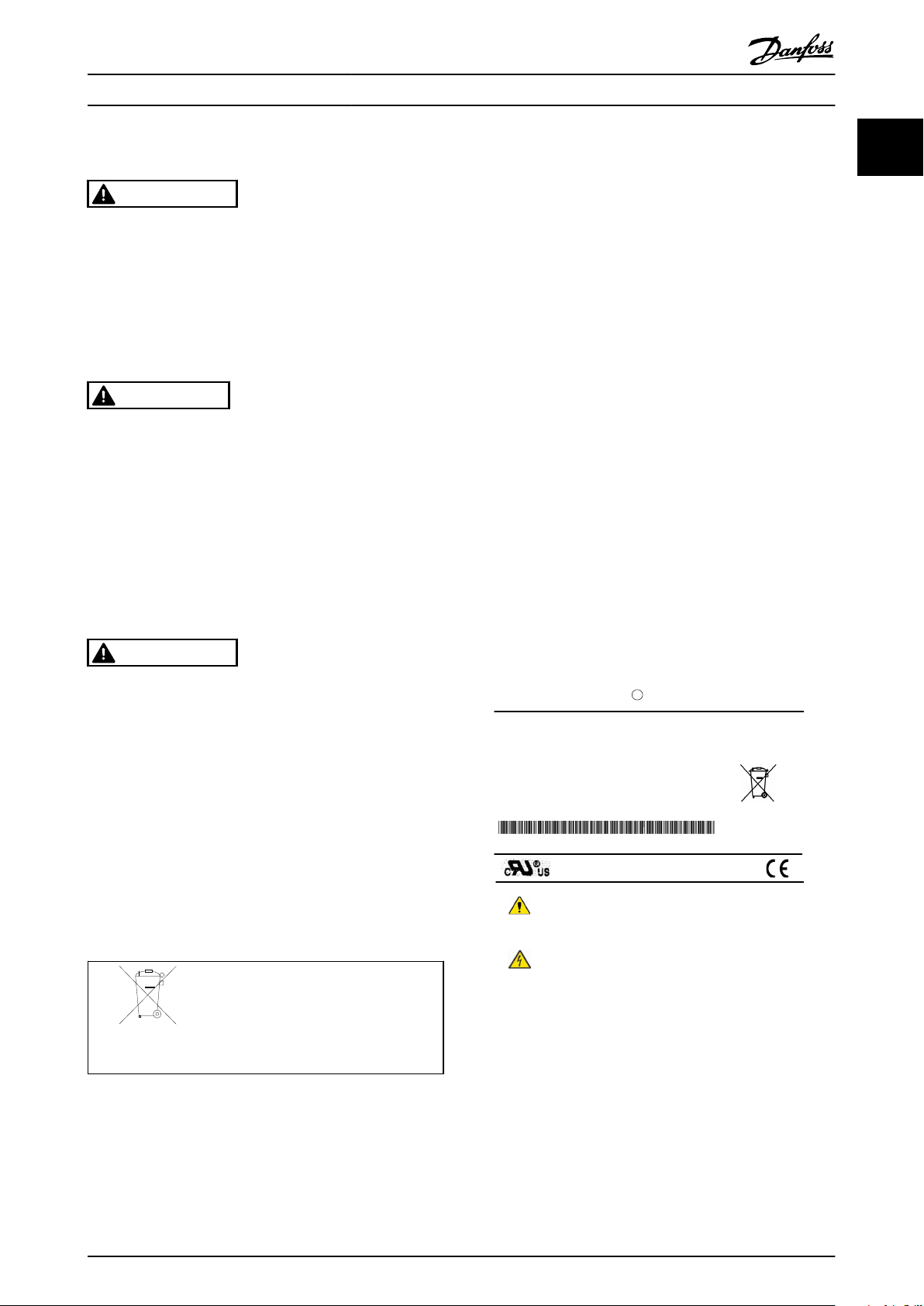
1.8 Product Identification
A product identification label is placed on the drive
chassis. It carries the ordering code i.e. 76L7002. The last 3
digits of the numeric string indicate the production date,
i.e. 062 means week 6 in 2012. Do not remove the identification label from the drive (loss of warranty).
Avoid unintended start
While the variable speed drive is connected to mains, the
motor (compressor) can be started/stopped using serial
communication commands.
- Disconnect the frequency converter from mains
whenever personal safety considerations make it
necessary to avoid unintended start.
1.5
Disposal Instruction
Equipment containing electrical
components may not be disposed
together with domestic waste.
It must be separately collected with
electrical and electronic waste according
to local and valid legislation.
Illustration 1.1 Product Identification Label
1.9 Unpacking the Drive
NOTE
To avoid damage to the drive caused by electrostatic
discharge, people handling the drive should wear wrist
traps for proper grounding at all time!
MG10V402 - VLT® is a registered Danfoss trademark 5
Page 10

General
VLT® Inverter Scroll CDS 801 Operating Instructions
11
1.10 Table of Abbreviations
VSD Variable speed drive
VFD Variable frequency drive, also used instead of VSD
EMC Electromagnetic compatibility
RCD Residual current device
SELV Safety extra low voltage
ESD Electrostatic discharge
PCB Printed circuit board
AWG American wire gauge
EEV Electronic expansion valve
RTU Remote terminal unit
OEM Original equipment manufacturer
AC Air-conditioning
HP Heat pump
RLA Rated load amperage
AOC Application oriented controller
MOC Motor oriented controller
Table 1.2 Abbreviations
6 MG10V402 - VLT® is a registered Danfoss trademark
Page 11

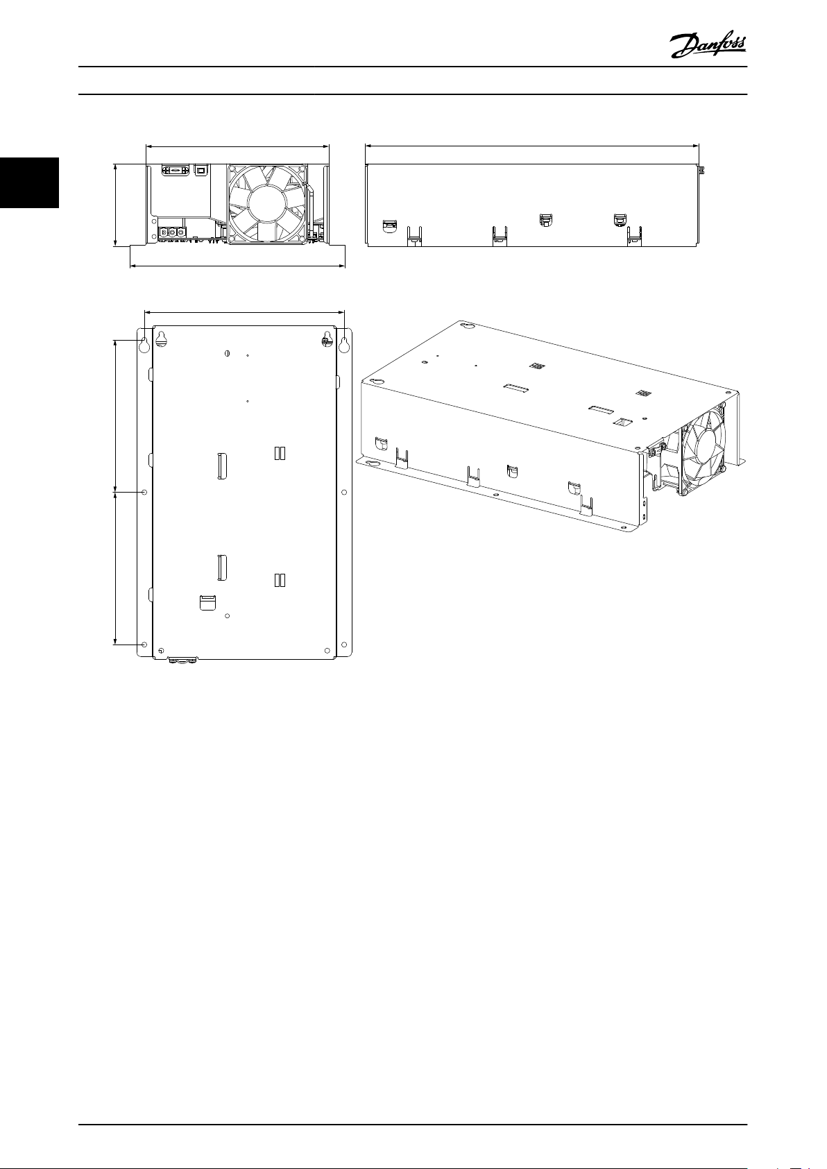
196 mm/7.7 in
374 mm/
14.7 in
175ZB032.13
394 mm/15.5 in
216 mm/8.5 in
255 mm/10 in
98 mm/
3.8 in
Mechanical Installation
2 Mechanical Installation
2.1 Dimensions and Weight
VLT® Inverter Scroll CDS 801 Operating Instructions
2 2
Illustration 2.1 Dimensions
MG10V402 - VLT® is a registered Danfoss trademark 7
Page 12
236 mm/9.3 in
216 mm/8.5 in 394 mm/15.5 in
180 mm/
7.1 in
98 mm/
3.8 in
175ZB031.13
255 mm/10 in
180 mm/
7.1 in
Mechanical Installation
VLT® Inverter Scroll CDS 801 Operating Instructions
22
Illustration 2.2 Dimensions
Mounting holes: ¼ inch, Ø 6 mm
Weight: 10.3 lbs/5.5 kg
8 MG10V402 - VLT® is a registered Danfoss trademark
Page 13
175ZB036.10
175ZB037.10
Mechanical Installation
VLT® Inverter Scroll CDS 801 Operating Instructions
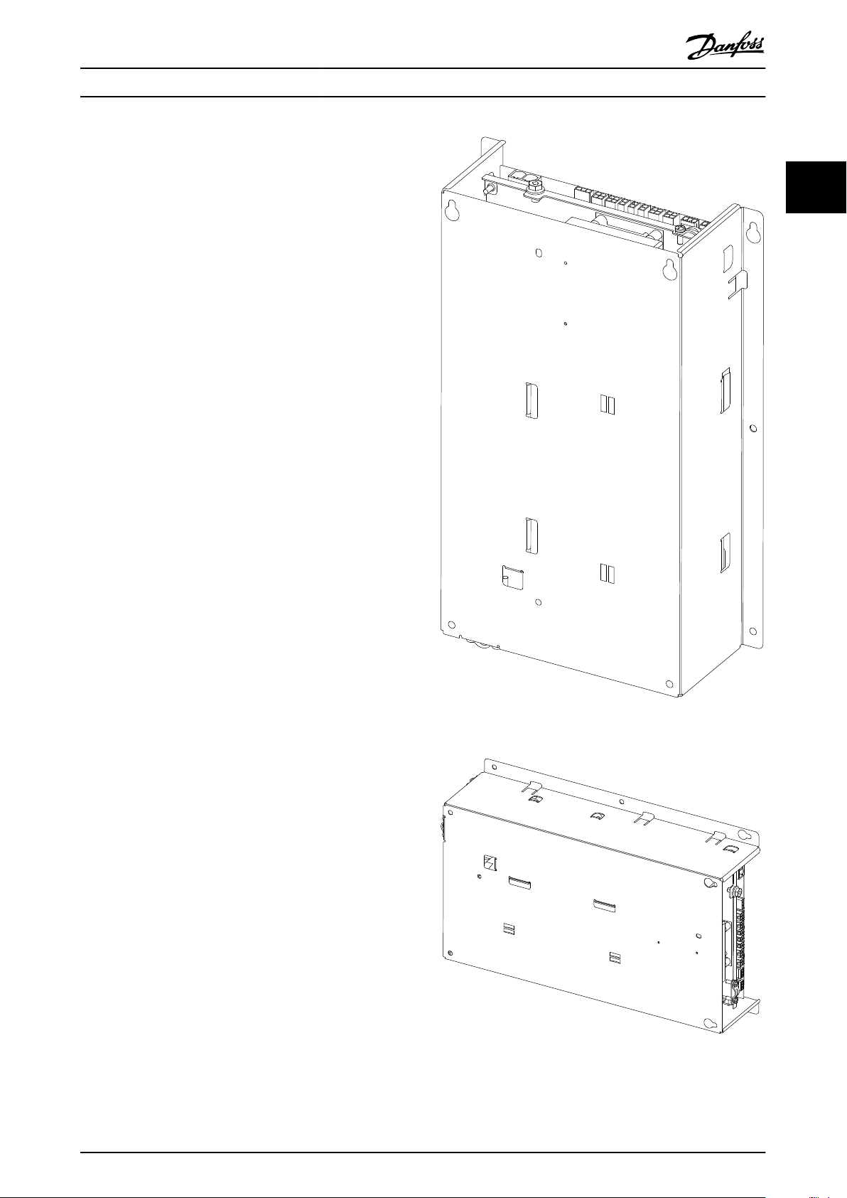
2.2 Installation Orientation and Clearances
2.2.1 Surface Mounting
The drive can be installed horizontally (see Illustration 2.4)
or vertically (see Illustration 2.3) on any plain surface with
the PCB pointing towards the surface. Typically, the 6
mounting holes in the side flaps of the chassis are used for
installation.
For vertical installation, the upper two mounting holes can
be used as suspension holes.
NOTE
If the drive is installed on a sheet metal surface, the
clearance between the drive PCB and the mounting
surface must be observed. As a minimum, sheet metal
gauge 22, 33/1000 inch or 1 mm should be used. If
electrical contact with the mounting surface can not be
avoided an additional isolation foil should be used.
2 2
NOTE
For outdoor units, do not install the drive horizontally with
the PCB in the top or bottom. Water condensing on the
PCB cannot be properly drained.
Illustration 2.3 Horizontal Orientation
Illustration 2.4 Vertical Orientation
MG10V402 - VLT® is a registered Danfoss trademark 9
Page 14
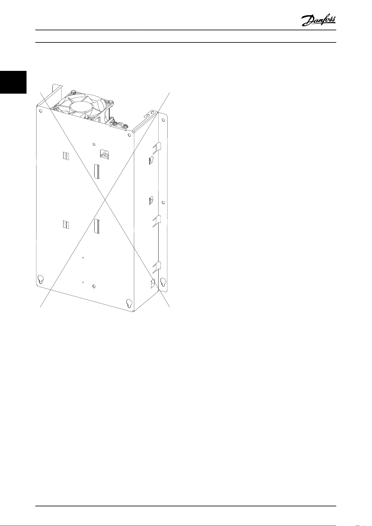
175ZB038.12
Mechanical Installation
To avoid insufficient cooling, do not install the drive with
the cooling fan in the top, see Illustration 2.5.
VLT® Inverter Scroll CDS 801 Operating Instructions
22
Illustration 2.5 Wrong Drive Orientation
10 MG10V402 - VLT® is a registered Danfoss trademark
Page 15

175ZB041.10
175ZB042.10
Mechanical Installation
2.2.2 Structural Mounting
VLT® Inverter Scroll CDS 801 Operating Instructions
The drive can be integrated in any kind of mechanical
structure of air conditioning equipment Illustration 2.6 and
Illustration 2.7.
2 2
Illustration 2.7 Horizontal Installation in Mechanical Structure
CAUTION
During mechanical installation of the drive make sure that
no screws can touch electrical parts on the PCB. Screws
touching the electrical parts on the PCB can cause
personal injury and product damage.
Illustration 2.6 Vertical Installation in Mechanical Structure
MG10V402 - VLT® is a registered Danfoss trademark 11
Page 16
175ZB043.10
Mechanical Installation
VLT® Inverter Scroll CDS 801 Operating Instructions
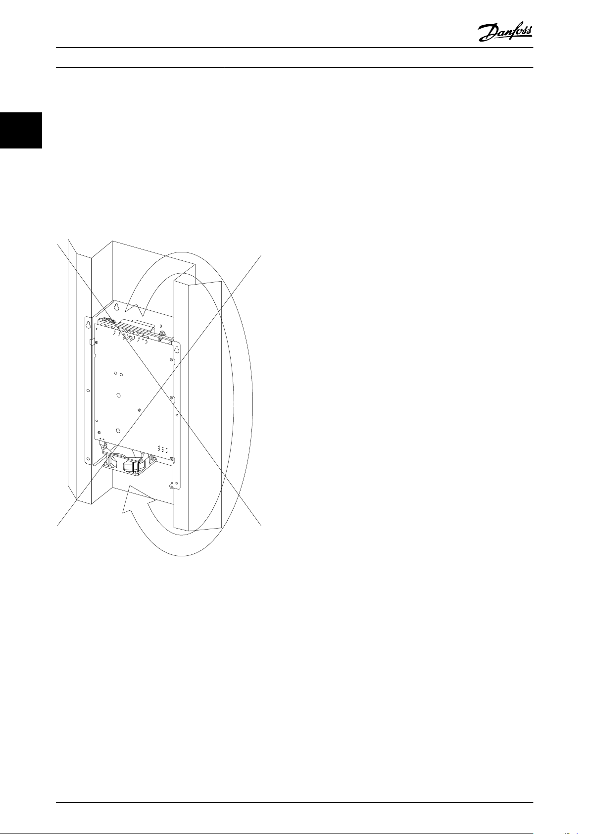
2.3 Air Circulation/Cooling
2.5
The drive must be installed in a way that allows for free
22
airflow. However short circuiting the airflow (warm air reentering the drive’s cooling fan) must be avoided (see
Illustration 2.8). A clearance of 5 inches (12.7 cm) must be
observed in both ends of the drive chassis. Install the drive
in a location where coldest possible air can be drawn into
the drive, i.e. from the bottom part of an outdoor unit.
Counter flow (static pressure) must not restrict the
operation of the internal cooling fan of the drive.
Vibration and Mechanical Resonances
The mechanical structure (sheet metal) carrying the drive
must be designed to withstand vibration and consequently
resonances induced by the compressor or condenser fan.
See vibration specification for the drive further down this
document.
Also refer to 6.3.5.8 Frequency Cancelation explaining the
possibility to program bypass frequencies in the drive to
avoid mechanical resonances of the structure.
Illustration 2.8 Wrong Drive Airflow
2.4
Condensation and Dripping Water
The printed circuit board assembly of the drive is
conformally coated and thus sufficiently protected against
condensation during off time. Nevertheless, the drive
should not be exposed to dripping water (rain) or
condensing water slung around by the condenser fan. In
outdoor units, it is recommendable to install the drive in a
rain proof compartment.
12 MG10V402 - VLT® is a registered Danfoss trademark
Page 17

Electrical Installation
VLT® Inverter Scroll CDS 801 Operating Instructions
3 Electrical Installation
3.1 Electrical Connection in General
NOTE
All cabling must comply with national and local
regulations on cable cross-sections and ambient
temperature. Copper conductors required.
3.2 Tightening Torque
Power supply plug terminals 1.5 Nm/1.1 lbf ft
Ground screw 3.0 Nm/2.2 lbf ft
Motor plug (compressor) 1.5 Nm/1.1 lbf ft
EMC clamp for motor cable 1.5 Nm/1.1 lbf ft
Proper temperature rating of the cable must be observed.
In installations with ambient temperatures above 30 °C
maximum current derating applies, therefore hightemperature cable with 90 °C conductor temperature, e.g.
Nexans Rheyflex is recommended. Copper type cable only.
Maximum cable length 2 m.
Cable specification for installations in North America:
3-wire cable, minimum cross section AWG 10, voltage
rating 600 V, temperature rating 221 °F/105 °C, 2/64
moisture resistant UL style 1230 standard bare copper
type. In North America, standards for radiated emission are
currently not enforced. Furthermore, FCC parts 15
regulations explicitly exempt air-condition devices.
Maximum cable length 7 ft. Local compressor grounding.
3
3
Table 3.1 Tightening Torque
3.3 Cable Quality and Dimensioning
Power supply cable
There is no need for using shielded cable for the supply of
the variable speed drive.
Motor cable
The cable from the drive to the compressor (motor) must
be shielded to comply with EMC regulations for conducted
and radiated emissions in accordance with EN 55011 class
A and EN 55014 (with ferrite). A proper ground connection
of the shield in both ends is essential to obtain the best
suppression of emissions. See also 3.6 Electrical
Connections.
Power Supply Cable Specification
Power connections must be made in accordance with local
and national codes. 2-wire cable plus ground conductor,
minimum AWG 10, voltage rating minimum 300 V,
minimum temp. rating 105 °C/221°F
Min. circuit ampacity
4 t unit 35 A
5 t unit 40 A
Table 3.2 Power-supply Cable Specificatoin
Motor Cable Specification
Depending on the desired level of EMC compliance
according to European or North American standards for
radiated emissions such as EN 55014/55011 or FCC part 15,
a suitable cable connection drive and compressor must be
selected. It is recommended to use shielded cable under
all circumstances.
Cable specification for installations in the EU:
4-wire cable with protective earth (PE) and shield (min 80%
coverage), minimum cross section 4 mm2 for 13 kW units
and 6 mm2 for 16 and 20 kW units, voltage rating 600 V.
3 t unit 30 A
Min. circuit ampacity 13 kW/3 t unit 30 A
16 kW/4 t unit 35 A
20 kW/5 t unit 40 A
Table 3.3 Motor Cable Specification
Sensor and Transmitter Cables
Refer to the documentation provided with the Danfoss
sensors and transmitters.
For serial communication connections, see 4 Serial
Communication (Modbus RTU).
3.4
Fuses/Circuit Breakers
Branch circuit protection
To protect the installation against electrical and fire hazard,
all branch circuits in an installation must be short-circuited
and over-current protected according to national and local
regulations.
Short circuit protection
Danfoss requires using the fuses mentioned in Table 3.4 to
protect service personnel or other equipment in case of an
internal failure in the unit or short-circuit on DC-link of the
drive. The variable speed drive provides full short circuit
protection in case of a short-circuit on the motor output in
accordance with UL regulations.
Over-current protection
Overload protection must be provided to avoid
overheating of the cables in the installation. Over-current
protection must always be carried out according to
national regulations (NEC Article 430 “Motors, Motor
Circuits and Controllers” and NEC Article 440 “Airconditioning and refrigeration equipment”).
MG10V402 - VLT® is a registered Danfoss trademark 13
Page 18

Electrical Installation
Fuses
13 kW/3 t unit 176L0767 RLA 22A max. fuse amperage 30 A
16 kW/4 t unit 176L0766 RLA 28A max. fuse amperage 35 A
20 kW/5 t unit 176L0765 RLA 33A max. fuse amperage 40 A
VLT® Inverter Scroll CDS 801 Operating Instructions
3
Table 3.4 Fuses
NOTE
Fuses of type class RK5 must be used in US installations.
Recommended circuit breakers
HVCR type fusible circuit breaker may be used, see rating
above.
3.5 EMC Correct Installation
Follow these guidelines when compliance with EN 55011
cl. A or EN 55014 is required.
Good engineering practice to ensure EMC-correct electrical
installation:
Use only shielded/braided screened/armored
•
motor cables and control cables. The shield
should provide a minimum coverage of 80%. The
shield material must be metal, not limited to but
typically copper, aluminum, steel or lead. There
are no special requirements for the mains cable.
Connect the shield to ground at both ends for
•
motor cables and control cables.
Avoid terminating the shield with twisted ends
•
(pigtails). Such a termination increases the high
frequency impedance of the screen, which
reduces its effectiveness at high frequencies. Use
low impedance cable clamps (delivered with the
drive) and EMC glands instead.
Ensure good electrical contact between the de-
•
coupling plate and the metal chassis of the
variable speed drive.
Where possible, avoid using unshielded/
•
unarmored motor or control cables inside
cabinets housing the drive.
14 MG10V402 - VLT® is a registered Danfoss trademark
Page 19

175ZB044.10
175ZB045.10
Electrical Installation
VLT® Inverter Scroll CDS 801 Operating Instructions
3.6 Electrical Connections
3.6.1 Routing of Motor and Supply Cable
Do not route supply, sensor and communication cables in
parallel with the motor cable. Separate cables from each
other as much as possible (see Illustration 3.2).
Furthermore, the motor cable should be kept as short as
possible.
Do not route cables across the PCB (see Illustration 3.1).
3
3
Illustration 3.1 Wrong Routing of Motor and Supply Cables
Illustration 3.2 Cable Separation
MG10V402 - VLT® is a registered Danfoss trademark 15
Page 20

175ZB052.11
L1
L2/N
T1
C
T3
A
T2
B
T1
C
T3
A
T2
B
130ZB122.10
T
3
T
1
T
2
R
C
S
175ZB047.10
3
Electrical Installation
VLT® Inverter Scroll CDS 801 Operating Instructions
3.6.2 Power Supply Connection (Mains)
1. Connect the ground cable.
2.
Connect L2 or L1 and N, see Illustration 3.3.
Mains cables must be dimensioned according to national
and local standards.
Illustration 3.3 Power Supply Connections
Motor (Compressor) Connection
3.6.3
Danfoss offers different compressor models according to
the desired level of EMC compliance for radiated
emissions. Compressors for installations in the EU have a
rectangular terminal box with provision for using EMC
gland sets for shielded cable, while the models for installations in North America have a round shaped terminal
box (see Illustration 3.4 and Illustration 3.5).
The order of phases is inevitable in both cases. Always
connect T1 on the drive with T1 on the compressor and T2
and T3 accordingly, see Illustration 3.7.
Observe maximum current ratings for spade type angular
cable connectors according to manufacturer’s product
data.
Illustration 3.4 Motor (Compressor) Connection, EU Models
EU models:
The terminal box provides punch outs on the right side for
25 mm glands and in the bottom for 28 mm glands.
Connect wires for T1, T2, T3 and ground (PE) inside the
terminal box and install EMC cable gland set accordingly.
NAM models:
Connect wires for T1, T2, T3 and local grounding.
Illustration 3.5 Motor (Compressor) Connection, NAM Models
16 MG10V402 - VLT® is a registered Danfoss trademark
Page 21

C
UP
T1
R
T3
T2
S
175ZB132.10
175ZB046.11
T3 T2 T1
130ZB123.10
Electrical Installation
VLT® Inverter Scroll CDS 801 Operating Instructions
3
3
Illustration 3.6 Connection Box, Europe/Asia
Illustration 3.7 Motor (Drive) Connection
Use of Ferrite on drive output terminals:
To comply with the most stringent standard for radiated
emissions (EN 55011 cl. B) a ferrite must be installed at the
output terminals of the drive as shown in Illustration 3.8.
The motor phase wires (T1, T2, T3) must be wound twice
around the ferrite, while the PE wire is directly connected
to the chassis, see Illustration 3.8.
Illustration 3.8 Wire Routing on Ferrite
MG10V402 - VLT® is a registered Danfoss trademark 17
Page 22

175ZB048.11
P_C
P_O
S_D
S_AUX
S_AMBIENT
175ZB049.11
RLY_1
175ZB051.11
EXT_FAN
175ZB099.11
EEV_2
Electrical Installation
VLT® Inverter Scroll CDS 801 Operating Instructions
3
3.6.4 Sensor Connections
Connect the sensors as marked on the PCB, see
Illustration 3.9:
Aux. temperature sensor (S aux.) (if applicable)
Compressor discharge temperature (Sd)
Ambient temperature (S amb.)
Compressor suction pressure (P0)
Compressor discharge pressure (Pc)
Condenser Fan Motor Control
3.6.6
Connection (EXT_FAN)
Two different control signals are available, 0-10 V (max.
current 20 mA) analogue output and 24 V PWM duty cycle
with scalable frequency, see Modbus register description in
5 Commissioning. Connect the control signal of the
condenser fan (or any other external device like a
circulator pump) as shown and marked on the PCB, see
Illustration 3.11.
Illustration 3.9 Sensor Connections
4-way Reversing Valve Connection
3.6.5
The relay for the 4-way reversing valve is connected as
shown and marked on the PCB, see Illustration 3.10.
Max. load:
250 V AC, 4 A
24 V DC, 4 A
See 3.6.10 Allocation of Connector Pins.
Illustration 3.10 4-way Reversing Valve Connection
Illustration 3.11 Condenser Fan Motor Control Connection (EXTFan)
EEV Controller (HP Mode) Connection
3.6.7
(EEV_2)
Connect the EEV Controller as shown and marked on the
PBC, see Illustration 3.12.
Illustration 3.12 EEV_2 Controller Connection
18 MG10V402 - VLT® is a registered Danfoss trademark
Page 23

175ZB024.12
Shield
MASTER
EEV_1
Electrical Installation
VLT® Inverter Scroll CDS 801 Operating Instructions
3.6.8 Serial Communication Cable Connection
Connect the RS-485 cable(s) to the PCB of the Variable Speed Drive as follows, see Illustration 3.13:
1. Attach the positive (+) polarity wire to the screw terminal.
2. Attach the negative (-) polarity wire to the screw terminal.
3. Attach the drain cable to the drain terminal (D).
4. Attach the cable with the shield to the compression clamp on the chassis.
5. Connect the other end of the RS-485 cable to the OEM Controller ensuring that the polarity of the wires matches
the polarity at the drive.
The two 3-pole connectors are marked on the circuit board as “Master” which connects to the OEM Controller, and “EEV_1”
which connects to the indoor EEV Controller (separate internal Danfoss bus).
The compression clamp is suitable to two sets of cable. Make sure to establish a good connection between the shield and
the compression clamp and the chassis.
3
3
Illustration 3.13 Serial Communication Connection Cable
When selecting a transmission line for RS-485, it is necessary to examine the required distance of the cable and the data
rate of the system. Losses in a transmission line are a combination of AC losses (skin effect), DC conductor loss, leakage, and
AC losses in the dielectric. In high-quality cable, the conductor losses and the dielectric losses are on the same order of
magnitude.
The recommended maximum Modbus cable length between the drive and the OEM Controller should not exceed 100 ft (30
m).
While the RS-485 specification does not specify cabling, the recommendation is 24 AWG shielded twisted-pair cable with a
shunt capacitance of 16 pF/ft and 100 Ω impedance.It is also possible to use the same cable commonly in the twisted-pair
Ethernet cabling. This cable is commonly referred to as Category 5 cable. The cable has a maximum capacitance of 17 pF/ft
(14.5 pF/ft typical) and characteristic impedance of 100 Ω.
MG10V402 - VLT® is a registered Danfoss trademark 19
Page 24

175ZB055.10
175ZB033.10
175ZB054.10
175ZB034.10
175ZB056.10
3
Electrical Installation
VLT® Inverter Scroll CDS 801 Operating Instructions
3.6.9 Connector Specification
All counterpart plugs listed in Table 3.5 are of female type, all connectors installed on the PCB are of male type.
Connector Poles Manufacturer Type Color Remarks
Supply (L1,L2) 2 Phoenix Contact PC 16/2-ST-10,16 Green Marked L1, L2
Motor (T1, T2,T3) 3 Phoenix Contact PC 16/3-ST-10,16 Green Marked T1, T2, T3
Indoor EEV Controller (EEV_1) 3 Dinkel EC381R-4620-03P Green Marked RS-485, +, -, D
Modbus Master bus (MASTER) 3 Dinkel EC381R-4620-03P Green Marked RS-485, +, -, D
Outdoor EEV Controller (EEV_2) 4 Molex 39-01-2040 White
Condenser fan speed ref. (EXT_FAN) 4 Molex 39-01-2040 White
Ambient temperature (S_AMBIENT) 2 Molex 39-01-2020 White
Auxiliary temperature (S_AUX) 2 Molex 39-01-2020 White
Compressor discharge temp. (S_D) 2 Molex 39-01-2020 White
Compressor suction pressure (P_0) 4 Molex 39-01-2040 White
Compressor discharge pressure (P_C) 4 Molex 39-01-2040 White
Reversing valve relay (RLY_1) 3 Molex 39-01-4030 White
Cooling fan (INT_FAN) 3 Molex 39-01-4030 White
Crimping contact Manufacturer Type
All connectors Molex 39-00-0213
Alternative manufacturer see manuf. reference lists
Table 3.5 Connector Specification
Illustration 3.14 2-pole Connector
Illustration 3.15 3-pole Connector
Illustration 3.16 4-pole Connector
Illustration 3.17 Bus Connector
20 MG10V402 - VLT® is a registered Danfoss trademark
Illustration 3.18 Crimping Contact
Page 25

12
34
1 12
2
1
2
1
234
12
34
1 12 2
3
3
4
EEV_2
1 Ground
2 + (RS485)
3 - (RS485)
4 +24V
EXT_FAN
1 Ground
2 0-10V
3 PWM
4 not used
S_AMBIENT, S_AUX, S_D
1 PT1000
2 PT1000
P_O
1 Ground
2 Signal
3 +5V
4 not used
P_C
1 Ground
2 Signal
3 +5V
4 not used
RLY_1
1 NC
2 COM
3 NO
175ZB057.10
Electrical Installation
VLT® Inverter Scroll CDS 801 Operating Instructions
3.6.10 Allocation of Connector Pins
The position of the connector pins for sensors, transmitters, serial communication, etc. is shown in Illustration 3.19.
NOTE
All connections are seen from the cable side
Illustration 3.19 Allocation of Connector Pins
3
3
MG10V402 - VLT® is a registered Danfoss trademark 21
Page 26

Main power supply
208-230V 60 Hz
distribution
Condenser
fan motor
i.e. ECM 142
High-pressure
switch
Safety
circuit
breaker
Fuse
Fuse
Optional
Not scope of Danfoss delivery
Compressor,
order of phases
must be observed!
T1
T1
T2
T2
T3
T3
Chassis
L1 L2
Modbus serial
communication
with OEM controller
Modbus serial
communication
with indoor EEV
controller
EEV_1
EEV_2
MASTER
EXT_FAN
S_AMBIENT
S_AUX
S_D
P_O
P_C
RLY_1
Inverter PCA
Outdoor unit
Indoor unit
Indoor unit
temp. sensor
PT 1000(S2)
Schematic Wiring Diagram
Air-Conditioning System
Agenda:
Low voltage
High voltage
Prefabricated cable
Screended cable
Power supply
indoor EEV
controller
18-30 v AC/DC
EEV
Outdoor
unit
EEV
Controller
OEM
Controller
(Thermostat)
Ambient temperature
sensor PT 1000(S. amb.)
Compr. dischange temp.
sensor PT 1000(Sd)
Compressor suction
pressure sensor (Po)
Compressor discharge
pressure sensor (Pc)
Aux. temperature
sensor PT 1000
175ZB100.10
3
Electrical Installation
VLT® Inverter Scroll CDS 801 Operating Instructions
3.6.11 Overview Wiring Diagram
The following 3 wiring diagrams show typical system configurations for an AC system (see Illustration 3.20), a combined
AC/HP system (see Illustration 3.21) and a ground source heat pump system (see Illustration 3.22), with all Danfoss
components.
Illustration 3.20 AC only System
22 MG10V402 - VLT® is a registered Danfoss trademark
Page 27

Main power supply
208-230V 60 Hz
distribution
Condenser
fan motor
i.e. ECM 142
High-pressure
switch
Not scope of Danfoss delivery
Compressor,
order of phases
must be observed!
Modbus serial
communication
with OEM controller
Modbus serial
communication
with indoor EEV
controller
Inverter PCA
Outdoor unit
Ambient temperature
sensor PT 1000(S. amb.)
Compr. dischange temp.
sensor PT 1000(Sd)
Compressor suction
pressure sensor (Po)
Compressor discharge
pressure sensor (Pc)
Aux. temperature
sensor PT 1000
T1
T2
T3
T1
T2
T3
L1 L2
EEV_1
EEV_2
MASTER
EXT_FAN
S_AMBIENT
S_AUX
S_D
P_O
P_C
RLY_1
Safety
circuit
breaker
Chassis
Fuse
Fuse
Optional
Indoor unit
Indoor unit
temp. sensor
PT 1000(S2)
Schematic Wiring Diagram
Combined Air-Conditioning
and Heat Pump System
Agenda:
Low voltage
High voltage
Prefabricated cable
Screended cable
Power supply
indoor EEV
controller
18-30 v AC/DC
175ZB101.10
EEV
Outdoor
unit
EEV
Controller
EEV
Outdoor
unit
EEV
Controller
OEM
Controller
(Thermostat)
4-way
reversing
valve
Coil
supply according
to coil
i.e. 230 or 24VAC
Electrical Installation
VLT® Inverter Scroll CDS 801 Operating Instructions
3
3
Illustration 3.21 Combined AC/HP System
MG10V402 - VLT® is a registered Danfoss trademark 23
Page 28

Main power supply
208-230V 60 Hz
distribution
High-pressure
switch
Not scope of Danfoss delivery
Compressor,
order of phases
must be observed!
Safety
circuit
breaker
4-way
reversing
valve
Coil
L1 L2
Chassis
T1
T2
T3
T1 T2 T3
Inverter PCA
EEV_1
EEV_2
MASTER
EXT_FAN
S_AMBIENT
S_AUX
S_D
P_O
P_C
RLY_1
Modbus serial
communication with
EEV controller
Modbus serial
communication with
OEM controller
Compact unit
Schematic Wiring Diagram
Combined Air-Conditioning
and ground source Heat
Pump System
Agenda:
Low voltage
High voltage
Prefabricated cable
Screended cable
175ZB102.12
Indoor unit
temp. sensor
PT 1000(S2)
EEV
unit
EEV
Controller
OEM
Controller
(Thermostat)
Ambient temperature
sensor PT 1000(S. amb.)
Compr. discharge temp.
sensor PT 1000(Sd)
Compressor suction
pressure sensor (Po)
Compressor discharge
pressure sensor (Pc)
Aux. temperature
sensor PT 1000
supply according
to coil type
i.e. 230 or 24VAC
3
Electrical Installation
VLT® Inverter Scroll CDS 801 Operating Instructions
Illustration 3.22 Ground Source Heat Pump System with one EEV
24 MG10V402 - VLT® is a registered Danfoss trademark
Page 29

OEM
Controller,
Modbus
Master
Indoor EEV
Controller for
AC operation
Modbus node #165
RS 485
Interfaces
Application control
Microprocessor
Modbus node #162
Motor control
Microprocessor
Modbus node #163
Outdoor EEV
Controller for
Heatpump operation
Modbus node #164
Drive PCB
Internal bus
Outdoor sectionIndoor section
175ZB023.12
Serial Communication (Modbu...
VLT® Inverter Scroll CDS 801 Operating Instructions
4 Serial Communication (Modbus RTU)
General
The serial communication bus is used to receive Modbus Slave Messages from an external source. In normal operation, this
will be a Modbus Master usually called the “OEM Controller”. When not in service, the OEM or manufacturing can access the
device for configuration or service, see Illustration 4.1 and Illustration 4.2.
NOTE
The Modbus communication is available after the drive has performed an internal test routine, approximately 15 seconds
after power up.
The Modbus implementation has been designed to conform to the Modbus Standard Protocol.
For details, refer to
Modbus Application Protocol Specification, V1.1b
•
Modbus Over Serial Line Specification and Implementation Guide, V1.02
•
Modicon Modbus Protocol Reference Guide
•
PI–MBUS–300 Rev. J
4 4
Also visit www.modbus.org
For details about setting up the Modbus serial communication, refer to the Modbus RTU Communication Setup Manual.
Illustration 4.1 Modbus Communication Set-up, for AC only, and Combined AC/HP Systems
MG10V402 - VLT® is a registered Danfoss trademark 25
Page 30

OEM
Controller,
Modbus
Master
EEV
Controller
Modbus node #165
RS 485
Interfaces
Application control
Microprocessor
Modbus node #162
Motor control
Microprocessor
Modbus node #163
Drive PCB
Internal bus
175ZB129.10
Serial Communication (Modbu...
VLT® Inverter Scroll CDS 801 Operating Instructions
44
Illustration 4.2 Modbus Communication Set-up for Ground Source Heat Pump Systems
26 MG10V402 - VLT® is a registered Danfoss trademark
Page 31

Commissioning
VLT® Inverter Scroll CDS 801 Operating Instructions
5 Commissioning
5.1 Initial Configuration of the Performer
VSD sub-system
System components offered by the OEM, such as outdoor
units, indoor units/air handlers, evaporator modules or
furnaces are often manufactured in different locations and
first merged into a complete system at the end user’s site.
Furthermore, numerous combinations of such components
are feasible. Therefore it is extremely important to prepare
the components during manufacturing for a late merge in
the field.
Alternatively, the configuration of each individual
component can be made in the field. This can be done
with Danfoss Update tool or Modbus tool allowing
programming the drive, application controller and EEV
Controller via the serial communication interface (Modbus
RTU).
This functionality can also be incorporated in the OEM
Controller by establishing a protected service menu,
allowing accessing all Modbus registers.
Individual solutions can be worked out in cooperation with
the product support team.
5.2
Drive Setup
The variable speed drive including the embedded
application controller and the EEV Controller(s) can be
individually configured by setting various parameters
(Modbus registers). This manual is limited to the drive
parameters. For the application controller and the EEV
Controller(s), refer to the separately provided documentation.
NOTE
Changing the setting of some registers requires re-booting
before the setting becomes effective. For details, refer to
the Modbus RTU Communication Setup Manual.
The timeouts and response times of Modbus messages to
and from the drive is in accordance with the Modbus
standard.
5.2.1
Drive Parameters
(Modbus Registers, node 162)
Register 40001-40010, PCA Bar Code (read only)
These registers (10) allow reading the bar code information
on the PCA, which is also found on the product identification label on the drive chassis.
Register 40011-40020, Ordering code (read only)
These registers (10) allow reading the Danfoss ordering
code, which is also found on the product identification
label on the drive chassis, typically starting with 176L…..
Register 40021 and 40022, Operation Time Counter (read
only)
These registers allow reading the accumulated time the
drive has been powered. The value is given in seconds.
Register 40101-40110, AOC Software Version (read only)
These registers (10) allow reading the software version
number for the application oriented microprocessor.
Register 40111-40120, AOC Registers Version (read only)
These registers (10) allow reading the registers version
number for the application oriented microprocessor.
Register 40121 and 40122, Drive Status
These registers describe the exact operation condition of
the system in a 32 bit structure. See separate description
in 7 Fault Conditions, Messages and Causes.
Register 40131, OEM Reset
Setting this register to logic “1” resets the drive to the
OEM defaults (configuration defaults set by the OEM in
production) stored in the EEPROM.
Register 40132, Danfoss Reset
Setting this register to logic “1” resets the drive to the
Danfoss defaults (factory defaults as listed in this manual
and Modbus register map files)
Register 40133, Overwrite Defaults
Setting this register to logic “1” allows overwriting the
factory defaults. This should only be done with assistance
from Danfoss.
NOTE
Do not set registers 40132 and 40133 to logic “1” at the
same time.
5 5
In the following chapters, the drive parameters are
described by the register number.
MG10V402 - VLT® is a registered Danfoss trademark 27
Page 32

Commissioning
VLT® Inverter Scroll CDS 801 Operating Instructions
Register 40134, Test Register
This register has been created as a test tool to verify
proper Modbus communication. To test the communication, write any value between 0 and 65535 to the
register and verify that the same value is successfully
reported back from the slave node (drive).
Register 40135, Drive Reboot
Setting this register to logic “1” initiates a reboot
sequence; this equals cycling power to the drive.
Register 40141, OEM baud rate (default 19200)
This register allows setting the baud rate for the Modbus
55
serial communication.
Value
0 9600 kbps
1 19200 kbps
Register 40146, EEV Indoor Unit Address (def. 165, min 1,
max 247)
This register allows setting the bus address (node address)
of the EEV Controller in the indoor unit. The default
address is 165 and can be set to a value between 1 and
247.
NOTE
Must be set to the same value on EEV Controllers.
Register 40147, EEV Outdoor Unit Address (def. 164, min 1,
max 247)
This register allows setting the bus address (node address)
of the EEV Controller in the outdoor unit (if applicable, in
systems with 2 EEV’s only). The default address is 164 and
can be set to a value between 1 and 247.
NOTE
Table 5.1 OEM Baud Rate
Register 40142, OEM Parity
This register allows setting the Parity of the Modbus
protocol.
Value
0 None
1 Odd
2 Even (default)
Table 5.2 OEM Parity
Register 40143, OEM Stop Bits
This register allows setting the number of stop bits of the
Modbus protocol.
Value
1 1 stop bit (default)
2 2 stop bits
Must be set to the same value on EEV controllers.
Register 40148, OEM Communication Timeout (def. 20 sec,
min 0 sec, max. 3600 sec)
The time set in this register determines the duration from
loosing communication with the OEM controller to
stopping the system. When communication is reestablished, the drive will resume operation automatically.
Setting this register to 0 sec. means that the drive will not
stop in case of loosing communication.
Registers 40499 and 40500, Sensor S_AUX
These registers allow reading the temperature reading of
the auxiliary sensor input S_AUX in degrees centigrade
(°C); in case a PT 1000 sensor is connected.
Register 40501-40550, OEM Data registers
Danfoss has established 50 OEM registers that the OEM
customer can use freely to store product information. All
registers are of type unsigned 16.
Drive Parameters
Table 5.3 OEM Stop Bits
5.2.2
(Modbus Registers, node 163)
Register 40144, Drive AOC Address (def. 162, min 1, max
247)
This register allows setting the bus address (node address)
of the application oriented microprocessor of the drive.
The default address is 162 and can be set to a value
between 1 and 247.
Register 40145, Drive MOC Address (def. 163, min 1, max
247)
This register allows setting the bus address (node address)
of the motor oriented microprocessor of the drive. The
default address is 163 and can be set to a value between 1
and 247.
NOTE
The same address must be set in MOC register 40145.
28 MG10V402 - VLT® is a registered Danfoss trademark
Register 40101-40110, MOC Software Version (read only)
These registers (10) allow reading the software version
number for the motor control oriented microprocessor.
Register 40111 and 40120, MOC Registers Version (read
only)
These registers (10) allow reading the register version
number for the motor control oriented microprocessor.
Register 40131, OEM Reset
Setting this register to logic “1” resets the drive to the
OEM defaults (configuration defaults set by the OEM in
production) stored in the EEPROM.
Register 40132, Danfoss Reset
Setting this register to logic “1” resets the drive to the
Danfoss defaults (factory defaults as listed in this manual
and Modbus register map files)
Page 33

Commissioning
VLT® Inverter Scroll CDS 801 Operating Instructions
Register 40133, Overwrite Defaults
Setting this register to logic “1” allows overwriting the
factory defaults. This should only be done with assistance
from Danfoss.
Register 40134, Test Register
This register has been created as a test tool to verify
proper Modbus communication. To test the communication, write any value between 0 and 65535 to the
register and verify that the same value is successfully
reported back from the slave node (drive).
Register 40145, Drive MOC Address (def. 163, min 1, max
247)
This register allows setting the bus address (node address)
of the motor control oriented microprocessor of the drive.
The default address is 163 and can be set to a value
between 1 and 247.
Register 40201 and 40202, Compressor Power
Consumption in kWh (read only)
These registers allow reading the power consumption of
the compressor.
Register 40203 and 40204, Compressor Power in kW (read
only)
These registers allow reading the input power to the
compressor.
Register 40205 and 40206, Supply Voltage (read only)
These registers allow reading the supply voltage (line
voltage) applied to the drive.
Register 40207 and 40208, Inverter Temperature (read
only)
These registers allow reading the internal inverter
temperature measured in the power module of the drive
in °C.
Register 40209 and 40210, UDC Voltage (read only)
These registers allow reading the DC voltage in the
intermediate circuit of the drive.
Register 40211 and 40212, Internal Fan Speed (read only)
These registers allow reading the speed of the integrated
cooling fan in the drive in a percentage.
5.3
Condenser Fan Speed Reference Output
When the condenser fan speed control mode is selected in
the application controller the drive calculates the optimum
fan speed for efficiency optimization and provides a speed
reference output signal for the variable speed condenser
fan motor. When the speed control is deselected the
output can be used to control any other external device
such as a circulator pump in a ground source heat pump,
simply by using the Modbus external speed register and
the control signal describe hereinafter.
The following signals are simultaneously available:
Analog output 0-10 V
•
Frequency duty cycle output 24 V PWM, 0-10 kHz
•
Reg. 41609 and 41610, Outdoor fan capacity PCT min
Reg. 41611 and 41612, Outdoor fan capacity PCT max
Reg. 41613 and 41614, Outdoor fan control signal freq
5.4 Crankcase Heating
The variable speed drive comprises an electronic crankcase
heating, by injecting a DC voltage to the compressor
motor. The resulting current heats the motor windings and
therewith effectively prevents refrigerant from accumulating in the compressor sump. An additional heating belt
is not required.
Register 40479 and 40480 Crankcase heating on
temperature (min 50 °F/10 °C, max +77 °F/+25 °C)
This register allows setting the temperature at which the
crankcase heating is activated. Setting register 40481 to
value "0" deactivates the crankcase heating function
permanently (default is "1"/ON).
The temperature equals the ambient temperature
measured by the drive in the outdoor unit.
NOTE
The crankcase heating is not active when power is disconnected to the drive as well as when the compressor is in
operation. Crank case heating will also not be active when
drive is stopped because of an alarm.
The power consumption of the crankcase heating is
approximately 40 W.
5.5
Ambient Temperature Source
The ambient temperature value can be provided from a
sensor connected directly to the drive, or it can be sent to
the unit via Modbus from the OEM controller.
Register 40216, Thermo in Ambient Temperature
An internal analog value from the ambient temperature
sensor connected to the drive at the S_Amb input. (-999
°C if not connected).
Register 40225, Thermo In External Ambient Temperature
The OEM controller writes the ambient temperature via
Modbus. When using the Modbus ambient temperature
signal, the OEM controller it must update the signal at
least every 60 s. Otherwise the drive goes into safe mode.
Register 40484, Thermo Setup Ambient Temperature
Source
Selects the source of ambient temperature used by
software control algorithms (Crankcase Heating and
Outdoor Fan Control).
5 5
MG10V402 - VLT® is a registered Danfoss trademark 29
Page 34

Commissioning
VLT® Inverter Scroll CDS 801 Operating Instructions
0 = 40216 Thermo In Ambient Temperature
1 = 40225 Thermo In External Ambient
Temperature
Default value of the register is 0, and therefore a
temperature sensor must be connected to the drive as
default unless this register is set to 1. It is important that
the ambient temperature value is a true measurement of
the ambient temperature outside the enclosure containing
the compressor and the drive. This value is used for
(crankcase heating and fan control).
55
5.6 Pressure sensor scaling
When using other pressure sensors than Danfoss AKS
sensors (specified in the sensor selection guide), the
pressure configuration registers must be changed to match
the range of the used sensors.
Register 41601 and 41602, Suction pressure min
Register 41603 and 41604, Suction pressure max
Register 41605 and 41606, Condenser pressure
min
Register 41607 and 41608, Condenser pressure
max
All pressure calculations in the drive is done in an absolute
pressure scale (atmospheric pressure = 1bar).
Example: Absolute pressure range 0-20 bar ⇒ pressure min
= 0 and pressure max = 20.
Optional Commands:
Optional available information:
The drive and the EEV Controller(s) allow reading a large
number of data to be polled by the Modbus Master (OEM
Controller), such as:
Setpoint and room temperature (in closed loop
•
operation)
Capacity request (in open loop operation)
•
Dehumidification Mode
•
Product identification
•
Operation status (alarms and warnings)
•
Operation data
•
Power consumption
•
Compressor speed
•
Pressure and temperature values
•
Etc.
•
If a pressure sensor with a gage pressure range is used
(atmospheric pressure = 0 bar), the min and max pressure
must be added with 1 to compensate for the offset in the
range when configuring the sensor.
Example: gage pressure scale 0-20 bar ⇒ pressure min = 1
and pressure max = 21.
5.7
Normal Operation
NOTE
After connecting power to the drive, wait at least 15
seconds until the initialization is completed before
accessing the Modbus communication.
Mandatory commands:
To operate the system a minimum number of commands
must be provided by the OEM
Controller:
Start
•
Stop
•
Reboot
•
30 MG10V402 - VLT® is a registered Danfoss trademark
Page 35

Indoor
Outdoor
Modbus
OEM
control
Modbus
Air flow
Air flow
EIM 316
S4
S2 AC
24V
Galvanic
Isolation
S4
S2 AC
+24V
Drive
P
o
P
c
Sd
Sd
Samb
P
o
Pc
Samb
175ZB116.10
Embedded Application Contro...
VLT® Inverter Scroll CDS 801 Operating Instructions
6 Embedded Application Controller “Thermo Control”
6.1 Introduction
The Residential Variable Speed Drive system is consisting of compressor, variable speed drive, application controller,
Electronic Expansion Valves (EEV), EEV controller and sensors.
Variable Speed Drive and EEV controller are set to be able to communicate using Modbus RTU protocol. Communication
details are available in the Modbus Communication Set-up Manual. Establishing the communication and configuring the
system requires individual parameters settings. These settings must be done through the OEM controller or any other PC
tool, using the Modbus communication.
This chapter describes the operation modes of the application controller. Included is also the parameter lists and parameter
descriptions.
6.2 Applications
6.2.1 Generic AC
6
6
Illustration 6.1 Generic AC
MG10V402 - VLT® is a registered Danfoss trademark 31
Page 36

OutdoorModbus
Indoor
S2 AC
S4
Air flow
Air flow
OEM
control
S2 HP
+24VModbus
Modbus
Drive
Galvanic
isolation
24V
S2
AC
S4
EIM 316
EIM 316
S2
HP
P
c
P
o
Sd
Samb
Pc
P0
Sd
Samb
175ZB117.10
6
Embedded Application Contro...
6.2.2 Generic AC/HP (Reversible)
VLT® Inverter Scroll CDS 801 Operating Instructions
Illustration 6.2 Generic AC/HP (Reversible)
32 MG10V402 - VLT® is a registered Danfoss trademark
Page 37

175ZB118.10
Drive
OEM
control
P
o
P
c
Sd
Samb
Pc
S2
S2
Sd
ModBus +24V
Po
Embedded Application Contro...
VLT® Inverter Scroll CDS 801 Operating Instructions
6.2.3 Ground Source Heat Pump (Reversible)
6
6
Illustration 6.3 Ground Source Heat Pump (Reversible)
6.3
Application Controller
6.3.1 Introduction
The Thermo Controller is an integrated part of the VLT
Inverter Scroll CDS 801 system. The purpose of the
application controller is to control the speed of the
compressor to a given load of the system. It also controls
the speed of the condenser fan (outdoor unit), both in A/C
mode, Defrost and HP mode. It is possible to select various
control modes for the compressor and the condenser fan.
It communicates with the EEV controllers, the OEM
controller and sets the relay for the 4-way valve. The
Thermo Controller has several built-in safety functions to
protect the compressor.
The following paragraphs describe the application
controller functionality and safety functions.
System Modes
6.3.2
System modes are:
Off
•
AC (cooling)
•
HP (heating)
•
Defrost
•
MG10V402 - VLT® is a registered Danfoss trademark 33
The system mode is selected by setting a value in the
THERMO_IN_MODE register.
6.3.2.1 Off
To set the system off:
set THERMO_IN_MODE = 0
The compressor and condenser fan shut down and the
indoor and outdoor EEVs close the valves.
The application controller continuously polls the EEVs for
their status register. If the status register polling fails, the
EEVs go into autonomous mode and attempt to control
superheat.
In autonomous mode, the EEV attempts to control the
superheat without Modbus communication. If an additional
suction pressure sensor is not connected to the EIM316,
the EIM316 will not have a suction pressure signal, and will
go in to error mode (Valve opening = 80 % of average
value).
6.3.2.2
In cooling mode, the Indoor EEV is active and receives the
suction pressure signal over the Modbus from the Thermo
Control controller. The outdoor EEV is inactive.
AC
Page 38

Embedded Application Contro...
VLT® Inverter Scroll CDS 801 Operating Instructions
6
In AC mode, the system sets the 4-way valve to operate
the indoor unit as evaporator and the outdoor unit as
condenser.
The indoor EEV controller actively controls the superheat
on the indoor evaporator.
The outdoor EEV valve will be closed.
The Thermo Control controller continuously polls the EEVs
for their status register. If the status register polling fails,
the EEVs go into autonomous mode and attempt to
control superheat.
To set the system in AC mode:
set THERMO_IN_MODE = 1
When conditions for start up are met:
The restart timer has elapsed
•
The requested compressor speed is higher than
•
the minimum allowed speed
The system go into a start-up sequence. The start-up
sequence is described in 6.3.5.1 Start-Up Sequence.
6.3.2.3
HP
To set the system in Defrost mode:
set THERMO_IN_MODE = 3
There is no specific control algorithms for defrosting,
compressor speed and fan speed must be handled by the
OEM controller. However, the limitations from the
compressor protection is different from AC mode. This
allows the OEM controller to execute a defrosting
sequence with good performance.
6.3.3 Compressor Capacity Control
The compressor speed control can be done through
different strategies. The compressor control strategy is
selected by setting the THERMO_IN_COMPRESSOR_MODE.
In Heat Pump mode, the outdoor EEV is active, and
receives the suction pressure signal over the Modbus from
the Thermo Control controller. The indoor EEV is inactive.
In HP mode, the system sets the 4-way valve to operate
the indoor unit as condenser and the outdoor unit as
evaporator.
The outdoor EEV controller actively controls the superheat
on the outdoor evaporator.
The indoor EEV valve will be closed.
The Thermo Control controller continuously polls the EEVs
for their status register. If the status register polling fails,
the EEVs go into autonomous mode and attempt to
control superheat.
To set the system in HP mode:
set THERMO_IN_MODE = 2
When conditions for start up are met:
The restart timer has elapsed
•
The requested compressor speed is higher than
•
the minimum allowed speed,
The system go into a start-up sequence. The start-up
sequence is described in 6.3.5.1 Start-Up Sequence.
6.3.2.4
The purpose of Defrost mode is to allow the OEM
controller to perform an efficient defrost routine. In Defrost
mode, the EEVs and 4-way valve work identically to AC
mode.
34 MG10V402 - VLT® is a registered Danfoss trademark
Defrost
Page 39

PI
Drive
AC/HP
system
Compressor Room
Σ
Troom
Setpoint
175ZB107.10
Drive
AC/HP
system
Compressor Room
External
speed command
Troom
175ZB108.10
Embedded Application Contro...
VLT® Inverter Scroll CDS 801 Operating Instructions
6.3.3.1 Single Loop Room Temperature Control
In single temperature control, the Inverter Scroll CDS 801 system attempts to maintain a temperature, typically a room
temperature, see Illustration 6.4.
The reference and the room temperature are sent from the OEM controller.
The Thermo Control controller calculates the necessary compressor speed and condenser fan speed.
To set the compressor control to single temperature closed loop control:
Set THERMO_IN_COMPRESSOR_MODE = 0
The Thermo Control controller reads the reference from
THERMO_IN_ROOM_TEMPERATURE_SET_POINT
and the actual room temperature from
THERMO_IN_ROOM_TEMPERATURE.
Illustration 6.4 Single Loop Room Temperature Control
6
6
6.3.3.2 Open Loop/ External Speed Control
In external speed control (see Illustration 6.5), the compressor speed is set externally from the OEM controller through the
Modbus.
When in external speed mode, the compressor derating and safety envelope functions are still active and takes precedence
over the external speed signal.
To set the compressor speed control into external speed control:
Set THERMO_IN_COMPRESSOR_MODE = 2
The external speed % is set in the THERMO_IN_COMPRESSOR_EXTERNAL_SPEED_PCT register.
Illustration 6.5 Open Loop/External Speed Control
0% Speed request = 0 Hz, and start will not be allowed until 60 s later. (control restart timer).
1% Speed request = 15 Hz
100% Speed request = 70 Hz, see Illustration 6.6
Can be overruled by derating functions (explained in 6.3.5.5 Derating).
MG10V402 - VLT® is a registered Danfoss trademark 35
Page 40

10 100
15
70
Compressor speed
[Hz
]
Speed request
[%]
130ZB124.10
6
Embedded Application Contro...
Illustration 6.6 Compressor Speed vs. Speed Request
Condensing Pressure Control
6.3.4
VLT® Inverter Scroll CDS 801 Operating Instructions
The outdoor fan speed control can be done through different strategies. The fan control strategy is chosen by setting the
THERMO_IN_FAN_MODE register. The fan speed control strategy depends also on the system mode: AC vs. HP. If the system
is in AC mode, the outdoor fan controls the condensing pressure/temperature. This temperature has to be higher than the
ambient temperature, so that the condenser can reject heat. If the system is in HP mode, the outdoor fan controls the
evaporator pressure/temperature. This temperature has to be lower than the ambient temperature, so that the evaporator
can absorb heat. Fan speed control is illustrated in Table 6.1.
Mode THERMO_IN_FAN_MODE System mode = AC (and defrost) System mode = HP
Optimal COP 0 Pc,ref = f(P0) P0 = f(Pc)
Delta T 1 Tc,ref = Tamb + delta T
External Speed 2 Fan speed = THERMO_IN_FAN_EXTERNAL_SPEED_PCT
Bypass 3 Fan speed = THERMO_IN_FAN_EXTERNAL_SPEED_PCT
Table 6.1 Condensing Pressure Control
6.3.4.1
AC Mode
(delta T = 7K)
T0,ref = Tamb – delta T
(delta T = f(T0min, Tamb))
In AC mode, the fan controls condensing pressure, since the outdoor unit works as condenser.
Optimal Pressure Ratio Control
In Optimal COP mode, the fan speed control attempts to maintain a constant pressure ratio
Pc/P0 = constant
across the compressor, see Illustration 6.7. This ratio is the theoretically optimal pressure ratio for the Inverter Scroll CDS 801
compressor.
To run Optimal COP mode:
Set THERMO_IN_FAN_MODE = 0
36 MG10V402 - VLT® is a registered Danfoss trademark
Page 41

PI
Σ
2.09 P 2 TP 0 Tc set FanMotor
Condensing
Unit
P 2 T PcTc
175ZB109.10
PI
Σ
Tamb + Delta T FanMotor
Condensing
Unit
P 2 T PcTc
175ZB110.10
175ZB130.10
FanMotor
Condensing
Unit
External
speed setpoint
P
Fan
Protection
c
FanMotor
Condensing
Unit
External
speed command
Pc
175ZB111.10
Embedded Application Contro...
Illustration 6.7 AC Mode
VLT® Inverter Scroll CDS 801 Operating Instructions
Delta T Control
In Delta T mode, the fan speed control attempts to maintain a temperature difference of Delta T to ambient temperature,
see Illustration 6.8.
In AC mode, the fan speed control attempts to maintain condensing temperature Delta T above ambient temperature.
To run Delta T mode:
Set THERMO_IN_FAN_MODE = 1
The temperature difference Delta T is set through the register THERMO_SETUP_DELTA_TEMP.
6
6
Illustration 6.8 Delta T Control
Open Loop/External Speed Control
In external speed control, the fan speed is set externally
from the OEM controller through the Modbus. The speed
can be overruled by the fan protection functions like min
and max condensing pressure derating, see Illustration 6.9.
To set the fan speed control in to external speed control:
Set THERMO_IN_FAN_MODE = 2
protection functions, and will never be overruled by
functions like min and max condensing pressure derating,
see Illustration 6.10. To set the fan speed control in to
bypass:
Set THERMO_IN_FAN_MODE = 3
The external speed % is set in the
THERMO_IN_FAN_EXTERNAL_SPEED_PCT register.
The external speed % is set in the
THERMO_IN_FAN_EXTERNAL_SPEED_PCT register.
Illustration 6.10 Bypass Fan Speed Control
Illustration 6.9 Open Loop/External Speed Control
Bypass fan speed control
In Bypass speed control, the fan speed is set externally
from the OEM controller through the Modbus. In the
bypass mode the external speed is bypassing the fan
MG10V402 - VLT® is a registered Danfoss trademark 37
Page 42

PI
Σ
1
---- ----- 2
.
09
P 2 TPc T 0 set FanMotor Evaporator
P 2 T P0T 0
175ZB112.10
PI
Σ
Tamb - Delta T FanMotor Evaporator
P 2 T P 0T 0
175ZB113.10
6
Embedded Application Contro...
VLT® Inverter Scroll CDS 801 Operating Instructions
6.3.4.2 HP Mode
In HP mode the fan controls evaporator pressure since the outdoor unit works as an evaporator.
Optimal Pressure Ratio Control
In Optimal COP mode, the fan speed control attempts to maintain a constant pressure ratio
Pc/P0 = constant
across the compressor, see Illustration 6.11. This ratio is the theoretically optimal pressure ratio for the compressor.
To run optimal COP mode:
Set THERMO_IN_FAN_MODE = 0
Illustration 6.11 HP Mode
Delta T Control
In Delta T mode, the fan speed control attempts to maintain a temperature difference of Delta T to ambient temperature,
see Illustration 6.12.
In HP mode, the fan speed control attempts to maintain evaporator temperature Delta T below ambient temperature.
To run Delta T mode:
Set THERMO_IN_FAN_MODE = 1
The temperature difference Delta T is set through the register THERMO_SETUP_DELTA_TEMP.
Illustration 6.12 Delta T Control
38 MG10V402 - VLT® is a registered Danfoss trademark
Page 43

130ZB126.10
T0,ref
T ambientT0 min + 10 K T0 Min + 20K
T ambient
T ambient DeltaTemp
Delta T
Performe r VSD Opera ting Envelope
35
45
55
65
75
85
95
105
115
125
135
145
155
-40 -30 -20 -10 0 10 20 30 40 50 60 70 80
Satura ted e vapora ting tem p
. (°F)
Saturated condensing temp. (
°F
)
2
6
10
14
18
22
26
30
34
38
42
46
50
54
58
62
66
70
-40 -36 -32 -28 -24 -20 -16 -12 -8 -4 0 4 8 12 16 20 24
°
C
900-4200
Line 1
Line 5
Line 6
Line 7
Line 14
A10
T 0MinLine
175ZB127.10
°
C
175ZB125.10
FanMotor
Evaporating
Unit
External
speed setpoint
P
Fan
Protection
0
FanMotor Evaporator
External
speed command
P
0
175ZB114.10
Embedded Application Contro...
VLT® Inverter Scroll CDS 801 Operating Instructions
To transfer heat to the evaporator, a temperature
difference is needed (evaporator temperature must be
lower than the ambient temperature). Under cold ambient
conditions this brings the suction pressure close(r) to the
edge of the operating envelope. It is therefore important
to make the temperature difference between evaporator
and ambient as small as possible under cold conditions.
The Delta T, (or the T0
) is therefore made dependent on
ref
the ambient temperature, see Illustration 6.13.
Illustration 6.13 shows how the set point for the Delta T
control mode in HP system mode is a function of ambient
temperature and T0
approaches the T0
. As the ambient temperature
min
line (see Illustration 6.14), the Delta T
min
is lowered. This is done to prevent too low evaporator
temperatures when the ambient temperature is low.
To set the fan speed control to external speed control:
Set THERMO_IN_FAN_MODE = 2
The external speed % is set in the
THERMO_IN_FAN_EXTERNAL_SPEED_PCT register.
Illustration 6.15 Open Loop/External Speed Control
Bypass fan speed control
In Bypass speed control, the fan speed is set externally
from the OEM controller through the Modbus. In bypass
mode, the external speed is bypassing the fan protection
functions, and will never be overruled by functions like
min and max condensing pressure derating, see
Illustration 6.16. To set the fan speed control in to Bypass:
Set THERMO_IN_FAN_MODE = 3
The external speed % is set in the
THERMO_IN_FAN_EXTERNAL_SPEED_PCT register.
6
6
Illustration 6.13 T0
Illustration 6.14 Definition of T0
leftmost line(s) of the envelope
Open Loop/ External Speed Control
In external speed control, the fan speed is set externally
from the OEM controller through the Modbus. The speed
can be overruled by the fan protection functions like min
and max condensing pressure derating, see Illustration 6.15.
= f(Tambient) in HP mode (Delta T)
ref
min
Illustration 6.16 Bypass Fan Speed Control
6.3.4.3 Defrost Mode
In Defrost mode the fan controls condensing pressure,
since the outdoor unit works as a condenser. The same fan
control options like in AC are available, when defrosting
the outdoor coil.
Auxiliary Functions
6.3.5
6.3.5.1 Start-Up Sequence
When the system starts up from idle in AC or HP mode,
the compressor follows a start up sequence, see
Illustration 6.17. This sequence is defined by a ramp (2.7
Hz/s), start speed (THERMO_SETUP_START_UP_SPEED_HZ)
line. The T0
line is the
min
and hold time for start speed
(THERMO_SETUP_START_UP_HOLD_TIME_SEC).
MG10V402 - VLT® is a registered Danfoss trademark 39
Page 44

Time
speed
Start speed
hold time
Start Speed
175ZB115.11
Ramp
175ZB131.10
10
20
30
40
50
60
70
80
90
100
110
120
130
140
150
160
-30 -20 -10 0 10 20 30 40 50 60 70 80
Saturated condensing
temp. ( °F)
Saturated evaporating temp. (° F)
Performer VSD Operating Envelope
900-4200 RPM
900-4200 RPM
1100-4200 RPM
1300-4200 RPM
1500-4200 RPM
1800-4200 RPM
900-4200 RPM
1100-4200 RPM
1300-4200 RPM
2200-3300 RPM
2300-2850 RPM
2400 RPM Derated
2100-3750 RPM
1500-4200 RPM
900-4200 RPM
(defrost)
6
Embedded Application Contro...
Illustration 6.17 Start-up Sequence
VLT® Inverter Scroll CDS 801 Operating Instructions
Illustration 6.18 Compressor Safety Envelope
When switching to and from Defrost mode, the start speed
hold time is disabled. The compressor then ramps up
continuously to the compressor speed setpoint and skips
the start speed hold time. This allows for a more efficient
defrosting.
6.3.5.2
Restart Timer
To increase compressor lifetime, there is a minimum time
between compressor starts. This restart time (at least 1
minute) is defined by
Restart time register: THERMO_SETUP_RESTART_TIME_SEC
When switching to and from Defrost mode, the restart
timer is disabled. This results in a quick switch in system
mode and allows for a more efficient defrosting of the
outdoor coil.
If the system mode is changed, or compressor is stopped
and started too frequently, the drive will stop and raise an
alarm. Only 6 compressor restarts within 600 s are allowed,
there after the system will stop and raise an alarm.
6.3.5.3
Given the allowed ranges of suction pressure and
condensing pressure, the compressor safety envelope
defines the speed range (min and max RPM) that the
compressor is allowed to run at, however limited by the
over all compressor speed range 900-4200 RPM, see
Illustration 6.18.
40 MG10V402 - VLT® is a registered Danfoss trademark
Compressor Safety Envelope
The compressor safety envelope takes precedence over
any requested compressor capacity and external speed
request. Crossing from one envelope to another will not
stop the drive if it is running at a low compressor speed.
Instead, the compressor speeds up to the minimum speed
of the newly entered envelope.
When operating in Defrost mode, the envelope limits are
extended to allow for a lower saturated condensing
temperature (> 20 °F), which can be necessary when
defrosting the outdoor coil. Because the envelope has an
extension for defrosting, there is also a maximum duration
of defrost allowed. The system can only operate for 1800 s
in Defrost mode. If the OEM controller does not terminate
the defrosting before the timer has elapsed, the system
stops and raises an alarm.
6.3.5.4
Oil Return
The scroll compressor needs oil to be protected against
wear. When running, oil leaves the compressor together
with the refrigerant. The rate of oil loss is estimated as a
function of compressor speed.
The oil return is executed if the speed stays below the oil
return speed for a time defined by
THERMO_SETUP_OIL_LOSS_TRIG_TIME_SEC. The oil return
sequence is defined by the oil return speed
THERMO_SETUP_OIL_RETURN_SPEED_HZ and the oil return
hold time THERMO_SETUP_OIL_RETURN_HOLD_TIME_SEC.
6.3.5.5
Derating
The purpose of the derating functions is to keep the
compressor and drive within the specified operating
conditions, while still providing cooling/heating.
Page 45

Embedded Application Contro...
VLT® Inverter Scroll CDS 801 Operating Instructions
Derating is not an error condition. It only means that the
requested speed cannot be accomodated at the moment,
to keep the compressor and drive within specified
operating limits.
Drive Power Derating
The compressor speed is limited to keep the drive power
below its maximum power limit. This limit is a function of
the line voltage input to drive.
In AC mode, the fan speed will be increased to keep the
drive power below its maximum limit. This is done to
lower condensing pressure and thereby power
consumption.
Drive Temperature Derating
The compressor speed is limited to keep the drive
temperature below its maximum limit.
Max Condensing Pressure Derating
The compressor speed is limited to keep the condensing
pressure below its maximum limit. The maximum
condensing pressure is a function of suction pressure, and
part of the envelope protection.
In AC mode, the fan speed is increased to keep the
condensing pressure below its maximum limit.
Min Condensing Pressure Derating
In AC mode, the fan has control over the condensing
pressure. When the condensing pressure is lower than
minimum, the fan speed decreases.
Min Suction Pressure Derating
If the suction pressure is lower than the minimum suction
pressure, then the compressor speed decreases.
In HP mode, the fan speed also increases if the suction
pressure is lower than the minimum.
6.3.5.8
Variable speed systems sometimes are characterized by
showing mechanical resonances at critical compressor
speeds. Therefore Danfoss has established parameters to
set 5 bypass speeds with individual bandwidths. If a
mechanical resonance occurs, i.e. at 1600 RPM compressor
speed, this speed can be set to one of the bypass
frequencies. To define the bandwidth, a bypass range can
be set, i.e. 200 RPM. In this example the compressor would
not be operated between 1500 and 1700 RPM. If the
system demand requires a speed of more than 1500 RPM,
the drive remains at 1500 RPM, until the system demand
exceeds 1600 RPM; then the speed is increased to 1700
RPM and vice versa.
Critical bypass speed can be set individually in the field
using a Modbus service tool; however, it is recommended
to search for resonances in the design phase of variable
speed air-conditioning or heat pump systems.
The bypass speed can be set within the entire operation
range of the drive from 900-4200 RPM. The controller can
skip five speed ranges. Each range is specified as a centre
frequency and a bandwidth.
6.3.5.9
The system status is expressed in the content of several
Modbus registers. Also refer to 7 Fault Conditions, Messages
and Causes.
Frequency Cancelation
System Status
6
6
6.3.5.6
The discharge temperature is for 90 s allowed to be above
the max. discharge temperature, after that the drive will
stop and go into a safe mode condition. When the
temperature has dropped below the allowed max.
temperature, the drive automatically restarts when the
restart timer has elapsed.
6.3.5.7
When the suction pressure exceeds the maximum
operating pressure, the EEV controller decreases its
opening degree. If the suction pressure exceeds the
maximum operating pressure for more than 90 s, the
controller stops the compressor and restarts after the
restart time has elapsed.
Discharge temperature cut out
Max Suction Pressure (MOP)
MG10V402 - VLT® is a registered Danfoss trademark 41
Page 46

6
Embedded Application Contro...
VLT® Inverter Scroll CDS 801 Operating Instructions
6.4 Thermo Controller Register Overview (Node 162)
All registers with name type of THERMO_SETUP_XXXXXX are stored in eeprom and can only be overwritten 1 million times.
The same applies for 40201 - THERMO_IN_COMPRESSOR_MODE and 40202 - THERMO_IN_FAN_MODE, see Table 6.2.
Address Name Description
40201 THERMO_IN_MODE System control mode:
0 = off
1 = AC
2 = HP
3 = Defrost
40202 THERMO_IN_COMPRESSOR_MODE Compressor capacity control:
0 = Single loop ; Room temp. control
2 = External speed control
40203 THERMO_IN_FAN_MODE Condenser/outdoor fan control:
0 = Optimal compressor COP
1 = Delta T
2 = External speed control
3 = Bypass
40204 THERMO_IN_PC Condensing pressure [bar] from sensor connected to drive
(absolute)
40206 THERMO_IN_P0 Suction pressure [bar] from sensor connected to drive
(absolute)
40208 THERMO_IN_ROOM_TEMPERATURE
40210 THERMO_IN_ROOM_TEMPERATURE_SET_POINT
40212 THERMO_IN_COMPRESSOR_EXTERNAL_SPEED_PCT Compressor external speed % command from OEM controller
40213 THERMO_IN_FAN_EXTERNAL_SPEED_PCT Condenser outdoor fan external speed % command from OEM
40214 THERMO_IN_DISCHARGE_TEMPERATURE
40216 THERMO_IN_AMBIENT_TEMPERATURE
40218 THERMO_IN_S4
40220 THERMO_IN_DRIVE_TEMPERATURE
40222 THERMO_IN_LINE_VOLT Input voltage to drive
40224 THERMO_IN_OIL_RETURN_SWITCH_ON 0: off, 1: on, will be reset to off when drive has been powered
40225 THERMO_IN_EXTERNAL_AMBIENT_TEMPERATURE
40301 THERMO_OUT_COMPRESSOR_SPEED_HZ Compressor speed command to motor control/drive
40303 THERMO_OUT_FAN_SPEED_PCT Fan speed command to outdoor fan
40305 THERMO_OUT_FOUR_WAY_VALVE Four way valve control to set the system in AC or HP mode
40306 THERMO_OUT_START_EEV_INDOOR Command register to indoor EEV
40307 THERMO_OUT_START_EEV_OUTDOOR Command register to outdoor EEV
Room temperature [°C] from OEM controller
Room temperature [°C] setpoint from OEM controller
0% = off
1% = Min speed. 100% = Max speed
controller
Compressor discharge temperature [°C] from sensor connected
to drive
Ambient temperature [°C] from sensor connected to drive
Temperature [°C] signal from indoor EEV (not active yet)
Drive temperature [°C]
off
[°C] Ambient temperature provided via Modbus from OEM
controller.
0% to 100%
0 = stop
1 = start
0 = stop
1 = start
42 MG10V402 - VLT® is a registered Danfoss trademark
Page 47

Embedded Application Contro...
VLT® Inverter Scroll CDS 801 Operating Instructions
Address Name Description
40308 THERMO_OUT_TRACKING_ERROR_PCT If the compressor is running in external speed % control mode
the tracking error is calculated
The Tracking error is the difference between actual compressor
speed % and external speed % command
If not running external speed, the tracking error is set to 0
40309 THERMO_OUT_POWER_PCT Actual Drive power in % of nominal power
40401 THERMO_SETUP_UNITTYPE Unit type:
0 = 3 Ton
1 = 4 Ton
2 = 5 Ton
40402 THERMO_SETUP_SYSTEM_CONFIGURATION System Configuration
1 = ID1 (not active)
2 = ID2 AC/HP reversible
3 = ID3 (not active)
4 = ID4 GSHP reversible
5 = ID5 (not active)
6 = ID6 AC only
40403 THERMO_SETUP_COMPRESSOR_MINIMUM_SPEED_HZ Minimum compressor speed
40404 THERMO_SETUP_COMPRESSOR_MAXIMUM_SPPED_HZ Maximum compressor speed
40405 THERMO_SETUP_DELTA_HZ_PER_SEC Allowed speed rate of change in Hz pr. s
40407 THERMO_SETUP_DELTA_TEMP Delta temperature setting for fan “Delta T” control mode
40409 THERMO_SETUP_OIL_LOSS_TRIG_TIME_SEC When running below oil return speed for more than this time,
oil return is initiated
40410 THERMO_SETUP_OIL_RETURN_SPEED_HZ Defined oil return speed
40411 THERMO_SETUP_OIL_RETURN_HOLD_TIME_SEC Hold time for running at oil return speed
40412 THERMO_SETUP_START_UP_SPEED_HZ Start up speed for system
40413 THERMO_SETUP_START_UP_HOLD_TIME_SEC Hold time for start up speed
40414 THERMO_SETUP_RESTART_TIME_SEC Minimum Time between repeated starts
40415 THERMO_SETUP_CANCEL_CENTER_HZ_1 Centre frequency #1 for speed range cancellation
40416 THERMO_SETUP_CANCEL_BANDWIDTH_HZ_1 Bandwidth #1 for speed range cancellation
40417 THERMO_SETUP_CANCEL_CENTER_HZ_2 Centre frequency #2 for speed range cancellation
40418 THERMO_SETUP_CANCEL_BANDWIDTH_HZ_2 Bandwidth #2for speed range cancellation
40419 THERMO_SETUP_CANCEL_CENTER_HZ_3 Centre frequency #3 for speed range cancellation
40420 THERMO_SETUP_CANCEL_BANDWIDTH_HZ_3 Bandwidth #3 for speed range cancellation
40421 THERMO_SETUP_CANCEL_CENTER_HZ_4 Centre frequency #4 for speed range cancellation
40422 THERMO_SETUP_CANCEL_BANDWIDTH_HZ_4 Bandwidth #4 for speed range cancellation
40423 THERMO_SETUP_CANCEL_CENTER_HZ_5 Centre frequency #5 for speed range cancellation
40424 THERMO_SETUP_CANCEL_BANDWIDTH_HZ_5 Bandwidth #5 for speed range cancellation
40425 THERMO_SETUP_PI_COMPRESSOR_AC_KP Proportional gain for AC compressor capacity controller
40427 THERMO_SETUP_PI_COMPRESSOR_AC_TN Integration time for AC compressor capacity controller
40428 THERMO_SETUP_PI_COMPRESSOR_AC_TT Tracking time constant for AC compressor capacity controller
40429 THERMO_SETUP_PI_COMPRESSOR_HP_KP Proportional gain for HP compressor capacity controller
40431 THERMO_SETUP_PI_COMPRESSOR_HP_TN Integration time for HP compressor capacity controller
40432 THERMO_SETUP_PI_COMPRESSOR_HP_TT Tracking time constant for HP compressor capacity controller
41609 OUTDOOR_FAN_CAPACITY_PCT_MIN Minimum duty cycle that will be output by the fan controller
41611 OUTDOOR_FAN_CAPACITY_PCT_MAX Maximum duty cycle that will be output by the fan controller
41613 OUTDOOR_FAN_CONTROL_SIGNAL_FREQUENCY Set frequency of the condenser fan PWM signal
40479 THERMO_SETUP_CRANK_CASE_HEATING_ON_TEMP Ambient temperature where crankcase heating is activated
6
6
Table 6.2 Thermo Controller Register Overview (Node 162)
MG10V402 - VLT® is a registered Danfoss trademark 43
Page 48

Fault Conditions, Messages ...
VLT® Inverter Scroll CDS 801 Operating Instructions
7 Fault Conditions, Messages and Causes
The variable speed drive is featuring Modbus registers
reflecting the exact operating conditions of the system:
Normal Operation Status (reg. 40121 and 40122),
•
the system operates without limitations.
Derating Status (reg. 40123 and 40124), the
•
system cannot operate at the quested capacity.
Safe Mode Status (reg. 40125 and 40126), the
•
system has encountered a condition that has
made operation unsafe, e.g. loss of communication with the EEV controller or a sensor signal.
In Safe Mode, the drive is running a constant
speed of 2400 RPM until the problem is resolved
77
The statuses are expressed by individual sticky bits, which
are set logic “1” as long as the particular status is present,
see the following detailed explanations.
Normal Status (reg. 40121 and 40122):
Bit 0, Compressor Running
Whenever the compressor is running, this bit will be set.
This is independent of control mode, speed or other
operation conditions.
Bit 3, Crankcase heating
The crankcase heater is active; the drive injects a DC
voltage into the compressor motor.
Bit 4, Control Start-up
The system is performing a start-up sequence, e.g. for
proper oil distribution and is not (yet) following the
required speed reference. During start-up, the compressor
runs at 2400 RPM for 60 s and then returns to the
requested speed.
Bit 5, Control Oil Return
The system has been running at less than 2400 RPM for 30
minutes and is automatically performing an oil return
sequence. The thermo controller will ignore the requested
reference and runs the compressor at 2400 RPM for 60 s to
distribute oil in the system and then returns to normal
operation.
and then automatically resumes normal
operation.
Alarm Status (Fault) (reg. 40127 and 40128), the
•
system has encountered a severe exceptional
condition and the compressor has been stopped.
The alarm bit remains logic “one” for at least 120
s and the system will afterwards attempt to
return to normal operation when the bit becomes
logic “zero”. In some cases (see individual alarms),
the drive goes into a trip lock condition. To
restart the system, it is necessary to cycle power
to the drive or perform a reboot (register 40135).
A reset alone does not clear this condition!
Bit 6, Restart time
When the compressor is stopped, but system still powered
on, the restart timer is activated. The restart timer will not
allow the compressor to restart before 60 s after it was
stopped.
Bit 28, Derating Active
The system is in a derating condition, read the Derating
Status register for more information.
Bit 29, Safe Mode Active
The system is in a Safe Mode condition, read the Safe
Mode Status register for more information.
Bit 30, Alarm Active
The system is in an Alarm condition, read the Alarm Status
register for more information.
Bit 31, Alarm Trip Lock Active
The system is in an Alarm Trip Lock condition, read the
Alarm Status register for more information.
Derating status (reg. 40123 and 40124):
Bit 0, Derating - Drive Temperature High
The temperature measured in the drive’s power electronics
has reached a critical level and the drive cannot maintain
full capacity output. Therefore the drive slows the
compressor down until the temperature is no longer
critical. When temperatures have normalized the drive
attempts to return to normal operation.
Bit 2, Derating - Suction Pressure Low
The suction pressure (P0) has reached a critical low value.
To make the suction pressure recover, the drive has slowed
down the compressor. When the pressure has normalized
the drive will attempt to return to normal operation.
Bit 4, Derating - Condenser Pressure Low
The condenser pressure (Pc) has reached a critical low
value. To increase the condenser pressure, the drive has
slowed down the condenser fan speed. When the pressure
has normalized the drive will attempt to return to normal
operation. This function is only available in AC mode and
system configurations with condenser fan control.
Bit 5, Derating - Condenser Pressure High
The condenser pressure (Pc) has reached a critical high
value. To decrease the condenser pressure, the drive has
slowed down the compressor. When the pressure has
normalized the drive will attempt to return to normal
operation.
Bit 6, Derating – Output Power Limit
The supply voltage has dropped below 208 V or an
extreme operating condition, e.g. high condensing
pressure has activated the derating function limiting the
output power of the drive. The drive returns to normal
operation when the supply voltage has recovered or
operating conditions have normalized.
44 MG10V402 - VLT® is a registered Danfoss trademark
Page 49

Fault Conditions, Messages ...
VLT® Inverter Scroll CDS 801 Operating Instructions
Safe Mode Status (reg. 40125 and 40126):
Bit 0, Safe Mode - EEV Indoor Failure
The communication with the indoor EEV controller has
been interrupted and the EEV controller has switched to
autonomous mode to maintain the superheating. The bit
remains logic “one” for at least 60 s after the communication is reestablished, and the system will return to
normal operation when the bit becomes logic “zero”. For
information about EEV autonomous mode see EEV manual.
Bit 1, Safe Mode - EEV Outdoor Failure
The communication with the outdoor EEV controller has
been interrupted and the EEV controller has switched to
autonomous mode to maintain the superheating. The bit
remains logic “one” for at least 60 s after the communication is reestablished and the system will return to
normal operation when the bit becomes logic “zero”. For
information about EEV autonomous mode see EEV manual.
Bit 2, Safe Mode - Ambient Temperature Invalid
The reading of the ambient temperature sensor (S amb.) is
not within the specified sensor range of -60 to +100 °C
(-76 to +212 °F). Possible causes are faulty wiring or a
defect sensor. The bit remains logic “one” for at least 60 s
and the system will afterwards return to normal operation
when the bit becomes logic “zero”.
Bit 3, Safe Mode - Ambient Temperature not updated
40225 - External Ambient Temperature is selected as
ambient temperature source and has not been updated
within the last 60 s.
Alarm Status (reg. 40127 and 40128):
Bit 0, Alarm Peripherals Error
More than one Safe Mode condition is present.
Bit 1, Alarm Out of Envelope
The compressor has been operating outside the largest
possible operation envelope for too long time (60 or 90 s
depending on which envelope limit is violated). The
system will restart by itself after the restart timer has
elapsed (60 s). If 10 subsequent “Out of envelope” alarms
occur because of a low suction pressure (P0), the drive will
go into trip lock condition to prevent damage to the
system.
Bit 2, Alarm - Over Current
The drive has encountered an over current event and has
stopped operation. An over current can be triggered by a
phase loss, locked compressor rotor, an earth fault, a short
circuiting or a major drive error. An Earth fault triggers an
immediate trip lock, while other occurrences may happen
several times to trigger a trip lock condition.
Bit 3, Alarm – DC Link Voltage High
The drive has encountered an over voltage event (more
than 450 V) and has stopped operation. An over voltage
condition can happen due to a mains failure. 10
subsequent occurrences trigger a trip lock.
Bit 4, Alarm - Drive Temperature High
The drive has encountered an over temperature condition
and has stopped operation. An over temperature occurs
when the temperature measured inside the drive has
reached a critical level (> 115 °C/239 °F). Possible causes
are insufficient cooling due to a defect cooling fan,
blocked air circulation or extreme high ambient
temperature. This is an immediate trip lock condition.
Bit 5, Alarm – Supply Voltage Low
The supply voltage has dropped below 180 V and the
drive has stopped the compressor. When the supply
voltage has recovered, the drive resumes operation with
derating of the output power.
Bit 6, Alarm - Discharge Temperature High
The compressor discharge temperature (Sd) has exceeded
138 °C/280 °F and the system has been stopped. When the
temperature has normalized the drive will attempt to
return to normal operation. 10 subsequent occurrences
trigger a trip lock.
Bit 7, Alarm – Discharge Temperature Invalid
The reading of the discharge temperature sensor (Sd) is
not within the specified sensor range of -60 °C to +200 °C
(-76 °F to +392 °F). Possible causes are faulty wiring or a
defect sensor. The system will stop operation and return to
normal operation, when the problem has been fixed.
Bit 8, Alarm – OEM Communication Timeout
The OEM controller (thermostat) failed to read data within
a given time, set in register 40148. The drive stops
operating the system unless the time is set to 0 s, which
disables this function. The drive automatically resumes
operation when the communication has recovered and
data is received from the OEM controller, though waiting 2
minutes after communication has been reestablished.
Bit 9, Alarm – MOC Safety
When the motor-control-oriented micro processor safety
routines have encountered a fault (error) condition, the
system stops for safety reasons and goes to a trip lock
condition immediately.
Bit 10, Alarm – DC Link Voltage Low
The DC Link voltage in the drive has reached a critical low
level and the drive has stopped operation. When the DC
link voltage has recovered, the drive resumes operation.
Bit 11, Alarm – Suction Pressure Invalid
The reading of the suction pressure transmitter is not
within the specified sensor range of 0 to 16 bar (0 to 232
psi). Possible causes are faulty wiring or a defect
transmitter. The system stops operation and returns to
normal operation, when the problem has been resolved.
Bit 12, Alarm - Condenser Pressure Invalid
The reading of the condenser pressure transmitter is not
within the specified sensor range of 0 to 50 bar (0 to 725
psi). Possible causes are faulty wiring or a defect
transmitter. The system stops operation and returns to
normal operation, when the problem has been resolved.
Bit 13, Alarm – Condenser Pressure Low
If the condenser pressure remains at a critical low level
after the start-up sequence, the drive reports an alarm.
7 7
MG10V402 - VLT® is a registered Danfoss trademark 45
Page 50

Fault Conditions, Messages ...
This alarm indicated that the system has encountered a
loss of charge. If this alarm is subsequently reported 10
times the drive goes into a trip lock condition.
Bit 14, Alarm - Defrosting Timeout
If the system has operated in system Defrost mode for
more than 1800 s, the system stops. The drive enters a trip
lock condition.
Bit 15, Alarm - Restart too frequently
The amount of times that the compressor speed has been
0 Hz within 600 s is counted. When the counter reaches
the count of 6, the drive enters a trip lock condition.
Bit 31, Alarm – Internal Error
The drive has encountered an internal error, e.g. missing
communication between the microprocessors. The drive
goes immediately into a trip lock condition. It is likely that
the drive will not recover from this condition!
VLT® Inverter Scroll CDS 801 Operating Instructions
77
When operation the system in an open loop configuration
(by means sending a speed reference to the Performer VSD
application controller) the temperature controller in the
Modbus Master (thermostat) controller should feature an
Anti-Wind-up function that is activated whenever the drive
is in derating mode! In derating mode, the system cannot
satisfy the requested compressor speed and the integrator
of the PID-controller should be stopped until the system
has returned to normal operation.
NOTE
46 MG10V402 - VLT® is a registered Danfoss trademark
Page 51

Troubleshooting
8 Troubleshooting
Problem Check Yes/no Action
The system does not start
VLT® Inverter Scroll CDS 801 Operating Instructions
Is the green LED on the drive
PCB lit?
Is the green LED is blinking?
Improper wiring between drive
and compressor?
Does the drive respond to
queries from the master
controller?
Is a system status present that
prevents the drive from starting?
(read status register no. 40121)
No Check power supply to drive. If power is applied
properly, but the LED is not lit, there is an internal
fault in the drive. Replace the drive.
Yes Power is applied. Check next issue
Yes The drive indicates a problem. Read the status
register for fault analysis.
No Check next issue
Yes Fix the wiring while observing the order of motor
phases
No Check next issue
No
Yes Check next issue
Yes
Is the baud rate set correctly?
•
Is the parity set correctly?
•
Is the number of stop bits set correctly?
•
Are the node addresses correct? (Default: Drive
•
162 and 163, EEVs 164 and 165)
Is the cable between motor and drive properly
•
shielded?
Cycle power to the drive (remove power for at
•
least 1 minute)
Read the alarm register again and check if an
•
alarm is still present. If yes, remove alarm
conditions
Supply voltage low: Check power supply
•
Over temperature: Let the system cool
•
down
Over current: Replace compressor
•
EEV indoor failure: Check wiring to
•
indoor EEV controller
EEV outdoor failure: Check wiring to
•
outdoor EEV controller
Ambient temperature invalid: Check
•
wiring and function of ambient
temperature sensor
If discharge temerature invalid, check
•
wiring and function of duscharge
temperature sensor
If suction pressure invalid, check wiring
•
and function of suction pressure
transmitter
If condenser pressure invalid, check
•
wiring and function of condenser
pressure transmitter
If internal fault, replace drive
•
8 8
Table 8.1 Troubleshooting Guide
MG10V402 - VLT® is a registered Danfoss trademark 47
Page 52

Specifications
VLT® Inverter Scroll CDS 801 Operating Instructions
9 Specifications
Supply
Rated supply voltage 208-230/240 V (L1, L2) (min 180 V, max 264 V)
Mains frequency 50/60 Hz, single phase
Rated load amperage (RLA) (208 V): 22A, 13 kW/3 t unit
28A, 16 kW/4 t unit
33A, 20 kW/5 t unit
Power Factor @230 V, full load > 0.98 (98%)
THiD < 22%
THvD < 3% (at typical mains impedance)
Earth leakage current (drive and compressor) <10 mA
Stand-by power consumption 5W
Input power (at 208 V)
13 kW/3 ton unit 4.5 kW
16 kW/4 ton unit 5.6 kW
20 kW/5 ton unit 6.7 kW
Cable length
The maximum allowable cable length between drive and compressor is 7 ft/2 m
Analog inputs (sensor inputs)
99
Temperature Pt 1000 sensor (AKS11)
Pressure Ratio metric input 0.5-4.5 V, input resistance 10 kΩ (AKS32)
Digital output (condenser fan motor control), EXT_FAN:
PWM signal speed reference, duty cycle 15-100% speed.
Reversing valve relay, RLY_1:
NC/NO 3-pole relay, max. terminal load 250 V AC/24 V DC, 4 A
EEV Controller output (outdoor unit), EEV_2:
Internal power supply 24 V DC with ground RS-485 serial interface (Modbus)
RS-485 serial communication interface, MASTER and EEV_1:
According to Electronics Industry Association (EIA) standard.
Minimum power cycling time
The variable speed drive is equipped with an inrush circuit, limiting the starting (inrush) current when the system is
powered up.
CAUTION
Frequent cycling of power to the drive can damage the drive! Wait at least 5 minutes between cycles (connecting and
disconnecting power to the drive).
The OEM must place an equivalent notice on the unit!
Internal cooling fan
High performance variable speed cooling fan, supply voltage 16 V. Nominal operating point 74 CFM (126 m3/h) @ 89Pa
static pressure.
48 MG10V402 - VLT® is a registered Danfoss trademark
Page 53

Specifications
VLT® Inverter Scroll CDS 801 Operating Instructions
Environment
Enclosure
The enclosure type of the variable speed drive is open chassis (IP00, no NEMA rating, according to NEMA 250-2003)
Storage conditions
Minimum storage temperature -35 °F/-30 °C
Maximum storage temperature 140 °F/60 °C
Maximum storage humidity 95% rH, non condensing
Operating temperature
Maximum temperature at cooling fan inlet 125 °F/52 °C (for full capacity)
Maximum temperature at cooling fan inlet 138 °F/60 °C (with capacity derating)
Minimum ambient temperature -13 °F/-25 °C
Humidity
According to IEC 60721-3-3, class 3K4, 95% rH
Altitude
The max. operation altitude (referring to the ambient barometric pressure) is 6000 ft/2000 m
Corrosion
The variable speed drive has been designed to comply with corrosion standard ASTM B117
Pollution
The variable speed drive has been designed to comply with IEC 61800-1, IEC 61800-2, IEC 61800-4 and 61800-5-1. Pollution
degree 2
Vibration
IEC 60068-2-6, 2007, environmental testing - Part 2-6: Tests - Test Fc: Vibration (sinusoidal) IEC 60068-2-64, 1993, test Fh:
vibration, broad-band Random (digital control) and guidance IEC 60605 series, equipment reliability testing
Test level:
Short term testing: 1.14 g RMS.
Long term testing : 0.99 g RMS.
Bump
Level 40 g, half-sinusoidal
Duration 10 ms
No. of pulses 500 in each direction (x-y-z)
- of these, 250 along the positive direction, 250 along the negative direction.
Total: 1500 pulses.
9 9
Table 9.1 Bump Specifications
Shock
Level 200 g, half-sinusoidal
Duration 1 ms
No. of pulses 6 in each direction (x-y-z)
- of these, 3 along the positive direction, 3 along the negative direction.
Total: 18 pulses.
Table 9.2 Shock Specifications
Immunity
In accordance with frequency converter standard IEC 61800-3
Harmonics
IEC 61000-3-12 and IEEE 519-1992
EMC
EN 55011 class A and EN 55014 (with ferrite)
MG10V402 - VLT® is a registered Danfoss trademark 49
Page 54

Special Operating Condition...
VLT® Inverter Scroll CDS 801 Operating Instructions
10 Special Operating Conditions
Derating at high ambient temperature/insufficient cooling
The drive is featuring an automatic derating function that
is activated when the internal temperature measured in
the drive reaches a certain threshold. This temperature is
not necessarily directly related to the ambient
temperature. In such case, the drive reduces the speed of
the compressor to reduce heat losses in the drive. If the
overtemperature does not clear, the drive eventually will
stop and report a fault condition. Possible causes could
also be a malfunction of the cooling fan or blocked airflow
(leaves). See also 11 Maintenance.
Derating at high installation altitude/low air pressure In
case of installing the drive in an altitude greater than 2000
m/6000 ft. cooling may become insufficient, if the ambient
temperature is at maximum at the same time (a very
unlikely coincidence).
10
Derating under unusual refrigeration process conditions
See Operating Instructions for the application controller.
50 MG10V402 - VLT® is a registered Danfoss trademark
Page 55

175ZB058.11
175ZB035.11
Maintenance
VLT® Inverter Scroll CDS 801 Operating Instructions
11 Maintenance
The Danfoss variable speed drive is maintenance-free over
its entire lifetime, except the internal cooling fan, that
eventually must be replaced depending on operation
hours and conditions. When an over-temperature alarm
occurs (see 7 Fault Conditions, Messages and Causes), a
possible cause could be a worn out or excessively
contaminated cooling fan that does not provide sufficient
air flow across the heat sink. If so, the fan must be
replaced with an original spare part.
11.1 Replacement of Internal Cooling Fan
NOTE
Disconnect power to the variable speed drive and wait for
5 minutes before commencing maintenance!
The fan is connected to high potential!
1. Carefully unplug the supply cable by lifting the
lock and retracting the plug (do not pull the
cable to retract the plug), see Illustration 11.2.
2. Lift the flat on the air duct to unlock the fan and
remove the fan (no tools required - see
Illustration 11.1).
3. Insert the plug of the new fan, make sure the
plug is locked.
4. Insert the new fan and click it onto the air duct.
5. Check that the fan runs properly after
reconnecting power and resuming operation.
Illustration 11.1 Unlock and Remove the Fan
Illustration 11.2 Unplug the Supply Cable
11.2 Cleaning
It is recommended to periodically check the drive and
especially the cooling fan for contamination with dust,
debris (i.e. leaves), insects etc.
NOTE
Do NOT use a water hose, high-pressure cleaner or
compressed air for cleaning purposes!
Using a water hose, high-pressure cleaner or compressed
air for cleaning, can damage the drive.
To clean the inlet grid, use a soft cloth or brush to wipe of
dust and dirt. Check proper function after cleaning.
11
11
MG10V402 - VLT® is a registered Danfoss trademark 51
Page 56

Service and Spare Parts
VLT® Inverter Scroll CDS 801 Operating Instructions
12 Service and Spare Parts
Service policy
The Danfoss variable speed drive is not field repairable. In case of malfunction or damage (i.e. caused by lightning), the
entire drive must be replaced with an original spare part.
WARNING
ELECTRICAL HAZARD
Disconnect power and wait at least 4 minutes to discharge
the DC-link capacitors before conducting service. Failure to
disconnecting power and observing the waiting time can
result in personal injury or death.
Spare part list
Replacement drive 13 kW/3 t unit 176L0767
Replacement drive 16 kW/4 t unit 176L0766
Replacement drive 20 kW/5 t unit 176L0765
Internal cooling fan all sizes (176L0767/176L0766/176L0765) 176L7003
1212
52 MG10V402 - VLT® is a registered Danfoss trademark
Page 57

Index
VLT® Inverter Scroll CDS 801 Operating Instructions
Index
A
Altitude..................................................................................................... 49
Ampacity.................................................................................................. 13
C
Cleaning................................................................................................... 51
Clearances................................................................................................. 9
Compression Clamp............................................................................ 19
Condensation........................................................................................ 12
Connector................................................................................................ 20
Cooling..................................................................................................... 10
Corrosion................................................................................................. 49
Crankcase Heating............................................................................... 29
D
Disposal Instruction............................................................................... 5
Dripping Water...................................................................................... 12
W
Wiring Diagram..................................................................................... 22
E
Electrostatic Discharge......................................................................... 5
Enclosure................................................................................................. 49
H
Humidity.................................................................................................. 49
I
Identification Label................................................................................ 5
Input Power............................................................................................ 48
M
Mains Cables.......................................................................................... 16
Modicon................................................................................................... 25
Motor Cable............................................................................................ 15
O
Over-current Protected...................................................................... 13
P
Pollution................................................................................................... 49
Power Factor.......................................................................................... 48
S
Shielded Cable....................................................................................... 13
MG10V402 - VLT® is a registered Danfoss trademark 53
Page 58

*MG10V402*
130R0194 MG10V402 Rev. 2013-02-08
 Loading...