

Data sheet
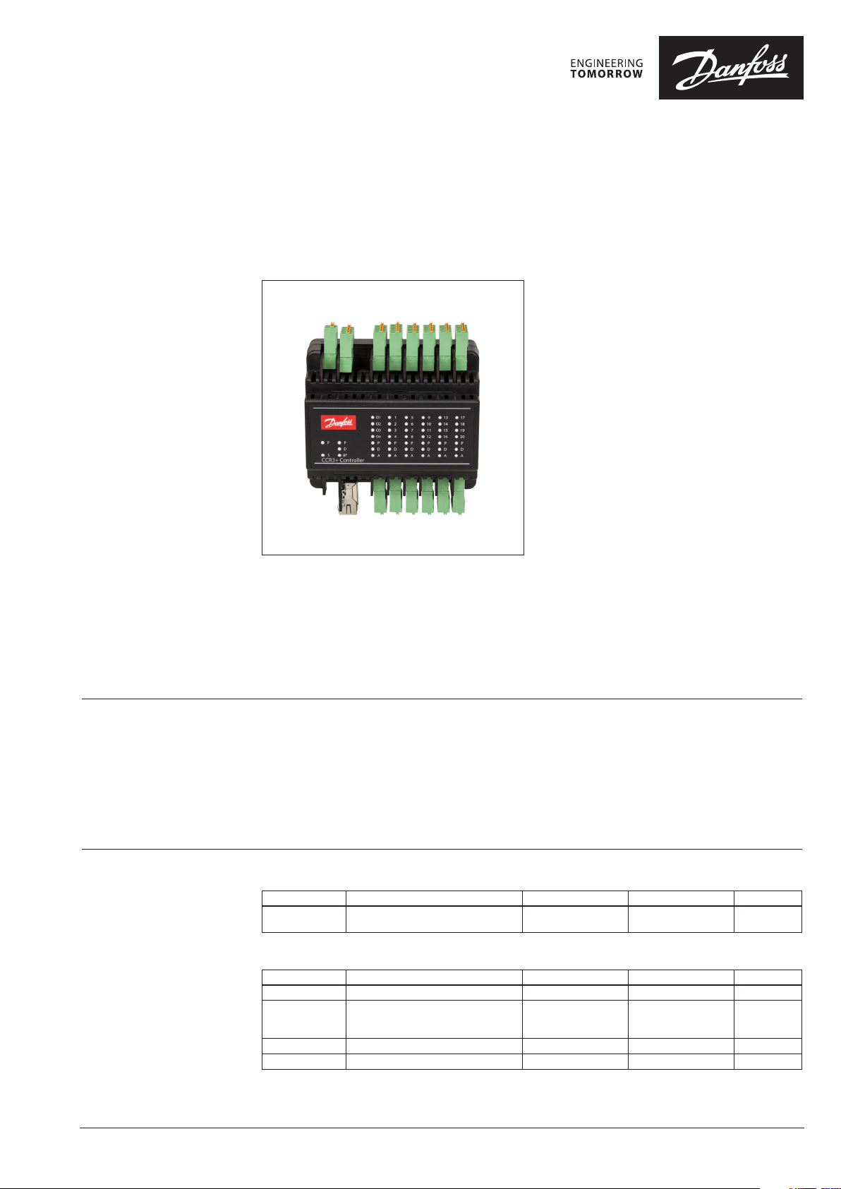
CCR3+ Controller
Return temperature controller & temperature registration
Description
The CCR3+ Controller is an electronic controller
for return temperature control in risers in
one-pipe heating system based on supply
temperature signal. With CCR3+ controller onepipe heating system becomes efficient variable
flow system with riser’s flow control based on
heat demand.
CCR3+ is dedicated to be used with AB-QM
automatic balancing & control valve equipped
with thermo actuators type TWA-Z (NO) and
remote temperature sensors type ESMC.
CCR3+ together with AB-QM and TWA-Z is
complete one-pipe electronic solution:
AB-QTE
Main data:
• Designed for AB-QM DN 10-32 mm
• Maximum number of controlled risers:
20 (extension +16 via Slave Unit)
• No distance limitation between risers (control
valves) and controller
• Pulse Wide Modulation (PWM) algorithm
• Return temperature (curve) adjustable in 9
points
• Individual riser setting possible
• Possible connection to BMS system
• Build in web server for access via mobile
devices or PC (readings, settings, datalogs,
etc)
• LED status indicators
• Flow control in risers based on heat demand
• Build in Web-Server App, Wi-Fi connection
and LAN port
Benefits
Ordering
• Improved room temperature control
• Eliminated overheating of the building
• Reduced heating cost with payback time less
than 4 years
• Remote control and access of all temperature
setting (no need to have direct access to
risers!)
Inclusive in the box: CCR3+ Controller, 1 pcs ESMC sensor
Typ e Designation Supply voltage Actuat or type/nos. Code No.
CCR3+ Controller
Accessory
Typ e Designation Voltage Comments Code No.
TWA-Z (NO) Thermal actuators 24 V 1.2 m. cable 08 2F1220
Set:
TWA-Z (NO) with
ESMC (PT 1000)
ESMC (PT 1000) Surface sensor - 2 meters cable 08 7N 0011
CCR+ Slave Unit System expansion (add 16 risers) 24 Vdc - 003Z3852
Return Temperature Controller &
Temperature Registration
Thermal actuators with surface sensor 24 V - 003Z0388
24 Vdc NO/20 003Z0396
© Danfoss | 2018.12
VD.GM.E1.02 | 1
Data sheet CCR3+ Controller
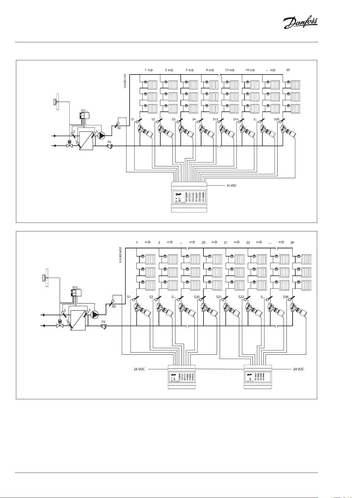
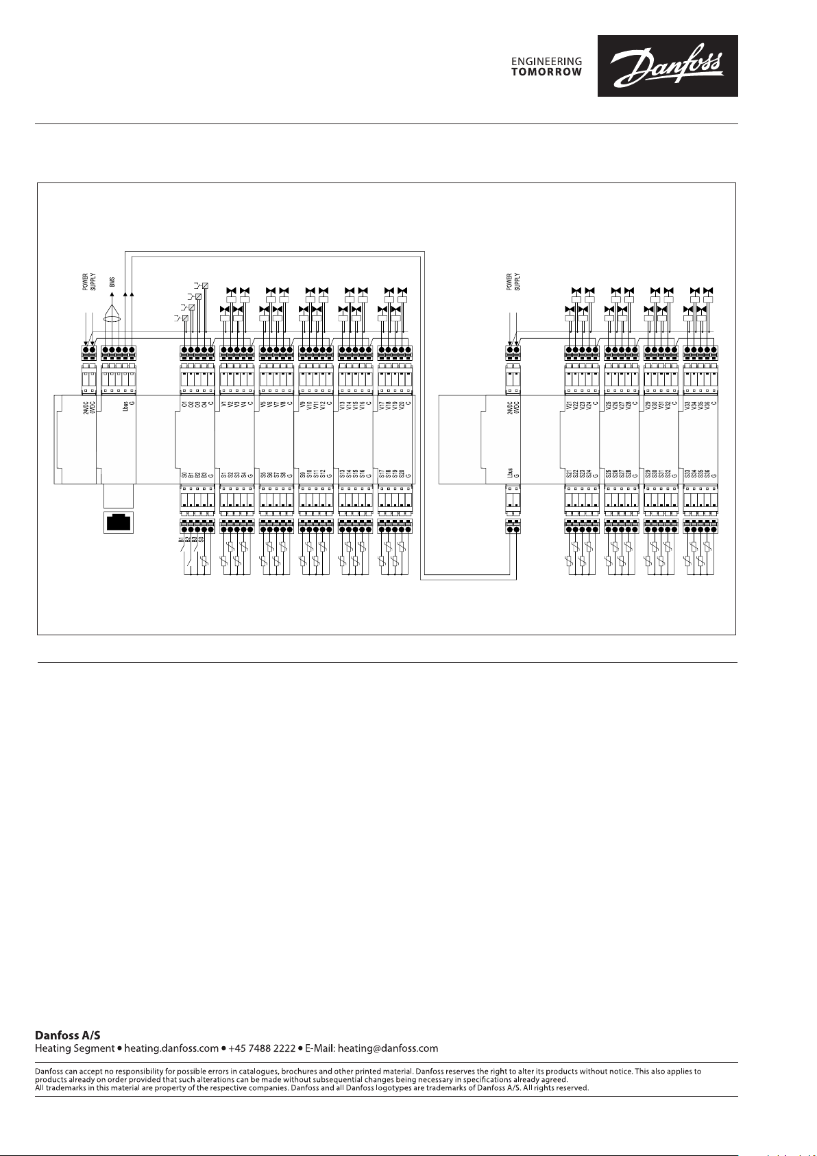
Applications
Fig. 1 CCR3+ Controller: scheme with 20 risers
Fig. 2 CCR3+ Controller: scheme with 36 risers
2 | © Danfoss | 2018.12
VD.GM.E1.02
Data sheet CCR3+ Controller
Applications (Continuous)
AB-QTE solution converts one-pipe heating
system - usually permanent flow system - into
efficient variable flow system.
This innovative solution dynamically controls the
flow in risers according to the load in risers by
return temperature control. Wide range of return
temperature setting (9 setting points) ensures
high efficiency of the system in whole range of
supply temperature from 35-90 °C.
In one-pipe systems flow in the risers is always
present even when all TRV’s are closed; water
flow through the by-pass which result in high
operating costs (heat losses, pumping costs,
overheating etc). TRV on the radiator controls
room temperature by controlling flow through
the radiator, while flow ratio between radiator
and by-pass is varying; however total flow in
risers remains permanent. At partial loads (some
TRV’s are closed) return water temperature in
risers increases, which results in overheating of
rooms due to very hot risers.
After the building is renovated heating system
becomes oversized since the heat losses of the
building decrease. As a result overheating issue
increases even more.
CCR3+ controller is part of AB-QTE solution
for one-pipe heating systems. It converts
one-pipe heating system (usually constant flow
system) into efficient variable flow system. This
innovative solution dynamically controls the
flow in the riser according to the load in risers by
return temperature control. Wide range of return
temperature setting (9 setting points) ensures
high efficiency of the system in whole range of
supply temperature from 35-90 °C.
In traditional one-pipe systems flow in the risers
is present even when all TRV’s are closed. Water
flows through the by-pass at all times. TRV on
the radiator controls room temperature by
controlling flow through the radiator, while flow
ratio between radiator and by-pass is varying.
Total flow in risers remains permanent though.
At partial loads (some TRV’s are closed) return
water temperature in risers increases. Result is
high operating costs: heat losses, pumping costs,
overheating, etc. In case building is renovated
overheating issue increases even more as
heating system becomes oversized.
AB-QTE concept solution:
• AB-QM mounted in the risers provides right
water balance in the risers at all system
condition. Every riser get designed flow and
each riser is independent from the rest of
installation.
• CCR3+ with temperature sensors and
actuators mounted on AB-QM controls flow
in risers through the return temperature
control. When return temperature increases
CCR3+ automatically detects this change and
reduces flow in risers according to set points
(lower load in risers – lower flow needed).
This results in improved room temperature
control and greatly reduced overheating of
the building.
Compared to self- acting solution (QT
thermostatic elements), AB-QTE solution
covers very wide temperature setting
range, as presented in Fig. 3. All points of
return temperature setting correspond to
supply temperature what allows automatic
adaptation to weather condition according
the rules: lower outside temperature , higher
supply temperature – except higher return
temperature, but all time optimized at any
supply parameter.
• Thus one-pipe system becomes energy
efficient variable flow system.
• AB-QTE solution is perfect from service,
monitoring and maintenance point of view.
The CCR2+ incorporates LED status indicator,
build in Web-Server App, Wi-Fi connection
and LAN port, which allow the user to
manually set, log and monitor measured
parameters from the system on smart device
or PC.
Danfoss AB-QTE solution for one-pipe
renovation system is a top end solution
where the first double curve system control
is proposed. First: on primary side , usually
in sub-station where weather compensatory
control supply temperature according out-door
temperature (based on weather compensator
curve). Second one: on secondary side where
return temperature curve is adjusted based
on supply water temperature. Lower outside
temperature requires higher supply temperature
which yields to also higher return temperature.
Key point: at all times optimized. Thus one-pipe
system becomes energy efficient variable flow
system.
The return temperature can be adjusted in
eight points, each correspondent to one flow
temperature.
The setting can be automatically applied for
all risers or using from menu additional setting
function return temperature can be modified
individually to each riser by:
Shift factor – allow to move up and down the
curve in each point, setting range ±10 °C.
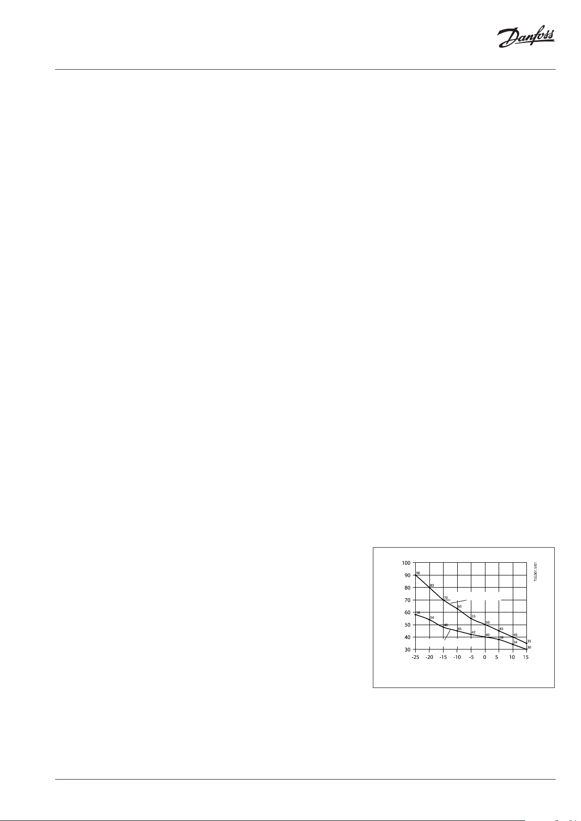
flow temperature
Temperature [°C]
return temperature
Outdoor temperature [°C]
Fig. 3 Return temperature curve graphs
VD.GM.E1.02
© Danfoss | 2018.12 | 3

Data sheet CCR3+ Controller
Technical data
Temperature sensor (S0, S1-S20 / S21-36) Pt1000, S0 – type ESMC/ESM11, S1-S20 / S21-36 – type ESMC
Temperature range (registration) –20 °C … +120 °C
Measuring accuracy +/- 0.5 K
Inputs: B1, B2 & B3 Free contact (5 V 1 mA)
Number of control valves (risers) 20 basic, additional 16 with system extension via CCR+ Slave Unit
Output signal to actuators 24 VDC max. 1 A
Alarm signal output 24 VDC ma x. 1 A
Relay output 0-24 VDC max. 1A
Type of memor y Build-In
Capacit y of memory 8 GB
Timer: Real time clock Built-in bat tery – powered for 10 years
- Wi-Fi (communication port only)
Communication interfaces
Default IP settings:
Ambient temperature
Transport temperature –10 … +60 °C
IP rating IP 20
Power supply 24 VDC
Power consumption (Controller only) 1)10 VA
Power consumption (Slave Unit only) 1)VA
Weight 0.3 kg
Installation DIN rail 35 mm
1)
To select pro per power transformer pl ease follow formula: 24 V 10VA (controller) + 7 VA*/per each ac tuator
- TPC/IP port (LAN cable connection)
- Modbus RS 485 RTU
- IP Modbus (L AN cable connection)
- Default L AN IP address (static): 192.168.1.100
- Default WiFi acess IP address (static): 192.168.1.10
- IP address mask: 255.255.255.0
- Gateway address: 192.168.1.1
- DNS address: 192.168.1.1
- CCR name: ccrplus
- Default password: admin1234
0 … +50 °C ( for CCR3+ only. The ambient temperature for actuators TWA-Z (NO)
should not be above 30 °C)
Settings Flow on AB-QM and temperature setting on
CCR3+ Controller need to be set to achieve best
performance and efficiency of one-pipe heating
system.
Recommended is a following 3 steps setting
procedure:
1. AB-QM setting
2. CCR3+ Controller setting
3. Follow up
There are two main reasons that influence onepipe system efficiency and therefore AB-QM and
CCR3+ setting:
1. renovation status of the building since
renovation is major reason for heating system
to become oversized, generally, after building
is renovated (wall & roof insulation, new
windows) existing heating system becomes
significantly oversized.
2. a dynamic nature of the heating load that is
changing unpredictably in he building due
to partial loads, internal gains and weather
conditions.
Notes:
• Install temperature sensor in front of AB-QM
and as close to last radiator in the riser/loop as
possible.
• After renovation, it is important to optimize
(reduce) flow temperature. Too high supply
water temperature can influence radiators
performance and result in oscillation of flow.
In addition, optimized flow temperature
improves efficiency of the one-pipe heating
system. This procedure should consider the worst
riser condition (big load, bad isolation etc).
• Ensure correct radiator a bypass flow setting
(typically around 25-35 %). If the resistance of
the radiator is much too high compared to the
bypass this may result in underflow through
radiator if the flow in riser/loop is reduced.
1. AB-QM setting
First it is necessary to set the AB-QM for required
flow before the actuators is mounted. Required
flow setting shall not be higher than calculated
design flow value Flow can be adjust according
standard AB-QM setting recommendation from
20 % to 100 %.
2. CCR3+ controller setting
Return temperature setting should be done
centrally on CCR3+ for all risers.
To simplify setting procedure it is required to
adjust only 9 return temperature points which
correspondent to supply temperature, e.g:
supply temp. 40 °C (required return temp. 38 °C),
supply temp. 45 °C (required return temp. 40 °C),
etc.
4 | © Danfoss | 2018.12
VD.GM.E1.02

Data sheet CCR3+ Controller
Settings (Continuous)
Mounting
These settings will apply for risers. Later, if
needed from menu we can choose option to
change setting individually for each riser. Setting
point can be moved up and down – according to
request. This option allows in easy way adapting
risers to individual demands.
For additional information about temperature
choosing for nominal condition including
Dynamic factor method please look in data sheet
for thermostatic actuators QT, page 6.
For simplification CCR3+ Controller offers default
setting (factory setting curve) that fits to typical
renovated system based on EN 15316 and ISO
13790.
Actuators:
more details on data sheet TWA-Z
Temperature sensors:
more details on data sheet PT1000 (ESM, ESMB,
ESMC, ESMT, ESMU)
Note: to compensate lo ng distance from sensor to CCR3+
controller (addi tional cable resistance can infl uence accuracy of
temperature m easuring), please use correctio n factors according
CCR3+ (see CCR3+ instructions). Cables shor ter than 10 m (0,75
mm2) and 15 (1,00 mm2) do not require any cor rection.
3. Follow up
Achieved energy efficiency of AB-QTE solution
depends on CCR3+ Controller setting. For
maximum results it is strongly recommended to
perform follow up on the installation during first
weeks of system operating. Easy access to setting
from one central place (where CCR3+ Controller
is installed) allows making any changes without
extra cost and efforts!
Temperature registration The CCR3+ Controller can measure temperature
with accuracy: ±0,5 °C.
Temperatures are measured by PT 1000
temperature sensors installed on the risers. If the
CCR3+ is used solely for recording temperatures,
it is not necessary to install any actuators on the
AB-QM valves.
Sampling time (data collection) intervals can
be adjusted using the control’s keypad from 1
minute.
Data are stored on internal memory. The data
collecting period depends strongly on and the
sampling interval.
Data are saved in *.csv format and can be
downloaded any time in Data menu.
The data can be visualised in spreadsheet and
graphs.
VD.GM.E1.02
© Danfoss | 2018.12 | 5

Data sheet CCR3+ Controller
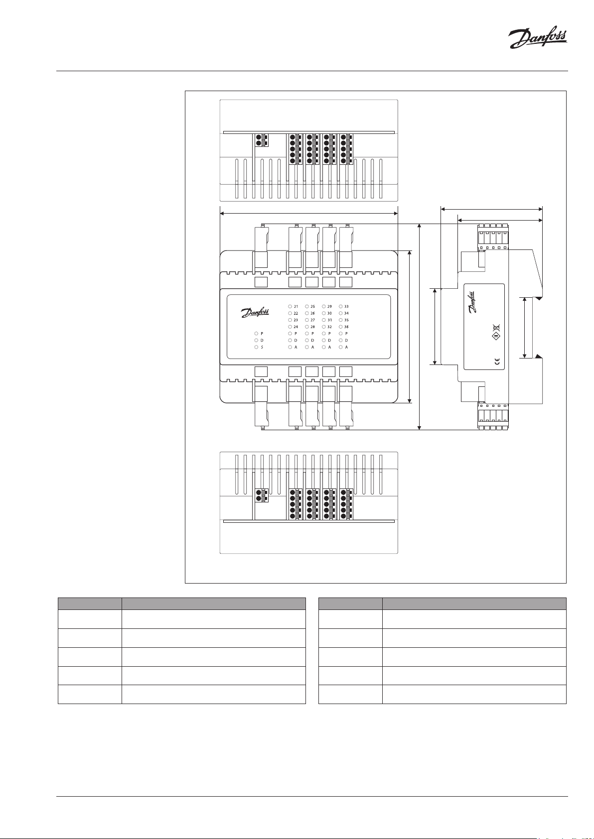
Wiring, Dimensions and
Installation
G
G
Lbus
24VDC
G
B
A
POWER
Master
LBus
0V
RS485
24VDC
CCR3+ Controller
TCP/IP
LAN
C
CCCCC
O4
V4
V8
V12
O3
V3
O2
O1
Module 0
V7
V2 V6 V10 V14 V18
V1
V5
Module 1
Module 2
V16
V11
V15
V9
V13
Module 3
Module 4
105 mm
C
O1-4
B1-3 S0
G
V1-4
S1-4
C
G
C
V5-8CV9-12
S5-8GS9-12
C
V13-16
S13-16
G
G
V20
V19
V17
Module 5
V17-20
S17-20
G
60 mm
50 mm
C
Danfoss A/S
MADE IN POLAND
6430 Nordborg, Denmark
90 mm
45 mm
122 mm
CCR3+
003Z0396
20171213V3.12
Return Temperatur e
Controller
RoHS
Supply 24VDC
36 mm
BOTOM
Connector/port Description
0V
24VDC
Lbus
RS485
C
O1,.. ,O4
C
V1-4
C
V5-8
C
V9 -12
0V – ground (-) power supply
24 V DC(+) power supply
G – ground Lbus port (for system expansion)
Lbus – Lbus por t (for system expansion)
G – ground (Modbus RS 485)
B – port B (Modbus RS 485)
A - port A (Modbus RS 485)
C – common port dedicated to outputs O1-O4
O1,.. O4 – defined outputs
C – common port dedicated to actuators V1-4
O1 - output: Alert Broken Sensor
O2 - output: Alert Low Temp
O3 - output: Alert High Temp
O4 - output: not in use
C – common port dedicated to actuators V5-8
V5. .V8 – outputs to ac tuators
C – common port dedicated to actuators V9-12
V9. .V12 – outputs to actuators
6 | © Danfoss | 2018.12
S5
S1
POWER
TCP/IP
Master
RJ45
B1
B2
B3
Module 0
S0
G
S6
S2
S7
S3
Module 1
Module 2
S8
S4
G
G
Fig. 4 Wiring scheme - CCR3+ Master Controller
Connector/port Description
C
V13 -16
C
V17-2 0
TC P/IP, LA N TCP/ IP port or IP Modbus port
B1-3, S0
G
S1-4
G
S5-8
G
S9 -12
G
S13 -16
G
S17-2 0
G
S9
S10
S11
Module 3
S12
G
S18
S14
S19
S15
Module 4
Module 5
S20
S16
G
G
C – common port dedicated to actuators V13-16
V13..V16 – outputs to actuators
C – common port dedicated to actuators V17-20
V17.. V20 – outputs to actuators
B1,B2, B3 defined inputs
S0 – temp. sensor
G – common ground dedicated to inputs/sensor
S1.. S4 – inputs from sensors
G – common ground dedicated to sensor S1-4
S5..S8 – inputs from sensors
G – common ground dedicated to sensors S5-8
S9. .S12 – inputs from sensors
G – common ground dedicated to sensors S9-12
S13.. S16 – inputs from sensors
G – common ground dedicated to sensors S13-16
S17. .S 20 – inputs from sensors
G – common ground dedicated to sensors S17-20
S17
S13
VD.GM.E1.02
Data sheet CCR3+ Controller
Wiring, Dimensions and
Installation (Continuous)
24VDC
Power
24VDC
CCR+ Slave
G
OV
G
LBus
C
V24
6
V23
V22
V21
Module
105 mm
C
V21-24
S21-24
G
C
V28
7
V27
V26
V25
Module
C
V25-28
S25-28
G
CC
V32
V36
V31
V35
V30 V34
V29
V33
Module 8
Module 9
C
C
V33-36
V29-32
S33-36
S29-32
G
G
90 mm
122 mm
45 mm
CCR+ Slave Unit
60 mm
50 mm
MADE IN POLAND
CCR+ Slave Unit
20171212VS.12
003Z3852
Danfoss A/S
6430 Nordborg, Denmark
36 mm
RoHS
Supply 24VDC
Connector/port Description
0V
24VDC
C
V21-24
C
V24 -28
C
V29-32
C
V30-36
0V – ground (-) power supply
24 VDC power supply
C – common port dedicated to actuators
V21..V 24 – outputs to ac tuators
C – common port dedicated to actuators
V24..V28 – outputs to actuators
C – common port dedicated to actuators
V29..V32 – outputs to actuators
C – common port dedicated to actuators
V33..V36 – outputs to actuators
VD.GM.E1.02
G
Lbus
Slave
0
S25
S21
S26
S22
S27
S23
Module 0
Module
S28
S24
G
GG
Fig. 5 Wiring scheme - CCR+ Slave Unit
1
2
S33
S29
S30
S34
S31
S35
Module
Module
S32
S36
G
Connector/port Description
Lbus G – ground Lbus port (for system expansion)
S21-24
G
S25 -28
G
S29-32
G
S33-36
G
Lbus – Lbus por t (for system expansion)
S21.. S24 – inputs from sensors
G – common ground dedicated to sensors
S25..S28 – inputs from sensors
G – common ground dedicated to sensors
S29.. S32 – inputs from sensors
G – common ground dedicated to sensors
S33..S36 – inputs from sensors
G – common ground dedicated to sensors
© Danfoss | 2018.12 | 7
Data sheet CCR3+ Controller
Wiring, Dimensions and
Installation (Continuous)
Power
Supply
Board
Master
Controller
Board
TCP/IP - LAN
WEB SERVER
BMS TCP/IP
ETHERNET
INTERNET
CCR3+ Master
Wiring diagram
Dened output O4
Dened output O3
Dened output O2
KO1
Def. output O4
24VDC
0V
Module 0
Empty
Input / Output
Socket
Board
Place
B1 - Def.input B1
B2 - Def.input B2
B3 - Def.input B3
KO3
KO2
S0 - main
KO4
sensor
PT1000
Input / Output
Actuators of risers’ valves V1...V20
Open collector outputs connect to 0V
V2V3V4V5V6V7V8V9V10
V1
Module 1
Module 2
Input / Output
Board
Board
Risers’ temperature sensors S1...S20
Type of sensor - PT1000
V11
Module 3
Input / Output
Board
V12
V14
V13
V15
Module 4
Input / Output
Board
V16
V18
V17
V19
Module 5
Input / Output
Board
CCR+ Slave
Wiring diagram
Actuators of risers’ valves V21...V36
Open collector outputs connect to 0V
V20
Empty
Socket
Place
24VDC
Controller
and Power
Slave
Supply
Board
24VDC
+ -
Empty
Socket
Place
V22
V24
V26
V21
V23
V25
Module 1
Input / Output
Module 2
Input / Output
Board
Board
Risers’ temperature sensors S21...S36
V28
V30
V32
V27
V29
V31
Module 3
Input / Output
Board
Type of sensor - PT1000
V34
V33
V35
Module 4
Input / Output
Board
V36
Fig. 6 Wiring sc heme CCR3+ Master Controller with CCR+ Slave
Tender text • One-pipe heating systems should have
electronic control of return temperature,
based on supply temperature signal.
• Temperature curve should be adjusted in
nine points from 35°C flow temperature up to
90°C.
• Control should base on: Return temperature
controller, automatic balancing & control
valve equipped with thermo actuators type
TWA-Z 24V (NO) and remote temperature
sensors type ESMC
• Controller allows return temperature control,
monitoring and registering temperatures
• Maximum number of controlled branches is
20, system can be expanded with slave unit
(+16)
• Controller allows connectivity with mobile
devices and personal computers
• Controller should have “Summer mode”
function (switchable in controller settings or
via BMS) to shut-off flow on control valves
when heating season is over.
• Controller allows connection to web
browser (HTLM) supported devices via Wi-Fi
communication port or LAN port
• Controller support BMS systems via RS 485
Modbus RTU and IP Modbus
• Unauthorized change of controller setting is
secured by password
• Controller should have Pulse Wide
Modulation (PWM) algorithm
• Build in pump protection function
• Controller can measure temperature with
accuracy: ±0,5 °C.
• Supply Voltage: 24V DC 50/60H
8 | © Danfoss | DHS-SRMT/SI | 2018.12
VD.GM.E1.02
 Loading...