

Page 1

Operating Guide
CCR3+ Controller
ENGLISH
DEUTSCH
LIETUVIŲ K.
CCR3+ Controller www.danfoss.com Page 2
Regler CCR3+ www.heating.danfoss.de Seite14
CCR3+ valdiklis
www.heating.danfoss.lt 22 psl.
© Danfoss | 2022.01
AQ29035882028101-010206 | 1
Page 2

CCR3+ Controller
Fig. 1 Installa tion with CCR3+ Controller (up to 20 risers/l oops)
Abb. 1 Install ation mit CCR3+ Regler (bis zu 20 Stränge/ Kreise)
1 pa v. Montavimas su CCR3+valdikliu (ne daug iau kaip 20 stovų / ciklų)
Fig. 2 Installa tion with CCR23 Controller (Master) and CCR+ Slave Unit (mor e that 20 risers)
Abb. 2 Installation mit CCR3+ Regler (Führungsregler) und CCR+ Nebenregler (mehr als 20 Stränge)
2 pa v. Montavimas su CCR23valdikliu ir CCR+prapl ėtimo moduliu(daugiau kai p 20 vamzdyno stovų)
2 | © Danfoss | 2022.01
AQ29035882028101-010206
Page 3

CCR3+ Controller
G
G
Lbus
24VDC
G
B
A
POWER
Master
LBus
0V
RS485
24VDC
CCR3+ Controller
TCP/IP
LAN
C
CCCCC
O4
V4
V8
V12
O3
V3
O2
O1
Module 0
V7
V2 V6 V10 V14 V18
V1
V5
Module 1
Module 2
V16
V11
V15
V9
V13
Module 3
Module 4
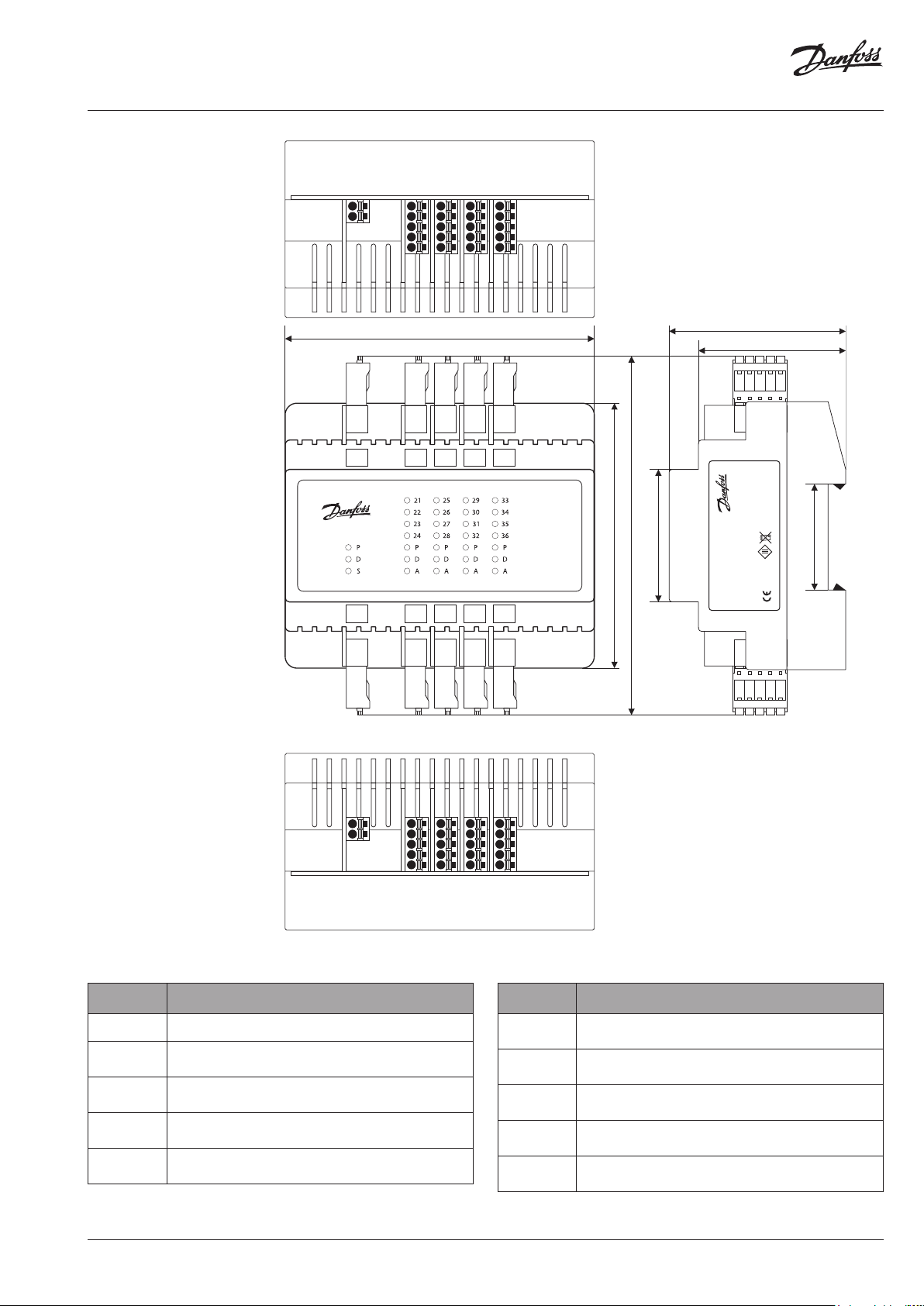
105 mm
C
O1-4
B1-3 S0
G
V1-4
S1-4
C
G
C
V5-8CV9-12
S5-8GS9-12
C
V13-16
S13-16
G
G
V20
V19
V17
Module 5
C
V17-20
S17-20
G
90 mm
122 mm
45 mm
Return Temperatur e
60 mm
MADE IN POLAND
CCR3+
Controller
50 mm
003Z0396
Supply 24VDC
20171213V3.12
Danfoss A/S
6430 Nordborg, Denmark
RoHS
36 mm
BOTOM
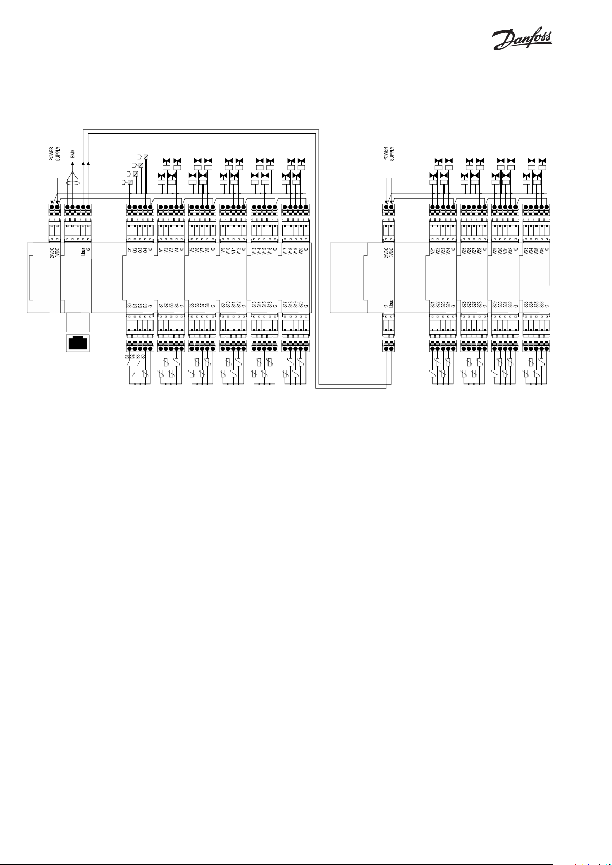
Fig. 3 Wiring sc heme - CCR3+ Master Controller
Abb. 3 Schaltbild – CCR3+ Führungsregler
3 pa v. Laidų schema – CCR3+valdiklis
Connector/port
Stecker/Klemme
Jungti s/ lizdas
0V
24VDC
Lbus
RS485
C
O1,.. ,O4
C
V1-4
C
V5-8
C
V9 -12
Description / Beschreibung / Aprašymas
0V – ground (-) powe r supply / 0V – Masse (-) Span nungsversorgu ng /
0 V – įžeminimas (-) maitinimas
24 VD C(+) power supp ly / 24 V DC(+) Spannungsversorgung /
24 V pastovioji srovė (+) maitinimas
G – ground Lbu s port (for syste m expansion) / G – Mass e Lbus-Anschluss (f ür
Systemerweiterung) / G –Lbus magistralė sįžeminimo jungt is (sistemai prapl ėsti)
Lbus – Lbus port (fo r system expans ion) / Lbus – Lbus-Anschluss (f ür Systemerwei terung) /
Lbus – Lbus magistr alėsjungtis(siste mai praplėsti)
G – ground (Mod bus RS 485) / G – Masse (Mo dbus RS 485) / G – įžemini mas (Modbus RS 485)
B – port B (Mod bus RS 485) / B – Anschlus s B (Modbus RS 485) / B – B jun gtis (Modbus RS 48 5)
A – port A (Mod bus RS 485) / A – Anschlus s A (Modbus RS 485) / A – A jung tis (Modbus RS 48 5)
C – common por t dedicated to ou tputs O1-O4 / C – geme insamer Anschlu ss für Ausgän ge
O1–O4 / C – bendra j ungtis skirt aišėjimams O1-O4
O1 – output: Ale rt Broken Sen sor / O1 – Ausgang: Warnu ng gebrochen er Sensor / O1 – išėjimas:
Pažeisto jutiklio įspėjimo signalas
O2 – output: Ale rt Low Temp / O2 – Ausgang: Warn ung niedrige Temp. / O2 - iš ėjimas: Per žemos
temperatūros įspėjimo signalas
O3 – output: Ale rt High Temp / O3 – Ausgang: Wa rnung hohe Temp. / O3 - išėji mas: Per aukšto s
temperatūros įspėjimo signalas
O4 – output: n ot in use / O4 – Ausgang: Ni cht verwende t / O4 - išėjimas: nenaudojamas
C – common por t dedicated to ac tuators V1-4 / C – gemeinsamer Anschluss für Stellantriebe
V1–4 / C – bendra p avaroms skirt a jungtis V1-4
V1..V4 – out puts to actuator s / V1..V4 – Ausgänge z u Stellantrieben / V 1..V4 – išėjimai
į pavaras
C – common por t dedicated to ac tuators V5- 8 / C – gemeinsamer Anschluss für Stellantriebe
V5–8 / C – ben dra pavaroms skir tajungtis V5- 8
V5..V 8 – outputs to ac tuators / V5. .V8 – Ausgänge zu St ellantrieben / V 5..V8 – išėj imai į
pavaras
C – common por t dedicated to ac tuators V9-12 / C – gemeins amer Anschluss f ür
Stellantriebe V9–12 / C – bendra jungti s, skirta pavar oms V9-12
V9. .V12 – outputs t o actuators / V9 ..V12 – Ausg änge zu Stellantri eben / V9.. V12 – išėjimai
į pavaras
AQ29035882028101-010206
POWER
TCP/IP
Master
RJ45
B1
B2
B3
Module 0
S0
G
S5
S1
S6
S2
S7
S3
Module 1
Module 2
S8
S4
G
G
Connector/port
Stecker/Klemme
Jungti s/ lizdas
C
V13-1 6
C
V17-2 0
TC P/I P, L AN
B1-3, S0
G
S1-4
G
S5-8
G
S9 -12
G
S13-16
G
S17-20
G
S9
S10
S11
Module 3
S12
G
S18
S14
S19
S15
Module 4
Module 5
S20
S16
G
G
Description / Beschreibung / Aprašymas
C – common por t dedicated to ac tuators V13-16 / C – gemeinsame r Anschluss fü r
Stellantri ebe V13–16 / C – bendra j ungtis, skirt a pavaroms V13-16
V13..V16 – outputs to ac tuators / V13..V16 – Ausgänge zu Ste llantrieben / V13..V16 –
išėjimai į pav aras
C – common por t dedicated to ac tuators V17-20 / C – gemeinsame r Anschluss für
Stellantri ebe V17–20 / C – bendra ju ngtis, skirt a pavaroms V17-20
V17. .V2 0 – outp uts to actuators / V 17.. V20 – Ausgänge zu Ste llantrieben / V 17.. V20 –
išėjimai į pav aras
TCP/I P port or IP M odbus port / T CP/IP -Anschluss oder IP Modbus-Anschluss / TCP/IP jungtis
arba IP Mod bus jungtis
B1,B2, B3 defined inputs / B1,B2, B3 definierte Eingänge / B1,B2, B3 numatytieji įėjimai
S0 – temp. sensor / S0 – Temp.-S ensor / S0 – temp. jutik lis
G – common grou nd dedicated to in puts/sensor / G – gem einsame Masse fü r Eingänge/
Sensor / G – bendras įžeminimas, skirt as įėjimams / jutikliams
S1..S 4 – inputs fro m sensors / S1.. S4 – Eingänge v on Sensoren / S1.. S4 – įėjimai i š jutiklių
G – common grou nd dedicated to se nsor S1-4 / G – gemeinsam e Masse
für Sensor en S1–4 / G – bendras įžeminimas, skirtas jutikliams S1-4
S5..S8 – inpu ts from sensors / S5 ..S8 – Eingänge vo n Sensoren / S5..S 8 – įėjimai iš jutikli ų
G – common grou nd dedicated to se nsors S5-8 / G – gem einsame Masse f ür Sensoren S5– 8 /
G – bendras įžeminimas, skirtas jutikliams S5-8
S9. .S12 – input s from sensors / S 9..S 12 – Eingänge von S ensoren / S9. .S12 – įėji mai iš jutiklių
G – common groun d dedicated to se nsors S9-12 / G – gemeinsame M asse für Sensor en S9–12 /
G – bendras įžeminimas, skirtas jutikliams S9-12
S13.. S16 – inputs from se nsors / S13.. S16 – Eingänge von Se nsoren / S13.. S16 – įėjimai
iš jutiklių
G – common grou nd dedicated to se nsors S13-16 / G – gemeinsame Masse f ür Sensoren
S13–16 / G – bendras įžeminimas, skirtas jutikliams S13-16
S17. .S 20 – inp uts from sens ors / S17. .S 20 – Ein gänge von Senso ren / S17. .S 20 – įėjim ai iš jutiklių
G – common grou nd dedicated to se nsors S17-20 / G – gemeinsame Masse f ür Sensoren
S17–20 / G – bendras įžeminimas, skirtas jutikliams S17-20
S17
S13
© Danfoss | 2022.01 | 3
Page 4
CCR3+ Controller
B3 - Def.input B3
PT1000
Power
Supply
Board
Master
Controller
Board
TCP/IP - LAN
WEB SERVER
BMS TCP/IP
ETHERNET
INTERNET
Dened output O4
Dened output O3
Dened output O2
Def. output O4
24VDC
0V
Empty
Socket
Place
B1 - Def.input B1
B2 - Def.input B2
CCR3+ Master
Wiring diagram
Actuators of risers’ valves V1...V20
KO4
KO3
KO2
KO1
Module 0
Input / Output
Board
S0 - main
sensor
Input / Output
Open collector outputs connect to 0V
V2V3V4V5V6V7V8V9V10
V1
Module 1
Board
Module 2
Input / Output
Board
Risers’ temperature sensors S1...S20
V12
V11
Module 3
Input / Output
Board
Type of sensor - PT1000
V14
V16
V13
V15
Module 4
Input / Output
Board
V18
V20
V17
V19
Module 5
Input / Output
Board
24VDC
Empty
Socket
Place
LBus 2x0.5mm2
(L=max. 100m)
24VDC
Slave
Controller
and Power
Supply
Board
CCR+ Slave
Wiring diagram
Actuators of risers’ valves V21...V36
Open collector outputs connect to 0V
V22
V24
V26
V28
V30
V32
V34
+ -
Empty
Socket
Place
V21
V23
Module 1
Input / Output
Board
V25
V27
V29
V31
Module 2
Input / Output
Risers’ temperature sensors S21...S36
Module 3
Input / Output
Board
Board
Type of sensor - PT1000
V33
V35
Module 4
Input / Output
Board
V36
Fig. 4 Wiring sc heme CCR3+ Master Controller with CCR+ Slave
Abb. 4 Schaltbild CCR3+ Führungsregler mit CCR+ Nebenregler
4 pav. Laidų jung imo schema - CCR3+valdiklio su CCR+ praplėtim o moduliu
4 | © Danfoss | 2022.01
AQ29035882028101-010206
Page 5
CCR3+ Controller
24VDC
Power
24VDC
CCR+ Slave
LBus
G
OV
C
V24
6
V23
V22
V21
Module
105 mm
C
V21-24
C
V28
7
V27
V26
V25
Module
C
V25-28
CC
V32
V36
V31
V35
V30 V34
V29
V33
Module 8
Module 9
C
C
V33-36
V29-32
90 mm
122 mm
45 mm
60 mm
50 mm
MADE IN POLAND
Danfoss A/S
6430 Nordborg, Denmark
36 mm
RoHS
CCR+ Slave Unit
20171212VS.12
003Z3852
Supply 24VDC
G
S21-24
G
G
G
G
S33-36
S29-32
S25-28
CCR+ Slave Unit
Fig. 5 Wiring scheme - CCR+ Slave Unit
Abb. 5 Schaltbild – CCR+ Nebenregler
5 pa v. Laidų schema – CCR+ praplėtimo modulis
Connector/port
Stecker/Klemme
Jungti s / lizdas
0V
24VDC
C
V21-24
C
V24 -28
C
V29-32
C
V33-36
Description / Beschreibung / Aprašymas
0V – ground (-) powe r supply / 0V – Masse (-) Span nungsversorgu ng / 0 V – įžeminimas
(-) maitinimas
24 VDC power s upply / 24 V DC Spannungsversorgung / 24 V pastovioji srovė maitinimas
C – common por t dedicated to ac tuators / C – gemei nsamer Anschlus s für Stellantrieb e /
C – bendra pavaroms skirta jungtis
V21..V2 4 – outputs to ac tuators / V21..V 24 – Ausgänge zu St ellantrieben / V 21..V24 –
išėjimai į pav aras
C – common por t dedicated to ac tuators / C – gemei nsamer Anschlus s für Stellantrieb e /
C – bendra pavaroms skirta jungtis
V24..V28 – outputs to act uators / V24..V28 – Ausgänge zu Stella ntrieben / V24..V28 –
išėjimai į pav aras
C – common por t dedicated to ac tuators / C – gemei nsamer Anschlus s für Stellantrieb e /
C – bendra pavaroms skirta jungtis
V29. .V32 – outpu ts to actuators / V 29..V3 2 – Ausgänge zu Stel lantrieben / V2 9..V32 –
išėjimai į pav aras
C – common port dedicated to actuators / C – gemeinsamer Anschluss für Stellantriebe /
C – bendra pavaroms skirta jungtis
V33..V36 – out puts to actu ators / V33..V36 – Au sgänge zu Ste llantrie ben / V33..V36 –
išėjimai į pavaras
AQ29035882028101-010206
Slave
G
Lbus
1
S29
S30
S31
Module
S32
2
S33
S34
S35
Module
S36
G
Connector/port
Stecker/Klemme
Jungti s / lizdas
Lbus
S21-24
G
S25-2 8
G
S29-32
G
S33-36
G
0
S25
S21
S26
S22
S27
S23
Module 0
Module
S28
S24
G
GG
Description / Beschreibung / Aprašymas
G – ground Lbu s port (for syste m expansion) / G – Mass e Lbus-Anschluss (f ür
Systemerweiterung) / G –Lbus magistralė sįžeminimo jungt is (sistemai prapl ėsti)
Lbus – Lbus port (fo r system expans ion) / Lbus – Lbus-Anschluss
(für Systemerweiterung) / Lbus – Lbus magis tralėsjungtis(sis temai praplės ti)
S21.. S24 – inputs fr om sensors / S21. .S24 – Eing änge von Sensore n / S21..S24 – įėjimai
iš jutiklių
G – common grou nd dedicated to se nsors / G – gemeins ame Masse für Sens oren /
G – bendras jutikliams skirtas įžeminimas
S25..S28 – input s from sensors / S25.. S28 – Eingänge von Se nsoren / S25..S28 – įėjima i
iš jutiklių
G – common grou nd dedicated to se nsors / G – gemeins ame Masse für Sens oren /
G – bendras jutikliams skirtas įžeminimas
S29..S32 – inputs from sen sors / S29..S32 – Ei ngänge von Senso ren / S29..S32 – įėji mai
iš jutiklių
G – common grou nd dedicated to se nsors / G – gemeins ame Masse für Sens oren /
G – bendras jutikliams skirtas įžeminimas
S33..S36 – input s from sensors / S33. .S36 – Eingänge von S ensoren / S33..S36 – įėji mai
iš jutiklių
G – common grou nd dedicated to se nsors / G – gemeins ame Masse für Sens oren /
G – bendras jutikliams skirtas įžeminimas
© Danfoss | 2022.01 | 5
Page 6

CCR3+ Controller
LANGUAGE
ENGLISH
1. Product description
2. Application
The CCR3+ Controller is a controller used to
control return temperature in one pipe heating
systems with functions such as temperature
registration and monitoring riser temperature.
The controller is connected to thermo actuators
type TWA-Z (NO) and remote temperature
sensors PT1000, type ESMC installed on each
riser.
3. Technical data
CCR3+ controller is part of AB-QTE solution
for one-pipe heating systems. It converts
one-pipe heating system (usually constant ow
system) into ecient variable ow system. This
innovative solution dynamically controls the
ow in the riser according to the load in risers by
return temperature control. There are few basic
rules to be followed, even more valid in case of
renovation:
• Optimize ow temperature that is driven by
substation control (too high ow temperature
can inuence eciency of rst radiators in the
riser/loop and result in oscillation of ow).
• Optimize return temperature that is driven
by CCR3+ (too high return temperature can
result in lower energy eciency).
• Install temperature sensor in front of AB-QM
as close to last radiator in the riser/loop as
possible.
• Set AB-QM according to the required heat
load of the riser/loop.
• Ensure correct radiator bypass ow setting
(typically around 25-35 %). If the resistance of
the radiator is much too high compared to the
bypass this may result in underow through
radiator if the ow in riser/loop is reduced.
Temperature sensor (S0, S1-S20 / S21-36) Pt1000, S0 – type ESMC/ESM11, S1-S20 / S21-36 – type ESMC
Temperature range (registration) –20 °C … +120 °C
Measuring accuracy +/- 0.5 K
Inputs: B1, B2 & B3 Free contact (5 V 1 mA)
Number of control valves (risers) 20 basic, additional 16 with system ex tension via CCR+ Slave Unit
Output signal to actuators 24 VDC max. 1 A
Alarm signal output 24 VDC max. 1 A
Relay output 0-24 VDC max. 1A
Type of memory Build-In
Capacity of memor y 8 GB
Timer: Real time clock Built-in bat tery – powered for 10 years
- Wi-Fi (communication p ort only)
Communication interfaces
Default IP settings:
Ambient temperature
Transport temperature –10 … +60 °C
IP rating IP 20
Power supply 24 VDC
Power consumption (Controller only) 1)10 VA
Power consumption (Slave Unit only) 1)3 VA
Weight 0.3 kg
Installation DIN rail 35 mm
1)
To select proper p ower transformer please f ollow formula: 24 V 10 VA (controller) + 7 VA*/pe r each actuator
- TPC/IP port (LAN cable connection)
- Modbus RS 485 RTU
- IP Modbus (L AN cable connection)
- Default L AN IP address (static): 192.168.1.100
- Default WiFi acess IP address (static): 192.168.1.10
- IP address mask: 255.255.255.0
- Gateway address: 192.168.1.1
- DNS address: 192.168.1.1
- CCR name: ccrplus
- Default password: admin1234
0 … +50 °C ( for CCR3+ only. The ambient temperature for actuators TWA-Z (NO)
should not be above 30 °C)
Following above rules will ensure optimal
control performance of CCR3+ as well as energy
eciency and reliability of heating systems.
For further application insights please contact
Danfoss representative.
6 | © Danfoss | 2022.01
AQ29035882028101-010206
Page 7
CCR3+ Controller
ENGLISH
4. Installation
5. Switching the control on
For easy access the CCR3+ Controller is installed in
the
technical box on DIN rail 35mm. Box with
DIN rail should be mounted in the wall (substation or boiler
room) as close as possible to the
heat source. DIN rail and box are not included. It is
recommended to install
the standard 24 VDC
transformer in the same box as CCR3+ (not
supplied).
Before switching the controller on for the rst
time, disconnect all cables and connect a 24VDC
source to the disconnected power plug. Use a
voltmeter to measure the voltage on the power
cable plug before it is connected to the
controller.
If the voltage is correct:
1. Read the instructions before you operate the
controller
2. Disconnect all cables
3. Connect the power to the transformer (not
connected to CCR3+)
4. Turn the power to the transformer on
5. Veried currency – 24 VDC
6. Connect the cable from the transformer to the
CCR3+ Controller input
The transformer power depends on numbers of
actuators (number of risers in heating
installation). To select proper power transformer
please follow formula: 24 V 10VA (controller) + 7
VA*/per each actuator.
Example (building with 20 risers):
10VA (for controller) + 7 VA x 20 actuators = 150 V
The LED diodes on device should blink at
start-up.
Before any plugs are connected to the
controllers, input and output connectors:
1. Set all parameters on the controller
2.
Make sure that there is no external voltage on
the
temperature sensor plugs
3. Make sure that the voltage on the relay
contacts is not too high (max. 24 VDC)
6. Switching on
7. Types of Logins and Access
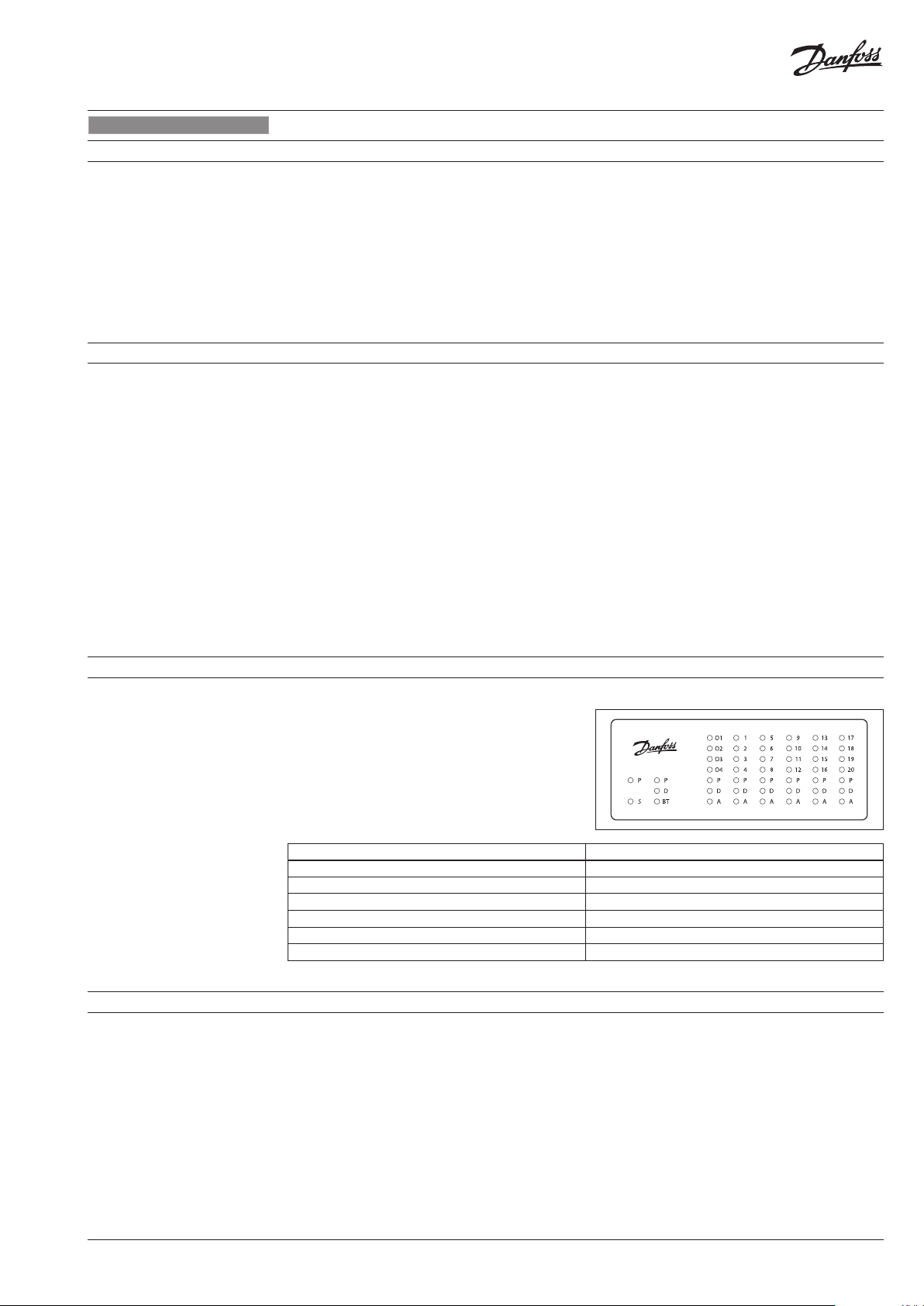
When controller is connected to power, LED
indicator start to blink. The meaning of LED
status is:
LED Description
P (orange) – Power inside controller (+5V) Lights when DDC PCB is power on
D (white) – Data transfer indicator for LAN Blink when DDC is communicating by TCP/IP
S (orange) - Input power indicator (24VDC) Lights when power supply PCB is working
BT (blue)– Basic transmission indicator for Wi-Fi Blink when DDC is communicating by WiFi
A (red) – Alert status on I/O module LED lights when/if: to low temp., broken sensor
O1..4 ; 1-20 (green)– Digital Output Status Lights when Output is closed to 0V
Controller has a built in WEB Server App to
communicate with all devices with html
browsers via following communication
interfaces:
• Wi-Fi communication port
• LAN cable connection (TCP/IP port)
AQ29035882028101-010206
© Danfoss | 2022.01 | 7
Page 8
CCR3+ Controller
ENGLISH
8. Wi-Fi settings (no cable needed - recommended for all types of devices)
1. Switch on Wi-Fi
2. Scan for Wireless Network Connection
3. Select CCR WI-Fi network
4. Enter password (default is »admin1234«)
5. Connect
9. Local Network settings (only for LAN cable connection with PC)
1. Enter »Local Network settings«
2. Go to »Properties« -> »Internet Protocol
Version 4 (TCP/IPv4)
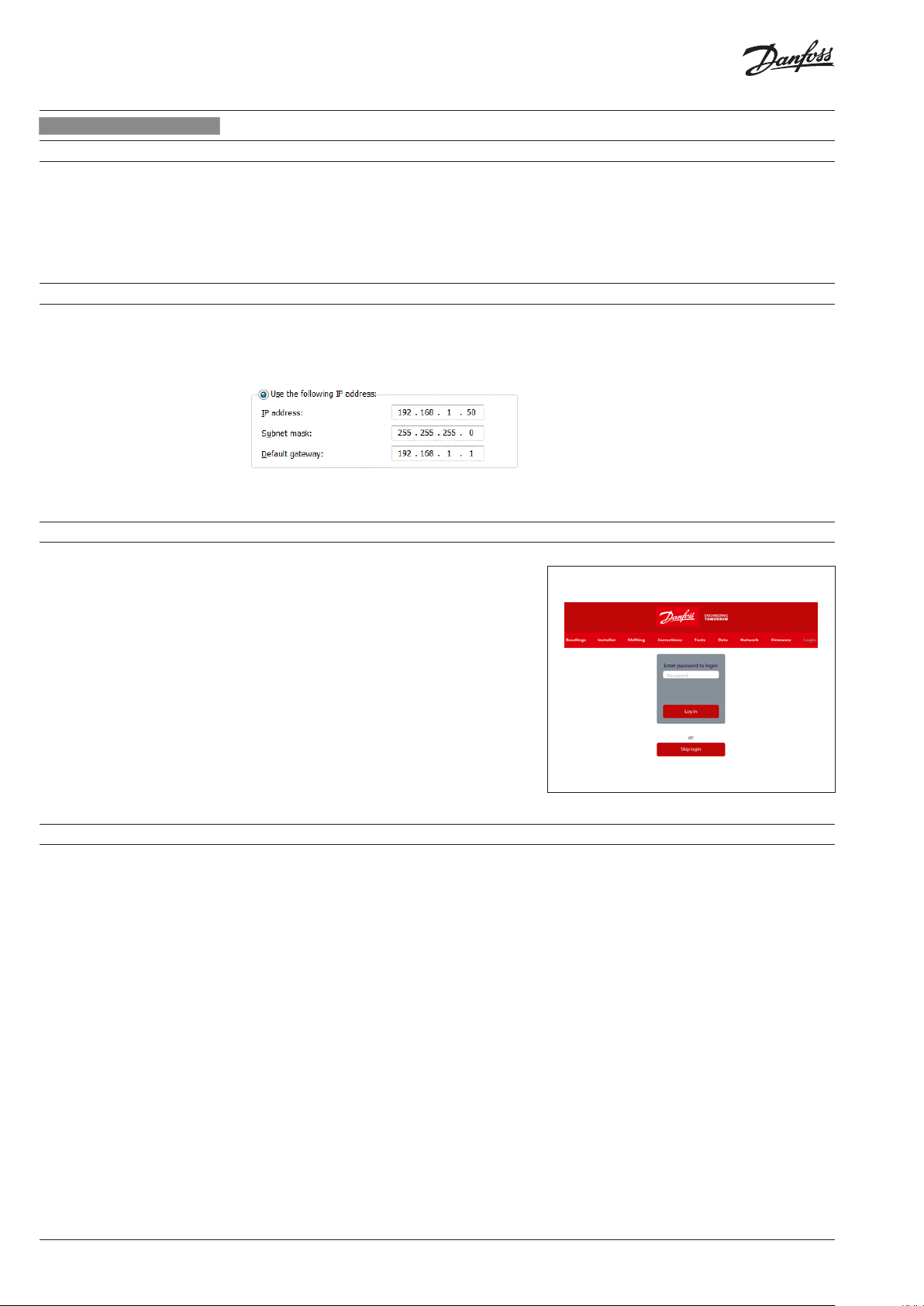
3. Congure IP address:
4. Conrm with »OK« and close menu in PC.
10. Run CCR3+ application
Launch your browser from a computer or
wireless device that is connected to the CCR3+.
Tap the IP address into web browser window:
1. Wi-FI access: Type 192.168.1.10 into Web
Browser
2. LAN connection: Type 192.168.1.100 into Web
Browser
CCR3+ application will open.
For 1st login enter password »admin1234«
Important: Change of password to secure any
unauthorized interaction from 3rd parties.
Note: You can Skip login for access to data only
in CCR3+ (reading, overview only).
11. CCR3+ Dashboard (Web App Screen)
When the setup and is complete, the reading
display will be shown on the screen.
The CCR3+ App screen has a dashboard that
oer plenty of status overview, basic and
advanced settings. The manufacturer reserves
the right to change Firmware in production to
improve handling and functionality. An up - to
- date list of settings for the given rmware is
available on the Danfoss website.
New settings can automatically upgrade
according to guidelines in instruction.
• Readings: Informations about basic settings,
device status, current time and date, storage
capacity
• Installer: Advanced and service settings
• Shifting: Shift return temperature
• Corrections: Temperature sensor calibration
settings
• Tes ts: Device outputs testing tool
• Data: Access to Data log le
• Network: BMS and IP/TPC settings
• Firmware: Firmware upgrade tool
• Login: Login option
8 | © Danfoss | 2022.01
AQ29035882028101-010206
Page 9

CCR3+ Controller
ENGLISH
11. CCR3+ DASHBOARD
(Web App Screen)
(continuous)
READINGS MENU:
No. Name Description
Output status (Dened output O1..O4)
1 O1..O 4
2 B1..B3
3 RT Clock
4 S0-main temp.
5 Ret.Set.Temp
6 Alerts
7 Riser
8 Valve output
9 Valve [%] … ..% – valve open ratio – percentage of lling the PWM func tion (0 … 100 % in 10 % steps)
Temperature
10
[°C]
11 Set. Temp.[°C]
12 Alerts
Open - no alarm or break alarm circuit
Closed – shortcut to ground in alarm circuit
See Outputs settings in Installer Menu.
Input status
Open - input Bx open
Closed – input B1 close to G
Free contact relay (not used in CCR3+ process, only for monitoring in BMS). Binary inputs or P T10 00
sens or (5V, 1mA).
The Real Time clock , show current time, date, day of the week.
Data used in archive le.
S0 – value of (°C) supply temperature. The same readings apply to sensors S1 … S20.
Open - no sensor or break sensor circuit
Closed – shortcut to ground in sensor circuit
Fault – temp. values exeed Fault temp. max or is bellow Fault temp. max (correspondent to Fault temp.
settings in Installer Menu)
Information about setting return temperature correspondent to current ow temperature, in °C degree.
Required range set in points in the Installer Menu. Func tion used for temperature alarm output.
Set. Temperature is = Return Set. Temperature +/- Shift T. Set.
General information about CCR3+ status
OK – system is running without alarms
Aler t (red) – system has alarms
Riser St atus (sensors: S1-S36; valves: V1-V36)
Number of risers (look to: Advanced Menu)
Riser statuses are indicated with color.
OK – riser status is OK
High (red) - if temp. on Sx sensor is higher then Ret.Set.Temp
Low (bl ue) - if temp. on Sx sensor is lower then Ret.Set.Temp.
Open (yellow) - no sensor or break sensor circuit
Closed (grey) - shortcut to ground in sensor circuit
N/A (white) - non relevant (non selected) risers
Status of valve: V1 … V36
1 – open, valve output closed to C (powered up), (taking PWM into account).
0 – valve closed, valve output closed to C (powered down), (taking PWM into account).
Valve is 1-Open if: PWM min < Valve % <PWM max
Temperature readings in riser
Open - no sensor or break sensor circuit
Closed – shortcut to ground in sensor circuit
Information about return temperature correspondent to Ret.Set.Temp and Shift setting (correspondent
to Shift T.Set in Shifting Menu)
Set. Temperature is = Return Set.
Temperature +/- Shif t T. Set.
Temperatures status (same color as described in pos. “Riser status” ):
Riser RX – riser status information:
OK – riser status is OK
High (red) - if temp. on Sx sensor is higher then Ret.Set.Temp
Low (bl ue) - if temp. on Sx sensor is lower then Ret.Set.Temp.
Open (yellow) - no sensor or break sensor circuit
Closed (grey) - shortcut to ground in sensor circuit
N/A (white) - non relevant (non congurated) risers
AQ29035882028101-010206
INSTALLER MENU:
No. Name Description
13 TRet(35)
14 TRet(4 0)
15 TRet(45)
16 TRet(50)
17 TRet(55)
18 TRet(63)
19 TRet(70)
20 TRet(80)
Required return temperature for measure supply temperature: 35°C
Factory setting: 30°C
Required return temperature for measure supply temperature: 40°C
Factory setting: 35°C
Required return temperature for measure supply temperature: 45°C
Factory setting: 38°C
Required return temperature for measure supply temperature: 50°C
Factory setting: 40°C
Required return temperature for measure supply temperature: 55°C
Factory setting: 42°C
Required return temperature for measure supply temperature: 63°C
Factory setting: 45°C
Required return temperature for measure supply temperature: 70°C
Factory setting: 48°C
Required return temperature for measure supply temperature: 80°C
Factory setting: 54°C
© Danfoss | 2022.01 | 9
Page 10

CCR3+ Controller
LANGUAGE
ENGLISH
11. CCR3+ DASHBOARD
(Web App Screen)
(continuous)
No. Name Description
21 TR et(90)
22 Integration time
23 Proportional factor
24 Dif. T ime
25 PWM interval
26 PWM min.
27 PWM max.
28 Fault temp min.
29 Risers Nr
30 Current time
31 Current date
32 Alarm Delay
33 Alarm di.temp.+/-
34 Alarm Relay Type
35 Archive Frequency
36 Output O1
37 Output O2
38 Output O3
39 Output O4 N/A: Selected Output O4 not in use
40 Pump protection Factory setting: YES
41 Summer mode
42 Set Settings Click »Set Set tings« to conrm changes.
43 Load set tings 1 Load settings from memory 1.
44 Load settings 2 Load settings from memory 2.
45 Save settings 1 Save settings into memory 1.
46 Save settings 2 Save settings from memor y 2.
Required return temperature for measure supply temperature: 90°C
Factory setting: 58°C
Integration time of the control signal (depend of actuators type). The shorter time, quicker
temperature changes (no stable regulation). The longer time slower reaction for temperature
change (stable regulation).
Factory setting: 6 sec (for dedicated T WA-Z (NO) actuators); setting range 1-100
Control gain of control signal (depend on actuators type). The higher gain control the bigger
valves reac tion (no stable regulation). The lower gain control weak reaction for temperature
change (stable regulation).
Factory setting: 50 (for dedicated T WA-Z (NO) actuators); setting range 1-100
Dierential time of control signal. The longer the value, faster control in reaction to the control
value change - approaching to the set value but not reaching it yet. Too high value results in
unstable control.
Factory setting: 15
Time period of pulse width modulation (PWM}.
Factory setting: 10s
At »close« signal to actuator, PWM describes minimum % of open period to the actuator. Lower
the value, longer the reaction time of the actuator. Too high value can result in not closed valve.
Factory setting: 10%
At »open« signal to actuator, PWM describes maximum % of open period to the actuator. Higher
the value, longer the reaction time of the actuator. Too low value can result in not opened valve.
Factory setting: 90%
Set lower temperature. Temperature alarm output indicated signal when temperature drop
below this value.
Setting range between 0 °C and 50 °C
Factory setting: 0 °C
Number of active risers.
Factory setting: 20
Set the real time »Clock, hour & minutes”
e. g.: 12: 40
Sets the real date
e.g .: 2018 -02-26
Alarm delay time (relevant for Output which: Over temperature or Broken Sensor).
Higher the value, longer the reac tion time alarm signal.
Factory setting: 0 min
Set upper/lower deviation temperature counted from Required Return Temperature.
Temperature alarm output indicated signal when temperature exceed this range.
Factory setting: 5°C
Alarm output
StillOn – continuous alarm signal: O4 (24 VDC)
Pulse – pulse alarm signal 24 VDC every second
Factory setting: Pulse
Data archiving interval. The time can be set to any value between 10 seconds and 4 hours.
Factory setting: 1 min
Alert Broken Sensor (default): O1 output is closed to common (C) when sensor is broken (sensor
is short-cuted or not connected)
Alert Low Temp (default): O2 output is closed to common (C) when sensor temperature is
bellow Set. Temperature
Alert High Temp (default): O3 output is closed to common (C) when sensor temperature is
higher than Set. Temperature
Enabled – Summer mode is switch on (valves are closed, Vx output closed to common (C)
Disabled – Summer mode is switch o (valves are operating in normal PWM auto mode)
Factor setting: Enabled
10 | © Danfoss | 2022.01
SHIFTING MENU:
No. Name Description
Shift T.Set 1 -
47
Shift T.Set 36
Set Settings Click »Set Settings« to conrm changes.
Load settings 1 Load settings from memory 1.
Load settings 2 Load settings from memory 2.
Save settings 1 Save settings into memory 1.
Save settings 2 Save settings from memory 2.
Shift return temperature valid for all setting points. It can be adjusted up and down. The lowest
shift setting is to 10 degrees (anti frost setting value).
Each riser can be adjusted individually, riser by riser (from 1 to 36).
Factory setting: 0±°C; in range of ±10 °C
AQ29035882028101-010206
Page 11

CCR3+ Controller
ENGLISH
LANGUAGE
11. CCR3+ DASHBOARD
(Web App Screen)
(continuous)
CORRECTIONS MENU:
No. Name Description
48 S0, … , S36
Cable Length
49
Cable Calculator
Save settings Click »Save Settings« to conrm changes.
Sensor calibration: S0 … S36 in range: ±9.9 °C
Do not make calibration when sensor cables are shorter than 10 meters.
For longer cable then 10 meters, used correction factors from table below.
Useful tool for calculating cable corrections by selecting cable length (m) and cross (mm2).
TESTS MENU:
No. Name Description
Open: Selected output contact is open
50 O1…O4
51 V1, …, V36
Save settings Click »Save Settings« to conrm changes
Set all as Open All Open
Set all as Close All Close
Set all as AutoPWM All Auto PWM
DATA MENU
Delete all logs
No. Name Description
52 Delete all logs Erasing of log le
53 GO to By selec ting time period, log les will be shown and ready for download (*.CSV)
Close: Selected output is closed to common (C)
Auto
Factory setting: Auto
Open: selected valve is open, contac t open
Close: selec ted valve is closed, shortcuted to common (C)
Auto OnO : selected valve works in On/o mode
AutoPWM: selected valve work s in PWM mode
Factory setting: AutoPWM
Note: In case o f changing IP address in
CCR+ Controller, changes sho uld also be
applied in P C local network set tings.
NETWORK MENU:
No. Name Description
54 Modbus
55 Modbus baud rate
56 Modbus parity
57 Modbus address
58 LAN IP address
59 LAN IP address mask
60 LAN Gateway address
LAN name (min. 2
61
char., max. 15 char.)
62 LAN DHCP
63 LAN connected clients Number of LAN connected clients to CCR3+
WIFI name (min. 2
64
char., max. 15 char.)
WIFI pass (min. 8 char.,
65
max. 15 char.)
66 WIFI connected client Shows IP and name of Wi-Fi connected device
Change Login
67
password:
Slave Unit Comm.
68
Status
Save Settings Click »Save Set tings« to conrm changes
Enable – Modbus is switch on
Disable – Modbus is switched o
Type of date transmission:
ModBus 96 (9.600)
Mod Bus 19 (19.000)
ModBus 38 (38.400)
FBus
Factory setting: ModBus 96
None (transmission parity disabled)
Even (»Even« type of transmission parity enabled)
Odd (»Odd« type of transmission parity enabled)
Factory setting: Odd
Unit Address for Mobus RTU RS485
Factory setting: 1
The IP address that the router assigned to this device when it joined the network. This number
can change if a device is disconnected and rejoins the network
Factory setting: 192.168.1.100
Identif y network address of an IP address
Factory setting: 255.255.255.0
The gateway address (or default gateway) is a router inter face connected to the local network
that sends packets out of the local network
Factory setting: 192.168.1.1
Name of CCR3+ (relevant for net work search)
Please note that after changing this value, local network dns server need to be refreshed. This
process is depend on current network conguration and can take up to few hours.
Factory setting: ccrplus
Dynamic Host Conguration Protocol
Disable
Enable
Factory setting: Disable
Wi-Fi name (can be changed)
Factory setting: ccrwi
Password name (can be changed)
Factory setting: admin1234
Password name for access to CCR3+ App
Factory setting: admin1234
Shows Slave Unit communication status between CCR3+ Controller
0% – no communication
100% – communication OK
Possible (readable values): 0 – 100%
AQ29035882028101-010206
© Danfoss | 2022.01 | 11
Page 12

CCR3+ Controller
ENGLISH
11. CCR3+ DASHBOARD
(Web App Screen)
(continuous)
12. SERVICES
FIRMWARE MENU:
Name Description
Upgrade of firmware
Reset settings to default To return all setting to default (except Network settings) click on “Return Defaults”
Reset to defaults passwords To reset all passwords to defaults (admin1234) click on “Reset Passwords«.
Reset network settings Reset all network settings to defaults
NOTE: When uplo ading firmware, do not i nterrupt the web browser by cl osing the window, clicking a lin k, or loading a new page . No
not power-o ff CCR3+. It could corru pt the firmware.
To update CCR3+ with new f irmware first download firmware file from Danfoss website.
Then follow procedure: Browse file -> Start upgrade!
When the upload is complete, CCR+ restarts. The upgrade process typically takes several minutes.
LOGIN MENU – push user to change password
No. Name Description
69 Login Access with login password enable changes in all setting
Skip login Access without password allows only data readings. Changes of settings values can not be done.
Reset Wi-Fi password
Reset the setting only Go to firmware menu and click on “Return Defaults”
Reset password only (but not
change other parameters)
Recovery (device can be
recover back to factor y
firmware)
Available via long press on reset button (located on LAN port) for at least 5 seconds.
Wi-Fi password is reset to “admin0 0X” where x is the number of BT (blue) LED blinks.
Go to firmware menu and click on “Reset passwords”
Via long press on reset button, power down and with access code “369” (code for recovery to
default f irmware). To perform a recover y, you need to make these steps:
1. turn off power supply
2. press hardware button
3. turn on power supply, power led will be ON
4. hold but ton for more than 5 sec until ALL 3 leds turned ON
5. when all 3 leds is turned immediately release the button
From this moment you need to enter 3 digits code
In this mode there are two hardware button function:
- short press increase code number,
- long press switch to nex t code digit
Currently code number is signaled by lighting of led diode: blue led = 1 digit, white led = 2 digit,
orange led = 3 digit
Example to enter code 123:
- first led diode (blue) is turned ON, then make a short button press 1 time, blue led should
blink once
- make a long press until white led is turned on
- using shor t button press 2 times, white led should blinks 2 times
- make a long press until orange led is turned on
- using shor t button press 3 times, orange led should blinks 3 times
- if code is entered properly than recovery has started.
DO NOT TURN OFF POWER SUPPLY!
12 | © Danfoss | 2022.01
AQ29035882028101-010206
Page 13

CCR3+ Controller
ENGLISH
13. Modbus settings
Supported functions:
1. Read holding registers (0x03)
2. Write single register (0x06)
3. Write multiple registers (0x16)
1. Read holding register start addresses:
from 0 to 195:
0 – Valve output riser
(1=output closed - valve is o pen, 0=output op en, valve
is closed)
1 – Valve output pwm riser
(valve open in percentage: 0% .. 100%, unsigned decimal)
2 – Temperature value
(valve open in percentage: 0% .. 100%, unsigned decimal)
3 – Set temperature
(temperature in ° C with one decimal place pre cision,
unsigned deci mal --> example: 529 = 52.9°C)
4 – Status(alert)*
- 0 - OK
- 1 - temp too low/high
- 4 - sensor closed (short circuit)
- 5 - sensor open (sensor not connected etc...)
Example: To get riser 6 temperature
Formula: (6(Riser) - 1) × 5 + 2 (Temp Value) = 27
180
Output 1 open/closed
181
Output 2 open/closed
182
Output 3 open/closed
183
Output 4 open/closed
184
B4 open/closed
185
RTC year
186
RTC month
187
RTC day
188
RTC hour
189
RTC minute
190
B1 open/closed
191
B2 open/closed
192
B3 open/closed
193
S0 temp
194
Ret. Set. Temp
195
Status (alert)
300
301
302
303
304
305
306
307
308
309
310
311
312
313
314
315
316
317
318
319
320
321
322
323
324
325
326
327
328
329
330
331
from 300 to 331:
Tret 1
Tret 2
Tret 3
Tret 4
Tret 5
Tret 6
Tret 7
Tret 8
Tret 9
Integration time
Prop factor
Dif. time
PWM interval
PWM min
Pwm max
Riser number
RTC year
RTC month
RTC day
RTC hour
RTC minute
Alarm delay
Alarm diftemp
Alarm type
Valve type
Valve characteristic
Out1
Out2
Out3
Out4
Pump protection
Summer mode
2. Write single register – data can be written into start addresses:
from 300 to 331
- from 400 to 435
400
401
402
403
404
405
406
407
408
409
410
411
412
413
414
415
416
417
418
419
420
421
422
423
424
425
426
427
428
429
430
431
432
433
434
435
from 400 to 435 :
Shift value 1
Shift value 2
Shift value 3
Shift value 4
Shift value 5
Shift value 6
Shift value 7
Shift value 8
Shift value 9
Shift value 10
Shift value 11
Shift value 12
Shift value 13
Shift value 14
Shift value 15
Shift value 16
Shift value 17
Shift value 18
Shift value 19
Shift value 20
Shift value 21
Shift value 22
Shift value 23
Shift value 24
Shift value 25
Shift value 26
Shift value 27
Shift value 28
Shift value 29
Shift value 30
Shift value 31
Shift value 32
Shift value 33
Shift value 34
Shift value 35
Shift value 36
AQ29035882028101-010206
3. Write multiple register – data can be written into start addresses:
- from 300 to 331
- from 400 to 435
© Danfoss | 2022.01 | 13
Page 14

CCR3+ Controller
LANGUAGE
DEUTSCH
1. Produktbeschreibung
2. Anwendung
Der Regler CCR3+ wird für die Regelung der
Rücklauftemperatur in Einrohr-Heizungssystemen
eingesetzt. Er verfügt über spezielle Funktionen
wie die Temperaturerfassung und Überwachung
Der Regler CCR3+ ist Teil der Lösung AB-QTE
für Einrohr-Heizungssysteme. Diese wandelt
ein Einrohr-Heizungssystem (in der Regel ein
System mit konstantem Durchuss) in ein ezientes System mit variablem Durchuss um. Die
innovative Lösung regelt den Durchuss in den
Strängen über die Rücklauftemperaturregelung
dynamisch entsprechend der Last in den
Strängen. Es sind einige Grundregeln zu
befolgen, vor allem bei Modernisierungen:
• Stellen Sie das AB-QM entsprechend der
erforderlichen Heizlast des Strangs/Kreises ein.
• Stellen Sie sicher, dass der Durchuss am
Heizkörper-Bypass richtig eingestellt ist
(üblicherweise 25–35%). Wenn der Widerstand
des Heizkörpers im Vergleich zu dem des
Bypasses viel zu hoch ist, kann dies ggf. zu
einem zu geringen Durchuss durch den
Heizkörper führen, wenn der Durchuss
im Strang/Kreis verringert wird.
von Strangtemperaturen. Der Regler wird mit
thermischen Stellantrieben TWA-Z (NO) und
Pt1000-Temperaturfühlern vom Typ ESMC
verbunden, die in jedem Strang montiert sind.
• Optimieren Sie die Vorlauftemperatur, die
über die Übergabestation geregelt wird
(eine zu hohe Vorlauftemperatur kann
die Ezienz des ersten Heizkörpers
im Strang/Kreis beeinussen und zu
Durchussschwankungen führen).
• Optimieren Sie die Rücklauftemperatur,
die über den CCR3+ geregelt wird (eine zu
hohe Rücklauftemperatur kann zu einer
geringeren Energieezienz führen).
• Installieren Sie denTemperaturfühler
in Fließrichtung vor dem AB-QM und so
nah wie möglich am letzten Heizkörper
im Strang/Kreis.
Durch das Befolgen der oben genannten Regeln
werden eine präzise Regelung des CCR3+
sowie eine optimale Energieezienz und
Betriebssicherheit des Heizungssystems sichergestellt. Weitere Anwendungsinformationen
erhalten Sie von einem Danfoss-Ansprechpartner.
3. Technische Daten
Temperaturfühler (S0, S1–S20/S21–36) PT1000, S0 – Typ ESMC/ESM11, S1-S20/S21-336 – Typ ESMC
Temperaturbereich (Erfassung) –20°C … +120°C
Messgenauigkeit +/- 0,5 K
Eingang: B1, B2 und B3 Potentialfreie Kontakte (5V, 1mA)
Anzahl der Regelventile (Stränge) 20 (Standard), weitere 16 durch Systemerweiterung mit CCR+ Nebenregler.
Ausgangssignal an Stellantriebe 24VDC max. 1A
Alarmsignalausgang 24VDC max. 1A
Relaisausgang 0-24VDC max. 1A
Speicherart Eingebaut
Speicherkapazität 8GB
Zeitgeber: Echtzeituhr Eingebaute Batterie – Betriebsdauer 10Jahre
– WLAN (nur Kommunikationsport)
Kommunikationsschnittstellen
Standard-IP-Einstellungen:
Umgebungstemperatur
Transporttemperatur –10 … +60°C
Schutzart IP20
Spannungsversorgung 24VDC
Leistungsaufnahme (nur Regler)
Leistungsaufnahme (nur Nebenregler) 1)3VA
Gewicht 0,3kg
Installation 35-mm-DIN-Schiene
1)
Den richtige n Leistungstransformator wäh len Sie mit folgender Form el: 24V10VA (Regl er) + 7VA*/pro Stellantrieb
1)
– TPC/IP-Port (LAN-Kabelverbindung)
– ModbusRS 485RTU
– IP-Modbus (LAN-Kabelverbindung)
– Standard-LAN-IP-Adresse (statisch): 192.168.1.100
– Standard-WLAN-Zugangs-IP-Adresse (statisch): 192.168.1.10
– IP-Adressmaske: 255.255.255.0
– Gat eway -Adress e: 192 .168.1.1
– DNS -Adre sse: 192.168.1.1
– CCR-Name: ccrplus
– Standard-Passwort: admin1234
0 bis +50°C ( gilt nur für den CCR3+; die Umgebungstemperatur für die Stellantriebe
TWA-Z (NO) darf nicht höher sein als 30°C)
10VA
14 | © Danfoss | 2022.01
AQ29035882028101-010206
Page 15

CCR3+ Controller
DEUTSCH
LANGUAGE
4. Installation
5. Einschalten des Reglers
Für einen einfachen Zugang sollten die CCR3+
Regler im
Technikschrank auf DIN-Schienen
(35mm) installiert werden. Der Schaltkasten
mit der DIN-Schiene sollte an der Wand (Übergabestation oder
Kesselraum) und so nah wie
möglich an der Wärmequelle montiert werden.
DIN-Schiene und Kasten sind nicht im Lieferumfang
enthalten. Es wird empfohlen, den
standardmäßigen Transformator (24VDC) und den CCR3+
im selben Schaltkasten (nicht im Lieferumfang
enthalten) zu installieren.
Vor dem ersten Einschalten des Reglers sind alle
Kabel zu trennen. Zudem ist eine 24-VDC-Spannungsversorgung an den getrennten Netzstecker
anzuschließen. Prüfen Sie die Spannung am
Netzkabelstecker mit einem Voltmeter, bevor
er an den Regler angeschlossen wird.
Bei ordnungsgemäßer Spannung:
1. Lesen Sie die Anleitung sorgfältig durch,
bevor Sie mit Arbeiten am Regler beginnen.
2. Trennen Sie alle Kabel.
3. Schließen Sie den Transformator (der nicht
an den CCR3+ angeschlossen ist) an die
Spannungsversorgung an.
4. Schalten Sie die Spannungsversorgung
zum Transformator ein.
5. Geprüfte Stromstärke – 24VDC
6. Schließen Sie das Kabel vom Transformator
an den Eingang des Reglers CCR3+ an.
Die Transformatorleistung hängt von der
Anzahl der Stellantriebe (Anzahl der Stränge im
Heizungssystem) ab. Den richtigen Leistungstransformator wählen Sie mit folgender Formel:
24V10VA (Regler) + 7VA*/pro Stellantrieb.
Beispiel (Gebäude mit 20 Strängen):
10VA (für Regler) + 7VA x 20Stellantriebe = 150V
Die LED-Dioden am Gerät sollten beim Start
blinken.
Vor dem Anschließen von Steckern an den
Ein- und Ausgang des Reglers:
1. Stellen Sie alle Parameter am Regler ein.
2.
Achten Sie darauf, dass keine externe Spannung
an den
Steckern des Temperatursensors anliegt.
3. Vergewissern Sie sich, dass die Spannung
an den Relaiskontakten nicht zu hoch ist
(max. 24VDC).
6. Einschalten
Wenn der Regler an die Stromversorgung
angeschlossen ist, beginnt die LED-Anzeige zu
blinken. Die Bedeutung des LED-Status ist:
LED Beschreibung
P (orange) – Spannung im Regler (+5V) Leuchtet, wenn die DDC-Platine eingeschaltet ist.
D (weiß) – Datenübertragungsanzeige für LAN Blinkt, wenn DDC über TCP/IP kommuniziert.
S (orange) – Anzeige der Eingangsleistung (24VDC) Leuchtet, wenn die Stromversorgungsplatine funktioniert.
BT (blau)– Grundlegende Übertragungsanzeige für WLAN Blinkt, wenn DDC über WLAN kommunizier t.
A (rot) – Alarmstatus am I/O-Modul LED leuchtet wenn: zu niedrige Temperatur, Sensor defekt
O1..4 ; 1–20 (grün)– Status des Digitalausgangs Leuchtet, wenn der Ausgang auf 0V geschlossen ist.
7. Arten von Anmeldungen und Zugrien
Der Regler verfügt über eine eingebaute
WEB-Server-App, um mit allen Geräten mit
html-Browsern über folgende Kommunikationsschnittstellen zu kommunizieren:
• WLAN-Kommunikationsport
• LAN-Kabelverbindung (TCP/IP-Port)
AQ29035882028101-010206
© Danfoss | 2022.01 | 15
Page 16

CCR3+ Controller
LANGUAGE
DEUTSCH
8. WLAN-Einstellungen (kein Kabel erforderlich – empfohlen für alle Gerätetypen)
1. WLAN einschalten
2. Nach drahtloser Netzwerkverbindung suchen
3. Wählen Sie CCR-WLAN-Netzwerk
4. Passwort eingeben (Standard ist „admin1234“)
5. Verbinden
9. Lokale Netzwerkeinstellungen (nur bei LAN-Kabelverbindung mit PC)
1. Gehen Sie zu „Lokale Netzwerkeinstellungen“.
2. Gehen Sie zu „Eigenschaften“ ->
„Internetprotokollversion 4 (TCP/IPv4)“.
3. Kongurieren Sie die IP-Adresse:
4. Mit „OK“ bestätigen und Menü im PC schließen.
10. CCR3+ Anwendung ausführen.
Starten Sie Ihren Browser von einem Computer
oder drahtlosen Gerät, das mit dem CCR3+
verbunden ist. Geben Sie die IP-Adresse im
Webbrowser-Fenster ein:
1. WLAN-Zugang: Geben Sie 192.168.1.10 in den
Webbrowser ein.
2. LAN-Verbindung: Geben Sie 192.168.1.100 in
den Webbrowser ein.
Die CCR3+ Anwendung wird geönet.
Für die erste Anmeldung geben Sie das Passwort
„admin1234“ ein.
Wichtig: Eine Änderung des Passwortes ist
notwendig, um unbefugten Zugri von Dritten
zu verhindern.
Hinweis: Sie können die Anmeldung in CCR3+
überspringen, um nur Zugri auf die Daten zu
haben (Lesen, nur Übersicht).
11. CCR3+ Dashboard (Web-App-Bildschirm)
Nach abgeschlossener Konguration wird
die Werte-Anzeige eingeblendet.
Der Anwendungsbildschirm CCR3+ verfügt
über ein Dashboard, das viele Statusübersichten
sowie Grund- und erweiterte Einstellungen
bietet. Der Hersteller behält sich das Recht vor,
die Firmware bei der Herstellung zu verändern,
um die Handhabung und Funktionalität zu
verbessern. Eine aktuelle Liste der Einstellungen
für die jeweilige Firmware ist auf der DanfossWebsite erhältlich.
Neue Einstellungen können automatisch
gemäß den Anweisungen in der Anleitung
aktualisiert werden.
• Readings/Werte: Informationen über
Grundeinstellungen, Gerätestatus, aktuelle
Uhrzeit- und Datumangaben, Speicherkapazität
• Installateur: Erweiterte und Service-
Einstellungen
• Shifting/Verschieben: Verschiebung
der Rücklauftemperatur
• Korrekturen: Kalibriereinstellungen
des Temperaturfühlers
• Tes ts: Testwerkzeug für die Geräteausgänge
• Daten: Zugri auf die Datenprotokolldatei
• Netzwerk: BMS– und IP/TPC-Einstellungen
• Firmware: Firmware-Upgrade-Tool
• Login: Login-Option
16 | © Danfoss | 2022.01
AQ29035882028101-010206
Page 17

CCR3+ Controller
LANGUAGEDEUTSCH
11. CCR3+ DASHBOARD
(Web-App-Bildschirm)
(Fortsetzung)
WERTE-MENÜ:
Nr. Bezeichnung Beschreibung
Ausgangsstatus (denierter Ausgangswer t O1...O4)
1 O1..O 4
2 B1..B3
3 Echtzeit-Uhr
S0-
4
Haupttemp.
Rücklauf-
5
temperatureinstellungen
6 Alarme
7 Strang
Venti l-
8
Ausgang
9 Ventil [%]
Temperatur
10
[°C]
11 Temp. [°C]
12 Alarme
Open – kein Alarm oder Bruch in Alarmschaltung
Closed – Kurzschluss nach Masse in der Alarmschaltung
Siehe Ausgangseinstellungen im Installateur-Menü.
Eingangsstatus
Open – EingangBx oen
Closed – EingangB1 nach G geschlossen
Freies Kontak trelais (im CCR3+ Prozess nicht verwendet, nur zur Überwachung in BMS).
Binäreingänge oder PT1000-Sensor (5V, 1mA).
Die Echtzeituhr zeigt die aktuelle Uhrzeit, das Datum und den Wochentag an.
Daten, die in der Archivdatei verwendet werden.
S0 – Wert der (°C) Vorlauf temperatur. Die gleichen Werte gelten für die Sensoren S1 .... S20.
Open – kein Sensor oder Defekt in Sensorschaltung
Closed – Kurzschluss nach Masse in der Sensorschaltung
Fehler – Temp.werte übersteigen die Vorgabeder Fehler Temp. Max. oder liegen unter Fehler
Temp. Max. (entspricht Fehler Temp.einstellungen im Installateur-Menü)
Angaben zur Einstellung der Rücklauftemperatur entsprechend der aktuellen Vorlauftemperatur in °C.
Der erforderliche Bereich ist im Installateur-Menü in Punkten festgelegt. Funk tion wird für die
Temperaturalarmausgabe verwendet.
Temperatureinstellung ist = Rücklauftemperatureinstellung +/- Verschiebung T.einstellung
Allgemeine Angaben zum CCR3+ Status
OK – System läuft ohne Alarme
Alert (rot) – System hat aktive Alarme
Strangstatus (Sensoren: S1-S36; Ventile: V1-V36)
Anzahl der Stränge (siehe Erweitertes Menü)
Der Strangstatus ist farblich gekennzeichnet.
OK – Strangstatus ist OK
High (rot) – wenn Temp. auf Sx-Sensor höher ist als Ret. Set.Temp
Low (blau) – wenn Temp. auf Sx-Sensor niedriger ist als Ret. Set.Temp
Open (gelb) – kein Sensor oder Bruch in Sensorschaltung
Closed (grau) – Kurzschluss nach Masse in der Sensorschaltung
N/A (we iß) – nicht relevante (nicht ausgewählte) Stränge
Status des Ventils: V1 … V36
1 – oen, Ventil-Ausgang geschlossen nach C (eingeschaltet), (unter Berücksichtigung von PWM).
0 – Ventil geschlossen, Ventil-Ausgang geschlossen nach C (ausgeschaltet), (unter Berücksichtigung
von PWM).
Ventil ist 1 – Oen, wenn: PWM Min. < Ventil % <PWM Max.
… ..% – Verhältnis Ventil oen – Prozentsatz der Er füllung der PWM-Funktion (0 … 100% in
10%-Schritten)
Temperaturmessungen im Strang
Open – kein Sensor oder Defekt in Sensorschaltung
Closed – Kurzschluss nach Masse in der Sensorschaltung
Angaben zur Rücklauftemperatur entsprechend der Einstellungen Rücklauftemperatureinstellungen
und Verschiebung (entsprechend Verschiebung T.einstellungen im Menü Verschiebung)
Temperatureinstellung ist = Rücklauftemperatureinstellung
+/- Verschiebung T.einstellung
Temperaturstatus (gleiche Farbe wie in Pos. „Strangstatus“ beschrieben):
StrangRX – Strang-Statusinformationen:
OK – Strangstatus ist OK
High (rot) – wenn Temp. auf Sx-Sensor höher ist als Ret. Set.Temp
Low (bl au) – wenn Temp. auf Sx-Sensor niedriger ist als Ret.Set.Temp
Open (gelb) – kein Sensor oder Bruch in Sensorschaltung
Closed (grau) – Kurzschluss nach Masse in der Sensorschaltung
N/A (weiß) – nicht relevante (nicht kongurierte) Stränge
INSTALLATEUR-MENÜ:
Nr. Bezeichnung Beschreibung
13 TRet(35)
14 TRet(40)
15 TRet(45)
16 TRet(50)
17 T Ret(55)
18 TR et(63)
19 TRet(70)
20 TRet(80)
Erforderliche Rücklauftemperatur bei gemessener Vorlauftemperatur: 35°C
Werkseinstellung: 30 °C
Erforderliche Rücklauftemperatur bei gemessener Vorlauftemperatur: 40 °C
Werkseinstellung: 35°C
Erforderliche Rücklauftemperatur bei gemessener Vorlauftemperatur: 45°C
Werkseinstellung: 38°C
Erforderliche Rücklauftemperatur bei gemessener Vorlauftemperatur: 50 °C
Werkseinstellung: 40 °C
Erforderliche Rücklauftemperatur bei gemessener Vorlauftemperatur: 55 °C
Werkseinstellung: 42°C
Erforderliche Rücklauftemperatur bei gemessener Vorlauftemperatur: 63°C
Werkseinstellung: 45°C
Erforderliche Rücklauftemperatur bei gemessener Vorlauftemperatur: 70 °C
Werkseinstellung: 48°C
Erforderliche Rücklauftemperatur bei gemessener Vorlauftemperatur: 80°C
Werkseinstellung: 54°C
AQ29035882028101-010206
© Danfoss | 2022.01 | 17
Page 18

CCR3+ Controller
LANGUAGE
DEUTSCH
11. CCR3+ DASHBOARD
(Web-App-Bildschirm)
(Fortsetzung)
Nr. Bezeichnung Beschreibung
21 TR et(90)
22 Nachstellzeit
23 Proportionalfaktor
24 Dif. Zeit
25 PWM-Intervall
26 PWM Min.
27 PWM Max.
28 Fehler Temp. Min.
29 Anzahl Stränge
30 Aktuelle Uhrzeit
31 Aktuelles Datum
32 Alarm-Verzögerung
33 Alarm Di.temp.+/-
34 Alarmrelais-Typ
Archivierungs-
35
häugkeit
36 Ausgang O1
37 Ausgang O2
38 Ausgang O3
39 Ausgang O4 N/A: Ausgewählter AusgangO4 wird nicht verwendet
40 Pumpenschutz Werkseinstellung: JA
41 Sommermodus
Einstellungen
42
vornehmen
43 Einstellungen1 laden Einstellungen aus Speicher1 laden.
44 Einstellungen2 laden Einstellungen aus Speicher2 laden.
Einstellungen1
45
speichern
Einstellungen2
46
speichern
Erforderliche Rücklauftemperatur bei gemessener Vorlauftemperatur: 90 °C
Werkseinstellung: 58°C
Integrationszeit des Regelsignals (je nach Typ des Stellantriebs). Je kür zer die Zeit, desto
schneller veränder t sich die Temperatur (keine stabile Regelung). Je länger die Zeit, desto
langsamer verändert sich die Temperatur (stabile Regelung).
Werkseinstellung: 6s (für spezielle Stellantriebe TWA-Z (NO)); Einstellbereich 1 bis 100
Verstärkung des Regelsignals ( je nach Typ des Stellantriebs). Je höher die Verstärkung,
desto größer die Ventilreaktion (keine stabile Regelung). Je niedriger die Verstärkung,
desto geringer die Veränderung der Temperatur (stabile Regelung).
Werkseinstellung: 50 (für spezielle Stellantriebe TWA-Z (NO)); Einstellbereich 1 bis 100
Dierentialzeit des Regelsignals. Je größer der Wer t, desto schneller wird die Regelung an den
veränder ten Regelwert angepasst – Annäherung an den eingestellten Wert, jedoch noch kein
Erreichen. Ein zu hoher Wert führ t zu einer instabilen Regelung.
Werkseinstellung: 15
Zeitdauer der Pulsweitenmodulation (PWM).
Werkseinstellung: 10s
Bei einem „Schließen“-Signal zum Stellantrieb entspricht die PWM dem minimalen Prozentwert
der Önungsperiode des Stellantriebs. Je niedriger der Wert, desto länger die Reaktionszeit
des Stellantriebs. Ein zu hoher Wert kann dazu führen, dass das Ventil nicht geschlossen wird.
Werkseinstellung: 10%
Bei einem „Önen“-Signal zum Stellantrieb entspricht die PWM dem maximalen Prozentwert
der Önungsperiode des Stellantriebs. Je höher der Wert, desto länger die Reaktionszeit
des Stellantriebs. Ein zu niedriger Wert kann dazu führen, dass das Ventil nicht geönet wird.
Werkseinstellung: 90%
Einstellung niedrigere Temperatur. Der Temperaturalarm-Ausgang zeigt ein Signal an, wenn die
Temperatur unter diesen Wert fällt.
Einstellbereich zwischen 0°C und 50°C
Werkseinstellung: 0°C
Anzahl aktiver Stränge.
Werkseinstellung: 20
Stunden- und Minuteneinstellung der Echtzeituhr
z.B.: 12:40
Einstellung des tatsächlichen Datums.
z.B.: 2018-02-26
Alarm-Verzögerungszeit (relevant für Ausgänge, wenn: Übertemperatur oder gebrochener Sensor).
Je höher der Wert, desto länger die Reaktionszeit des Alarmsignals.
Werkseinstellung: 0min
Stellen Sie die Temperatur der oberen/unteren Abweichung von der erforderlichen Rücklauftemperatur ein. Der Temperaturalarm-Ausgang zeigt ein Signal an, wenn die Temperatur diesen
Bereich überschreitet.
Werkseinstellung: 5 °C
Alarmausgang
StillOn – kontinuierliches Alarmsignal: O4 (24VDC )
Pulse – Impuls-Alarmsignal (24VDC, jede Sekunde)
Werkseinstellung: Pulse
Datenarchivierungsintervall. Die Zeit kann auf jeden Wert zwischen 10Sekunden und 4Stunden
eingestellt werden.
Werkseinstellung: 1min
Warnung gebrochener Sensor (Standardwert): Ausgang O1 ist geschlossen nach Bezugspotenzial
(C), wenn der Sensor gebrochen ist (Sensor kurzgeschlossen oder nicht angeschlossen)
Warnung niedrige Temp. (Standardwert): Ausgang O2 ist geschlossen nach Bezugspotential (C),
wenn die Sensortemperatur unter Temperatureinstellung liegt.
Warnung hohe Temp. (Standardwert): Ausgang O3 ist geschlossen nach Bezugspotential (C),
wenn die Sensortemperatur über Temperatureinstellung liegt.
Enabled – Sommermodus ist aktiviert (Ventile sind geschlossen, AusgangVx geschlossen
nach Bezugspotential (C))
Disabled – Sommermodus ist deaktiviert (Ventile arbeiten im normalen PWM-Automodus)
Werkseinstellung: Enabled
Klicken Sie auf „Einstellungen vornehmen“, um Änderungen zu bestätigen.
Einstellungen in Speicher1 sichern.
Einstellungen in Speicher2 sichern.
MENÜ VERSCHIEBUNG:
Nr. Bezeichnung Beschreibung
Verschiebung
T.einstellung1 –
47
Verschiebung
T.einstellung36
Einstellungen
vornehmen
Einstellungen1 laden Einstellungen aus Speicher1 laden.
Einstellungen2 laden Einstellungen aus Speicher2 laden.
Für alle Einstellpunkte gültige Rücklauftemperaturverschiebung. Sie kann erhöht und gesenkt
werden. Die niedrigste Verschiebungseinstellung entspricht 10Grad (Frostschutz-Einstellung).
Jeder Strang kann separat eingestellt werden (Strang für Strang, von 1 bis 36).
Werkseinstellung: 0±°C; im Bereich von ±10°C
Klicken Sie auf „Einstellungen vornehmen“, um Änderungen zu bestätigen.
18 | © Danfoss | 2022.01
AQ29035882028101-010206
Page 19

CCR3+ Controller
DEUTSCH
LANGUAGE
11. CCR3+ DASHBOARD
(Web-App-Bildschirm)
(Fortsetzung)
Hinweis: Bei ein er Änderung der
IP-Adresse i m CCR+ Regler sollte n
Änderungen auch in den lokalen
Netzwe rkeinstellungen des PC s
übernommen werden.
Einstellungen1
speichern
Einstellungen2
speichern
Einstellungen in Speicher1 sichern.
Einstellungen in Speicher2 sichern.
KORREKTUR-MENÜ:
Nr. Bezeichnung Beschreibung
48 S0, … , S36
Kabellänge
49
Kabelrechner
Einstellungen
speichern
Sensorkalibrierung: S0 … S36 im Bereich: ±9,9°C
Keine Kalibrierung vornehmen, wenn die Sensorkabel kürzer sind als 10Meter.
Für längere Kabel als 10Meter, ver wenden Sie die Korrekturfaktoren aus der folgenden Tabelle.
Nützliches Werkzeug zur Berechnung von Kabelkorrekturen durch Auswahl von Kabellänge
(m) und -durchmesser (mm2).
Klicken Sie auf „Einstellungen speichern“, um Änderungen zu bestätigen.
TEST-MENÜ:
Nr. Bezeichnung Beschreibung
Open: Ausgewählter Ausgangskontakt ist oen
50 O1…O4
51 V1, …, V36
Einstellungen
speichern
Alle auf Oen stellen Alle oen
Alle auf geschlossen
stellen
Alle auf AutoPWM
stellen
DATEN-MENÜ
Alle Protokolle löschen
Nr. Bezeichnung Beschreibung
52 Alle Protokolle löschen Löschen der Protokolldatei
53 WEITER zu
NETZWERK-MENÜ:
Nr. Bezeichnung Beschreibung
54 Modbus
55 Modbus-Baudrate
56 Modbus-Parität
57 Modbus-Adresse
58 LAN-IP-Adresse
59 LAN-IP-Adressmaske
60 LAN-Gateway-Adresse
LAN-Name
61
(min. 2Zeichen,
max. 15Zeichen)
62 LAN DHCP
Verbundene
63
LAN-Clients
WLAN-Name
64
(min. 2Zeichen,
max. 15Zeichen)
Close: Ausgewählter Ausgang ist geschlossen zum Bezugspotential (C)
AUTO
Werkseinstellung: AUTO
Open: ausgewähltes Ventil ist oen, Kontakt oen
Open: ausgewähltes Ventil ist geschlossen, kurzgeschlossen zum Bezugspotential (C)
Auto OnO : ausgewähltes Ventil arbeitet im On/O-Modus
AutoPWM: ausgewähltes Ventil arbeitet im PWM-Modus
Werkseinstellung: AutoPWM
Klicken Sie auf „Einstellungen speichern“, um die Änderungen zu bestätigen.
Alle geschlossen
Alle Auto PWM
Durch die Auswahl des Zeitraums werden die Protokolldateien angezeigt und stehen zum
Download bereit (*.CSV).
Enable – Modbus ist eingeschaltet
Disable – Modbus ist ausgeschaltet
Art der Datenübertragung:
ModBus 96 (9.600)
Mod Bus 19 (19.000)
ModBus 38 (38.400)
FBus
Werkseinstellung: ModBus 96
None (Übertragungsparität deaktiviert)
Even („Gerade“ Übertragungsparität aktiviert)
Odd(„Ungerade“ Übertragungsparität aktiviert)
Werkseinstellung: Odd
Geräteadresse für Mobus RTU RS485
Werkseinstellung: 1
Die IP-Adresse, die der Router diesem Gerät zugewiesen hat, als er mit dem Netzwerk
verbunden wurde. Diese Nummer kann sich ändern, wenn ein Gerät getrennt und wieder
mit dem Netzwerk verbunden wird.
Werkseinstellung: 192.168.1.100
Identizieren der Netzwerkadresse einer IP-Adresse
Werkseinste llung: 255.255.255.0
Die Gateway-Adresse (oder das Standard-Gateway) ist eine Router-Schnittstelle, die mit
dem lokalen Netzwerk verbunden ist und Pakete aus dem lokalen Netzwerk sendet.
Werkseinstellung: 192.168.1.1
Name des CCR3+ (relevant für die Netzwerksuche)
Bitte beachten Sie, dass nach der Änderung dieses Wertes der lokale Netzwerk-DNS Server aktualisiert werden muss. Dieser Vorgang ist abhängig von der aktuellen
Netzwerkkonguration und kann einige Stunden dauern.
Werkseinstellung: ccrplus
Dynamisches Host-Kongurationsprotokoll
Disable
Enable
Werkseinstellung: Disable
Anzahl der mit CCR3+ verbundenen LAN-Clients
WLAN-Name (kann geändert werden)
Werkseinstellung: ccrwi
AQ29035882028101-010206
© Danfoss | 2022.01 | 19
Page 20

CCR3+ Controller
LANGUAGEDEUTSCH
11. CCR3+ DASHBOARD
(Web-App-Bildschirm)
(Fortsetzung)
WLAN-Pass
65
(min. 8Zeichen,
max. 15Zeichen)
Verbundener
66
WLAN-Client
Login-Passwort
67
ändern:
Nebenregler Komm.68
Status
Einstellungen
speichern
Passwortname (kann geändert werden)
Werkseinstellung: admin1234
Zeigt IP und Namen des mit dem WLAN verbundenen Geräts an.
Passwortname für den Zugri auf die CCR3+ App
Werkseinstellung: admin1234
Zeigt den Kommunikationsstatus zwischen dem Nebenregler und dem CCR3+ Regler an.
0% – keine Kommunikation
100% – Kommunikation OK
Möglich (lesbare Werte): 0 – 100%
Klicken Sie auf „Einstellungen speichern“, um die Änderungen zu bestätigen.
FIRMWARE-MENÜ:
Bezeichnung Beschreibung
Firmware-Upgrade
Einstellungen auf
Standardwerte zurücksetzen
Passwörter auf
Standardwerte zurücksetzen
Netzwerkeinstellungen
zurücksetzen
HINWEIS: Unterbrechen Sie be im Hochladen der Firmware d en Webbrowser nicht, inde m Sie das Fenster schließen, auf e inen Link
klicken oder eine neue Seite laden. CCR3+ nicht ausschalten. Dies könnte die Firmware beschädigen.
Um den CCR3+ mit neuer Firmware zu aktualisieren, laden Sie zunächst die Firmware-Datei
von der Danfoss-Website herunter.
Befolgen Sie dann die folgenden Schritte: Datei durchsuchen -> Upgrade starten!
Um alle Einstellungen auf die Standardeinstellungen zurückzusetzen (außer
Netzwerkeinstellungen), klicken Sie auf „Standardeinstellungen zurücksetzen“.
Um alle Passwörter auf die Standardeinstellungen (admin1234) zurückzusetzen,
klicken Sie auf „Passwörter zurück setzen“.
Alle Netzwerkeinstellungen auf Standardeinstellungen zurücksetzen
Wenn der Upload abgeschlossen ist, startet der CCR+ neu. Der Upgrade-Prozess dauert in der Regel
mehrere Minuten.
12. DIENSTLEISTUNGEN
LOGIN-MENÜ – Benutzer auordern, das Passwort zu ändern
Nr. Bezeichnung Beschreibung
69 Einloggen Zugri mit Login-Passwort ermöglicht Änderungen in allen Einstellungen
Login überspringen
WLAN-Passwor t
zurücksetzen
Nur die Einstellung
zurücksetzen
Nur Passwor t zurücksetzen
(aber andere Parameter
nicht ändern)
Wiederherstellung
(Gerät kann auf die
werkseitige Firmware
zurückgesetzt werden)
Der Zugri ohne Passwor t erlaubt nur das Lesen von Daten. Änderungen der Einstellwerte
können nicht vorgenommen werden.
Verfügbar durch langes Drücken der Reset-Taste (am LAN-Anschluss) für mindestens
5Sekunden.
Das WLAN-Passwort wird auf „admin00X“ zurückgesetz t, wobei x die Anzahl der blinkenden
BT (blauen) LEDs ist.
Gehen Sie zum Firmware -Menü und klicken Sie auf „Standardeinstellungen zurücksetzen“.
Gehen Sie zum Firmware -Menü und klicken Sie auf „Passwörter zurücksetzen“.
Durch langes Drücken der Reset-Taste, Ausschalten und mit Zugangscode „369“ (Code für
die Wiederherstellung auf die Standardfirmware). Um eine Wiederherstellung durchzuführen,
müssen Sie folgende Schritte ausführen:
1. Spannungsversorgung ausschalten
2. Hardware-Taste drücken
3. Spannungsversorgung einschalten, Power-LED leuchtet
4. Taste länger als 5Sekunden gedrückt halten, bis ALLE 3 LEDs leuchten
5. Wenn alle 3 LEDs leuchten, sofort die Taste loslassen
Von diesem Moment an müssen Sie den 3-stelligen Code eingeben.
In diesem Modus gibt es zwei Hardwaretastenfunktionen:
– kurz drücken, um die Codezahl zu erhöhen,
– lange drücken, um zur nächsten Codezahl überzugehen
Die aktuelle Codezahl wird durch das Leuchten der LED-Diode angezeigt: blaue LED = 1.Ziffer,
weiße LED = 2.Ziffer, orangefarbene LED = 3.Zif fer.
Beispiel für die Eingabe des Codes 123:
– die erste LED-Diode (blau) wird eingeschaltet, dann einen kur zen Tastendruck,
die blaue LED sollte einmal blinken.
– lange drücken, bis die weiße LED eingeschaltet ist.
– durch kurzen Tastendruck 2-mal sollte die weiße LED 2-mal blinken.
– lange drücken, bis die orangefarbene LED eingeschaltet ist.
– durch kurzen Tastendruck 3-mal sollte die orangefarbene LED 3-mal blinken.
– wenn der Code korrekt eingegeben wurde, startet die Wiederherstellung.
SCHALTEN SIE DIE SPANNUNGSVERSORGUNG NICHT AUS!
20 | © Danfoss | 2022.01
AQ29035882028101-010206
Page 21

CCR3+ Controller
LANGUAGEDEUTSCH
13. Modbus-Einstellungen
Unterstützte Funktionen:
1. Halteregister lesen (0x03)
2. Einzelregister schreiben (0x06)
3. Mehrerer Register schreiben (0x16)
1. Lesen der Startadressen des Halteregisters:
von 0 bis 195:
0 – Ventil Ausgang Strang
(1=Ausgang geschlossen – Ventil is t offen, 0=Ausgan g offen, Ventil
ist geschlossen)
1 – Ventil Ausgang pwm Strang
(Ventil öffnet in Prozent: 0% .. 100%, Dezimalzahl ohne Vorzeichen)
2 – Temperaturwert
(Ventil öffnet in Prozent: 0% .. 100%, Dezimalzahl ohne Vorzeichen)
3 – Temperatureinstellung
(Temperatur in °C mit einer Dezimalstellengenauigkeit, Dezimalzahl
ohne Vorzeiche n --> Beispiel: 529 = 52,9°C)
4 – Status(alarm)*
– 0 – OK
– 1 – Temp. zu niedrig/hoch
– 4 – Sensor geschlossen (Kurzschluss)
– 5 – Sensor of fen (Sensor nicht angeschlossen etc....)
Beispiel: Temperaturberechnung des Strangs6
Formel: (6(Strang) – 1) × 5 + 2 (Temp.-Wert) = 27
180
Ausgang1 of fen/geschlossen
181
Ausgang2 of fen/geschlossen
182
Ausgang3 of fen/geschlossen
183
Ausgang4 of fen/geschlossen
184
B4 offen/geschlossen
185
RTC Jahr
186
RTC Monat
187
RTC Ta g
188
RTC Stunde
189
RTC Minute
190
B1 offen/geschlossen
191
B2 offen/geschlossen
192
B3 offen/geschlossen
193
S0 -Temp .
194
Rücklauftemperatureinstellung
195
Status(alarm)
300
301
302
303
304
305
306
307
308
309
310
311
312
313
314
315
316
317
318
319
320
321
322
323
324
325
326
327
328
329
330
331
von 300 bis 331:
Tret1
Tret2
Tret3
Tret4
Tret5
Tret6
Tret7
Tret8
Tret9
Nachstellzeit
Prop.faktor
Dif.zeit
PWM-Intervall
PWM Min.
PWM Max.
Stranganzahl
RTC Jahr
RTC Monat
RTC Ta g
RTC Stunde
RTC Minute
Alarm-Verzögerung
Alarm-Diff.temp.
Alarmtyp
Venti ltyp
Ventil-Charakteristik
Out1
Out2
Out3
Out4
Pumpenschutz
Sommermodus
400
Verschiebungswert1
401
Verschiebungswert2
402
Verschiebungswert3
403
Verschiebungswert4
404
Verschiebungswert5
405
Verschiebungswert6
406
Verschiebungswert7
407
Verschiebungswert8
408
Verschiebungswert9
409
Verschiebungswert10
410
Verschiebungswert11
411
Verschiebungswert12
412
Verschiebungswert13
413
Verschiebungswert14
414
Verschiebungswert15
415
Verschiebungswert16
416
Verschiebungswert17
417
Verschiebungswert18
418
Verschiebungswert19
419
Verschiebungswert20
420
Verschiebungswert21
421
Verschiebungswert22
422
Verschiebungswert23
423
Verschiebungswert24
424
Verschiebungswert25
425
Verschiebungswert26
426
Verschiebungswert27
427
Verschiebungswert28
428
Verschiebungswert29
429
Verschiebungswert30
430
Verschiebungswert31
431
Verschiebungswert32
432
Verschiebungswert33
433
Verschiebungswert34
434
Verschiebungswert35
435
Verschiebungswert36
2. Einzelregister schreiben – Daten können in Startadressen geschrieben werden:
– von 300 bis 331
– von 400 bis 435
von 400 bis 435:
AQ29035882028101-010206
3. Mehrerer Register schreiben – Daten können in Startadressen geschrieben werden:
– von 300 bis 331
– von 400 bis 435
© Danfoss | 2022.01 | 21
Page 22

CCR3+ Controller
LANGUAGE
LIETUVIŲ K.
1. Produkto aprašymas
2. Taikymas
3. Techniniai duomenys
CCR3+ valdiklis naudojamas valdyti grąžinamą
temperatūrą vieno vamzdžio šildymo
sistemose ir turi temperatūros registravimo
bei stovo temperatūros stebėjimo funkcijas.
CCR3+ reguliatorius yra AB-QTE sprendimo,
skirto vienvamzdžio šildymo sistemoms, dalis.
Jis konvertuoja vienvamzdę šildymo sistemą
(paprastai nuolatinio srauto sistemą) į efektyvią
kintamojo srauto sistemą. Šis pažangus
sprendimas dinamiškai valdo srautą stovuose,
pagal stovų apkrovą reguliuodamas grąžinamą
temperatūrą. Yra kelios pagrindinės taisyklės, į
kurias būtina atsižvelgti, ypač atliekant renovaciją:
• AB-QM būtina nustatyti atsižvelgiant į
reikiamą stovo / kontūro šilumos apkrovas.
• Būtina užtikrinti tinkamą radiatoriaus apėjimo
srauto parametrą (paprastai 25–35 %). Jeigu
radiatoriaus įtaka labai didelė palyginus su
apėjimu, gali būti tiekiamas per mažas srautas,
jeigu sumažinamas stovas / kontūras.
Valdiklis prijungtas prie terminės pavaros, kurios
tipas TWA-Z )NO), ir nuotolinių temperatūros
jutiklių PT1000, kurių tipas ESMC, sumontuotų
ant kiekvieno stovo.
• Optimizuokite srauto temperatūrą, kuri
reguliuojamaiššilumos punkto valdiklio (per
aukšta srauto temperatūra gali daryti įtaką
pirmųjų radiatorių efektyvumui stove / kontūre,
todėl gali pasireikšti srauto svyravimai).
• Optimizuokite CCR3+ grąžinimo temperatūrą
(dėl per aukštos grąžinamos temperatūros
gali sumažėti energetinis efektyvumas).
• Sumontuokite temperatūros jutiklį priešais
AB-QM kaip galima arčiau paskutinio stovo
/ kontūro radiatoriaus.
Vadovaudamiesi pateiktomis taisyklėmis
užtikrinsite optimalų CCR3+ veikimo valdymą
bei šildymo sistemų energijos efektyvumą
bei patikimumą. Daugiau informacijos apie
naudojimą kreipkitės į „Danfoss“ atstovą.
Temperatūros jutiklis (S0, S1-S20 / S21-36) Pt1000, S0 – ESMC / ESM11 tipas, S1–S20 / S21–36 – ESMB tipas
Temperatūros ribos (registravimas) –20 °C … +120 °C
Matavimo tikslumas +/- 0,5 K
Įėjimai: B1, B2 ir B3 Laisvas kontaktas (5 V 1 mA)
Reguliavimo vožtuvų (stovų) skaičius 20 pagrindi nių,16 papildom ų su sistemos praplėti munaudojant CCR+ praplėtim o modulį
Išėjimo signalas į pavaras 24 V pastovioji srovė maks. 1 A
Pavojaus signalo išėjimas 24 V pastovioji srovė maks. 1 A
Relės išėjimas 0–24 V pastovioji srovė maks. 1 A
Atminties tipas Integruota
Atminties talpa 8 GB
Laikmatis: Realaus laiko laikrodis Integruotos baterijos ek sploatavimo laikas – 10 metų
- Wi-Fi (tik r yšio jungtis)
Ryšio sąsajos
Numatytieji IP parametrai:
Aplinkos temperatūra
Transportavimo temperatūra –10 … +60 °C
IP kategorija IP 20
Maitinimas 24 V pastovioji srovė
Energijos suvartojimas (tik reguliatorius) 1)10 VA
Energijos suvartojimas
(tik praplėtimo modulis)
Svoris 0,3 kg
Montavimas 35 mm DIN laikikliai
1)
Norėdami pasirinkti tinkamą maitinimo transformatorių, vadovaukitės formule: 24 V 10 VA (reguliatorius) + 7 VA*/kiekvienai pavarai
1)
- TPC/IPjungtis (LAN kabelio jungtis)
- Modbus RS 485 RTU
- IP Modbus (L AN kabelio jungtis)
- Numaty tasis LAN IP adresas (statinis): 192.168.1.100
- Numaty tasis „WiFi“ prieigos IP adresas (statinis): 192.168.1.10
- IP adreso maskavimas: 255.255.255.0
- Tinklų sąsajos adresas: 192.168.1.1
- DNS adresas: 192.168.1.1
- CCR vardas: ccrplus
- Numatytasis slaptažodis: admin1234
0 … +50 °C ( tik CCR3+. Pavarų TWA-Z (NO) aplinkos temperatūra negali būti didesnė
negu 30 °C)
3 VA
22 | © Danfoss | 2022.01
AQ29035882028101-010206
Page 23

CCR3+ Controller
LIETUVIŲ K.
LANGUAGE
4. Montavimas
5. Reguliavimo įjungimas
Kad būtų galima lengviau pasiekti, CCR3+
valdiklis turi būti sumontuotas
techniniame
skydelyje ant 35 mm DIN bėgelio.Skydelissu
DINbėgeliu turi būti sumontuotas sienoje
(šilumos punktoarba šildymo katilo
patalpoje)
kaip galima arčiau šilumos šaltinio. DIN laikikliai ir
dėžė nepridedami. Rekomenduojame montuoti
standartinį 24 V nuolatinės srovės transformatorių
toje pačioje dėžėje, kaip CCR3 (nepridedama).
Prieš pirmą kartą įjungdami valdiklį, atjunkite
visus kabelius ir prijunkite 24V pastoviosios srovės
šaltinį prie atjungto maitinimo kištuko. Prieš
prijungdami maitinimo kabelį prie valdiklio,
išmatuokite maitinimo kištuko įtampą
naudodami voltmetrą.
Jeigu įtampa tinkama:
1. Prieš naudodamivaldiklį perskaitykite
instrukcijas
2. Atjunkite visus kabelius
3. Prijunkite maitinimą prie transformatoriaus
(neprijungtą prie CCR3+)
4. Įjunkite transformatoriaus maitinimą
5. Patvirtinta įtampa – 24 V pastovioji srovė
6. Prijunkite transformatoriaus kabelį prie
CCR3+valdiklio įėjimo
Transformatoriaus galia priklauso nuo pavarų
skaičiaus (šildymo sistemoje naudojamų stovų
skaičiaus). Kad pasirinktumėte tinkamą galios
transformatorių, laikykitės šios formulės: 24 V
10VA (reguliatorius) + 7 VA*/kiekvienai pavarai.
Pavyzdys (20 stovų):
10VA (reguliatoriams) + 7 VA x 20 pavaros = 150 V
Pradėjus veikti įrenginyje pradeda mirksėti
LED diodai.
Prieš prijungiant kištukus prie valdiklio įėjimo
ir išėjimo jungčių:
1. Nustatykite visusvaldiklio parametrus
2.
Įsitikinkite, kad
temperatūros jutiklių
kištukuose nėra išorinės įtampos
3. Įsitikinkite, kad prie relės kontaktų prijungtos
srovės įtampa nėra per didelė (maks. 24 V
pastovioji srovė)
6. Įjungimas
Kai valdiklis prijungtas, pradeda mirksėti
šviesos diodų indikatoriai. Šviesos diodo
būsenos reikšmė:
Šviesos diodas Aprašymas
P (oranžinė) – vidinė valdiklio galia (+5V) Šviečia, kai į jungta DDC PCB
D (balta) – LAN duomenų perdavimo indikatorius Mirksi, kai DDC sąveikauja su TCP/IP
S (oranžinė) – įėjimo galios indikatorius (24 V pastovioji srovė) Šviečia, kai veikia maitinimo PCB
BT (mėlyn a) – Wi-Fi pagrindinis perdavimo indikatorius Mirksi, k ai DDC sąveikauja su WiFi
A (raudona) – I/O modulio įspėjimo signalas Šviesos diodas šviečia kai/jeigu: per žema temp., pažeistas jutiklis
O1..4 ; 1-20 (žalia) – skaitmeninio išėjimo būsena Šviečia, kai išėjimas uždarytas į 0V
7. Prisijungimų ir prieigos tipai
Valdiklisturiintegruotą ŽINIATINKLIO serverio
programą, kad galėtų susisiekti su visais
įrenginiais, turinčiais html naršykles, naudojant
šias ryšio sąsajas:
• Wi-Fi ryšio jungtis
• LAN kabelio jungtis (TCP/IP prievadas)
AQ29035882028101-010206
© Danfoss | 2022.01 | 23
Page 24

CCR3+ Controller
LANGUAGE
LIETUVIŲ K.
8. Wi-Fi parametrai (nereikia kabelio – rekomenduojama visiems įrenginių tipams)
1. Įjunkite Wi-Fi
2. Ieškokite belaidžio ryšio tinklo
3. Pasirinkite CCR „WI-Fi“ tinklą
4. Įveskite slaptažodį (numatytasis slaptažodis „admin1234“)
5. Prisijunkite
9. Vietinio tinklo parametrai (tik LAN kabeliui su PC prijungti)
1. Eikite į „Vietinio tinklo parametrai“
2. Eikite į „Ypatybės“ -> „Interneto protokolo
versija 4 (TCP/IPv4)“
3. Kongūruokite IP adresą:
4. Patvirtinkite spustelėdami „OK“ ir uždarykite PC meniu.
10. Paleiskite CCR3+ programą
Atidarykite naršyklę kompiuteryje arba
belaidžiame įrenginyje, kuris prijungtas prie
CCR3+. Palieskite IP adresą naršyklės lange:
1. Wi-FI prieiga: Žiniatinklio naršyklėje įveskite
192.168.1.10
2. LAN ryšys: Žiniatinklio naršyklėje įveskite
192.168.1.10 0
Bus atidaryta CCR3+ programa.
Pirmą kartą prisijungdami įveskite slaptažodį
„admin1234“
Svarbu: Pakeiskite slaptažodį, kad apsaugotumėte
nuo neleistino trečiųjų šalių prisijungimo.
Pastaba: Jeigu norite tik pasiekti CCR3+ duomenis
(rodmenis, peržiūrą), galite praleisti prisijungimą.
11. CCR3+ prietaisų skydas (žiniatinklio programos ekranas)
Baigusnustatymus monitoriuje bus rodomas
rodmenų ekranas.
CCR3+ programos ekranas turi prietaisų skydą,
kuriame rasite peržiūros būsenos, pagrindinius
ir išplėstinius parametrus. Gamintojas pasilieka
teisę keistiprogramą, siekiant tobulinti įrenginio
valdymą ir funkcijas. Naujausias programos
parametrų sąrašas yra „Danfoss“ svetainėje.
Nauji parametrai gali būti atnaujinami automatiškai
remiantis instrukcijose nurodytomis gairėmis.
• Rodmenys: Informacija apie pagrindinius
nustatymus, įrenginio būseną, dabartinį
laiką ir datą, saugyklos talpą
• Montuotojas: Išsamūs ir paslaugos nustatymai
• Keitimas: Grąžinimo temperatūros keitimas
• Koregavimas: Temperatūros jutiklio
kalibravimo nustatymai
• Bandymai: Įrenginio išėjimo bandymo įrankis
• Duomenys: Prieiga prie duomenų žurnalo failo
• Tinklas: BMS ir IP/TPC nustatymai
• Programinė įranga: Programosatnaujinimo
įrankis
• Prisijungimas: Prisijungimo parinktis
24 | © Danfoss | 2022.01
AQ29035882028101-010206
Page 25

CCR3+ Controller
LANGUAGELIETUVIŲ K.
11. CCR3+ PRIETAISŲ
SKYDELIS (žiniatinklio
programos ekranas)
(nuoseklusis)
RODMENŲ MENIU:
Nr. Pavadinimas Aprašymas
Išėjimo būsena (apibrėžtas išėjimas O1..O4)
1 O1..O 4
2 B1..B3
RT Clock
3
(RT laikrodis)
S0-main temp.
4
(S0 pagr.
temperatūra)
Ret.Set.Temp
(nustatyta
5
grąžinimo
temperatūra)
Alerts
6
(perspėjimai)
7 Riser (stovas)
Valve output
8
(vožtuvo
išėjimas)
Valve [%]
9
(vožtuvas [%])
Temperature
[°C]
10
(temperatūra
[°C])
Set. Temp.[°C]
11
(nust. temp, °C)
Alerts
12
(perspėjimai)
Open – nėra pavojaus signalo arba pavojaus signalo grandinės gedimas
Closed – trumpasis jungimas pavojaus signalo grandinėje
Žr. Išėjimų parametrus, esančius Montavimo meniu.
Įėjimo būsena
Open – įėjimas Bx atidarytas
Closed – įėjimas B1 uždar ytas į G
Laisvoji kontakto ritė (nenaudojama CCR3+ proceso metu, tik stebėjimui naudojant BMS).
Dvejetainės įvest ys arba PT1000 jutiklis (5 V, 1 mA).
Realaus laiko laikrodis rodo dabartinį laiką, datą, savaitės dieną.
Duomenys, naudojami archyvavimo faile.
S0 – tiekiamo srauto temperatūra (°C): Tie patys rodmenys taikomi S1 … S20 jutikliams.
Open – nėra jutiklio arba jutiklių grandinės gedimas
Closed – nuoroda į jutiklių grandinės įžeminimą
Fault – temperatūrų vertės viršija Fault temp. max (maks. trikties temperatūra) arba yra mažesnės
nei Fault temp. max (atitinka Fault temp. parametrus montavimo meniu (Installer Menu)
Informacija apie grąžinimo temperatūros nustatymą atitinka dabartinę srauto temperatūrą Celsijaus
laipsniais. Reikiamas diapazonas nustatomas punktais montavimo meniu. Funkcija naudojama
temperatūros pavojaus signalo išėjimui.
Set. Temperature yra = grąžinimo Set. Temperature +/- Shif t T. Set.
Bendroji informacija apie CCR3+ būseną
OK – sistema veikia be pavojaus signalų
Alert (raudona) – sistemoje yra įspėjimo signalų
Stovų skaičius (žr. Advanced Menu (išplėstinis meniu)
Stovų būsenos nurodomos tam tikra spalva.
OK – stovo būsena yra normali
High (raudona) – jei temperatūra Sx jutiklyje yra didesnė nei Ret.Set.Temp
Low (mėlyna) – jei temperatūra Sx jutiklyje yra mažesnė nei Ret.Set.Temp.
Open (geltona) – nėra jutiklio arba jutiklių grandinės gedimas
Closed (p ilka) – trumpasis jungimas jutiklio grandinėje
N/A (balta) – nesusiję (nepasirinkti) stovai
Vožtuvo būsena yra: V1 … V36
1 – atidaryta, vož tuvo išėjimas į C uždarytas (įjungtas), atsižvelgiant į PWM.
0 – vožtuvas uždary tas, vožtuvo išėjimas į C uždarytas (išjungtas), atsiž velgiant į PWM.
Vožtuvas yra 1 – atidarytas, jei: PWM min. < Vožtuvas % <PWM mak s.
… ..% – vožtuvo atidarymo santykis – PWM funkcijos užpildymas (0 … 100 % naudojant 10 % padalas)
Temperatūros rodmenys vožtuve
Open – nėra jutiklio arba jutiklių grandinės gedimas
Closed – trumpasis jungimas jutiklio grandinėje
Informacija apie grąžinimo temperatūrą atitinka Ret.Set.Temp ir grąžinimo parametrą (atitinka Shift
T.Set, esantį Shifting Menu (grąžinimo meniu)
Set. Temperature yra = grąžinimo Set.
Temperature +/- Shif t T. Set.
Temperatūrų būsena (ta pati spalva, kaip nurody ta padėtyje „Stovo būsena“):
Riser RX – stovo būsenos informacija:
OK – stovo būsena yra normali
High (raudona) – jei temperatūra Sx jutiklyje yra didesnė nei Ret.Set.Temp
Low (mėlyna) – jei temperatūra Sx jutiklyje yra mažesnė nei Ret.Set.Temp.
Open (geltona) – nėra jutiklio arba jutiklių grandinės gedimas
Closed (p ilka) – trumpasis jungimas jutiklio grandinėje
N/A (balta) – nesusiję (nesukongūruoti) stovai
Stovo būsena (jutikliai: S1-S36; vožtuvai: V1–V36)
AQ29035882028101-010206
DIEGIMO MENIU:
Nr. Pavadinimas Aprašymas
13 TRet(35)
14 TRet(40)
15 TRet(45)
16 TRet(50)
17 T Ret(55)
18 TR et(63)
19 TRet(70)
20 TRet(80)
21 TR et(90)
Reikiama grąžinimo temperatūra, kad būtų galima išmatuoti tiekiamą temperatūrą: 35 °C
Gamintojo nustatymas: 30 °C
Reikiama grąžinimo temperatūra, kad būtų galima išmatuoti tiekiamą temperatūrą: 40 °C
Gamintojo nustatymas: 35 °C
Reikiama grąžinimo temperatūra, kad būtų galima išmatuoti tiekiamą temperatūrą: 45 °C
Gamintojo nustatymas: 38° C
Reikiama grąžinimo temperatūra, kad būtų galima išmatuoti tiekiamą temperatūrą: 50 °C
Gamintojo nustatymas: 40 °C
Reikiama grąžinimo temperatūra, kad būtų galima išmatuoti tiekiamą temperatūrą: 55 °C
Gamintojo nustatymas: 42 °C
Reikiama grąžinimo temperatūra, kad būtų galima išmatuoti tiekiamą temperatūrą: 63 °C
Gamintojo nustatymas: 45 °C
Reikiama grąžinimo temperatūra, kad būtų galima išmatuoti tiekiamą temperatūrą: 70 °C
Gamintojo nustatymas: 48 °C
Reikiama grąžinimo temperatūra, kad būtų galima išmatuoti tiekiamą temperatūrą: 80 °C
Gamintojo nustatymas: 54 °C
Reikiama grąžinimo temperatūra, kad būtų galima išmatuoti tiekiamą temperatūrą: 90° C
Gamintojo nustatymas: 58 °C
© Danfoss | 2022.01 | 25
Page 26

CCR3+ Controller
LANGUAGE
LIETUVIŲ K.
11. CCR3+ PRIETAISŲ
SKYDELIS (žiniatinklio
programos ekranas)
(nuoseklusis)
Nr. Pavadinimas Aprašymas
Integration time
22
(integravimo laikas)
Prop factor
23
(proporcinis veiksnys)
Dif. Time
24
(skirtumo laikas)
PWM interval
25
(PWM intervalas)
26 PWM min.
PWM max.
27
(PWM maks.)
Fault temp min.
28
(min.gedimo
temperatūra)
29 Risers Nr (stovų Nr.)
Current time
30
(dabartinis laikas)
Current date
31
(dabartinė data)
Alarm Delay
32
(pavojaus signalo
delsa)
Alarm di.temp.+/-
33
(pavojaus signalo
skirtumo temp.)
Alarm Relay Type
34
(pavojaus signalo
relės tipas)
Archive Frequency
35
(archyvavimo dažnis)
Output O1
36
(O1 išėjimas)
Output O2
37
(O2 išėjimas)
Output O3
38
(O3 išėjimas)
Output O4
39
(O4 išėjimas)
Pump protec tion
40
(siurblio apsauga)
Summer mode
41
(vasaros režimas)
Set Settings
42
(parametrų
nustatymas)
Load settings 1
43
(1 parametrų įkėlimas)
Load settings 2
44
(2 parametrų įkėlimas)
Save settings 1
45
(1 parametrų
išsaugojimas)
Save settings 2
46
(2 parametrų
išsaugojimas)
Valdymo signalo integravimo laikas (priklauso nuo pavaros tipo). Kuo trumpesnis laikas, tuo
greičiau keičiama temperatūra (nestabilus reguliavimas). Kuo ilgesnis laikas, tuo ilgesnė reakcija
į temperatūros pokyčius (stabilus reguliavimas).
Gamintojo nustatymas: 6 sek. (skirtosioms TWA-Z (NO) pavaroms); nustat ymo diapazonas 1–100
Valdymo signalo stiprėjimas (priklauso nuo pavaros tipo). Kuo didesnis stiprėjimo valdymas, tuo
didesnis vož tuvo reagavimas (nestabilus reguliavimas). Kuo mažesnis stiprėjimo valdymas, tuo
silpnesnė reakcija į temperatūros pokyčius (stabilus reguliavimas).
Gamintojo nustatymas: 50 (skirtosioms TWA-Z (NO) pavaro ms); nustat ymo diapazonas 1–100
Valdymo signalo skir tumo laikas. Kuo didesnė reikšmė, tuo greitesnis reagavimas į valdymo
vožtuvo pokyčius, artėjant prie nustatytos reikšmės, tačiau jos nepasiekiant. Dėl per aukštos
reikšmės valdymas tampa nestabilus.
Gamintojo nustatymas: 15
Impulso pločio moduliavimo laikotarpis (PWM).
Gamintojo nustatymas: 10s
Esant uždaram signalui į pavarą, PWM apibūdina minimalų pavaros atviro laikotarpio %.
Kuo mažesnė reikšmė, tuo ilgesnis pavaros reagavimo laikas. Dėl per didelės reikšmės gali
būti neuždaromas vožtuvas.
Gamintojo nustatymas: 10%
Esant atviram signalui į pavarą, PWM apibūdina maksimalų pavaros atviro laikotarpio %.
Kuo didesnė reikšmė, tuo ilgesnis pavaros reagavimo laikas. Dėl per mažos reik šmės gali
būti neatidaromas vožtuvas.
Gamintojo nustatymas: 90%
Nustatykite žemesnę temperatūrą. Temperatūros aliarmo išėjimas nurodo signalą, kai
temperatūra nukrinta žemiau šios vertės.
Nustatymųribos nuo 0 °C iki 50 °C .
Gamintojo nustatymas: 0 °C
Akty vių stovų skaičius.
Gamintojo nustatymas: 20
Nustatomas realusis laikas „Clock , hour & minutes“
pvz., 12:40
Nustatoma esama data
pvz. , 2018- 02-26
Pavojaus signalo delsos laikas (susiję su išėjimu, kurio būsena yra: per didelė temperatūra arba
jutiklio gedimas).
Kuo didesnė reikšmė, tuo ilgesnis pavojaus signalo reagavimo laikas.
Gamintojo nustatymas: 0 min
Nustatykite didesnį / mažesnį temperatūros nuokrypį, skaičiuojamą nuo būtinos grąžinimo
temperatūros. Temperatūros aliarmo išėjimas nurodo signalą, kai temperatūra viršija šį diapazoną.
Gamintojo nustatymas: 5 °C
Pavojaus signalo išėjimas
StillOn – nuolatinis pavojaus signalas: O4 (24 V pastovioji srovė)
Impulsas – impulsinis aliarmo signalas, 24 V pastovioji srovė kas sekundę
Gamintojo nustatymas: Pulse (impulsinis)
Duomenų archyvavimo interv alas. Laiką galima nus tatytities bet kuria reik šme nuo 10 sek. iki 4 val.
Gamintojo nustatymas: 1 min.
Alert Broken Sensor (numatytasis): O1 išėjimas uždarytas bendrajam (C), kai jutiklis sugedęs
(trumpasis jutiklio jungimas arba jutiklis neprijungtas)
Alert Low Temp (numatytasis): O2 išėjimas uždary tas bendrajam (C), kai jutiklio temperatūra
nustatoma mažesnė nei Set. Temperature
Alert High Temp (numatytasis): O3 išėjimas uždar ytas bendrajam (C), kai jutiklio temperatūra
nustatoma didesnė nei Set. Temperature
N/A: pasirinktas O4 išėjimas nenaudojamas
Gamintojo nustatymas: YES
Enabled – režimas Summer mode yra į jungtas (vožtuvai uždary ti, Vx išėjimas į bendrąjį (C)
uždarytas)
Disabled – režimas Summer mode išjungtas (vožtuvai dirba įprastu PWM automatiniu režimu)
Factor setting: Enabled
Spustelėkite »Set Settings«, kad patvirtintumėte pakeitimus.
Įkelkite nustatymus iš atminties 1.
Įkelkite nustatymus iš atminties 2.
Išsaugokite nustatymus atmintyje 1.
Išsaugokite nustatymus iš atminties 2.
KEITIMO MENIU:
Nr. Pavadinimas Aprašymas
Shift T.Set 1 -
47
Shift T.Set 36
Set Settings
(parametrų
nustatymas)
Load settings 1
(1 parametrų įkėlimas)
Load settings 2
(2 parametrų įkėlimas)
Grąžinimo temperatūros keitimas, tinkamas visiems nustatymams. Galima mažinti arba didinti.
Žemiausias keitimo nustatymas yra 10 laipsnių (apsaugos nuo užšalimo nustatymo reikšmė)
Kiekvieną stovą galima koreguoti atskirai (nuo 1 iki 36).
Gamintojo nustatymas: 0±°C; temperatūros diapazonas ±10 °C
Spustelėkite »Set Settings«, kad patvirtintumėte pakeitimus.
Įkelkite nustatymus iš atminties 1.
Įkelkite nustatymus iš atminties 2.
26 | © Danfoss | 2022.01
AQ29035882028101-010206
Page 27

CCR3+ Controller
LIETUVIŲ K.
LANGUAGE
11. CCR3+ PRIETAISŲ
SKYDELIS (žiniatinklio
programos ekranas)
(nuoseklusis)
Pastaba: Pakeitus IP adresą CCR+
reguliatoriuje, pakeitimai taip pat
turi būti taikomi P C vietinio tinklo
parametruose.
Save settings 1
(1 parametrų
išsaugojimas)
Save settings 2
(2 parametrų
išsaugojimas)
Išsaugokite nustatymus atmintyje 1.
Išsaugokite nustatymus iš atminties 2.
KOREGAVIMŲ MENIU:
Nr. Pavadinimas Aprašymas
48 S0, … , S36
Cable Length
(laido ilgis)
49
Cable Calculator
(laido skaičiuotuvas)
Save settings
(parametrų
išsaugojimas)
Jutiklio k alibravimas: S0 … S36 diapazone: ±9,9 °C
Negalima atlikti kalibravimo, jeigu jutiklio kabeliai trumpesni negu 10 metrų.
Jei kabelis ilgesnis nei 10 metrų, naudojami koregavimo veiksniai iš toliau pateikiamos lentelės.
Naudingas įrankis kabelio koregavimui apskaičiuoti pasirenkant kabelio ilgį (m) ir kryžminimą (mm2).
Spustelėkite »Save Set tings«, kad patvir tintumėte pakeitimus.
BANDYMŲ MENIU:
Nr. Pavadinimas Aprašymas
Open: pasirinktas išėjimo kontaktas atidarytas
50 O1…O4
51 V1, …, V36
Save settings
(parametrų
išsaugojimas)
Set all as Open
(nustatyti visus
kaip atidarytus)
Set all as Close
(nustatyti visus
kaip uždarytus)
Set all as AutoPWM
(nustatyti visus kaip
automatinis PWM)
DUOMENŲ MENIU
Naikinti visus žurnalus
Nr. Pavadinimas Aprašymas
Delete all logs
52
(naikinti visus žurnalus)
53 EITI į Pasirenkant laikotarpį, žurnalo failai bus rodomi ir parengti atsisiųsti (*.CSV)
TINKLO MENIU:
Nr. Pavadinimas Aprašymas
54 ModBus
Modbus baud rate
55
(Modbus sparta
bodais)
Modbus parity
56
(Modbus lyginumas)
Modbus address
57
(Modbus adresas)
LAN IP address
58
(LAN IP adresas)
LAN IP address mask
59
(LAN IP adreso
maskavimas)
LAN Gateway address
60
(LAN tinklų sąsajos
adresas)
LAN name (min. 2 char.,
max. 15 char.)
61
(LAN pavadinimas,
min. 2 simboliai;
maks. 15 simbolių)
62 LAN DHCP
Close: Pasirinktas išėjimas uždarytas į bendrą jį (C)
Auto
Gamintojo nustatymas: Auto
Open: pasirinktas vožtuvas atidarytas, kontaktas atidarytas
Close: pasirinktas vožtuvas uždarytas, nuoroda į bendrą jį (C)
Auto OnO : pasirinktas vožtuvas veikia režimu On/o
AutoPWM: pasirinktas vožtuvas veikia režimu PWM
Gamintojo nustatymas: AutoPWM
Spustelėkite »Save Set tings«, kad patvir tintumėte pakeitimus
Visi atidaryti
Visi uždaryti
Visi automatinio PWM režimu
Trinamas žurnalo failas
Enable – Modbus įjungtas
Disable – Modbus išjungtas
Datos perdavimo tipas:
ModBus 96 (9.600)
Mod Bus 19 (19.000)
ModBus 38 (38.400)
FBus
Gamintojo nustatymas: ModBus 96
None (perdavimo lyginumas išjungtas)
Even(„Even“ tipo perdavimo lyginumas įjungtas)
Odd(„Odd“ tipo perdavimo lyginumas įjungtas)
Gamintojo nustatymas: Odd
Mobus RTU RS485 vieneto adresas
Gamintojo nustatymas: 1
IP adresas, kurį maršrutizatorius prisk yrė šiam įrenginiui, kai jis prijungiamas prie tinklo. Šis
skaičius gali keistis, kai įrenginys atjungiamas ir iš naujo prijungiamas prie tinklo
Gamintojo nustatymas: 192.168.1.100
IP adreso tinklo adreso identikavimas
Gamintojo nustatymas: 255.255. 255.0
Tinklų sąsajos adresas (arba numatytoji tinklų sąsaja) – tai maršrutizatoriaus sąsaja, prijungta
prie vietinio tinklo, kuri siunčia paketus ne vietiniame tinkle
Gamintojo nustatymas: 192.168.1.1
CCR3+ (susijusio su tinklo paieška) pavadinimas
Prisiminkite, kad pakeitus šią ver tę, vietinio tinklo dns serverį reikia atnaujinti. Šis procesas
priklauso nuo dabartinės tinklo kongūracijos ir gali trukti iki kelių valandų.
Gamintojo nustatymas: ccrplus
Dinaminis pagrindinio kompiuterio kongūravimo protokolas
Disable
Enable
Gamintojo nustatymas: Disable
AQ29035882028101-010206
© Danfoss | 2022.01 | 27
Page 28

CCR3+ Controller
LANGUAGELIETUVIŲ K.
11. CCR3+ PRIETAISŲ
SKYDELIS (žiniatinklio
programos ekranas)
(nuoseklusis)
LAN connected clients
63
(prie LAN prisijungę
klientai)
WIFI name (min. 2 char.,
max. 15 char.) („WIFI“
64
pavadinimas, min. 2
simboliai; maks. 15
simbolių)
WIFI pass (min. 8 char.,
max. 15 char.) („WIFI“
65
slaptažodis, min. 8
simboliai; maks. 15
simbolių)
WIFI connec ted client
66
(prie „WIFI“ prisijungęs
klientas)
Change Login
67
password: (prisijungimo
slaptažodžio keitimas)
Slave Unit Comm.
68
Status (praplėtimo
modulio ryšių būsena)
Save settings
(parametrų
išsaugojimas)
Prie CCR3+ prijungtų LAN klientų skaičius
Wi-Fi pavadinimas (gali būti pakeistas)
Gamintojo nustatymas: ccrwi
Slaptažodžio pavadinimas (gali būti pakeistas)
Gamintojo nustatymas: admin1234
Rodo IP ir prie įrenginio prijungto Wi-Fi pavadinimą
Slaptažodžio pavadinimas, skirtas prieigai prie programos CCR3+
Gamintojo nustatymas: admin1234
Rodoma praplėtimo modulio r yšio būsena tarp CCR3+ reguliatoriaus
0% – nėra ryšio
100% – ryšys GERAS
Galimas (galimos skait yti vertės): 0 – 100%
Spustelėkite »Save Set tings«, kad patvir tintumėte pakeitimus
PROGRAMOS MENIU:
Pavadinimas Aprašymas
Upgrade of firmware (programinės įrangos naujinimas)
Reset set tings to default
(parametrų nustatymas iš
naujo į numatytuosius)
Reset to defaults passwords
(slaptažodžių nustatymas iš
naujo į numatytuosius)
Reset network settings
(tinklo parametrų
nustatymas iš naujo)
PAS TABA: Įkeliant programą, nepertraukite žiniatinklio naršyklės darbo uždarydami langus, spustelėdami nuorodą arba įkeldami
naują puslap į. CCR3+ nereikia išj ungti. Tai gali pažeisti programą .
Norėdami atnaujinti CCR3+ programinę įrangą, pirmiausia atsisiųskite failą iš „Danfoss“ svetainės.
Tada vykdykite šią procedūrą: Browse file -> Start upgrade!
Kad sugrąžintumėte visų parametrų numatytąsias reikšmes (išskyrus tinko parametrus)
spustelėkite „Return Defaults“
Kad iš naujo nustatytumėte numatytuosius slaptažodžius, spustelėkite „Reset Passwords“.
Visų tinklo parametrų nustat ymas iš naujo į numaty tuosius
Baigusprogramos atsisiuntimą,CCR+ bus paleistas iš naujo. Atnaujinimo procesas paprastai trunka
keliolika minučių.
PRISIJUNGIMO MENIU – paskatinkite naudotoją pakeisti slaptažodį
Nr. Pavadinimas Aprašymas
69 Login (prisijungimas) Prieiga su prisijungimo slaptažodžiu leidžia atlikti visų nustatymų keitimus
Skip login (prisijungimo
praleidimas)
Prieiga nenaudojant slaptažodžio leidžia tik peržiūrėti duomenų rodmenis. Nustatymų verčių
pakeitimų negalima anuliuoti.
12. PASLAUGOS
28 | © Danfoss | 2022.01
Wi-Fi slaptažodžio
nustatymas iš naujo
Tik parametro nustatymas
iš naujo
Tik slaptažodžio nustatymas iš
naujo (bet ne kitų parametrų
keit imas)
Atkūrimas (gali būti atkurti
programos gamykliniai
nustatymai)
Galima nustaty ti ilgai spaudžiant nustatymo iš naujo mygtuk ą (yra LAN jungtyje) mažiausiai 5 sek.
Wi-Fi slaptažodis nustatomas į „admin00X“, kur x yra BT (mėlynų) šviesos diodų mirkčiojimas.
Eikite į programosmeniu ir spustelėkite „Return Defaults“
Eikite įprogramos meniu ir spustelėkite „Reset passwords“
Ilgai spauskite mygtuką „Reset“ ir išjunkite naudodami prieigos kodo apsaugą „369“
(programos gamyklinių nustatymų atkūrimo kodas). Jeigu norite atkurti, turite atlikti šiuos
veiksmus:
1. išjungti maitinimą;
2. paspaustiįrenginio mygtuką;
3. įjungti maitinimą, maitinimo šviesos diodas bus ĮJUNGTAS;
4. laiky ti nuspaustą mygtuką daugiau kaip 5 sekundes, kol VISI 3 šviesos diodai bus ĮJUNGTI;
5. kai įsijungs visi 3 šviesos diodai, nedelsdami atleiskite mygtuką.
Dabar turite įvesti 3 skaitmenų kodą
Šiuo režimu yra dvi aparatūros mygtuko funkcijos:
- trumpas paspaudimas padidina kodo skaičių,
- ilgas paspaudimas perjungia į kitą kodo skaitmenį
Dabar kodo skaičius apšviečiamas šviesos diodo: mėlynas šviesos diodas = 1 skaitmuo, baltas
šviesos diodas = 2 skaitmuo, oranžinis šviesos diodas = 3 skaitmuo
Pavyzdys, kaip įvesti kodą 123:
- pirmas šviesos diodas (mėlynas) ĮJUNGTAS, tada trumpai paspauskite mygtuką 1 kar tą,
mėlynas šviesos diodas turi vieną kartą sumirksėti
- ilgai paspauskite, kol įsijungs baltas šviesos diodas
- trumpai paspauskite mygtuką 2 kartus, baltas šviesos diodas turi dukart sumirksėti
- ilgai paspauskite, kol įsijungs oranžinis šviesos diodas
- trumpai paspauskite mygtuką 3 kartus, oranžinis šviesos diodas turi triskart sumirksėti
- jeigu kodas įvestas tinkamai, prasidės atkūrimas.
NEIŠJUNKITE MAITINIMO!
AQ29035882028101-010206
Page 29

CCR3+ Controller
LANGUAGELIETUVIŲ K.
13. „Modbus“ nustatymai
Palaikomos funkcijos:
1. Laikomų registrų skaitymas (0x03)
2. Atskiro registro kūrimas (0x06)
3. Kelių elementų registrų kūrimas (0x16)
1. Perskaitykite laikomų registrų pradžios adresus:
nuo 0 iki 195:
0 – Vožtuvo išėjimo stovas
(1=išėjimas uždary tas – vožtuvas atidarytas;
0=išėjim as atidarytas, vožt uvas uždarytas)
1 – Vožtuvo išėjimo pwm stovas
(vožtuvas atida rytas, kai procentinė ve rtė:
0% .. 100 %, nepa žymėtas dešimtainis skaičius)
2 – Temperatūros reikšmė
(vožtuvas atida rytas, kai procentinė ve rtė:
0% .. 100 %, nepa žymėtas dešimtainis skaičius)
180
Output 1 open/closed
(1 išėjimas atidar ytas / uždary tas)
181
Output 2 open/closed
(2 išėjimas atidarytas / uždar ytas)
182
Output 3 open/closed
(3 išėjimas atidarytas / uždar ytas)
183
Output 4 open/closed
(4 išėjimas atidarytas / uždarytas)
184
B4 open/closed (B4 atidarytas / uždar ytas)
185
RTC year (RTC metai)
186
RTC month (RTC mėnuo)
187
RTC day (RTC diena)
188
RTC hour (RTC valanda)
189
RTC minute (RTC minutė)
190
B1 open/closed (B1 atidarytas / uždar ytas)
191
B2 open/closed (B2 atidarytas / uždarytas)
192
B3 open/closed (B3 atidarytas / uždary tas)
193
S0 temp (S0 temperatūra)
194
Ret. Set. Temp
(grąžinimo nustatyta temperatūra)
195
Status (alert) (būsena (perspėjimas)
300
301
302
303
304
305
306
307
308
309
310
311
312
313
314
315
316
317
318
319
320
321
322
323
324
325
326
327
328
329
330
331
nuo 300 iki 331:
Tret 1
Tret 2
Tret 3
Tret 4
Tret 5
Tret 6
Tret 7
Tret 8
Tret 9
Integration time (integravimo laikas)
Prop factor (proporcinis veiksnys)
Dif. time (skirtumo laikas)
PWM interval (PWM intervalas)
PWM min
Pwm max (Pwm maks.)
Stovo numeris
RTC year (RTC metai)
RTC month (RTC mėnuo)
RTC day (RTC diena)
RTC hour (RTC valanda)
RTC minute (RTC minutė)
Alarm delay (pavojaus signalo delsa)
Alarm diftemp
(pavojaus signalo skirtumo temperatūra)
Alarm type (pavojaus signalo tipas)
Valve type (vožtuvo tipas)
Valve characteristic (vožtuvo charakteristika)
Out1 (1 išėjimas)
Out2 (2 išėjimas)
Out3 (3 išėjimas)
Out4 (4 išėjimas)
Pump protection (siurblio apsauga)
Summer mode (vasaros režimas)
3 – Nustatyta temperatūra
(temperatūra °C vi enos dešimtosios tikslumu ,
nepažy mėtas dešimtainis --> pavyzdy s: 529 = 52,9 °C)
4 – būsena (įspėjimo signalas)*
- 0 - OK
- 1 - temperatūra per maž a / per didelė
- 4 - jutiklis uždarytas (trumpasis jungimas)
- 5 - jutiklis atidarytas ( jutiklis neprijungtas ir pan.)
Pavyzdys: Kad gautumėte 6 stovo temperatūrą
Formulė: (6(stovas) - 1) × 5 + 2 (Temp reikšmė) = 27
400
401
402
403
404
405
406
407
408
409
410
411
412
413
414
415
416
417
418
419
420
421
422
423
424
425
426
427
428
429
430
431
432
433
434
435
nuo 400 iki 435 :
1 keitimo ver tė
2 keitimo ver tė
3 keitimo ver tė
4 keitimo ver tė
5 keitimo ver tė
6 keitimo ver tė
7 keitimo ver tė
8 keitimo ver tė
9 keitimo ver tė
10 keitimo vertė
11 keitimo vertė
12 keitimo vertė
13 keitimo vertė
14 keitimo vertė
15 keitimo vertė
16 keitimo vertė
17 keitimo vertė
18 keitimo vertė
19 keitimo vertė
20 keitimo ver tė
21 keitimo vertė
22 keitimo ver tė
23 keitimo ver tė
24 keitimo vertė
25 keitimo ver tė
26 keitimo vertė
27 keitimo vertė
28 keitimo ver tė
29 keitimo ver tė
30 keitimo ver tė
31 keitimo vertė
32 keitimo vertė
33 keitimo vertė
34 keitimo vertė
35 keitimo vertė
36 keitimo ver tė
AQ29035882028101-010206
2. Sukurkite atskirą registrą – duomenys gali būti įrašyti į pradžios adresą:
- nuo 300 iki 331
- nuo 400 iki 435
3. Sukurkite kelių elementų registrą – duomenys gali būti įrašyti į pradžios adresą:
- nuo 300 iki 331
- nuo 400 iki 435
© Danfoss | 2022.01 | 29
Page 30

CCR3+ Controller
30 | © Danfoss | 2022.01
AQ29035882028101-010206
Page 31

CCR3+ Controller
AQ29035882028101-010206
© Danfoss | 2022.01 | 31
Page 32

CCR3+ Controller
ІМПОРТЕР:
UA: ТОВ з ІІ «Данфосс ТОВ», вул. Вікентія Хвойки, 15/15/6, м. Київ, 04080, Україна
32 | © Danfoss | DCS-SGDPT/SI | 2022.01
AQ29035882028101-010206
 Loading...