


Operating Guide
CCR3 Controller
CCR3 - CONTROLLER
ENGLISH
CCR3 Controller www.danfoss.com Page 4
Multilingual CCR3 instructions are provided on SD card included in CCR3 package or on http://www.danfoss.com
© Danfoss | 2016.08
VI.D3.A3.02 | 1

CCR3 Controller
58 mm
158.5mm
Fig.1 CCR3 Controller
Abb. 1 CCR3 Regler
1 pav. CCR3 reguliato rius
1. att. Regulat ors CCR3
Rys. 1 Sterow nik CCR3
Рис.1 Контроллер CCR3
CCR3 - CONTROLLER
CCR3 - CONTROLLER
SD
FLASH
CARD
Fig. 2 Dimens ions and installatio ns on DIN relay 35 mm
Abb. 2 Abmessu ngen und Installat ionen auf 35 mm-DI N-Schiene
2 pav. Matmenys i r montavimas ant DIN re lės 35 mm
2. att. Izmē ri un uzstādīšana uz D IN 35 mm sliedes
Rys. 2 Wymi ary i montaż na sz ynie DIN 35 mm
Рис.2 Монтажные размеры контроллера на DIN-рейке
Do not in stall or
remove SD c ard
when connected
to the current.
90 mm
90 mm
Bei eingeschalteter
Stromversorgung
darf d ie SDSpeicherkarte
weder eingesetzt
noch entfernt
werden.
35 mm
Neįdėkite ir
neišimkite SD
kortel ės, jei
įjungta srovė.
31 mm
10
35 mm
62 mm
Neievietojiet
un neiz ņemiet
SD kart i,
kad ierī ce ir
pievienota
strāvas avotam.
Nie nal eży
wkładać ani
wyjmować
karty S D, gdy
urządzenie jest
podłączone do
prądu.
Не устанавливайте
и не удаля йте
карту SD , если
контр оллер CCR3
подкл ючен к сети
питания.
Fig. 3 CCR3 Contolle r: scheme with 16 risers
Abb. 3 CCR3 Regler : Anlage mit 16 Strängen
3 pav. CCR3 reguliato rius: schema su 16 stovų
3. att. Reg ulators CCR3: shēma ar 16 stāvva diem
Rys. 3 Sterow nik CCR3: schemat z 16 pionami
Рис.3 Контро ллер CCR3: Сзема с 16 стояками
2 | © Danfoss|2016.08
VI.D3.A3.02
CCR3 Controller
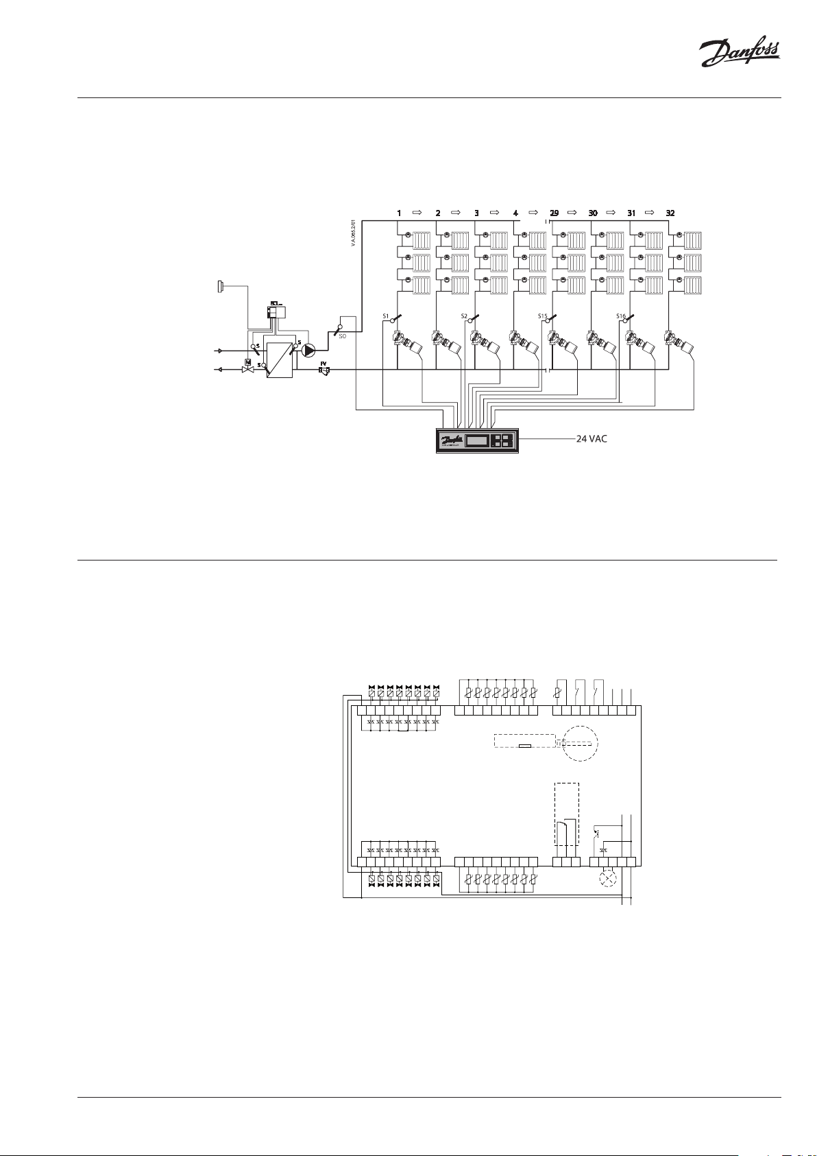
Fig. 4 CCR3 Controll er: scheme with 32 rise rs
Abb. 4 CCR3 Regler : Anlage mit 32 Strängen
4 pav. CCR3 reguliato rius: schema su 32 stovais
4. att. Reg ulators CCR3: shēma ar 32 stāv vadiem
Rys. 4 Sterow nik CCR3: schemat z 32 piona mi
Рис.4 Контролл ер CCR3: Схема с 32 стояками
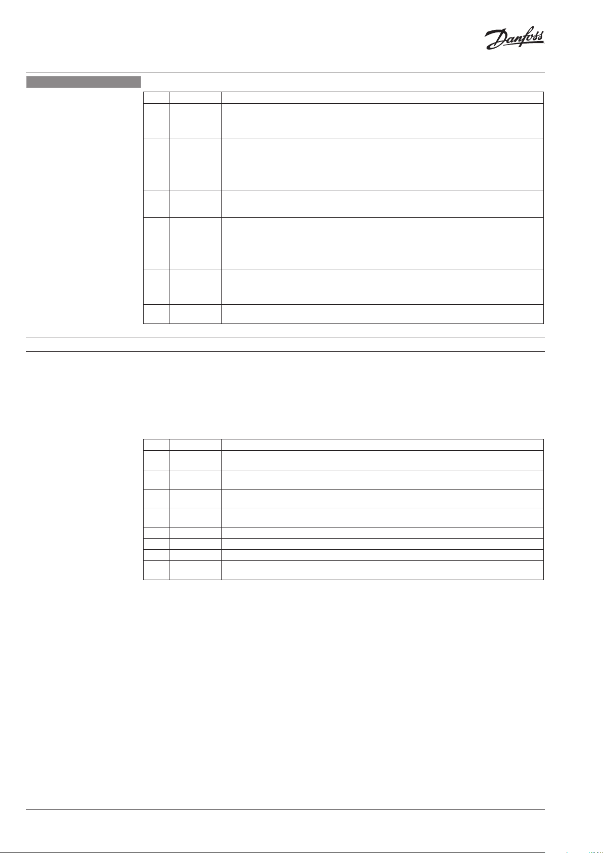
Fig. 5 Wiring
Abb. 5 Verdrahtun g
5 pav. Sujungim as
5. att. Vadojums
Rys. 5 Podł ączenia elek tryczne
Рис.5 Подключение силовых цепей
outlet: ac tuators 1-8
Triac output
Ausgang: Antriebe 1-8
Triac-Ausgang
Išėjimas: pavaros 1–8
TRIAC išė jimas
izeja: izpildmehānismi 1–8
TRIAC izvade
wylot: siłowniki 1–8
Wyjście triakowe
выход: прив оды 1-8
Триак-выход
C
V2 V3 V4 V5 V6 V7 V8
V1
CCR3
CONTROLLER
V13
V10 V9
C
outlet: ac tuators 9-16
Triac output
Ausgang: Antriebe 9-16
Triac-Ausgang
Išėjimas: pavaros 9-16
TRIAC išė jimas
izeja: izpildmehānismi 9-16
wylot: siłowniki 9–16
Wyjście triakowe
выход: прив оды 9-16
Триак-выход
V11 V12
TRIAC izvade
V15 V16
V14
temperature sensors
S1-S8
Temperaturfühler
S1-S8
Temperatūros jutikliai
S1–S8
temperatūras sensori
S1–S8
czujniki temperatury
S1–S8
температурные датчики
S1-S8
M S1 S2 S3 S4 S5 S6 S7 S8
M S9 S10 S11 S12 S13 S14 S15 S16
temperature sensors
temperature sensors
S9-S16
S9-S16
Temperaturfühler
Temperaturfühler
S9-S16
S9-S16
Temperatūros jutikliai
Temperatūros jutikliai
S9–S16
S9–S16
temperatūras sensori
temperatūras sensori
S9–S16
S9–S16
czujniki temperatury
czujniki temperatury
S9–S16
S9–S16
температурные датчики
температурные датчики
S9-S16
S9-S16
temp.
Free
sensor
contacts /
S0
temp.
fühler
S0
Temp.
jutiklis
S0
temp.
sensors
S0
czujnik
bezpotencjałowych/
temp.
S0
темп..
датчик
S0
M B1 M B2 M M A
S0 B
NO T1
C
NC
Input
Potentialfreie
Kontakte /
Eingabe
Nemokama
kontaktai/
įėjimas
Bezmaksas
kontakti /
Ievade
Styków
Wejście
Контакты
без /
Ввод
„ModBus“ „do BMS“
0V 0V 24V
T2
ModBus do BMS
ModBus do BMS
ModBus un BMS
ModBus do BMS
шина ModBus
выполнить BMS
ALARM
Supplay
voltage 24
Netzspannung
24 VAC
Maitinimo
įtampa 24 V
kintamoji srovė
Padeves
spriegums 24 V
maiņstrāva
Napięcie
zasilające
24 V AC
Напряжение
питания 24 В
пер. тока
RS 485
Fbus
RS 485
Fbus
RS 485
„Fbus“
RS 485
FBus
RS 485
FBus
RS 485
FBus
VAC
VI.D3.A3.02
© Danfoss |2016.08 | 3

CCR3 Controller
ENGLISH
1. Product description
2. Application
The CCR3 Controller is a controller used to control
return temperature in one pipe heating systems
with functions such as temperature registration
and monitoring riser temperature. The controller
is connected to thermo actuators type TWA-Z (NO)
and remote temperature sensors PT1000, type
ESMC installed on each riser.
CCR 3 controller is part of AB-QTE solution for
one-pipe heating systems. It converts one-pipe
heating system (usually constant flow system)
into efficient variable flow system. This innovative
solution dynamically controls the flow in the
riser according to the load in risers by return
temperature control. There are few basic rules to
be followed, even more valid in case of renovation:
• Set AB-QM according to the required heat load
of the riser/loop.
• Ensure correct radiator a bypass flow setting
(typically around 25-35 %). If the resistance of
the radiator is much too high compared to the
bypass this may result in underflow through
radiator if the flow in riser/loop is reduced.
3. Technical data: CCR3 Controller
Temperature sensor (S0, S1-S16)
Temperature range (registration) –20 °C … +120 °C
Measuring accuracy +/- 0,5 K
Inputs: B1 and B2 Free contact (5 V 1 mA)
Number of control valves (risers)
Output signal to actuators (Triac t ype) 24 VAC max. 1 A
Alarm signal output (Triac type) 24 VAC max. 1 A
Relay output 0-24 VAC/DC max. 1A
OC output ( Transistor type) 0-20 VDC NPN Open collec tor max. 200 mA
Type of memor y card (included) SD
Maximum memory card 2 GB (included)
Timer: Real time clock
Ambient temperature 0 … +50 °C ( for CCR3 only. The ambient temperature for actuators
Transport temperature –10 … +60 °C
IP rating IP 20
Power supply 24 VAC
Power consumption 6 VA
Weight 0,9 kg
Installation DIN rail 35 mm
• Optimise flow temperature that is driven by
substation control (too high flow temperature
can influence efficiency of first radiators in the
riser/loop and result in oscillation of flow).
• Optimise return temperature that is driven by
CCR 3 (too high return temperature can result in
lower energy efficiency).
• Install temperature sensor in front of AB-QM
as close to last radiator in the riser/loop as
possible.
Following above rules will ensure optimal control
performance of CCR3 as well as energy efficiency
and reliability of heating systems. For further
application insights please contact Danfoss
representative.
Pt1000, S0
16 basic, additional 16 with parallel connection ( 32 all together ,
one temperature sensor is used as common for two risers )
Built-in bat tery
– type ESMC/ESM11, S1-S16 – type ESMC
– powered for 10 years
TWA-Z (NO) should not be above 30 °C)
4 | © Danfoss | 2016.08
VI.D3.A3.02

CCR3 Controller
ENGLISH
LANGUAGE
4. Installation
For easy access the CCR3 Controller is installed in the
technical box on DIN rail 35 mm. Box with DIN rail
should be mounted in the wall (sub-station or
boiler
DIN rail
to install
same box as CCR3 (not supplied).
5. Switching the control on
Before switching the controller on for the first
time, disconnect all cables and connect a 24 VAC
source to the disconnected power plug. Use a
voltmeter to measure the voltage on the power
cable plug before it is connected to the controller.
If the voltage is correct:
1. Read the instructions before you operate the
2. Disconnect all cables
3. Connect the power to the transformer (not
4. Turn the power to the transformer on
5. Verified currency – 24 V
6. Connect the cable from the transformer to the
6. Control start menu
room) as close as possible to the heat source.
and box are not included. It is recommended
the standard 24 VAC transformer in the
controller
connected to CCR3 ”one”)
CCR3 Controller input
The transformer power depends on numbers of
actuators (number of risers in heating installation).
For standard application (16 actuators-16 risers)
30 W transformer is recommended, (for 32
actuators-32 risers) 60 W recommended.
Do not install (and remove) SD card when the CCR3
is connected to the current. It must be turned off (risk
of losing data).
The controller should display its name and the
software version – CONTROLLER START MENU –
display according to point 5.
Before any plugs are connected to the controllers,
input and output connectors:
1. Set all parameters on the controller
2.
Make sure that there is no external voltage on the
temperature sensor plugs
3. Make sure that the voltage on the relay contacts
is not too high (max. 24 VAC)
Start process
After switching the controller detected SD card on
and verified card memory.
If the card is placed correctly, the controller will verify
the present files:
• access
• one set
• all set
If the above-mentioned file is detected, the
controller
will ask whether it should be used or
aborted.
If no files (new card, used for the first time) there will
be no request.
The next controller will automatically generate a folder
with files:
• folder ACCESS:
allow change of access code to menu (details
on request or www.danfoss.com side)
•
folder DATA: file with record date folder SETTINGS
No. LCD Dis play FUNCTION DESCRIPTION
1 Danfoss
OPCCR -3.20
2 SD Free
.....
3 SD Free
199 6 MB
4 NO
SD CARD!
5 072254
123 456
Welcome Menu
Abbreviation: the type of the CCR3 Controller
Diagnosis: available SD card memory
Available memory In MB
e.g.: 2 GB
No SD card in CCR3
Only when no card in CCR3
Series number of CCR3 and number of software.
Code used for services.
with files
-
all set: file with settings. Each time the of control is
switched on, setting parameters are archived.
function provides verification history of all settings
- arch.set: file with archive of all settings.
Switching the controller on for the 2nd time with the
above-mentioned record file the request procedure
for setting change or abortion will start.
Display information during the start process
After switching the CCR3 Controller on, the LCD
display automatically presents the start menu.
The table below shows the various information
and change possibilities during the operation of
CCR3 Controller.
This
VI.D3.A3.02
© Danfoss | 2016.08 | 5

CCR3 Controller
ENGLISH
7. Control reading menu
When the setup is complete, the reading display
will be shown on the screen.
Pressing the “+” key turns the subsequent reading
display on. The “-” key turns the previous reading
display on.
No. LCD Dis play FUNCTION DESCRIPTION
6 Sensor0
…………
7 Valv e1
…….
8 SetT R1
…….
9 Time
………
10 Archiver
AC xx
11 DayToE nd
……..
12 Alert T2
…….
8. Menu Access Code - access to settings
Pressing an arrow “▲” result in exit from the reading
displays and enter to the ACCESS CODE menu,
described in chapter 8.
When exit from the menu the first reading display
is shown. A list of readings and possible displayed
options are shown in the table below.
Current return temperature measure by sensors.
Information: S0 – supply temperature, S1-S16 – return temperature measure in risers.
When info display Sensor .... Open ( no sensor ), when : Sensor ..... Closed ( short cut ).
Status of control valves, display from V1-V16
Information:
0 % ON no control signal for ac tuators (valve fully open when NO is used) or 100 % OFF (valves is closed).
During the controlling intermediate status is displayed: e.g. 17 %
Information about setting return temperature correspondent to current flow temperature, in C degree.
Display for R1-R16, e.g.: 45,0 °C
Current date and time
e.g .: 10- 04-27
17:45:10
Information about number of data storage in SD card(files)
e.g.: 38 storage file, InProces
xx = number of stored files; 1 file stored per day
Information how many days data can be stored on existing SD card.
Please note that this is information valid for current archiving interval.
e.g.: 884
Alarm output active or not . Function used for sensor and actuators circuit detection
(for example shortcut detection)
No Active or Active
To set the parameters, press the up arrow key “▲”
from R
eading Menu
and enter the access code (three
digits) to enter the required settings group.
The “+/-“ keys change the digit values in the code,
the arrow keys “▲/▼”navigate the cursor through
the code digits.
No LCD Display FUNCTION DESCRIPTION
13 AcceCode
***
Access codes to the controller’s setting menus. Available menus:
– Install Menu (code: 427). Advanced settings
– Real Time menu (code 576).Real time clock and date setting
- Control Menu (code 437): exp ert settings for PID control
Quadruple pressing up arrow key “▲” without ente ring any code will give access to “SD Card Exchange”.
–
SD card can be safely pulled out from CCR3 (process of date
recording is interrupted).
The access codes are standard for the individual
menus.
It is possible to change the access codes by
entering new codes through the SD memory
card and restarting the controller. Detailed
instructions are available on request.
The controller’s settings can be entered using the
keypad or globally through the SD memory card
(controller restart required). Details are available
on request.
To enter the required setting group press arrow key
“▲” after last code digit. If the code is not correct,
the display shows:
SD Card Exchange – this means that the SD card can
safely be pulled out from CCR3 "One pipe controller"
(process of date recording is interrupted). The settings
menu is closed automatically after four minutes of
inactivity and the display returns to
Reading Menu.
The manufacturer reserves the right to change the
controller’s settings and readings in production to
improve handling and functionality. An up-to-date
list of settings for the given software version is
available on Danfoss’ web site. New settings can
automatically upgrade CCR3 Controller through
the SD memory card (controller restart required).
6 | © Danfoss | 2016.08
VI.D3.A3.02

CCR3 Controller
ENGLISH
9. INSTALL MENU SETTINGS (Code: 427)
From ACCESS CODE menu enter code: 427
(procedure in chapter 7). The Install Menu is displayed
in details in the table below. The arrow keys “▲/▼”
move the menu windows, the “+/ - “keys change the
To exit the setting menu, press the up arrow key “▲”
after changing the last setting. The setting menu is
closed automatically after 4 minutes of inactivity.
values in the window selected by the arrows.
No LCD Display FUNCTION DESCRIPTION
14 INSTALL
Menu
15 TRet (35)
.....
16 TRe t (40)
.....
17 TRet (45)
.....
18 TRet (50)
.....
19 TR et (55)
.....
20 TRet (63)
.....
21 TRet (70)
.....
22 TRet (80)
.....
23 TRet (90)
.....
24 Shift1
..0 °C..
25 RiserNr 16Number of risers used in the system: settings from: 1-16
26 V Type
…….
27 VCharact
…….
28 Cor Cal
S0 ….
…. °C
29 Rel.Test
……….
Information about menu: Install
Recommended for service.
Required return temperature for measure supply temperature: 35 °C
Factory setting: 30 °C
Required return temperature for measure supply temperature: 40 °C
Factory setting: 34 °C
Required return temperature for measure supply temperature: 45 °C
Factory setting: 38 °C
Required return temperature for measure supply temperature: 50 °C
Factory setting: 40 °C
Required return temperature for measure supply temperature: 55 °C
Factory setting: 42 °C
Required return temperature for measure supply temperature: 63 °C
Factory setting: 45 °C
Required return temperature for measure supply temperature: 70 °C
Factory setting: 48 °C
Required return temperature for measure supply temperature: 80 °C
Factory setting: 54 °C
Required return temperature for measure supply temperature: 90 °C
Factory setting: 58 °C
Shift return temperature valid for all setting points. It can be adjusted up and down. The lowest shift setting
is to 10 degrees (anti frost setting value).
Each riser can be adjusted individually, riser by riser (from 1 to 16)
Factory setting: 0 ºC; in range of ±10 °C
If more than 16 risers: choose 16 and connect selected risers parallel using one ac tuator’s output for t wo risers
(for two actuators) (max additional 16 risers)
Factory setting: 16
Type of control valves: normal open or normal closed
Option to choose: NO or NC
Factor y setting: NO
Type of valves characteristic
Option to choose: Linear or Hyperbolic
Factory setting: Linear (setting for 24 VAC actuator)
Sensor calibration: S0-S16 in range: ±9,9 °C
Do not make calibration when sensor cables are shorter then:
- for cable 0,75 mm
- for cable 1,00 mm
Correction factor
total length
(two - core cable)
in meter 0,5 0,75 1,00 1,5
10 - 0,2 - 0,1 - 0,1 - 0,1
15 - 0,5 - 0,3 - 0,2 - 0 ,1
20 - 0,4 - 0,3 - 0,2 - 0,1
25 - 0,5 - 0,3 - 0,3 - 0,1
30 - 0,6 - 0,4 - 0,3 - 0,2
35 - 0,7 - 0,5 - 0,4 - 0,2
40 - 0,8 - 0,5 - 0,4 - 0,2
45 - 0,9 - 0,6 - 0,5 - 0,2
50 - 1, 0 - 0,7 - 0,5 - 0,3
75 - 1,5 - 1,0 - 0,8 - 0,4
100 - 2,0 - 1,4 - 1, 0 - 0,5
125 - 2,5 - 1,7 - 1, 3 - 0,6
150 - 3,0 - 2,0 - 1, 5 - 0,8
Factory setting: 0 °C
Relay test (Triac output)
AUTO – normal working operation
V1-V16 – forced signal for valves output V1-V16
Rel C-NO - not used
T1 Out – not used
T2 Out – forced signal (24 VAC) for alarm T2.
Factory setting: Auto
2
– 10 meters,
2
– 15 meters.
cable cross section
2
(mm
)
VI.D3.A3.02
© Danfoss | 2016.08 | 7
CCR3 Controller
ENGLISH
No LCD Display FUNCTION DESCRIPTION
30 AlertRel
... …
31 Archiver
...
32 ArchFreq
...
33 DateForm Form of date display:
34 Reset
…….
35 Ecs?
+ YES
10. REAL TIME CLOCK SETTINGS (code 576)
Alarm output (Triac)
StillOn – continuos alarm signal: T2 – 24 VAC
Pulse – pulse alarm signal 24 VAC every second
Factory setting: Pulse
Information about data archiving:
Never – the feature is switched off,
1 File – data is stored in one file on the SD card,
2 Files – data is stored alternatively in two files to improve write reliability. This function decreases term of
date storage (twice).
Factory setting: 1 File
Data archiving interval. The time can be set to any value between 10 seconds and 4 hours. The data from
each day saved in different files (with data name).
Factory setting: 1 min
YY-MM- DD – year, month, day
YY-DD-MM – year, day, month
DD-MM-YY – day, month, year
MM-DD - YY – month, day, year
Factory setting: YY-MM-DD
Reset to factory settings
Yes - return to factory settings
No – keep adjust settings
Note: To complete reset proced ure turn CCR3 off and back on.
Exit win dows from Install Men u. Enter “+” to closed set ting or basic menu will close automatically af ter 4 minutes
From ACCESS CODE menu enter code: 576
(procedure in chapter 7). The Real Time menu is
displayed as detailed in the table below.
The arrow keys “▲/▼”move the menu windows,
the “+/-“keys change the values in the window
selected by the arrows.
No LCD Display IN STALL MENU - FUNCTION DESCRI PTION
36 Real Time
Menu
37 RealTime
12:00:00
38 RealTime
12:00:00
39 RealTime
12:00:00
40 Year Sets the year for the current date
41 Month Sets the month for the current date
42 Day Sets the da y for the current date
43 Ecs?
+ YES
Information about menu: real Time
Sets the real time clock “hour”
Sets the real time clock “minute”
Sets the real time clock “second”
Exit win dows from Install Men u. Enter “+” to closed set ting or basic menu will close automatically af ter 4 minutes
To exit the setting menu, press the up arrow key after
changing the last setting. The setting menu is closed
automatically after 4 minutes of inactivity.
8 | © Danfoss | 2016.08
VI.D3.A3.02

CCR3 Controller
ENGLISH
11. CONTROL MENU (code 437)
From ACCESS CODE menu enter code: 437
(procedure in chapter 7). The Control menu is
displayed as detailed in the table below. The arrow
keys “▲/▼”move the menu windows, the “+/-“keys
change the values in the window selected by
the arrows. To exit the setting menu, press the
up arrow key after changing the last setting.
The setting menu is closed automatically after 4
minutes of inactivity.
No LCD Display FUNCTION DESCRIPTION
44 Prop. Fac ……Control gain of control signal (depend on actuators typ e). The higher gain control the bigger valves reac tion
45 Int.Time
46 Diff.Ti me
47 PWM Per
48 PWM Min
49 PWM Max
50 BMSAdres
51 BMS TYPE
52 Ecs?
…….
…….
…….
…….
…….
…..
…….
+ YES
(no stable regulation). The lower gain control weak reaction for temperature change (stable regulation).
Factory setting: 50 (for dedicated T WA-Z (NO) actuators); setting range 1-100
Integration time of the control signal (depend of actuators type). The shorter time, quicker temperature
changes (no stable regulation). The longer time slower reaction for temperature change (stable regulation).
Factory setting: 6 sec (for dedicated TWA-Z (NO) actuators); set ting range 1-100
Differential time of control signal. The longer the value, faster control in reaction to the control value
change - approaching to the set value but not reaching it yet. Too high value resu lts in unstable control.
Factory setting: 15
Time period of pulse width madulation (PWM}.
Factory setting: 10s
At »close« signal to actuator, PWM describes minimum % of open period to the actuator. Lower the
value, longer the reac tion time of the actuator. Too high value can result in not closed valve.
Factory setting: 10 %
At »open« signal to actuator, PWM describes maximum % of open period to the actuator. Higher the
value, longer the reac tion time of the actuator. Too low value can resu lt in not opened valve.
Factory setting: 90 %
CCR3 address in BMS system
Factory setting: 1
Type of date transmission:
ModBus 96 (9.600)
Mod Bus 19 (19.000)
ModBus 38 (38.400)
FBus
Factory setting: Mod Bus 96
Exit win dows from Install Men u. Enter “+” to closed set ting or basic menu will close automatically af ter 4 minutes
12. USING THE DATA STORAGE CARD
The SD card may never be installed or removed from
the CCR3 Controller when data is being written to it,
this may lead to:
– data loss
– SD card damage
– CCR3 Controller damage.
INSTALLING THE SD CARD
Disconnect the controller from the power supply for
at least five seconds before inserting the SD card.
The SD card may only be installed after this pause.
REMOVING THE SD CARD
From ACCESS CODE menu quadruple press up arrow
key “▲” without entering any code it will give access
to “SD Card Exchange”. SD card can be pulled out
safely from CCR3 Controller (process of date recording
is interrupted).
Power failures occur as data written to the SD card may
also corrupt the archive or even damage files stored
on the card. To reduce this risk, it is recommended
to use a buffered power supply for a CCR3 Controller
used with the data archiving function and to set the
“Archive” setting to “2 Files.” The archive files will be
doubled, but the storage space will drop by half.
VI.D3.A3.02
© Danfoss | 2016.08 | 9

CCR3 Controller
Danf
already on order pro
All trademarks in this material are property of the respec
ENGLISH
13. CCR3 ModBus PROTOCOL
Data type: Coil [bool] Coil No. Description
MB_CoilOut [2 … 9] - open valves (0 … 7)
MB_CoilOut [10 … 17] - risers with open valves (riser: 8 … 15)
Data type: Register
[integer]
Baud rate:
Register No. Description
MB_RegisterOut [0 … 8] - temperature sensors S0 … S8 (8000 <=> 80 °C)
MB_RegisterOut [9 … 16] - temperature sensors S9 … S16 (8000 <=> 80 °C)
MB_RegisterOut [17 … 24] - temperature setting for risers 1 … 8
MB_RegisterOut [25 … 32] - temperature setting for risers 9 … 16
MB_RegisterOut [36+0 … 7] - control signal (opening) in % for valve in risers: 1 … 8
MB_RegisterOut [44+0 … 7] - control signal (opening) % for valve in riser: 9 … 16
data bits stop bits parity
9.600 8+1 N
19.200 8+1 N
38.400 8+1 N
oss can accept no responsibility for possible errors in catalogues, brochures and other printed material. Danfoss reserves the right to alter its products without notice. This also applies to products
vided that such alterations can be made without subsequential changes being necessary eady agreed.
10 | © Danfoss | DHS-SRMT/SI | 2016.08
tive companies. Danfoss and the Danfoss logotype are trademarks of Danfoss A/S. All rights reserved.
73693840/VI.D3.A3.02
 Loading...