

Page 1
Operating Guide
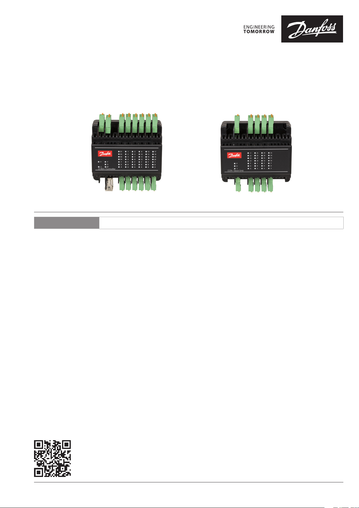
CCR2+ Controller
Master Controller Slave Unit
ENGLISH
CCR2+ Disinfection Process Control & Temperature Registration www.danfoss.com
© Danfoss | 2022.01
AQ282339078428en-010203 | 1
Page 2
CCR2+ Controller
1219 20 21 ... 35 36
6
A
1278910 19 20
A
TVM
12789 19 20
TVM
TVM
TVM
TVM
TVM
TVM
TVM
...
LBus
24VDC
RS485
A1-4
C
V1-4
C
C
V5-8CV9-12
C
V13-16
C
V17-20
CCR2+ Controller
TCP/IP
RJ45
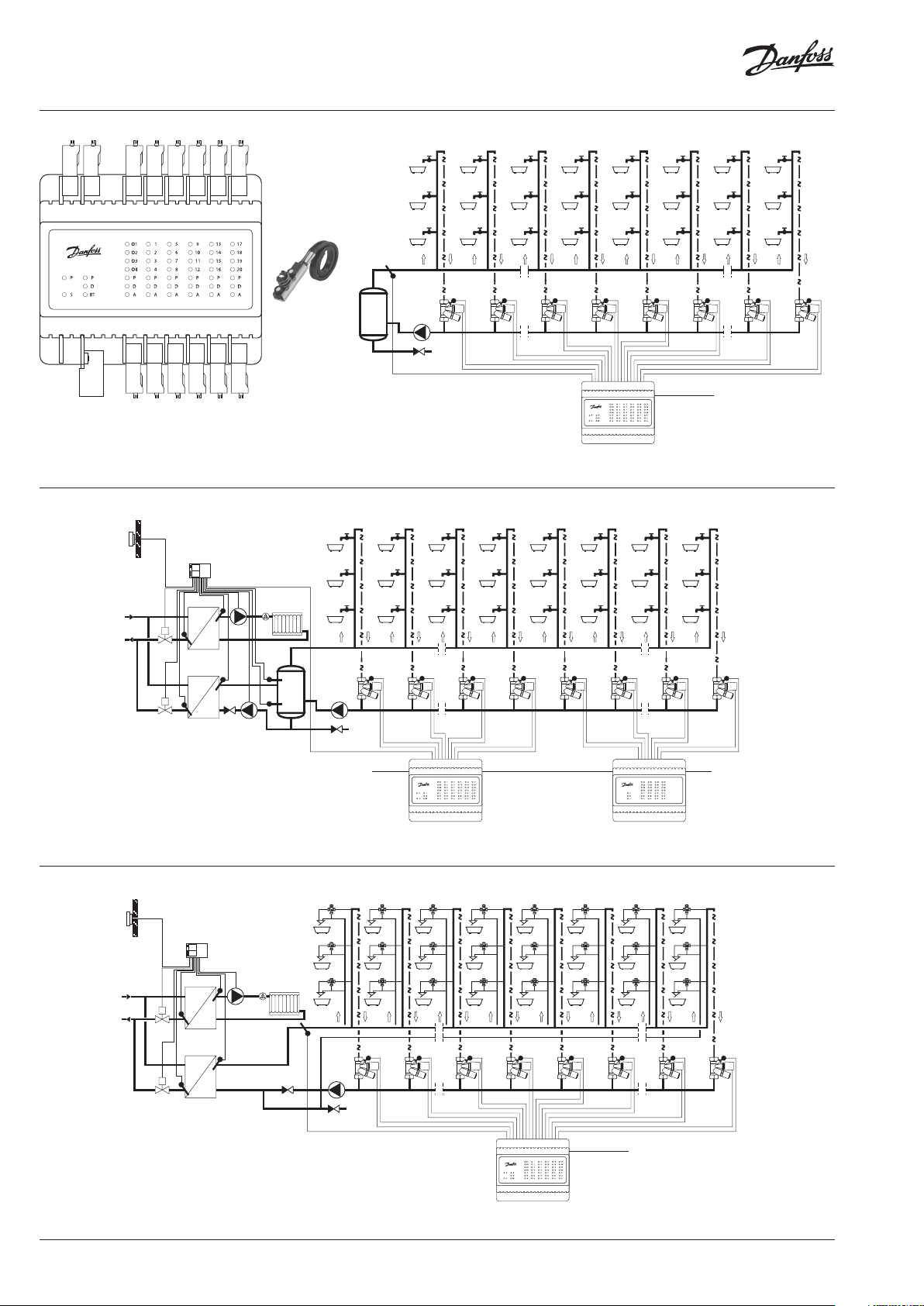
Fig. 1 CCR2+ & ESMC
S5-8 S9-12
B1-3 S0
S1-4
GGGGGG
S13-16
S17-20
ECL...
M
S
S
S
M
S
S0
S1
MTCV
S2 S7 S8 S9 S10 S19 S20
V1
TWA
V2
TWA
V7
TWA
V8
TWA
V9
TWA
V10
TWA
MTCV MTCV MTCV MTCV MTCV MTCV MTCV
V19
TWA
V20
TW
24 VDC
Fig. 2 Installa tion with CCR2+ Controller (up to 20 risers/lo ops)
S
S
S1 S2 S19 S20 S21 S... S35 S36
MTCV
V1
TWA
V2
TWA
V19
TWA
V20
TWA
V21
TWA
V...
TWA
V35
TWA
MTCV MTCV MTCV MTCV MTCV MTCV MTCV
V3
TW
Fig. 3a Install ation with CCR2+ Controller (Master) and CCR+ Slave Unit (more th at 20 risers)
543
HC
MIX
ECL...
S
M
TVM
543
HC
MIX
TVM
543
HC
MIX
S
S0
S
M
S
MTCV
543
HC
MIX
TVM
543
HC
MIX
TVM
543
HC
MIX
S1
S2 S7 S8 S9 S... S19 S20
V1
TWA
MTCV MTCV MTCV MTCV MTCV MTCV MTCV
Fig. 3b
24 VDC24 VDC
543
HC
MIX
TVM
543
HC
MIX
TVM
543
HC
MIX
V2
TWA
543
HC
MIX
TVM
543
HC
MIX
TVM
543
HC
MIX
V7
TWA
543
HC
MIX
TVM
543
HC
MIX
TVM
543
HC
MIX
V8
TWA
543
HC
MIX
TVM
543
HC
MIX
TVM
543
HC
MIX
543
HC
MIX
TVM
543
HC
MIX
TVM
543
HC
MIX
543
HC
MIX
TVM
543
HC
MIX
TVM
543
HC
MIX
V9
TWA
V...
TWA
V19
TWA
V20
TWA
24 VDC
2 | © Danfoss | 2022.01
AQ282339078428en-010203
Page 3
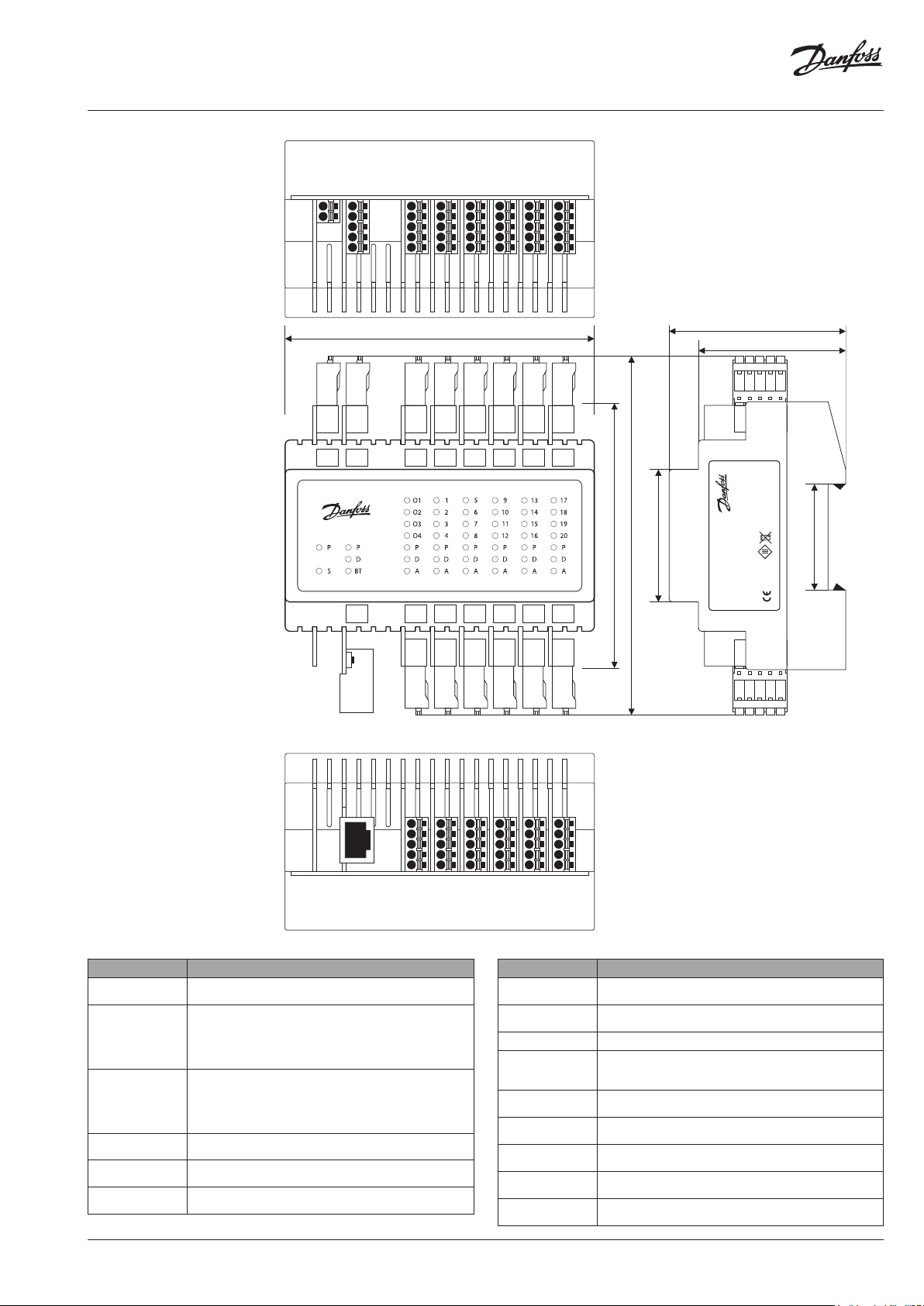
CCR2+ Controller
G
G
Lbus
24VDC
G
B
A
POWER
Master
LBus
0V
RS485
24VDC
CCR2+ Controller
TCP/IP
LAN
C
CCCCC
O4
V4
V8
V12
0
O3
V3
O2
O1
Module
V7
V2 V6 V10 V14 V18
V1
V5
Module 1
Module 2
V16
4
V11
V15
V9
V13
Module 3
Module
105 mm
C
O1-4
B1-B3 S0
G
V5-8CV9-12
V1- 4
S5-8 S9-12
S1-4
GGGGG
C
C
V13-16
S13-16
C
V20
5
V19
V17
Module
C
V17-20
S17-20
90 mm
122 mm
45 mm
Disinfection
60 mm
MADE IN POLAND
CCR2+
Process Controller
50 mm
20171213V2.40
003Z3851
Supply 24VDC
Danfoss A/S
6430 Nordborg, Denmark
36 mm
RoHS
Fig. 4a Wiring scheme - CCR+
Master Controller
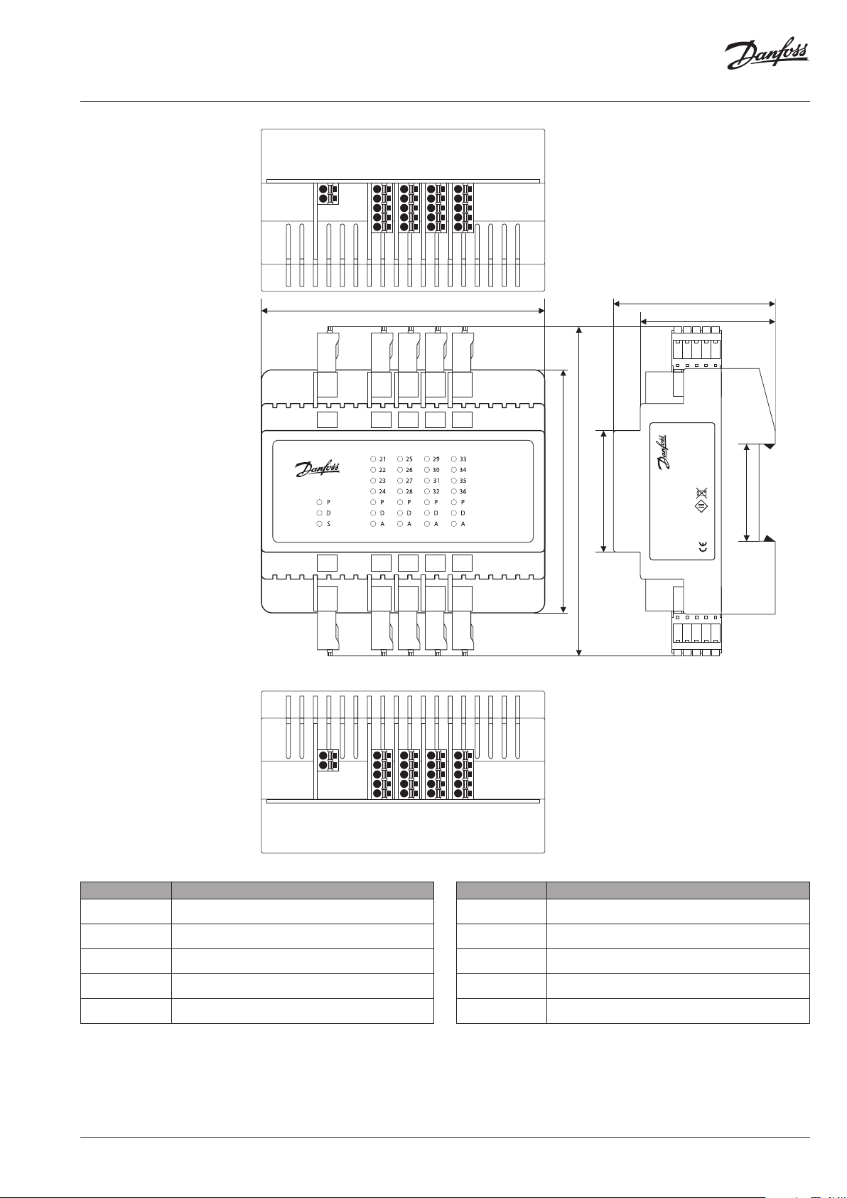
Connector/port Description
0V
24VDC
Lbus
RS485
C
O1,.. ,O4
C
V1-4
C
V5-8
C
V9 -12
0V – ground (-) power supply
24 V DC(+) power supply
G – ground Lbus port (for system expansion)
Lbus – Lbus port (for system expansion)
G – ground (Modbus RS 485)
B – port B (Modbus RS 485)
A - port A (Modbus RS 485)
C – common port dedicated to outputs O1-O4
O1 - output: Heat Force
O2 - output: Start next CCR/Slave Unit
O3 - output: Disinfection finished
O4 - output: Alarm
C – common port dedicated to actuators V1-4
V1..V4 – outputs to actuators
C – common por t dedicated to actuators V5-8
V5. .V8 – outputs to ac tuators
C – common port dedicated to actuators V9 -12
V9. .V12 – outputs to actuators
TCP/IP
RJ45
4
B1
TCP/IP
Master
POWER
RJ45
S2
B2
S3
B3
Module 1
Module 0
S4
S0
G
G
S10
S6
S11
S7
Module 2
Module
S12
S8
G
G
3
S9
S5
S1
S13
S14
S15
Module
S16
G
S17
S18
S19
Module 5
S20
G
Connector/port Description
C
V13 -16
C
V17-2 0
C – common port dedicated to actuators V13-16
V13..V16 – outputs to actuators
C – common port dedicated to actuators V17-20
V17.. V2 0 – outputs to ac tuators
TC P/ IP, L AN TCP/ IP port or IP Modbus port
B1-3, S0
G
S1-4
G
S5-8
G
S9 -12
G
S13 -16
G
S17-2 0
G
B1,B2, B3 defined inputs
S0 – temp. sensor
G – common ground dedicated to inputs/sensor
S1.. S4 – inputs from sensors
G – common ground dedicated to sensor S1-4
S5..S8 – inputs from sensors
G – common ground dedicated to sensors S5-8
S9. .S12 – inputs from sensors
G – common ground dedicated to sensors S9-12
S13.. S16 – inputs from sensors
G – common ground dedicated to sensors S13-16
S17. .S 20 – inputs from sensors
G – common ground dedicated to sensors S17-20
AQ282339078428en-010203
© Danfoss | 2022.01 | 3
Page 4
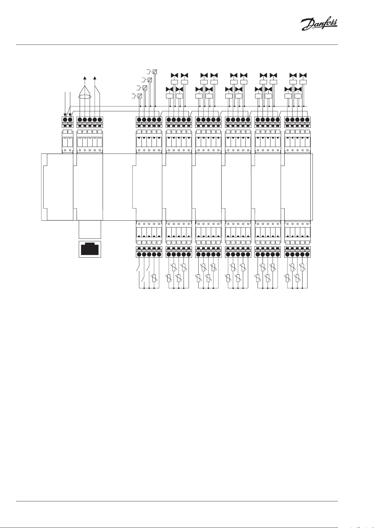
CCR2+ Controller
Actuators of risers’ valves V1...V20
B3 - ext. alarm
PT1000
Power
Supply
Board
POWER
SUPPLY
0VDC
24VDC
BMS
B
A
G
Master
Controller
Board
TCP/IP - LAN
CCR
Lbus
SLAVE
G
Alarm
Disinfection finished
Start next CCR
Heat force
24VDC
0V
Empty
Socket
Place
KO4
KO3
KO2
KO1
O1
O2
O4
O3
Module 0
Input / Output
Board
B1
B2
B3
S0
V2V3V4
V1
C
V1
Module 1
Input / Output
S1
G
V2
Board
S2
Open collector outputs connect to 0V
V8
V10
V12
V3
S3
V4
S4
C
G
V5V6V7
V6
V5
Module 2
Input / Output
Board
S5
S6
V7
S7
V8
S8
C
G
V9
V11
V9
V11
V10
Module 3
Input / Output
Board
S9
S10
S11
C
V12
S12
G
V14
V16
V13
V15
V14
V13
V16
V15
Module 4
Input / Output
Board
S13
S14
S15
S16
V18
V17
C
V17
Module 5
Input / Output
S17
G
V19
V18
Board
S18
V20
C
V20
V19
S20
S19
G
WEB SERVER
BMS TCP/IP
ETHERNET
INTERNET
B1 - start dis.
B2 - stop dis.
Fig. 4b Wiring scheme CCR2+ Master Controller
B1
B2
B3
S0
S0 - main
Risers’ temperature sensors S1...S20
sensor
Type of sensor - PT1000
4 | © Danfoss | 2022.01
AQ282339078428en-010203
Page 5
CCR2+ Controller
24VDC
Power
24VDC
CCR+ Slave
LBus
G
OV
G
C
V24
6
V23
V22
V21
Module
105 mm
C
V21-24
S21-24
G
C
V28
7
V27
V26
V25
Module
C
V25-28
S25-28
G
CC
V32
V36
V31
V35
V30 V34
V29
V33
Module 8
Module 9
C
C
V33-36
V29-32
S33-36
S29-32
G
G
90 mm
122 mm
45 mm
CCR+ Slave Unit
60 mm
50 mm
MADE IN POLAND
CCR+ Slave Unit
20171212VS.12
003Z3852
Supply 24VDC
Danfoss A/S
6430 Nordborg, Denmark
36 mm
RoHS
Fig. 5 Wiring Scheme - CCR+
Slave Unit
Connector/port Description
0V
24VDC
C
V21-24
C
V24 -28
C
V29-32
C
V30-36
0V – ground (-) power supply
24 VDC power supply
C – common port dedicated to actuators
V21..V 24 – outputs to ac tuators
C – common port dedicated to actuators
V24..V28 – outputs to actuators
C – common port dedicated to actuators
V29..V32 – outputs to actuators
C – common port dedicated to actuators
V33..V36 – outputs to actuators
AQ282339078428en-010203
Slave
G
Lbus
1
S29
S30
S31
Module
S32
2
S33
S34
S35
Module
S36
G
0
S25
S21
S26
S22
S27
S23
Module 0
Module
S28
S24
G
GG
Connector/port Description
Lbus
S21-24
G
S25 -28
G
S29-32
G
S33-36
G
G – ground Lbus port (for system expansion)
Lbus – Lbus port (for system expansion)
S21.. S24 – inputs from sensors
G – common ground dedicated to sensors
S25..S28 – inputs from sensors
G – common ground dedicated to sensors
S29.. S32 – inputs from sensors
G – common ground dedicated to sensors
S33..S36 – inputs from sensors
G – common ground dedicated to sensors
© Danfoss | 2022.01 | 5
Page 6

CCR2+ Controller
Heat forc
Start next CCR
Disinfection finished
Alarm- dis. faile
Connection of two CCR2+
with one S0 sensor in sequence mode
20180904
Connection of two CCR2+
with individual S0 sensor in sequence mode
Heat forc
Start next CCR
Disinfection finished
Alarm- dis. faile
20180904
Fig. 6 Connec tion of two CCR2+ with
one S0 sensor in sequence mode
24VDC
0V
d
KO2
KO1
e
O1
B1
B1
B2
B1 - start dis.
B2 - stop dis.
B3 - ext. alarm
C
C
C
G
C
G
C
G
C
G
V34
V33
V35
Module 4
Input / Output
Board
S33
S35
S34
V9
V11
V10
Module 3
Input / Output
Board
S9
S11
S10
V34
V33
V35
Module 4
Input / Output
Board
S33
S35
S34
V9
V11
V10
Module 3
Input / Output
Board
S9
S11
S10
V36
S36
V12
S12
V36
S36
V12
S12
C
G
C
Input / Output
G
C
G
C
Input / Output
G
V13
Module 4
S13
V13
Module 4
S13
V14
Board
S14
V14
Board
S14
C
C
V20
V16
V17
V19
V18
V15
Module 5
Input / Output
Board
S15
S16
S17
S19
S20
S18
G
G
C
C
V20
V16
V17
V19
V18
V15
Module 5
Input / Output
Board
S15
S16
S17
S19
S20
S18
G
G
V21
V22
V24
V23
V26
0VDC
Slave
24VDC
Board
B
A
Master 1
Controller
Board
Slave
Board
B
A
Master 1
Controller
Board
Empty
Socket
Place
G
Lbus
G
G
Lbus
Empty
Socket
Place
0VDC
24VDC
Empty
Socket
Place
G
Lbus
G
G
Lbus
Empty
Socket
Place
Power
Supply
Board
Power
Supply
Board
24VDC
24VDC
Controller
and Power
0VDC
TCP/IP - LAN
Controller
and Power
0VDC
TCP/IP - LAN
Supply
Supply
SECOND
SLAVE
UNIT
SECOND
MASTER
UNIT
KO4
KO3
MAIN
SLAVE
UNIT
C
O2
O4
O3
S0
G
B2
B3
B3
S0
S0 - main
sensor
PT1000
FORCE
HEATING
SOURCE
MAIN
MASTER
UNIT
KO1
Module 1
Input / Output
Board
S21
S23
S22
O1
O2
O3
Module 0
Input / Output
Board
B1
B2
B3
V21
V22
V23
Module 1
Input / Output
Board
S21
S23
S22
O1
O2
O3
Module 0
Input / Output
Board
B1
B2
B3
S24
O4
S0
V24
S24
O4
S0
Input / Output
G
C
Input / Output
G
C
Input / Output
G
C
Input / Output
G
V25
Module 2
Board
S25
V1
Module 1
Board
S1
V25
Module 2
Board
S25
V1
Module 1
Board
S1
S26
V2
S2
V26
S26
V2
S2
V31
V28
S28
V4
S4
V28
S28
V4
S4
Input / Output
G
C
Input / Output
G
C
Input / Output
G
C
Input / Output
G
V29
Module 3
Board
S29
V5
Module 2
Board
S5
V29
Module 3
Board
S29
V5
Module 2
Board
S5
V32
V30
S31
S32
S30
V7
V6
V8
S7
S8
S6
V31
V32
V30
S31
S32
S30
V7
V6
V8
S7
S8
S6
V27
S27
V3
S3
V27
S27
V3
S3
TEMP S.0
Fig. 7 Connec tion of two CCR2+ with
individua l S0 sensor in sequence mode
SECOND
KO4
d
KO3
KO2
KO1
e
24VDC
0V
C
O1
O2
O4
O3
S0
G
B1
B2
B3
B1
B2
B3
S0
S0 - main
sensor
PT1000
B1 - start dis.
B2 - stop dis.
B3 - ext. alarm
SLAVE
UNIT
SECOND
MASTER
UNIT
MAIN
SLAVE
UNIT
FORCE
HEATING
SOURCE
MAIN
MASTER
UNIT
C
C
C
G
C
G
V34
V33
V35
Module 4
Input / Output
Board
S33
S35
S34
V9
V11
V10
Module 3
Input / Output
Board
S9
S11
S10
V36
S36
V12
S12
C
G
C
Input / Output
G
V13
Module 4
S13
V14
Board
S14
C
C
V20
V16
V17
V19
V18
V15
Module 5
Input / Output
Board
S15
S16
S17
S19
S20
S18
G
G
Power
Supply
Board
24VDC
Controller
and Power
0VDC
TCP/IP - LAN
Slave
Supply
Board
B
A
Master 1
Controller
Board
V21
V22
V24
V23
V26
0VDC
24VDC
Empty
Socket
Place
G
Lbus
G
G
Lbus
Empty
Socket
Place
Module 1
Input / Output
Board
S21
S23
S22
O1
O2
O3
Module 0
Input / Output
Board
B1
B2
B3
S24
O4
S0
Input / Output
G
C
Input / Output
G
V25
Module 2
Board
S25
V1
Module 1
Board
S1
S26
V2
S2
V31
V28
S28
V4
S4
Input / Output
G
C
Input / Output
G
V29
Module 3
Board
S29
V5
Module 2
Board
S5
V32
V30
S31
S32
S30
V7
V6
V8
S7
S8
S6
V27
S27
V3
S3
TEMP S.0
C
C
C
G
C
G
V34
V33
V35
Module 4
Input / Output
Board
S33
S35
S34
V9
V11
V10
Module 3
Input / Output
Board
S9
S11
S10
V36
S36
V12
S12
C
G
C
Input / Output
G
V13
Module 4
S13
V14
Board
S14
C
C
V20
V16
V17
V19
V18
V15
Module 5
Input / Output
Board
S15
S16
S17
S19
S20
S18
G
G
V21
V22
V24
V23
V26
0VDC
Slave
24VDC
Board
B
A
Master 1
Controller
Board
Empty
Socket
Place
G
Lbus
G
G
Lbus
Empty
Socket
Place
Controller
and Power
Supply
KO1
0VDC
24VDC
Power
Supply
Board
TCP/IP - LAN
Module 1
Input / Output
Board
S21
S23
S22
O1
O2
O3
Module 0
Input / Output
Board
B1
B2
B3
S24
O4
S0
Input / Output
G
C
Input / Output
G
V25
Module 2
Board
S25
V1
Module 1
Board
S1
S26
V2
S2
V31
V28
S28
V4
S4
Input / Output
G
C
Input / Output
G
V29
Module 3
Board
S29
V5
Module 2
Board
S5
V32
V30
S31
S32
S30
V7
V6
V8
S7
S8
S6
V27
S27
V3
S3
TEMP S.0
6 | © Danfoss | 2022.01
AQ282339078428en-010203
Page 7

CCR2+ Controller
Heat forc
Connection of two CCR2+
with one S0 sensor in sequence mode
20180904
Connection of two CCR2+
with individual S0 sensor in sequence mode
Heat forc
Start next CCR
Disinfection finished
Alarm- dis. faile
20180904
Fig. 8 Connec tion of two CCR2+ with
individual S0 sensor in parallel mode
Alarm- dis. failed
Disinfection finished
Start next CCR
e
24VDC
0V
KO4
KO3
KO2
KO1
O1
O2
O4
O3
S0
B1
B2
B3
B1
B2
B3
S0
B1 - start dis.
B2 - stop dis.
B3 - ext. alarm
C
G
S0 - main
sensor
PT1000
SECOND
SLAVE
UNIT
SECOND
MASTER
UNIT
MAIN
SLAVE
UNIT
FORCE
HEATING
SOURCE
MAIN
MASTER
UNIT
C
C
C
Input / Output
G
C
Input / Output
G
V33
Module 4
Board
S33
V9
Module 3
Board
S9
C
V34
V36
V35
S35
S36
S34
G
C
C
Input / Output
G
V17
Module 5
Board
S17
C
V20
V19
V18
S19
S20
S18
G
V11
V12
V14
V13
S12
G
V15
Module 4
Input / Output
Board
S13
S15
S14
V16
S16
V10
S11
S10
Power
Supply
Board
24VDC
Controller
and Power
0VDC
TCP/IP - LAN
Slave
Supply
Board
B
A
Master 1
Controller
Board
V21
V22
V24
V23
V26
0VDC
24VDC
Empty
Socket
Place
G
Lbus
G
G
Lbus
Empty
Socket
Place
Module 1
Input / Output
Board
S21
S23
S22
O1
O2
O3
Module 0
Input / Output
Board
B1
B2
B3
S24
G
C
O4
S0
G
V25
Module 2
Input / Output
Board
S25
S26
V1
V2
Module 1
Input / Output
Board
S1
S2
V31
V28
S28
V4
S4
Input / Output
G
C
Input / Output
G
V29
Module 3
Board
S29
V5
Module 2
Board
S5
V32
V30
S31
S32
S30
V7
V6
V8
S7
S8
S6
V27
S27
V3
S3
TEMP S.0
C
C
C
Input / Output
G
C
Input / Output
G
V33
Module 4
Board
S33
V9
Module 3
Board
S9
C
V34
V36
V35
S35
S36
S34
G
C
C
Input / Output
G
V17
Module 5
Board
S17
C
V20
V19
V18
S19
S20
S18
G
V11
V12
V14
V13
S12
G
V15
Module 4
Input / Output
Board
S13
S15
S14
V16
S16
V10
S11
S10
V21
V22
V24
V23
V26
0VDC
Slave
24VDC
Board
B
A
Master 1
Controller
Board
Empty
Socket
Place
G
Lbus
G
G
Lbus
Empty
Socket
Place
Controller
and Power
Supply
KO1
0VDC
24VDC
Power
Supply
Board
TCP/IP - LAN
Module 1
Input / Output
Board
S21
S23
S22
O1
O2
O3
Module 0
Input / Output
Board
B1
B2
B3
S24
G
C
O4
S0
G
V25
Module 2
Input / Output
Board
S25
S26
V1
V2
Module 1
Input / Output
Board
S1
S2
V31
V28
S28
V4
S4
Input / Output
G
C
Input / Output
G
V29
Module 3
Board
S29
V5
Module 2
Board
S5
V32
V30
S31
S32
S30
V7
V6
V8
S7
S8
S6
V27
S27
V3
S3
TEMP S.0
Fig. 9 Connection of two CCR2+ with one
S0 sensor in parallel mode
SECOND
KO4
d
KO3
KO2
KO1
e
24VDC
0V
C
O1
O2
O4
O3
S0
G
B1
B2
B3
B1
B2
B3
S0
S0 - main
sensor
PT1000
B1 - start dis.
B2 - stop dis.
B3 - ext. alarm
SLAVE
UNIT
SECOND
MASTER
UNIT
MAIN
SLAVE
UNIT
FORCE
HEATING
SOURCE
MAIN
MASTER
UNIT
C
C
C
Input / Output
G
C
Input / Output
G
C
Input / Output
G
C
Input / Output
G
V33
Module 4
Board
S33
V9
Module 3
Board
S9
V33
Module 4
Board
S33
V9
Module 3
Board
S9
C
V34
V36
V35
S35
S36
S34
G
C
C
Input / Output
G
C
Input / Output
G
V17
Module 5
Board
S17
V17
Module 5
Board
S17
C
V20
V19
V18
S19
S20
S18
G
C
V20
V19
V18
S19
S20
S18
G
V11
V12
V14
V13
S12
V36
S36
V12
S12
G
C
G
C
G
V15
Module 4
Input / Output
Board
S13
S15
S14
V14
V13
V15
Module 4
Input / Output
Board
S13
S15
S14
V16
S16
V16
S16
V10
S11
S10
V34
V35
S35
S34
V11
V10
S11
S10
V21
V22
V24
V23
V26
0VDC
Slave
24VDC
Supply
Board
B
A
Master 1
Controller
Board
Slave
Supply
Board
B
A
Master 1
Controller
Board
Empty
Socket
Place
G
Lbus
G
G
Lbus
Empty
Socket
Place
0VDC
24VDC
Empty
Socket
Place
G
Lbus
G
G
Lbus
Empty
Socket
Place
Controller
and Power
0VDC
24VDC
Power
Supply
Board
TCP/IP - LAN
Controller
and Power
KO1
0VDC
24VDC
Power
Supply
Board
TCP/IP - LAN
Module 1
Input / Output
Board
S21
S23
S22
O1
O2
O3
Module 0
Input / Output
Board
B1
B2
B3
V21
V22
V23
Module 1
Input / Output
Board
S21
S23
S22
O1
O2
O3
Module 0
Input / Output
Board
B1
B2
B3
S24
O4
S0
V24
S24
O4
S0
G
C
G
C
G
C
G
V25
Module 2
Input / Output
Board
S25
S26
V1
V2
Module 1
Input / Output
Board
S1
S2
V26
V25
Module 2
Input / Output
Board
S25
S26
V1
V2
Module 1
Input / Output
Board
S1
S2
V31
V28
S28
V4
S4
V28
S28
V4
S4
Input / Output
G
C
Input / Output
G
C
Input / Output
G
C
Input / Output
G
V29
Module 3
Board
S29
V5
Module 2
Board
S5
V29
Module 3
Board
S29
V5
Module 2
Board
S5
V32
V30
S31
S32
S30
V7
V6
V8
S7
S8
S6
V31
V32
V30
S31
S32
S30
V7
V6
V8
S7
S8
S6
V27
S27
V3
S3
V27
S27
V3
S3
TEMP S.0
AQ282339078428en-010203
© Danfoss | 2022.01 | 7
Page 8

CCR2+ Controller
Temperature sensor (S0, S1-S20 / S21-36)
Pt1000, S0- type ESMC / ESM11, S1 … S36 – type ESMB
Temperature range (registration)
–20 °C … +120 °C
- IP Modbus (L AN cable connection)
- default password: admin1234
1. Product description
2. Technical data
The CCR2+ is a control used for optimizing
the thermal disinfection process in hot water
systems with functions such as temperature
registration and monitoring circulation hot water
actuators type TWA-A and remote temperature
sensors PT1000, type ESMB, installed on each
thermostatic circulation valve, type MTCV
(Multifunctional Thermostatic Circulation Valve).
systems. The control is connected to thermo
Measuring accuracy ± 0,1 K
Inputs: B1, B2 and B3 Free contact (5 V 1 mA)
Number of control valves (risers) 20, additional 16 with system extension via CCR+ Slave Unit
Output signal to actuators 24 VDC max. 1 A
Alarm signal output 24 VDC max. 1 A
Relay output 0 … 24 DC max. 1 A
Type of memory Build-In
Capacity of memor y 8 GB
Timer: Real time clock Built-in bat tery - service life 10 years
- Wi-Fi (communication p ort only)
Communication interfaces
Default IP settings
- TPC/IP port (LAN cable connection)
- Modbus RS 485 RTU
- Default L AN IP address (static): 192.168.1.100
- Default WiFi access IP address (static): 192.168.1.10
- IP address mask: 255.255.255.0
- Gat eway addr ess: 192 .168.1.1
- DNS ad dress: 192.16 8.1.1
- CCR name: ccrplus
1)
To select proper p ower transformer
please follo w formula: 24 V 10VA
(controller) + 7 VA*/per each actuator
3. Installation
Ambient temperature 0 … 50 °C
Transport temperature –10 … +60 °C
IP rating IP 20,
Power supply 24 VDC
Power consumption (Master controller only)
Power consumption (Slave Unit only)
Weight 0.3 kg
Installation DIN rail 35 mm
1)
1)
10 VA
3 VA
For easy access, the CCR2+ controllers should
be installed in electrical enclosure on DIN rail 35
mm. Enclosure with DIN rail should be mounted
onto the wall (sub - station or boiler room) as
close as possible to the heat source. DIN rail and
enclosure are not included.
It is recommended to install the standard 24
VDC transformer in the same box as CCR2+
(not supply). The transformer power depends
on numbers of actuators (number of risers in
heating installation). To select proper power
transformer please follow formula: 24 V 10VA
(controller) + 7 VA*/per each actuator
Example (building with 20 risers):
10VA (for controller) + 7VA x 20 actuators = 150VA
8 | © Danfoss | 2022.01
AQ282339078428en-010203
Page 9

CCR2+ Controller
4. Switching the control on
5. Switching on
Before switching the control on for the rst time,
disconnect all cables and connect a 24 VDC
The LED diodes on device should blink at
start-up.
source to the disconnected power plug. Use a
voltmeter to measure the voltage on the power
cable plug before it is connected to the control.
If the voltage is correct:
1. Read the instructions before you operate the
control
2. Disconnect all cables
3. Connect the power to the transformer (not
Before any plugs are connected to the control’s,
input and output connectors:
1. Set all parameters on the controller
2. Make sure that there is no external voltage on
the temperature sensor plugs
3. Make sure that the voltage on the relay
contacts is not too high (max. 24 VDC)
connected to CCR2+)
4. Turn on the power to the transformer
5. Veried currency - 24 VDC
6. Connect the cable from the transformer to the
CCR2+ input
When controller is connected to power, LED
indicator start to blink. The meaning of LED
status is:
LED Description
P (orange) – Power inside controller (+5V) Lights when DDC PCB is power on
D (white) – Data transfer indicator for LAN Blink when DDC is communicating by TCP/IP
S (orange) - Input power indicator (24VDC) Light s when power supply PCB is working
BT (blue)– Basic transmission indicator for Wi-Fi Blink when DDC is communicating by WiFi
A (red) – Alert status on I/O module LED lights when/if: to low temp., broken sensor
O1..4 ; 1-20 (green)– Digital Output Status Lights when Output is closed to 0V
6. Types of Logins and Access
Controller has a built in WEB Server App to
communicate with all devices with html browsers
via following communication interfaces:
• Wi-Fi communication port
• LAN cable connection (TCP/IP port)
7. Wi-Fi settings (no cable needed - recommended for all types of devices)
1. Enter Wi-Fi settings
2. Switch on Wi-Fi
3. Scan for Wireless Network Connection
4. Select CCRplus
5. Enter password (default is »admin1234«)
8. Local Network settings (only for LAN cable connection with PC)
1. Go to »Local Network settings«
2. Go to »Properties« -> »Internet Protocol
Version 4 (TCP/IPv4)
3. Congure IP address:
AQ282339078428en-010203
4. Conrm with »OK« and close menu in PC.
© Danfoss | 2022.01 | 9
Page 10

CCR2+ Controller
7
"Days lef t
How much data can be stored per day in the system memory (for actually settings)
Data used in archive le and scheduler.
9. RUN CCR2+ APPLICATION
Launch your browser from a computer or
wireless device that is connected to the CCR2+.
Tap the IP address into web browser window:
1. Wi-FI access: Type 192.168.1.10 into Web
Browser
2. LAN connection: Type 192.168.1.100 into Web
Browser
CCR2+ application will open.
For 1st login enter password »admin1234«
IMPORTANT: Change of password to secure any
unatorized interaction from 3rd parties
NOTE: You can Skip login for access to data only
in CCR+ (reading, overview only)
10. CCR2+ DASHBOARD (Web App Screen)
When the setup and is complete, the reading
display will be shown on the screen.
The Basic CCR2+ App screen has a dashboard
that oer plenty of status overview, basic and
advanced settings. The manufacturer reserves
the right to change Firmware in production to
improve handling and functionality. An up - to
- date list of settings for the given rmware is
available on the Danfoss website.
New settings can automatically upgrade
according to guidelines in instruction.
READINGS MENU:
No. Name Description
1 Scheduler
2 S0-main temp.
3 B1-start dis.
4 B2-stop dis.
5 B3-ext. alarm
6 Trigger timeout
Open – Schedule programme active
Close - Scheduler programme not active
S0 – value of (°C) supply temperature. The same readings apply to sensors S1 … S20.
Open - no sensor or break sensor circuit
Closed – shortcut to ground in sensor circuit
If the S0 is disinfection source, statutes are shown in color:
- Grey: S0 is start disinfection source
- Red: S0 temp. is OK(greater than disinfection temp.)
- Blue: S0 temp. is too low during disinfec tion process (lower than disinfec tion temp)
- Yellow: S0 temp. sensor is broken
Input status B1 - G
Open – input B1 open
Close – input B1 close to G
If the B1 is disinfection source, statutes are shown in grey color.
Function is used in parallel and sequences connection.
Input status B2 - G
Open – input B2 open
Close – input B2 close to G
Close (shor tcut B2-G) always nished disinfection process. The end of the disinfection process can
be realised automatically (look to: Advanced Menu – This is Master) or manually if it is necessary to
stop the process. When it is done manually, system reset all previous screen information (faults).
Information about external fault(used in sequence mode to indicate errors on primar y CCR2+
master)
To be used when input B1 source is not stable (f.ex. thermostat switch, or S0 temp. source is not
stab le)
Timer will start to count down the disinfection timeout when B1 is open or. S0 temp. is less that
Dis.Set.Temp.
Timer is reseted if S0 temp. is higher that Dis.Set.Temp. or B1 input is closed.
In case of timeout count down to 0, disinfection will be stopped with timeout fault.
• Readings: Informations about basic settings,
device status, current time and date, storage
capacity
• User: Basic disinfection settings
• Installer: Advanced and service settings
• Corrections: Temperature sensor calibration
settings
• Scheduler: Schedule settings
• Tests: Device outputs testing tool
• Data: Access to Data log le
• Network: BMS and IP/TPC settings
• Firmware: Firmware upgrade tool
• Login: Login option
8 RT Clock
10 | © Danfoss | 2022.01
The Real Time clock , show current time, date, day of the week
AQ282339078428en-010203
Page 11

CCR2+ Controller
The setted disinfection temperature (look to: User Menu)
(hottest) risers.
Factory setting: 20 min
Close – shortcut to common (C)
Close – shortcut to common (C)
10. CCR2+ DASHBOARD
(Web App Screen)
(continuous)
No. Name Description
Disinfection mode: Is disinfection permitted?
9 Disinfection
10 Dis. Set. Temp.
11 Dis. time [HH:MM]
12 Min. divide adv. (%)
13 Divide time
14 Circ. Set Temp.
15 O1- heat forc e
16 O2-star t next
17 Disinfection Disinfec tion process is enabled or disabled. (can be changed in User menu->Disinfec tion)
18 Total Dis.Adv Advance of Disinfection progress, calculated from all (active and non active) risers.
19 Dis. timeout Time to nish
20 Divide adv.
21 Divide timeout Time left to compare Divide adv. and Min.Divide adv. to make decision about divide risers.
22 Ris. in group
23 O3-dis. nished
Choice between:
Enable – disinfection is permitted
Disable – disinfection is switched o in settings
The relations between temperature and corresponding time is provided from the Brunette
Resources reference table.
Disinfec tion time in the risers.
Disinfec tion time countdown is independent for each riser (look to: User Menu).
Timer is counting when riser temp. is bigger then Dis. Set. Temp.
Minimum required and maximum recommended time depend on the disinfection temperature
and should be selected from the Brunet t Resources reference table.
Dividing risers into groups
If dividing is Enable, system is counting progress of disinfection of active risers, between divide
time period. If in divide time period progress of disinfection is less than Min. divide, adv. active
risers will be automatical divided to half. New active group will continue with most promising
Group division period
If dividing is Enable, Controller will calculate the average disinfection progress of active risers,
between Divide time period. If in divide time period progress of disinfection is less than Min.
divide adv. Active risers will be automatical divided to half. New active group will continue with
most promising (hottest) risers.
Electronically controlled circulation temperature after disinfec tion in riser. Controller can maintain
the requested circulation temperature in the riser after the disinfection process. This func tion is
recommended for control valves with only actuators (PI control signal). For self - ac ting valves like
MTCV (with basic thermostat element) recommended setting is 5 °C.
Factory setting: 5°C
Outputs status:
Open – when disinfection is not active
Close – when disinfection is in progress
Outputs status:
Open – when disinfection is not in progress or not nish
Close – when disinfection is nished in sequence mode
Advance of Disinfection progress, calculated from active risers. Af ter divide time period, Divide
adv. Is compared to Min.Divide adv. If Divide adv. is less than Min.Divide adv. risers will be divided
to half.
Number of risers in the currently disinfected group.
If no division was made, this is the total number of risers. Option of choice divides risers into
groups during disinfection or is used in Installer Menu. Function: To be used division enables
disinfection process to accelerate in extensive hot water circulation installations.
Outputs status:
Open – O3 is closed to common (C)
AQ282339078428en-010203
24 O4-alarm
25 Riser
26 Valve output
27 Valve [%] % of opening of valve (V1 … V36) in PWM mode
28 Temperature [°C]
29 InGroup
30 Disinfection % of riser disinfection progress
31 Time to end [HH:MM]
Outputs status:
Open – O4 is closed to common (C)
Riser Status
Order number of risers (look to: Installer Menu)
Number of riser in risers status section
Open - no sensor or break sensor circuit
Closed – shortcut to ground in sensor circuit
Riser statuses are indicated with color.
- White: non relevant (disabled in Installer->risers number) risers
- Red: Disinfec tion in process, all temperature is OK
- Blue: Disinfection in process but riser temperature is lower than Dis. Set.Temp
- Yellow: if Sn temp. sensor or cable is broken
Status of valve: V1 … V36
1 – valve is open in % shown in Valve [%] column.
0 – valve is closed Valve [% ] = 0%. Status 1 is shown when valve open ratio is more than 0%.
Temperature readings in riser
Sensor S1,.., S36 temperature
Open - no sensor or break sensor circuit
Closed – shortcut to ground in sensor circuit
Place in ranking of disinfection progress of risers (at dividing period system will continue
disinfection with best ranking risers)
Count down timer is counting when temp. on riser is higher that Dis. Set.Temp.
After timer count down to zero, riser is disinfected successfully.
© Danfoss | 2022.01 | 11
Page 12

CCR2+ Controller
10. CCR2+ DASHBOARD
(Web App Screen)
(continuous)
No. Name Description
Riser Rx – riser status information:
-OK: disinfection nished successfully
32 Dis. status
-DisFault: disinfection has failed in riser Rx
-SensFaultL: temperature too low or sensor or shortcut to ground in sensor circuit
-SensFaultH: temperature too high or no sensor or break sensor circuit
-LowTe mp: temperature too low to perform disinfection
-InProcess: disinfection in process
USER MENU:
No. Name Description
33 Disinfection
Disinfection
34
temperature
35 Disinfection time
Circulation
36
temperature
Save Settings Click »Save Set tings« to confirm changes
Is disinfection permitted?
Possible choices:
Enable – disinfection permitted
Disable – disinfection is switched off
Set disinfection temperature.
Disinfec tion is initiated when the temperature on sensor S0 exceeds the set temperature.
Exceeding the set temperature on a riser sensor (S1 … S20), triggers the disinfec tion time
countdown for the given riser.
Factory setting: 65°C
Set disinfection time in the risers.
Disinfection time countdown is independent for each riser. Minimum required and maximum
recommended time depend on the disinfec tion temperature and should be selected from the
table in chapter »Temperature set in the circulation risers and disinfection time«
Factory setting: 15min
Electronically controlled circulation temperature after disinfec tion in riser. The CCR2+ can
maintain the requested circulation temperature in the riser after the disinfection process. This
function is recommended for control valves with only actuators (PI control signal). For self - acting
valves like MTCV (with basic thermostat element ) recommended setting is 5 °C.
Factory setting: 5°C
INSTALLER MENU:
No. Name Description
Dividing risers into groups:
37 Divide group
38 Divide time
39 Min. divide adv. (%)
40 Risers number
41 CCR Sy stem
42 Integration time
43 Proportional factor
Required
44
temperature
Enable – when the disinfection progress is slower than the set progress in MinAdvan
Disable – switched o regardless of the disinfection progress
Factory setting: Enable
Group division period. If dividing is Enable, Controller will calculate the average disinfection
progress of active risers, between Divide time period. If in divide time period progress of
disinfection is less than Min. divide adv. Active risers will be automatical divided to half. New
active group will continue with most promising (hottest) risers.
Factory setting: 20 min
Dividing risers into groups
If dividing is Enable, system is counting progress of disinfection of active risers, between divide
time period. If in divide time period progress of disinfection is less than Min. divide adv. Active
risers will be automatical divided to half. New active group will continue with most promising
(hottest) risers.
Number of risers connected to the CCR2.
Factory setting: 20
Function used for big systems. System expansion is done with several CCR2+ Controllers (with
connected CCR+ Slave Unit on each), which are connected:
Sequence – disinfection step by step (rst primary CCR2+ Master with CCR+ Slave Unit, than
secondar y CCR2+ Master with CCR+ Slave Unit, etc), If disinfection signal appears, the disinfection
process starts only in primary CCR2+ Master (with Slave Unit) and after implementation (successful
performed or not), output O2 becomes shor tcut with C, which allows the start of the process in
secondar y CCR2+ Master (with Slave Unit). When the last riser is disinfected, the primary CCR2+
Master will send a signal to ECL (or another control) and the supply disinfection temperature
returns to comfort temperature.
Parallel – disinfection is per formed at the same time. If disinfection signal appears, output O2
becomes shortcut with C. This is the signal for CCR2+ to start the disinfection. Parallel function
allows the start of the disinfec tion in all system (all CCR2+ with CCR+ Slave Units in the same time).
Main CCR2+ Master revokes the disinfection order for other CCR2+s (with CCR+ Slave Units).
Factory setting: Parallel
Integration time of the disinfection temperature (and circulation temperature) sustenance process
in risers controlled by MTCV valves. The shor ter the time, the quicker temperature changes (no
stabile regulation). The longer the time, the slower reaction for temperature changes (stable
regulation).
Factory setting: 60 sec
Proportional factor of the disinfection temperature regulation (and circulation temperature)
in risers is controlled by MTCV valves. The higher Propor tional factor will eect in the bigger
valves reac tion (no stabile regulation). The lower Proportional factor, the weaker reaction for
temperature change (stable regulation).
Factory setting: 100
Information about Temperature in installation (for BMS alarming only).
Setting range between +10 °C and +100 °C.
This setting is used for temperature alarm output when real temperature in system exceed upper
and lower deviation count from Required Temperature.
Factor y setting : 55 °C
12 | © Danfoss | 2022.01
AQ282339078428en-010203
Page 13

CCR2+ Controller
10. CCR2+ DASHBOARD
(Web App Screen)
(continuous)
No. Name Description
Set upper deviation temperature counted from Required Temperature. Temperature alarm output
45 Dif. Temp +
46 Dif. Temp
47 Alarm Delay
48 Aler t relay type
49 Archive frequency
50 DisSources
51 DisSources type
52 Date format
53 CCR is
54 Current time Sets the real time »Clock, hour & minutes”
55 Current date Sets the real date “Day, Month, Year”
56 Start risers number
57 Trigger timeout
Set Settings Click »Set Set tings« to conrm changes
Load settings 1 Load settings from memory 1
Load settings 2 Load settings from memory 2
Save settings 1 Save settings into memory 1
Save settings 2 Save settings into memory 2
indicated signal when temperature exceed this range.
Setting range between +1 °C and +20 °C
Factory setting: +10°C
Set lower deviation temperature counted from Required Temperature. Temperature alarm output
indicated signal when temperature drop below this range.
Setting range between −1 °C and −20 °C
Factory setting: -10°C
Set Alarm Delay. The temperature alarm delay when real temperature exceed exceed upper and
lower deviation counted from Required Temperature.
Setting range between 0 minute and 100 minute
Factory setting : 10 min
Alarm output:
StillOn – continuous alarm signal
Pulse – pulse alarm signal 24 VDC every second
Factory setting: Pulse
Data archiving interval. The time can be set to any value between 10 seconds and 4 hours.
Factory setting: 1 min
Disinfec tion sources for running disinfec tion and continuing the process, There are a few
combinations which allow initiation of the process based on one signal or in relation to many
needed signals.
Disinfection is initiated when:
-S0: sensor S0 reports a temperature higher than the disinfection temperature
-B1: input shorted to ground,
-S0+SCH: sensor S0 reports a temperature higher than the disinfection temperature in the
scheduled time period,
-B1+SCH: B1 input shorted to G (ground) in the scheduled time period, SCH - week ly schedule
runs and continues until it is complete, even if schedule was to terminate it,
-SCH: weekly schedule runs and continues until it is complete, even if schedule was to terminate it,
-S0/B1+SCH: B1 input shorted to G (fault to frame, ground) or sensor S0 repor ts a temperature
higher than the disinfection temperature in the scheduled time period,
-S0& B1: B1 input shorted to G and sensor S0 reports a temperature higher than the disinfection
temperature,
-S0&B1+SCH: B1 input shor ted to G and sensor S0 reports a temperature higher than the
disinfection temperature in the scheduled time period.
Factory setting: S0
Relevant for input:
StillOn – Disinfection is started when input contact is shorted to M
Pulse – Disinfection is started by short pulse of input contact to M
Factory setting: Pulse
Form of date display:
YY - MM - DD – year, month, day
YY - DD - MM – year, day, month
DD - MM - YY – day, month , year
MM - DD - YY – month, day, year
Factor y setting: YY - M M - DD
Status of CCR2:
Register - functions as temperature registration
Reg+Dis - functions as disinfection control with registration
Factory setting: Reg+Dis
Setting is active, when dividing is Enable
Controller start disinfection with less number of risers set in »Start riser number«. Rest of risers are
not active. When disinfection in started risers is nished, rest of risers are sequently ac tivated and
disinfected. If disinfection progress is less that Min.Div.Adv., risers will be divided.
Factory setting 20. Cannot be more than Risers number
Factory setting: 20
To be used when input source is not stable (B1: f.ex. thermostat switch, or S0: temp. source is not
stab le)
Timer will start to count down the disinfection timeout when B1 is open or. S0 temp. is less that
Dis.Set.Temp.
Timer is reseted if S0 temp. is higher that Dis.Set.Temp. or B1 input is closed.
In case of timeout count down to 0, disinfection will be stopped with timeout fault.
Enabled
Disabled
Factory setting: Disabled
CORRECTIONS MENU:
No. Name Description
58 S0, … , S36
Cable Length Cable
Calculator
Save settings Click »Save Settings« to conrm changes
Sensor correction: S0 … S36 in range: ±9,9 °C
Do not make calibration when sensor cables are shorter than 10 meters.
For longer cable then 10 meters, used correction factors from table below.
Usefull tool for calculating cable correc tions by selecting cable length (m) and cross (mm2)
AQ282339078428en-010203
© Danfoss | 2022.01 | 13
Page 14

CCR2+ Controller
10. CCR2+ DASHBOARD
(Web App Screen)
(continuous)
SCHEDULER MENU:
No. Name Description
1. Sunday
2. Monday
3. Tuesday
59
4. Wednesday
5. Thursday
6. Friday
7. Saturday
Set Settings Click »Set Set tings« to conrm changes
Load settings 1 Load settings from memory 1
Load settings 2 Load settings from memory 2
Save settings 1 Save settings into memory 1
Save settings 2 Save settings into memory 2
Disinfec tion schedule for selected (Active/non Active) day of the week. To be used in B1+SCH,
S0+SCH mode.
Active: Disinfection is permitted in selected time periods
non Active: Schedule is not ac tive
Start time (hh:mm): set star t time period of disinfection
Stop time (hh:mm): set nishing time period of disinfection
TESTS MENU:
No. Name Description
Open: Selected output contact is open
60 O1…O4
61 V1, …, V36
Save settings Click »Save Settings« to conrm changes
Set all as Open All Open
Set all as Close All Close
Set all as Auto OnO All Auto On/O
Set all as AutoPWM All Auto PWM
Close: Selec ted output is closed to common (C)
Auto
Factory setting: Auto
Open: selected valve is closed
Close: selec ted valve is open, shor tcuted to common (C)
Auto OnO : selected valve works in On/o mode
AutoPWM: selected valve work s in PWM mode
Factory setting: AutoPWM
DATA MEN U:
No. Name Description
62 Delete all logs Erasing of log le
63 GO to By selec ting time period, log les will be shown and ready for download (*.CSV)
NETWORK MENU:
No. Name Description
64 Modbus
65 Modbus baudrate
66 Modbus parity
67 Modbus address
68 LAN IP address
69 LAN IP address mask
LAN Gateway
70
address
LAN name (min. 2
71
char., max. 15 char.)
72 LAN DHCP
LAN connected
73
clients
WIFI name (min. 2
74
char., max. 15 char.)
WIFI pass (min. 8
75
char., max. 15 char.)
WIFI connec ted
76
client
Change Login
77
password:
Enable – Modbus is switch on
Disable – Modbus is switched o
Type of date transmission:
ModBus 96 (9.600)
Mod Bus 19 (19.000)
ModBus 38 (38.400)
FBus
Factory setting: ModBus 96
None (transmition parity disabled)
Even(»Even« type of transmition parity enabled)
Odd(»Odd« type of transmition parity enabled)
Factory setting: Odd
Unit Address for Mobus RTU RS485
Factory setting: 1
The IP address that the router assigned to this device when it joined the network. This number can
change if a device is disconnected and rejoins the network
Factory setting: 192.168.1.100
Identif y network address of an IP address
Factory setting: 255.255.255.0
The gateway address (or default gateway) is a router inter face connected to the local network that
sends packets out of the local network
Factory setting: 192.168.1.1
Name of CCR2+ (relevant for network search)
Please note that after changing this value, local network dns server need to be refreshed. This
process is depend on current network conguration and can take up to few hours.
Factory setting: ccrplus
Dynamic Host Conguration Protocol
Disable
Enable
Factory setting: disabled
Number of LAN connec ted clients to CCR2+
Wi-Fi name (can be changed)
Factory setting: ccrwi
Password name (can be changed)
Factory setting: admin1234
Shows IP and name of Wi-Fi connected device
Password name for access to CCR2+ App
Factory setting: admin1234
14 | © Danfoss | 2022.01
AQ282339078428en-010203
Page 15

CCR2+ Controller
10. CCR2+ DASHBOARD
(Web App Screen)
(continuous)
11. Service/trouble shooting
Slave Unit Comm.
78
Status
Save Settings Click »Save Set tings« to conrm changes
Note: In case o f changing IP address in CCR+ Controll er, changes sho uld also be applied in PC l ocal network setti ngs.
Shows Slave Unit communication status between CCR2+ Controller
0% – no communication
100% – communication OK
Possible (readable values): 0 – 100%
FIRMWARE MENU:
Name Description
Upgrade of firmware
Reset settings to default To return all setting to default (except Network settings) click on “Return Defaults”
Reset to defaults passwords To reset all passwords to defaults (admin1234) click on “Reset Passwords«.
Reset network settings Reset all network settings to defaults
NOTE: When uplo ading firmware, do not i nterrupt the web browser by cl osing the window, clicking a lin k, or loading a new page . No
not power-o ff CCR2+. It could corrup t the firmware.
To update CCR2+ with new firmware first download firmware file from Danfoss website.
Then follow procedure: Browse file -> Start upgrade!
When the upload is complete, CCR+ restarts. The upgrade process typically takes several minutes.
LOGIN MENU – push user to change password
Name Description
Login Access with login password enable changes in all setting
Skip login Access without password allows only data readings. Changes of settings values can not be done.
Reset Wi-Fi password
Reset the setting only Go to firmware menu and click on “Return Defaults”
Reset password only
(but not change other
parameters)
Recovery (device can be
recover back to factor y
firmware)
Available via long press on reset button (located on LAN port) for at least 5 seconds.
Wi-Fi password is reset to “admin0 0x” where x is the number of BT (blue) LED blinks.
Go to firmware menu and click on “Reset passwords”
Via long press on reset button, power down and with access code “369” (code for recovery to
default f irmware). To perform a recover y, you need to make these steps:
1. turn off power supply
2. press hardware button
3. turn on power supply, power led will be ON
4. hold but ton for more than 5 sec until ALL 3 leds turned ON
5. when all 3 leds is turned immediately release the button
From this moment you need to enter 3 digits code
In this mode there are two hardware button function:
- short press increase code number,
- long press switch to nex t code digit
Currently code number is signalled by lighting of led diode: blue led = 1 digit, white led = 2 digit,
orange led = 3 digit
Example to enter code 123:
- first led diode (blue) is turned ON, then make a short button press 1 time, blue led should
blink once
- make a long press until white led is turned on
- using shor t button press 2 times, white led should blinks 2 times
- make a long press until orange led is turned on
- using shor t button press 3 times, orange led should blinks 3 times
- if code is entered properly than recovery has started.
DO NOT TURN OFF POWER SUPPLY!
12. Modbus settings
*Note: Possible values of disinfection
status are:
- 0 - OK
- 2 - disinfection te mp too low
- 4 - disinfection in p rogress
- 8 - disinfection fa iled
- 16 (0x10 hex) - sensor fa ult L
(shorted to gnd)
- 64 (0x40 hex) - sens or fault H
(sensor not connec ted etc...)
AQ282339078428en-010203
Supported functions:
1. Read holding registers (0x03)
2. Write single register (0x06)
3. Write multiple registers (0x16)
1. Read holding register start addresses:
from 0 to 279:
0 – Valve output riser
(1=output closed - valve is o pen, active in disinfec tion;
0=out put open, valve is closed)
1 – Valve output pwm riser
(valve open in percentage: 0% .. 100%, unsigned decimal)
2 – Temperature value
(temperature in ° C with one decimal place pre cision,
unsigned deci mal --> example: 529 = 52.9°C)
3 – Is in disinfection group
(1=valve is in disinfection gr oup of valves, which is
in active disin fection state, 0=valve is no t in active
disinfectio n group of valves)
4 – Disinfection progress
(total disinfectio n progress in %)
5 – Disinfection time to end
(remaining tim e to end in sec.)
6 – Disinfection status*
Example: To get riser 6 temperature
Formula: (6(Riser) - 1) × 7 + 2 (Temp Value) = 37
© Danfoss | 2022.01 | 15
Page 16

CCR2+ Controller
from 252 to 279:
252
Scheduler open/closed
253
S0 temperature
254
B1 open/closed
255
B2 open/closed
256
B3 open/closed
257
Trigger timeout
258
Memory days left
259
RTC year
260
RTC month
261
RTC day
262
RTC hour
263
RTC minute
264
Disinfecton enabled/disabled
265
Disinfection set temperature
266
Disinfection time
267
Min. div. Adv
268
Divide time
269
Circulation set temperature
270
Output 1 value
271
Output 2 value
272
Disinfection status
273
Total disinfection advance
274
Disinfection timeout
275
Divide advance
276
Divide timeout
277
Risers in group
278
Output 3 value
279
Output 4 value
from 300 to 303:
300
Disinfection flag (enbled/disabled)
301
Disinfection temperature
302
Disinfection time
303
Circulation temperature
from 400 to 421 :
400
Divide group (enabled/disabled)
401
Divide time
402
Min. advance
403
Riser number
404
CCR system
405
Integration time
406
Proportional factor
407
Req. Temperature
408
Dif temp 1
409
Dif temp 2
410
Alarm dealy
2. Write single register – data can be written into start
addresses:
- from 300 to 303
- from 400 to 421
- from 600 to 620
411
Alert realy type
412
Archive frequency
413
Dis source
414
Date format
415
CCR is
416
RTC hour
417
RTC minute
418
RTC year
419
RTC month
420
RTC day
421
Start riser number
from 600 to 634 :
600
Start hour Sunday
601
Start minute Sunday
602
Stop hour Sunday
603
Stop minute Sunday
604
Active Sunday
605
Start hour Monday
606
Start minute Monday
607
Stop hour Monday
608
Stop minute Monday
609
Active Monday
610
Start hour Tuesday
611
Start minute Tuesday
612
Stop hour Tuesday
613
Stop minute Tuesday
614
Active Tuesday
615
Start hour Wednesday
616
Start minute Wednesday
617
Stop hour Wednesday
618
Stop minute Wednesday
619
Active Wednesday
620
Start hour Thursday
621
Start minute Thursday
622
Stop hour Thursday
623
Stop minute Thursday
624
Active Thursday
625
Start hour Friday
626
Start minute Friday
627
Stop hour Friday
628
Stop minute Friday
629
Active Friday
630
Start hour Saturday
631
Start minute Saturday
632
Stop hour Saturday
633
Stop minute Saturday
634
Active Saturday
3. Write multiple register – data can be written into
start addresses:
- from 300 to 303
- from 400 to 421
- from 600 to 620
ІМПОРТЕР:
UA: ТОВ з ІІ «Данфосс ТОВ», вул. Вікентія Хвойки, 15/15/6, м. Київ, 04080, Україна
16 | © Danfoss | DCS-SGDPT/SI | 2022.01
AQ282339078428en-010203
 Loading...