

Page 1
Data sheet
Disinfection Process Control & Temperature Registration
CCR2+ Control
Features
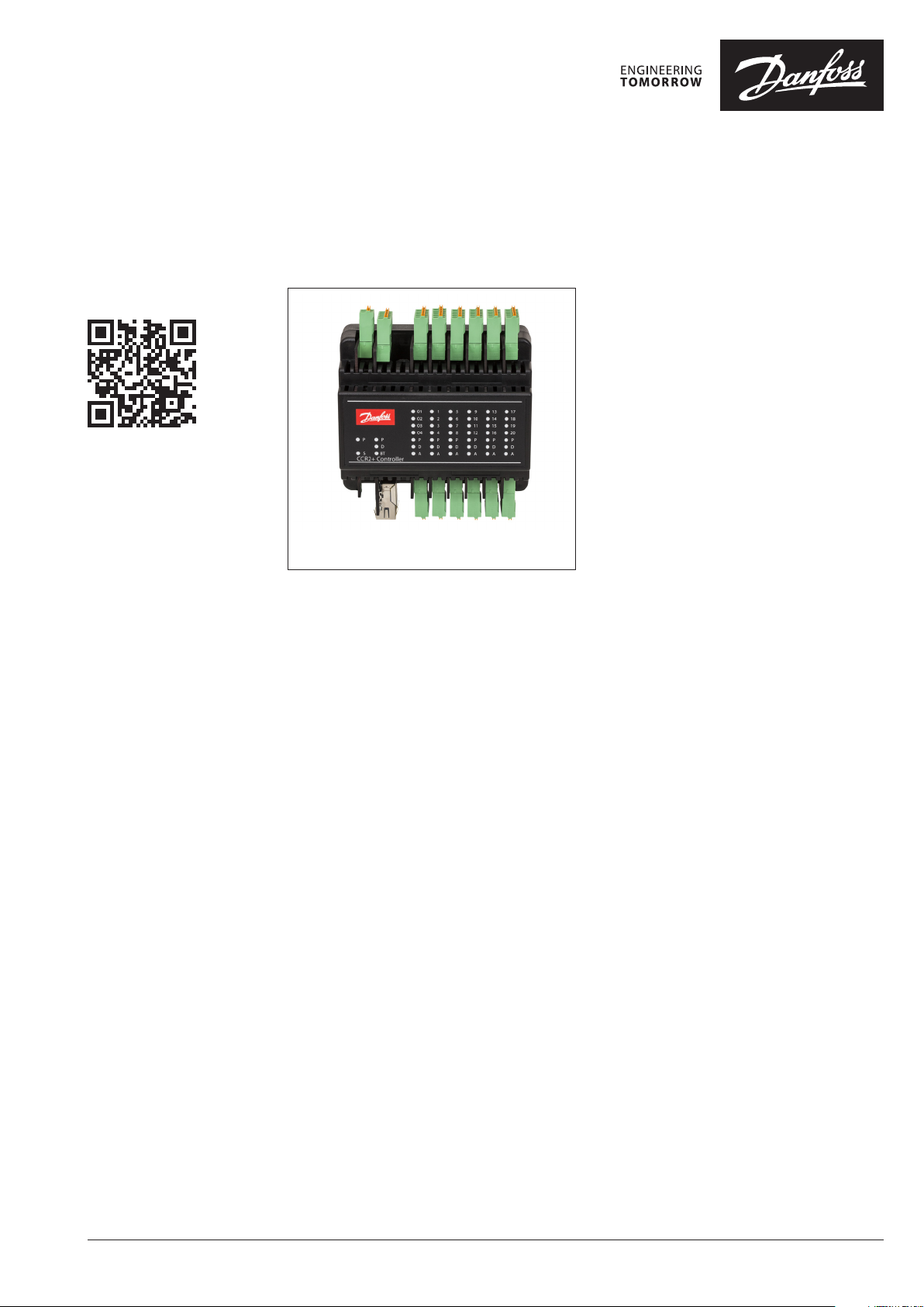
Fig. 1 CCR2+ Disinfection Process Control &
Temperature Registration
The CCR2+ is a controller used for optimising
the thermal disinfection process in hot water
systems with functions such as temperature
registration and/or monitoring circulation hot
water systems.
The CCR2+ can be applied independently, only
for temperature registration in circulation hot
water systems.
Thermal disinfection is one of the most effective
physical methods for bacteria pasteurisation
(Legionella pnemophila).
By optimising the thermal disinfection process,
the energy consumption and the disinfection
time are reduced.
By thermal disinfection the risk of bacteria
contamination in hot water systems can be
reduced significantly.
By temperature registration, the correct
temperature level in the hot water circulation
system can be controlled continuously and data
can be stored for later reference.
Disinfection temperature and time can be
adjusted:
• Disinfection temperatures from
50 °C to 78 °C;
• Disinfection time for the individual riser
within in the range: minimum to maximum.
Minimum required time is recommended
based on Brundrett resources and related to
temperature and is automatically limited by
producer. It cannot be adjusted below and
above the recommended values.
The CCR2+ incorporates LED status indicator,
build in Web-Server App, Wi-Fi connection and
LAN port, which allow the user to manually set
and monitor measured parameters from the
system on smart device or PC.
In addition, the CCR2+ also incorporates build in
memory to store temperature data.
The system monitoring function is based on
temperature registration and storage of data in
the memory.
The storage rate (frequency of temperature
sampling) can be adjusted by the user via the
CCR2+ settings menu.
Data can be copied and processed in excel files
(table, charts, graphs, etc.). All storage data are
recorded based on special algorithms, which
allow indication of genuine of stored data!
The sampling rate can be defined from the menu
within the range: minimum 1min. The sampling
rate has significant influence on period of data
storage.
From a technical point of view, the CCR2+
can control any number of risers due to the
possibility of parallel and sequence connections.
One unit of the CCR2+ can control 20 risers
equipped with thermo actuators type TWA-A
and PT1000 sensors (S1 … S20), plus one PT 1000
sensor (S0) in the supply pipe. The S0 sensor is
used for initiating the disinfection process (fig. 3)
or for registrating the supply temperature (Fig. 2)
(Fig. 4 wiring scheme: S0 input). The S0 sensor is
included in the package.
Additional functions:
• LED status indicators
• Build in web server for acess via mobile
devices or PC
• Alarm output;
• Pump protection function (cavitations in case
of closing all valves);
• Indication of state of disinfection process
realisation.
• System expansion via CCR+ Slave Unit
(+16 risers)
The CCR2+ power supply ~24 V (DC), 50 Hz and
output control of actuators 24 V.
Installation: on standard DIN relay.
Note: transformer is not included.
Recommended transformer: 150 VA, 24 V DC.
It is possible to connect CCR2+ to BMS system
via RS 485 in standard Fbus or ModBus RTU or IP
Modbus.
See the instructions for details.
© Danfoss | 2018.10 VD.D3.K1.02 | 1
Page 2
Data sheet Disinfection Process Control & Temperature Registration
1278910 19 20
CCR2+ System expansion
The system can also be expanded. For systems
up to 36 risers/loops CCR2+ system can be
expanded. With CCR+ Slave Unit, connected
to CCR2+ Controller (master), system can be
expanded with additional 16 risers/loops: 20
(CCR2+) + 16 (CCR+ Slave).
Very big systems (with more that 37) risers/loops
can be expanded with several CCR2+ Controlers
(with connected CCR+ Slave Unit on each
master), which are connected (see instructions):
• by parallel connection CCR2+ (with Slave Unit)
to another CCR2+ (with Slave Unit):
- with one S0 sensor or
- with individual S0 sensor for each CCR2+
(with Slave Unit);
• by sequence connection CCR2+ (with Slave
Unit) to another CCR2+ (with Slave Unit):
- with one S0 sensor or
- with individual S0 sensor for each CCR2+
(with Slave Unit).
This function offers control and registration of
temperatures in extensive installations with a
big number of risers, e.g.: installation with 108
risers/loops require 3 CCR2+ Controlers, with
connected CCR+ Slave Unit on each (3 x 20 + 3 x
16 = 108).
The type of combination after connection
(see instruction of CCR2+) should be selected
from the device menu settings. The correct
combination of connection allows optimatisation
of the total time required for the disinfection
process. For thermal disinfection CCR2+ can work
in two applications:
• As Independed control,
(S0 remote sensor connected)
No connection with heat source (boiler, substation, hot water tank, etc.)
Not fully automatic process. The total
disinfection time for the total installation
should be specified by maintenance service,
and after the disinfection process, the supply
temperature should be reduced manually to
comfort temperature.
• As Dependent control,
(S0 remote sensor connected and additional
connection with weather compensator (e.g.
ECL Comfort), boiler control or hot water
tank - in this case, thermal disinfection can be
performed in a fully automatic way. Moreover,
a second application is not required to specify
the total disinfection time for total installation
as the CCR2+ after finishing the thermal
disinfection in the last riser automatically
returns to comfort temperature by sending
signal (from output O3) to weather or boiler
control (free contact relay required).
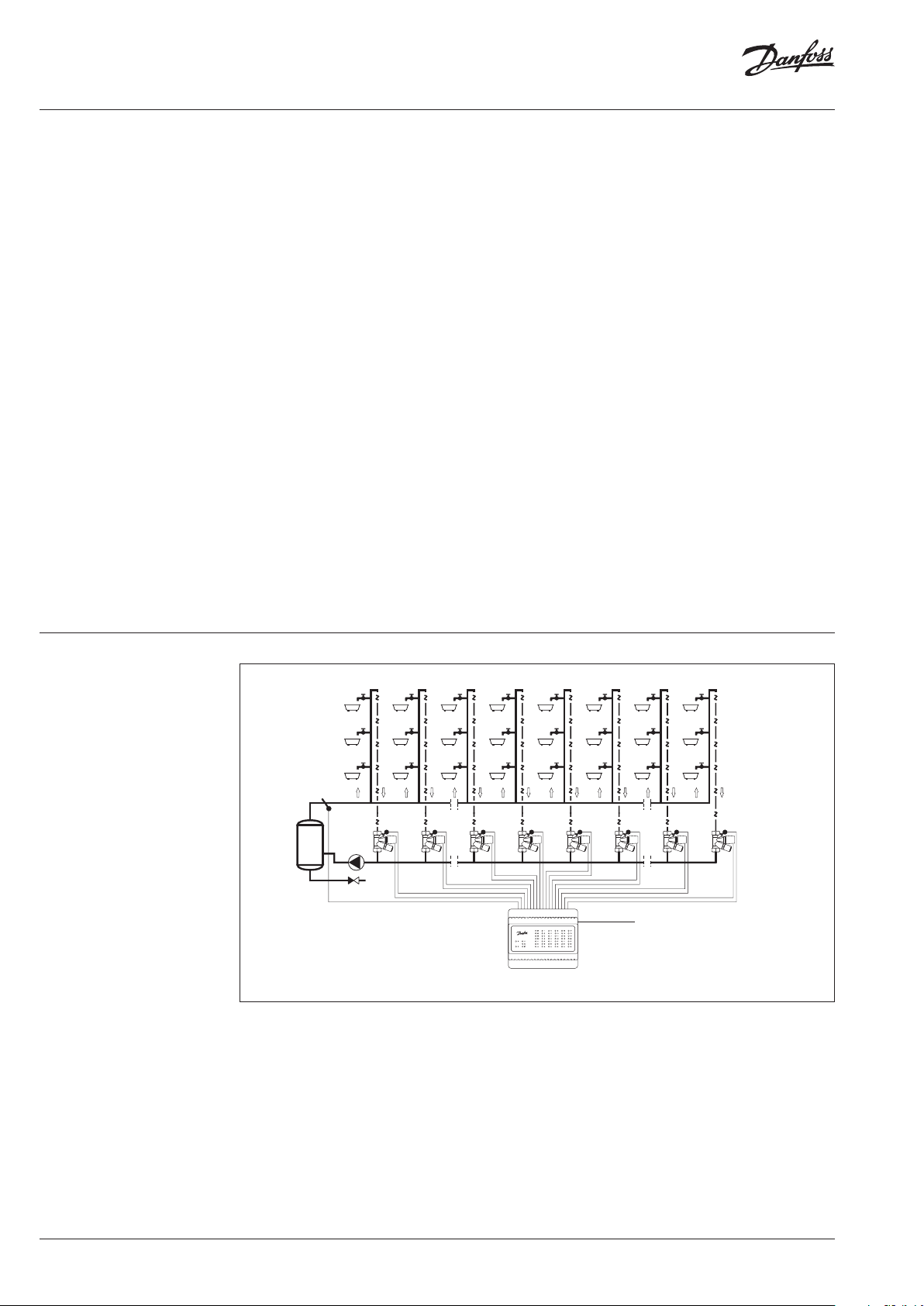
Applications
S0
Fig. 2 Scheme of installation for temperature registration independent system (only sensor S0 needed).
MTCV
S1
S2 S7 S8 S9 S10 S19 S20
V1
TWA
V2
TWA
MTCV MTCV MTCV MTCV MTCV MTCV MTCV
V7
TWA
V8
TWA
V9
TWA
24 VDC
V10
TWA
V19
TWA
V20
TWA
2 | VD.D3.K1.02 © Danfoss | 2018.10
Page 3
Data sheet Disinfection Process Control & Temperature Registration
1278910 19 20
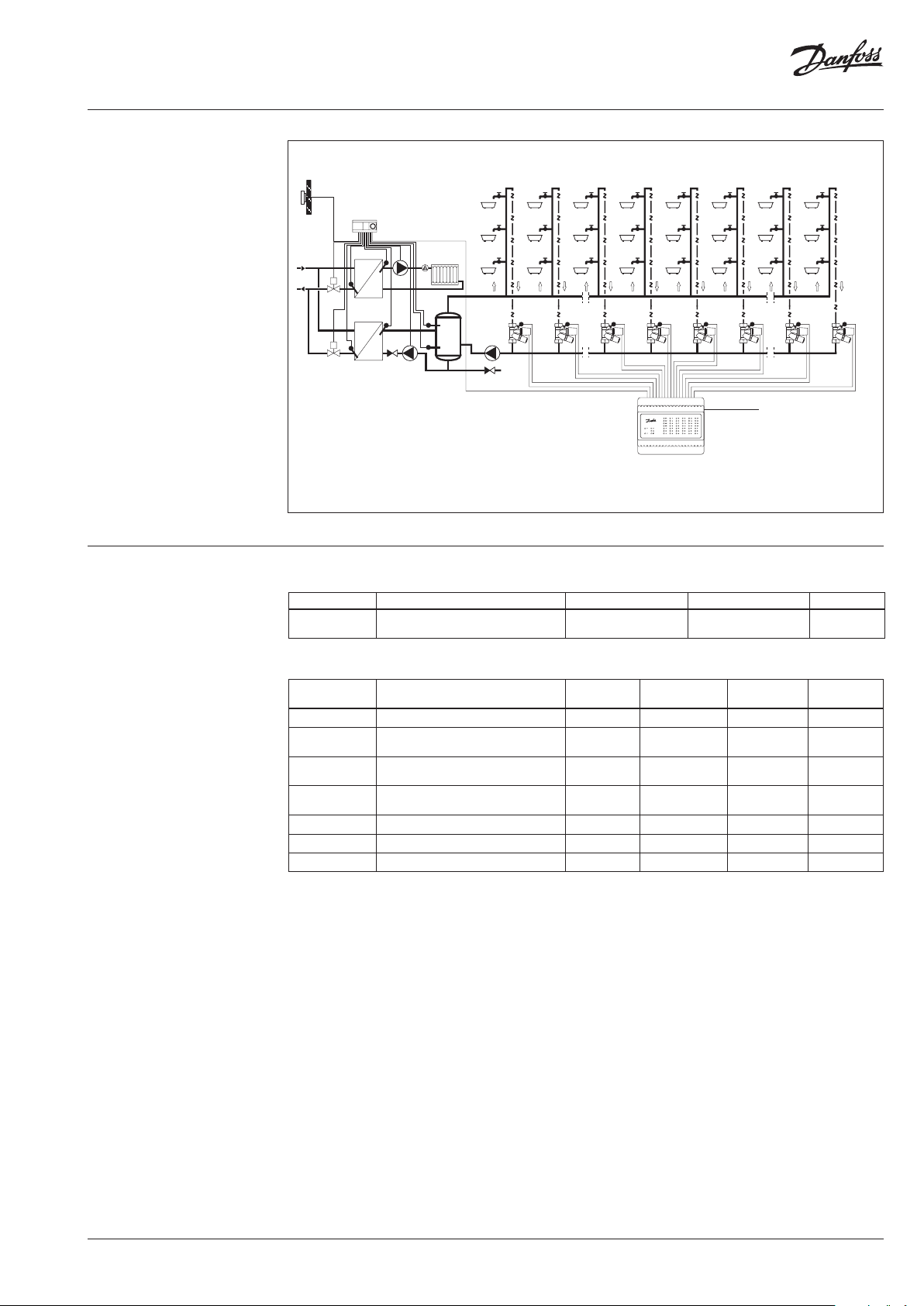
Applications (continuous)
ECL...
* ESMC s ensor S0 is includedwith CCR2+
Controller
Ordering
M
M
S
S
S1
S2
S7
S8
S9
S10
S19
S
S
S
S
V1
V2
V7
TWA
TWA
MTCV
MTCV MTCV MTCV MTCV MTCV MTCV
TWA
V8
TWA
V9
24 VDC
V10
TWA
TWA
S20
V19
TWA
MTCV
Fig. 3 Scheme of installation for disinfection and registration temperature
- dependent system (sensor S0 and connection to weather or another control needed)
Inclusive in the box CCR2+ Controller, 1 pcs ESMC sensor
Typ e Designation Supply voltage Actuator type/nos. Code No.
CCR2+ Controller
Disinfection Process Control
Temperature registration
24 V DC NC / 20 003 Z3851
Accessory
Typ e Designation
Voltage
(currentless)
Comments
TWA-A Thermal actuators 24 V NC VD.SA.P4.02 088H3110
TWA-A / ESMB
Adapter
Socket
Thermal actuators with
temperature sensors ESMB
Adapter for T WA-A actuators
for MTCV
Socket for temperature sensor to
MTCV
24 V NC VD.SA.P4.02 003 Z1043
-
for valve
DN15 / DN20
- for type ESMB VD.57.Y5.02 003Z102 4
ESMB Universal temperature sensor , PT1000 - with 2.5 m cable VD.74.I7.02 0 87B 1184
ESMC Surface Sensor, PT1000 - with 2 m cable VD.74.I7.02 08 7N 0011
CCR+ Slave Unit system expansion (add 16 risers) 24 V DC - - 003Z3852
Data she et
number
Code No.
VD.57.Y5.02 003 Z1022
V20
TWA
VD.D3.K1.02 | 3© Danfoss | 2018.10
Page 4

Data sheet Disinfection Process Control & Temperature Registration
Technical data
1)
To select proper p ower transformer
please follo w formula: 24 V 10VA
(controller) + 7 VA*/per each actuator
Temperature sensor (S0, S1-S20 / S21-36) Pt1000, S0- t ype ESMC / ESM11, S1 … S36 – type ESMB
Temperature range (registration) –20 °C … +120 °C
Measuring accuracy ± 0,1 K
Inputs: B1, B2 and B3 Free contact (5 V 1 mA)
Number of control valves (risers) 20 basic, additional 16 with system ex tension via CCR+ Slave Unit
Output signal to actuators 24 VDC max. 1 A
Alarm signal output 24 VDC max. 1 A
Relay output 0 … 24 DC max. 1 A
Type of memor y Build-In
Capacit y of memory 8 GB
Timer: Real time clock Built-in batter y - service life 10 years
- Wi-Fi (communication port only)
Communication interfaces
Default IP settings
Ambient temperature 0 … 50 °C
Transport temperature –10 … +60 °C
IP rating IP 20,
Power supply 24 VDC
Power consumption (Master controller only)
Power consumption (Slave Unit only)
Weight 0.3 kg
Installation DIN rail 35 mm
1)
- TPC/IP port (LAN cable connection)
- Modbus RS 485 RTU
- IP Modbus (L AN cable connection)
- Default L AN IP adress (static): 192.168.1.100
- Default WiFi acess IP adress (static): 192.168.1.10
- IP address mask: 255.255.255.0
- Gateway adress: 192.168.1.1
- DNS ad dress: 192 .168.1.1
- CCR name: ccrplus
- default password: admin1234
1)
10 VA
2 VA
Function After installation all settings should be carried
out on the CCR2+ according to the instructions in
the device settings menu. User need to connect
to CCR2+ with smarth device or PC.
Temperature registration
The CCR2+ can be used to record temperatures
in a hot water circulation system. Temperatures
are measured by PT 1000 temperature sensors
installed in MTCV valves. If the CCR2+ is used
solely for recording temperatures, it is not
necessary to install any actuators on the MTCV
valves.
Sampling time (data collection) intervals can
be adjusted using the control’s keypad from 1
minute.
Data are stored on internal memory. The data
collecting period depends strongly on and the
sampling interval.
Data are saved in *.csv format and can be
downloaded any time in Data menu.
The data can be visualised in spreadsheet and
graphs.
4 | VD.D3.K1.02 © Danfoss | 2018.10
Page 5

Data sheet Disinfection Process Control & Temperature Registration
The disinfecting procedure
• Start of disinfection
The start of the disinfection process
depends on the temperature signal from
the temperature sensor S0 installed on the
supply pipe of hot water systems or short cut
input B1 (Fig. 4, wiring).
The increased S0 temperature initiates
the thermal disinfection process when the
average long-term supply temperature
(from the last 5 minutes) exceeds the
set disinfection temperature. After the
disinfection process, the CCR2+ activates
all thermo actuators (TWA-A) that opens all
MTCV valves.
Start and progress of the disinfection process
are indicated on device setting menu.
It is possible to use outputs (Fig. 4) to indicate
any external operation of the disinfection
process, e.g.:
heat force,
alarm output.
• The thermal disinfection process
When the temperature of the circulation
water has achieved the set value (S1 … S20,
the disinfection temperature has to be
defined in device settings before the process
starts), the CCR2+ starts to countdown the
required disinfection time for each sensor
S1 … S20.
During the disinfection, the temperature in
the risers is controlled by MTCV + TWA-A
through control opening of MTCV by-pass,
temperature is kept on a constant level, above
(+1K) the minimum required disinfection
temperature.
Pulse Wide Modulation (PWM) functions
are used as TWA-A is thermo actuator. This
solution can provide a very stable regulation
with very low temperature oscillation.
Because the TWA-A is a thermal actuator,
its aperture is controlled by temporarily
switching the actuator on and off with
appropriate fill percentage (PWM-pulse wide
modulation).
If the temperature in the riser is too low, the
pulses switching the actuator on become
longer and the intervals become shorter. If
extending the switch-on pulses does not
result in increasing the temperature, they will
be extended even more, and the intervals
will be shortened, right up to the point where
constant voltage is fed to the actuator with no
intervals in the switched-on state.
If the temperature in the riser is too high, the
pulses switching the actuator on become
shorter and the gaps become longer. If
shortening the switch-on pulses does not
result in an reduction of the temperature,
the pulses will be shortened even more, and
the intervals will be lengthened, right up to
the point where the actuator is completely
switched off and the valve closed.
This procedure ensures that the riser is
protected from excessive and insufficient
temperatures, even though a two-state motor
is used. In order for the described process
to work correctly (without oscillation), its
dynamic parameters should be set in the
CCR2+ (integration time and disinfection
temperature control gain- PID control) or used
factory settings (adapted to thermal actuators
type TWA-A).
After the set time has elapsed, the CCR2+
shuts the disinfecting by-pass in the MTCV
valve for the given riser by switching the
TWA-A actuator off. Water flow in the riser
is now controlled solely by the thermostat
element in the MTCV valve.
The adopted procedure protects the riser
from overheating and reduces the risk of
corrosion or accidental burning and reduces
the overheating costs. Moreover, after
disconnecting the disinfected riser, the
water flow rate in the other risers increases,
accelerating the disinfection process for the
remaining installation.
The disinfection process progress is signalled
by outputs contacts O1,...,O4.. This solution
is applied where it is necessary to inform
the user that the disinfection process is in
progress, e.g. in buildings where it is executed
automatically (hotels, hospitals etc.).
• Problems during the disinfection process
A progress analysis is performed for the
entire system and for every single riser during
the disinfection process at set intervals (the
interval period is among other determined
among other by CCR2+ settings).
A list of risers is prepared based on the
temperature increase rate measurements for
each riser, sorted by the disinfection progress
amount. The average disinfection progress in
all risers is also calculated at this time.
If the average disinfection progress in all risers
is positive (better than that defined in the
settings), the process continues unchanged.
All risers are disinfected, and a subsequent
progress analysis is performed after the set
period.
If the measured progress of the temperature
increase is not positive (slower than defined
in the settings), it is highly probable that the
disinfection will fail. To ensure realisation,
the CCR2+ will (due to special algorithm)
divide the installation into smaller parts
and perform the process for selected risers.
Possible reasons for a non-positive process
can include excessive cooling of the branches,
an underrated pump and/or scaled pipes.
• Algorithm
If progress is insufficient after the interval
period, the CCR2+ divides the risers into two
groups. The first group includes half of the
risers with the best progress. (If there are an
VD.D3.K1.02 | 5© Danfoss | 2018.10
Page 6

Data sheet Disinfection Process Control & Temperature Registration
The disinfecting procedure
(continuous)
odd number of risers, the first group numbers
half of the risers plus one-half.)
The second group comprises the remaining
risers where progress is slow. These risera are
excluded from the disinfection process (the
riser valves are shut).
As a result of disconnecting the slow progress
risers, the pump’s delivery is directed to
a lower number of better risers, and the
possibility of a succesful completion of their
disinfection becomes higher.
After the next interval period, another
analysis of the disinfection progress is
performed, and the process is repeated.
If the progress in the operating risers is
positive, disinfection continues. As each of the
operating risers completes the disinfection,
its valve is shut, while the valve of the next
warmest riser yet to be disinfected is opened.
The number of risers disinfected concurrently
is constant.
If progress is still insufficient, the risers are
again divided into a good half and a bad half,
where the latter is disconnected.
In the worst case scenario, following the last
split, disinfection will be performed in one
riser only and upon its completion the next
riser will be served. If even then the progress
is not satisfactory, it could mean any of the
following. The supply temperature is too low,
hydraulic losses are too high, the pump’s
delivery rate or head is too small.
By applying suitable algorithms, the CCR2+
makes it possible to execute a disinfection
process using the existing circulation pump
even in the most adverse thermal conditions.
• End of the thermal disinfection process
When the disinfection process is finished, the
by-pass at the MTCV is closed.
The LED status indicator and Reading Menu in
App indicates “process successful”.
It is possible to use outputs (Fig. 4) to indicate
any external operation of the disinfection
process, e.g.: Disinfection finished.
If the progress of the process is not positive
(it is not possible to achieve required
disinfection temperature even in a single
riser, above-mentioned problems), the
CCR2+ will stop the process. When the
CCR2+ operates in applications as dependent
control – a signal to the weather compensator
or another boiler control is sent, and the
installation automatically returns to the
comfort temperature. When CCR2+ operates
as independent control, the maintenance
service should reduce the supply temperature
after the signal about turn-off the process.
Upon completing disinfection in the last riser,
the CCR2+ opens O1 output (Heat Force);
and closes O3 output (Dissinfection finished),
signalling that the process is finished. The
main control (in boiler station or sub-station)
automatically reduces the supply temperature
to return to comfort temperature level.
These signals from the CCR2+ are applied to
return to the comfort temperature, when:
• Disinfection process is successful;
• When no progress during the process.
If the supply temperature does not fall (due to
some errors), the CCR2+ initially opens the bypass on the MTCV to achieve a certain flow in
the installation (pump protection function).
• Pump protection against cavitations
When the disinfection process is finished,
the CCR2+ keeps all disinfections, the
by-pass is closed. In case of not reduced
flow temperature after the disinfection
process, the CCR+ runs the pump protection
function. The first valve remains open until
the temperature on the sensor S0 returns
to the normal circulation temperature or
ECL (or other electronic control) opens O1
output (Heat Force) and closes O3 output
(Dissinfection finished).
• Troubleshooting
Disinfection will not be completed if:
- Too low supply temperature in the
circulation system;
- Temperature during the disinfection
process was maintained shorter then preset (e.g., the electronic control reduced
the temperature before the process was
finished);
- The flow in the riser was not sufficient. (e.g.
scale in the pipe …);
- Any errors in the disinfection process are
indicated in the CCR2+ Menu Readings;
- Analyses of the process have to be made.
Disinfection will be aborted by the CCR2+
control if:
- Disinfecting temperature is not attained in
any one of the risers during disinfection, e.g.
the hot water temperature is lowered before
the process is completed;
- The hot water supply temperature measured
by sensor S0 drops below the disinfecting
temperature before disinfection in the risers
is completed;
- Disinfection remains incomplete after 260
minutes;
- In each case of aborting the disinfection
process the control indicates which risers
were not disinfected successfully on CCR2+
Menu Readings.
Disinfection may fail for the entire
installation of only for selected risers.
Failed disinfection is reported by the CCR2+:
- On its App (Menu Readings);
- LED status indicators
- O4 ouput closes (Alarm)
- BMS statuses
6 | VD.D3.K1.02 © Danfoss | 2018.10
Page 7

Data sheet Disinfection Process Control & Temperature Registration
The disinfecting procedure
(continuous)
• Recommendation
Before starting the thermal disinfection
process, please contact your local legislation
institution about local regulation and
requirements.
Perform water tests for Legionella
pneumophila bacteria detection to achieve
information about bacteria concentration and
genus of bacteria as some colonies require
higher pasteurisation temperatures.
A successful thermal disinfection process
depends on many elements (good pipe
insulation, possibility to reach high supply
temperature, good pipe condition- no scale
inside), it is therefore recommended to:
- Start the process from lower required
disinfection temperatures – if the process is
successful try to increase the temperature as
the pasteurisation process is much faster at
higher temperatures;
- Increase the temperature of the process
step by step (e.g. every two degrees)
remember that a higher demand for thermal
disinfection requires a higher supply
temperature (what in many cases can be
limited due to technical problems with heat
sources).
Remember that high temperatures in the
system can scald users and increase the risk of
precipitation lime deposit.
After two – three processes of thermal
disinfections make a water test for bacteria. If
correctly performed, the thermal disinfection
process results will be visible immediately.
• Comments
The Danfoss solution based on electronic
controls (MTCV-C + CCR2+ + TVM-W) of
the thermal disinfection process allows for
maintenance of an appropriate circulation
temperature in the systems simultaneously
with recognising thermal disinfections
in minimum time (for all installations automatically) and reducing scalding (TVM-W)
and precipitation of deposit problems.
The system is designed to provide maximum
guarantee of thermal disinfection, while at the
same time considering the cost aspect!
CCR2+ settings
Temperature set in the circulation risers and disinfection time:
Temperature
of disinfection
(°C)
50 6 h 20 minute 7 h 30minute
51 6 h 10 minute 7 h 20 minute
52 4 h 00 minute 5 h 50 minute
53 2 h 00 minute 4 h 00 minute
54 1 h 00 minute 2 h 00 minute
55 0 h 50 minute 2 h 00 minute
56 0 h 40 minute 1 h 20 minute
57 0 h 20 minute 1 h 00 minute
58 0 h 15 minute 0 h 50 minute
59 0 h 15 minute 0 h 45 minute
60 0 h 14 minute 0 h 40 minute
61 0 h 13 minute 0 h 35 minute
62 0 h 12 minute 0 h 30 minute
63 0 h 12 minute 0 h 28 minute
64 0 h 11 minute 0 h 27 minute
65 0 h 11 minute 0 h 26 minute
Time setting for thermal disinfection
in: hour … Minute …
Minimum required
Maximum
recommended
Temperature
of disinfection
Time setting for thermal disinfection
in: hour … Minute …
(°C)
66 0 h 10 minute 0 h 25 minute
67 0 h 9 minute 0 h 25 minute
68 0 h 8 minute 0 h 22 minute
69 0 h 7 minute 0 h 21 minute
70 0 h 6 minute 0 h 20 minute
71 0 h 6 minute 0 h 18 minute
72 0 h 6 minute 0 h 14 minute
73 0 h 5 minute 0 h 12 minute
74 0 h 4 minute 0 h 10 minute
75 0 h 3 minute 0 h 10 minute
76 0 h 3 minute 0 h 10 minute
77 0 h 2 minute 0 h 9 minute
78 0 h 2 minute 0 h 8 minute
79 0 h 2 minute 0 h 6 minute
80 0 h 2 minute 0 h 6 minute
Minimum required
Maximum
recommended
VD.D3.K1.02 | 7© Danfoss | 2018.10
Page 8
Data sheet Disinfection Process Control & Temperature Registration
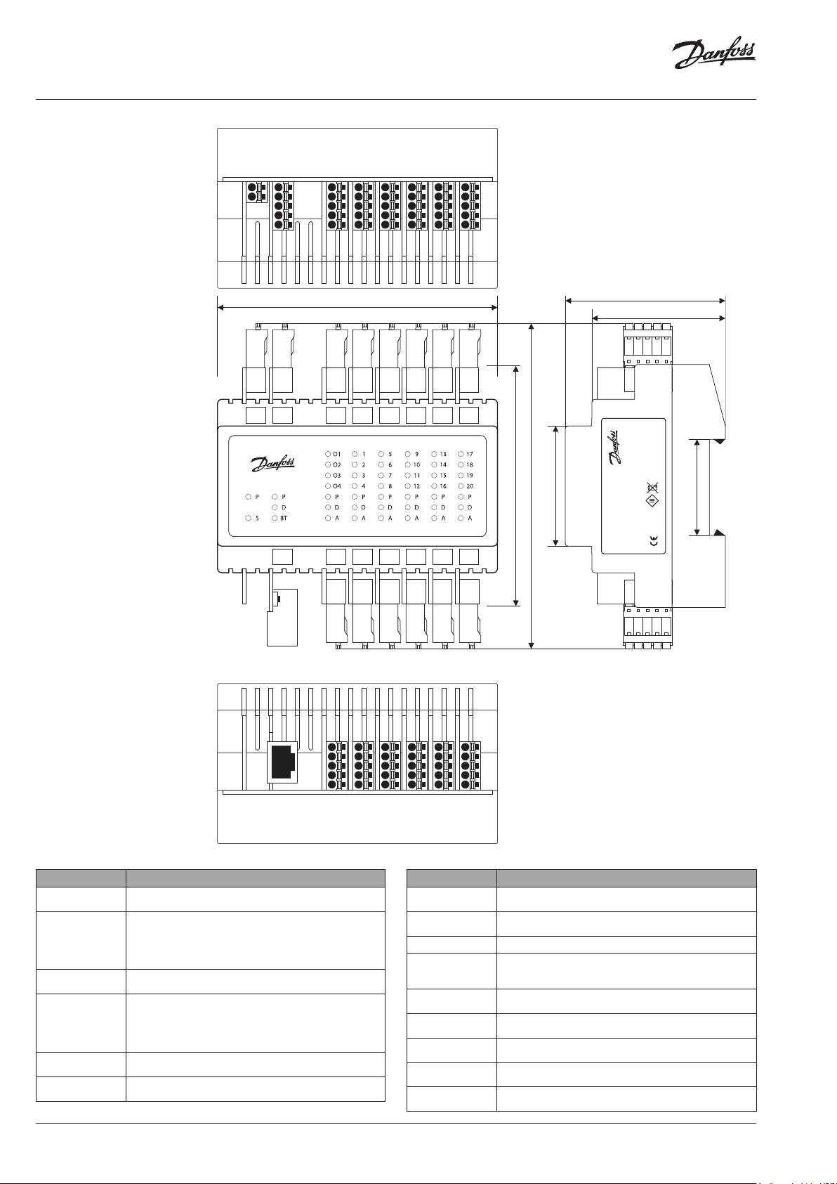
Wiring, Dimensions and
Installation
G
G
Lbus
24VDC
G
B
A
POWER
Master
LBus
0V
RS485
24VDC
CCR2+ Controller
TCP/IP
LAN
C
CCCCC
O4
V4
V8
V12
0
O3
V3
O2
O1
Module
V7
V2 V6 V10 V14 V18
V1
V5
Module 1
Module 2
V16
4
V11
V15
V9
V13
Module 3
Module
105 mm
C
O1-4
B1-B3 S0
G
V5-8CV9-12
V1- 4
S5-8 S9-12
S1-4
GGGGG
C
C
V13-16
S13-16
C
V20
5
V19
V17
Module
C
V17-20
S17-20
90 mm
122 mm
45 mm
Disinfection
60 mm
MADE IN POLAND
CCR2+
Process Controller
50 mm
20171213V2.40
003Z3851
Supply 24VDC
Danfoss A/S
6430 Nordborg, Denmark
36 mm
RoHS
Fig. 4 Wiring sheme - CCR+
Master Controller
Connector/port Description
0V
24VDC
Lbus
RS485
C
O1,.. ,O4
C
V1-4
C
V5-8
C
V9 -12
0V – ground (-) power supply
24 V DC(+) power supply
G – ground Lbus port (for system expansion)
Lbus – Lbus por t (for system expansion)
G – ground (Modbus RS 485)
B – port B (Modbus RS 485)
A - port A (Modbus RS 485)
C – common port dedicated to ouputs O1-O4
O1,.. O4 – defined outputs
C – common port dedicated to actuators V1-4
O1 - output: Heat Force
O2 - output: Start next CCR/Slave Unit
O3 - output: Dissinfection finished
O4 - output: Alarm
C – common port dedicated to actuators V5- 8
V5. .V8 – outputs to ac tuators
C – common port dedicated to actuators V9 -12
V9. .V12 – outputs to actuators
TCP/IP
RJ45
4
B1
TCP/IP
Master
POWER
RJ45
S2
B2
S3
B3
Module 1
Module 0
S4
S0
G
G
S10
S6
S11
S7
Module 2
Module
S12
S8
G
G
3
S9
S5
S1
S13
S14
S15
Module
S16
G
S17
S18
S19
Module 5
S20
G
Connector/port Description
C
V13 -16
C
V17-2 0
C – common port dedicated to actuators V13-16
V13..V16 – outputs to actuators
C – common port dedicated to actuators V17-20
V17.. V2 0 – outputs to ac tuators
TC P/IP, L AN TCP/IP port or IP Modbus port
B1-3, S0
G
S1-4
G
S5-8
G
S9 -12
G
S13 -16
G
S17-2 0
G
B1,B2, B3 defined inputs
S0 – temp. sensor
G – common ground dedicated to inputs/sensor
S1.. S4 – inputs from sensors
G – common ground dedicated to sensor S1-4
S5..S8 – inputs from sensors
G – common ground dedicated to sensors S5-8
S9. .S12 – inputs from sensors
G – common ground dedicated to sensors S9-12
S13.. S16 – inputs from sensors
G – common ground dedicated to sensors S13-16
S17. .S 20 – inputs from sensors
G – common ground dedicated to sensors S17-20
8 | VD.D3.K1.02 © Danfoss | 2018.10
Page 9

Data sheet Disinfection Process Control & Temperature Registration
Thermal actuator
TWA-A
Descriptions The thermal actuator TWA-A is for use with the
MTCV and small Danfoss seated valves.
The actuator starts to move:
- when the signal is applied.
Ordering
Technical data
Electrical connection and
mounting
Typ e
TWA-A
TWA-A
Supply voltage 24 V AC/DC +30% to –15% 230 V AC. +10% to –15%
Frequency 50 - 60 Hz
Average power consumption 2 W
Spindle travel time (Danfoss valves) 3 minutes
Ambient temperature 0 - 60 °C
Enclosure IP 41
Cable length 120 0 mm
Max. spindle travel 3 mm
Voltage
(currentless)
230 V~ NC 088H3112
24 V NC 088H3110
Valve
function
Code No.
Blue/Brown
Blue/Brown Green/Green
VD.D3.K1.02 | 9© Danfoss | 2018.10
Page 10

Data sheet Disinfection Process Control & Temperature Registration
Dimensions
Internal
thread
DN 15
DN 20
A
IS O 7/1aIS O 7/1H(mm)H1(mm)L(mm)L1(mm)
Rp ¾ Rp ½ 79 129 75 220 0,55
Rp 1 Rp ¾ 92 129 80 240 0,60
Weight
(kg)
Code No.
00 3Z4515
003Z4520
10 | VD.D3.K1.02 © Danfoss | 2018.10
Page 11
Data sheet Disinfection Process Control & Temperature Registration
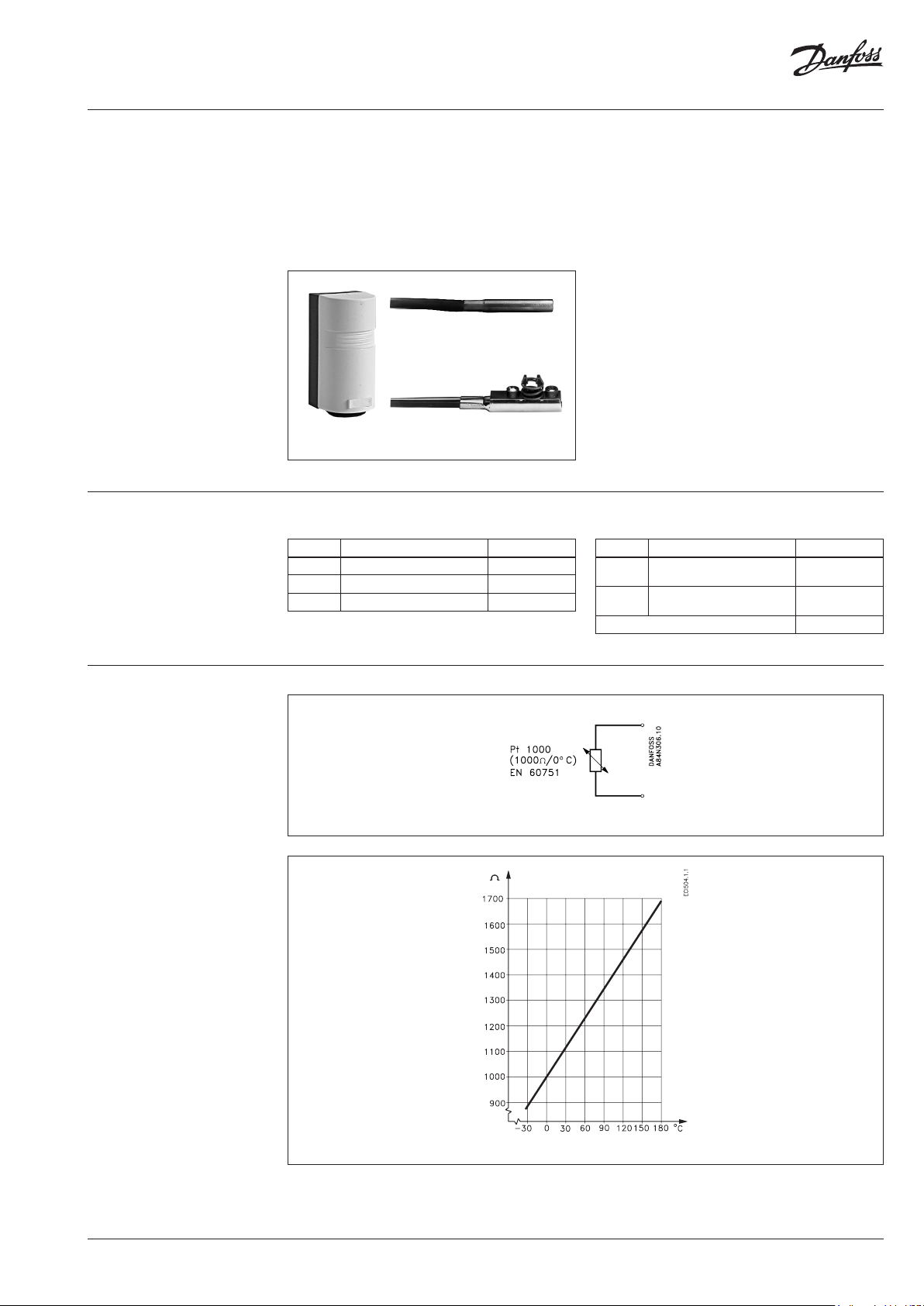
Temperature sensors (Pt 1000)
ESM-11, ESMB, ESMC
Application
Ordering
Wiring
ESMB
ESM -11
ESMC
Temperature sensors
Typ e Designation Code No.
ESM -11 Surface sensor 0 87B 1165
ESMB Universal sensor 0 87B118 4
ESMC Surface sensor 08 7N 0011
- Platinum-based sensors, 1000 W at 0 °C
All the temperature sensors are two-wire devices,
and all connections are inter-changeable.
The surface sensor type ESM-11 has a spring
contact surface to ensure a good heat transfer in
pipes of all sizes.
The basic sensor contains a platinum element
with a characteristic that complies with EN 60751.
Accessories and spare parts
Typ e Designation Code No.
Pocket
Pocket
Heat conduc ting paste, 3.5 cm
Immersion, stainless steel 100
mm, for ESMB (0 87B118 4)
Immersion, stainless steel 250
mm, for ESMB (0 87B118 4)
3
084N1082
084N1083
04 1E0110
Connection cable: 2 × 0.4 - 1.5 mm
Resistance characteristics
2
VD.D3.K1.02 | 11© Danfoss | 2018.10
Page 12

Danfos
produc
Al
Danfoss A/S
Heating Segment
Data sheet Disinfection Process Control & Temperature Registration
Technical data
All temperature sensors contain a Pt 1000 element. Instructions are supplied with the products.
Typ e
ESM -11
ESMB
ESMC
Pocket
Materials
Electrical
connection
Mounting
× = PE (polyethylene) bag
×× = Cardboard
Sensor characteristics Referri ng to EN 60751, Class 2 B Max. deviation 2 K
Time constants
Temperature range Enclosure Time constant PN
0 … 100 °C IP 32 3 s -
0 … 100 °C IP 54 20 s -
0 … 100 °C IP 54 10 s -
0 … 200 °C - See “Data specific” 25
Packing
ESM -11
ESMB
ESMC
Cover: ABS ××
Base: PC (polycarbonate)
Encapsulation: 18/8 stainless steel ×
Cable: 2.5 m, PVC, 2 × 0.2 mm
2
Encapsulation: Top part: nyrol, bottom part: nickel coated Cu ×
Cable: 2 m, PVC, 2 × 0.2 mm
2
Pocket Tube and body: AISI 316
ESM -11 Terminal block for 2 wires in base part
ESMB 2-wire cable (2 × 0.2 mm2)
ESMC 2-wire cable (2 × 0.2 mm2)
ESM-11/ESMC Clamp for tube DN 15-65 supplied
ESMB For pipe or flat surface or in pocket
Pocket G ⁄ A
ESMU (Cu) in pocket
ESMB in pocket
32 s (in water)
160 s (in air)
20 s (in water)
140 s (in air)
Dimensions
s can accept no responsibility for possible errors in catalogues, brochures and o ther printed material. Danfoss reserves the right to alter its pro ducts without notice. This also applies to
ts already on order provided that such alterations can be m ade without subsequential changes being necessary in specications already agreed.
l trademarks in this material are property of the r espective companies. Danfoss and all Danfoss l ogotypes are trademarks of Danfoss A/S. All rights reserve d.
ESM -11
pocket for ESMB
• heating.danfoss.com • +45 7488 2222 • E-Mail: heating@danfoss.com
ESMC
ESMB
© Danfoss | DHS-SRMT/SI | 2018.1012 | VD.D3.K1.02
 Loading...