

Page 1
Installation Guide
CCR2 Disinfection Process Control & Temperature Registration
CCR2 - CONTROLLER
ENGLISH
POLSKI
DANSK
ČESKY
DEUTSCH
CCR2 Disinfection Process Control & Temperature Registration www.danfoss.com Page 5
CCR2 Sterownik dezynfekcji z rejestratorem temperatur www.danfoss.pl Strona 17
CCR2 - desinfektionsprocesregulator & temperaturmåling www.danfoss.dk Seite 29
CCR2 Řízení dezinfekčního procesu se záznamem teploty www.danfoss.cz Strana 41
Elektronischer Zirkulationsregler Typ CCR2 zur thermischen
Desinfektion und Datenprotokollierung
www.danfosswaermeautomatik.de
Seite 53
Multilingual CCR2 instructions are provided on SD card included in CCR2 package or on http://www.danfoss.com
Heating Solutions VI.D1.E2.1R SMT/SI
1
Page 2
Installation Guide CCR2
CCR2 - CONTROLLER
CCR2 - CONTROLLER
Fig. 1 CCR2 & ESMC
Fig. 3a
Fig. 2
CCR2 - CONTROLLER
CCR2 - CONTROLLER
Fig. 3b
2
SMT/SI VI.D1.E2.1R Heating Solutions
Page 3

Supplay voltage
temperature sensors
outlet: actuators 1 … 8
90 mm
Installation Guide CCR2
Supplay voltage
temperature sensors
outlet: actuators 1 … 8
RS 485
CCR
CCR
Triac output
C
V2 V3 V4 V5 V6 V7 V8
V1
S1 … S8
M S1 S2 S3 S4 S5 S6 S7 S8
CCR
CCR
temp.
sensor
dezyn.
S0
M B1 M B2 M M A
S0 B
RS 485
start
stop
Fbus
dezyn.
ModBus
do BMS
C
V1 V2 V3 V4 V5 V6 V7 V8
158.5 mm
M S1 S2 S3 S4 S5 S6 S7 S8 M B1 M B2 M M AS0 B
Fig. 4 Wiring
CCR2
CONTROLLER
V13
V10 V9
C
outlet: actuators 9 … 16
Triac output
V11 V12
V15 V16
V14
M S9 S10 S11 S12 S13 S14 S15 S16
temperature sensors
S9 … S16
CCR2 - CONTROLLER
SD
FLASH
CARD
NO T1
C
NC
To ECL force
signal for
disinfection
Relay switch output
To next CCR 2
for parallel or
sequence connection
Transistor output
0V 0V 24V
T2
ALARM
24 VAC
158.5mm
Do not install or
remove SD card when
connected to the
current.
CCR2 - CONTROLLER
V13
V10V9
V15 V16
V11 V12
C M S9 S10 S11 S12 S13 S14 S15 S16
V14
58 mm
31 mm
10
90 mm
35 mm
90 mm
C
35 mm
62 mm
NO T1T20V 0V 24V
NC
Fig. 5 Dime nsions and installations on DIN re lay 35 mm
temp.
start
stop
dezyn.
Fbus
ModBus
do BMS
Triac output
C
V2 V3 V4 V5 V6 V7 V8
V1
S1 … S8
M S1 S2 S3 S4 S5 S6 S7 S8
sensor
dezyn.
S0
M B1 M B2 M M A
S0 B
CCR2
CONTROLLER
V13
V10 V9
C
outlet: actuators 9 … 16
Triac output
Fig. 6 CCR2 connec tion to ECL
Heating Solutions VI.D1.E2.1R SMT/SI
V11 V12
V15 V16
V14
M S9 S10 S11 S12 S13 S14 S15 S16
temperature sensors
S9 … S16
C
NC
1 2 3
ECA9010
ECL XXX
NO T1
To next
CCR 2 for
parallel or
sequence
connection
Transistor output
T2
ALARM
0V 0V 24V
24 VAC
33
Page 4
Installation Guide CCR2
C
V1
V2 V3 V4 V5 V6 V7 V8
CCR2
V10V9
V11 V12
C
C
V1
V2 V3 V4 V5 V6 V7 V8
CCR2
V10V9
V11 V12
C
C
V1
V2 V3 V4 V5 V6 V7 V8
CCR2
V10V9
V11 V12
C
C
V2 V3 V4 V5 V6 V7 V8
V1
CCR2
V10V9
V11 V12
C
C
V2 V3 V4 V5 V6 V7 V8
V1
CCR2
V10V9
V11 V12
C
V13
V15 V16
V14
V13
V15 V16
V14
V13
V15 V16
V14
V13
V15 V16
V14
V13
V15 V16
V14
M S1 S2 S3 S4 S5 S6 S7 S8
This is Master; CCR Sys: Sequence
StartDis: S0 or S0 + PRG
M S9 S10 S11 S12 S13 S14 S15 S16
M S1 S2 S3 S4 S5 S6 S7 S8
This is Slave;
M S9 S10 S11 S12 S13 S14 S15 S16
M S1 S2 S3 S4 S5 S6 S7 S8
M S9 S10 S11 S12 S13 S14 S15 S16
M S1 S2 S3 S4 S5 S6 S7 S8
M S9 S10 S11 S12 S13 S14 S15 S16
M S1 S2 S3 S4 S5 S6 S7 S8
M S9 S10 S11 S12 S13 S14 S15 S16
StartDis: B1
This is Slave; CCR Sys: Sequence
StartDis: B1
This is Slave; CCR Sys: Sequence
StartDis: B1
This is Slave; CCR Sys: Sequence
StartDis: B1
TEMP.S0
M B1 M B2 M M A
S0 B
NO T1T20V 0V 24V
C
NC
1 2 3
ECA9010ECL XXX
M B1 M B2 M M A
S0 B
CCR Sys: Sequence
NO T1T20V 0V 24V
C
NC
M B1 M B2 M M A
S0 B
NO T1T20V 0V 24V
C
NC
M B1 M B2 M M A
S0 B
NO T1T20V 0V 24V
C
NC
M B1 M B2 M M A
S0 B
NO T1T20V 0V 24V
C
NC
C
V1
V2 V3 V4 V5 V6 V7 V8
CCR2
V10V9
V11 V12
C
C
V1
V2 V3 V4 V5 V6 V7 V8
CCR2
V10V9
V11 V12
C
C
V1
V2 V3 V4 V5 V6 V7 V8
CCR2
V10V9
V11 V12
C
C
V2 V3 V4 V5 V6 V7 V8
V1
CCR2
V10V9
V11 V12
C
C
V2 V3 V4 V5 V6 V7 V8
V1
CCR2
V10V9
V11 V12
C
V13
V15 V16
V14
V13
V15 V16
V14
V13
V15 V16
V14
V13
V15 V16
V14
V13
V15 V16
V14
M S1 S2 S3 S4 S5 S6 S7 S8
This is Master; CCR Sys: Sequence
StartDis: S0 or S0 + PRG
M S9 S10 S11 S12 S13 S14 S15 S16
M S1 S2 S3 S4 S5 S6 S7 S8
This is Slave;
M S9 S10 S11 S12 S13 S14 S15 S16
M S1 S2 S3 S4 S5 S6 S7 S8
M S9 S10 S11 S12 S13 S14 S15 S16
M S1 S2 S3 S4 S5 S6 S7 S8
M S9 S10 S11 S12 S13 S14 S15 S16
M S1 S2 S3 S4 S5 S6 S7 S8
M S9 S10 S11 S12 S13 S14 S15 S16
StartDis: S0 + B1
This is Slave; CCR Sys: Sequence
StartDis: S0 + B1
This is Slave; CCR Sys: Sequence
StartDis: S0 + B1
This is Slave; CCR Sys: Sequence
StartDis: S0 + B1
TEMP.S0
M B1 M B2 M M A
S0 B
NO T1T20V 0V 24V
C
NC
1 2 3
ECA9010ECL XXX
TEMP.S0
M B1 M B2 M M A
S0 B
CCR Sys: Sequence
NO T1T20V 0V 24V
C
NC
TEMP.S0
M B1 M B2 M M A
S0 B
NO T1T20V 0V 24V
C
NC
TEMP.S0
M B1 M B2 M M A
S0 B
NO T1T20V 0V 24V
C
NC
TEMP.S0
M B1 M B2 M M A
S0 B
NO T1T20V 0V 24V
C
NC
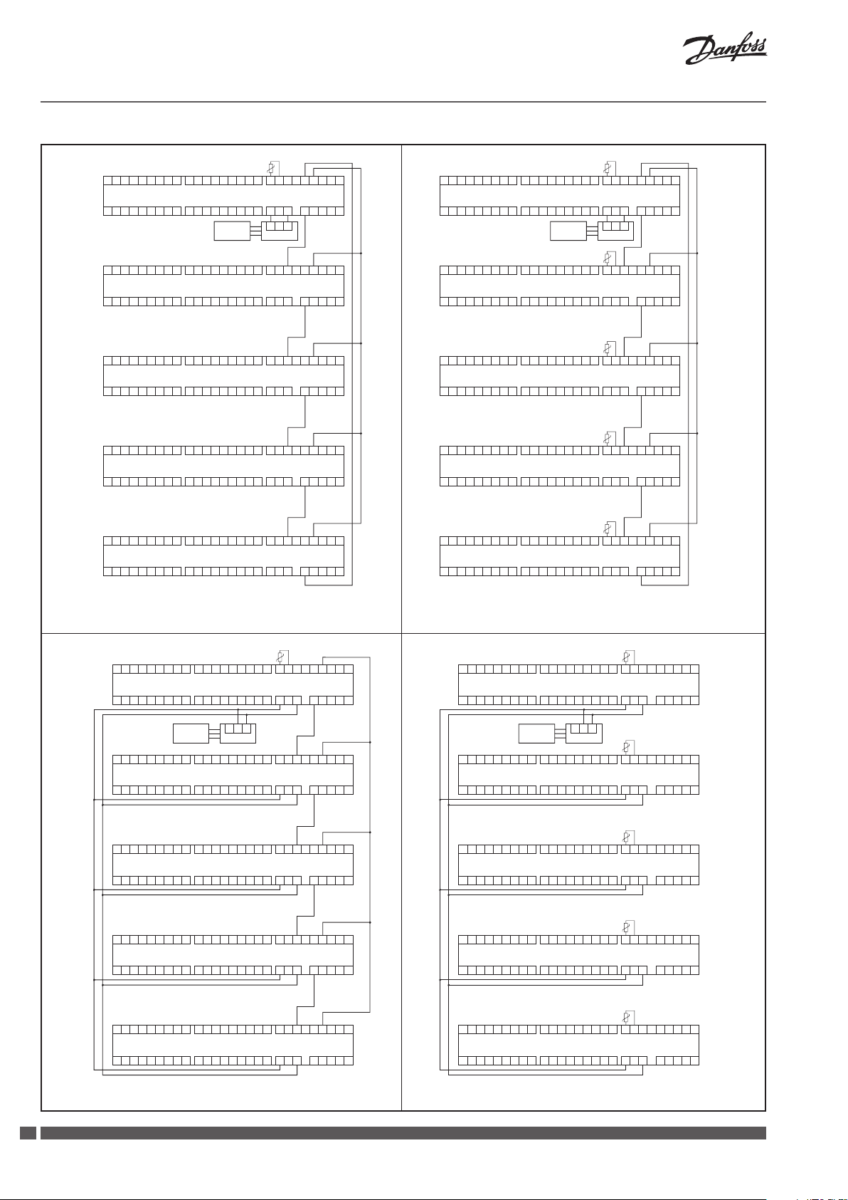
Fig. 7 CCR2 connec tion to CCR2: sequences connection w ith one S0 sensor
TEMP.S0
C
V1
V2 V3 V4 V5 V6 V7 V8
CCR2
V10V9
V11 V12
C
C
V1
V2 V3 V4 V5 V6 V7 V8
CCR2
V10V9
V11 V12
C
C
V1
V2 V3 V4 V5 V6 V7 V8
CCR2
V10V9
V11 V12
C
C
V1
V2 V3 V4 V5 V6 V7 V8
CCR2
V10V9
V11 V12
C
C
V1
V2 V3 V4 V5 V6 V7 V8
CCR2
V10V9
V11 V12
C
V13
V15 V16
V14
V13
V15 V16
V14
V13
V15 V16
V14
V13
V15 V16
V14
V13
V15 V16
V14
M S1 S2 S3 S4 S5 S6 S7 S8
This is Master; CCR Sys: Paralell
StartDis:
M S9 S10 S11 S12 S13 S14 S15 S16
1 2 3
ECA9010ECL XXX
M S1 S2 S3 S4 S5 S6 S7 S8
This is Slave;
M S9 S10 S11 S12 S13 S14 S15 S16
M S1 S2 S3 S4 S5 S6 S7 S8
This is Slave; CCR Sys: Paralell
M S9 S10 S11 S12 S13 S14 S15 S16
M S1 S2 S3 S4 S5 S6 S7 S8
This is Slave; CCR Sys: Paralell
M S9 S10 S11 S12 S13 S14 S15 S16
M S1 S2 S3 S4 S5 S6 S7 S8
This is Slave; CCR Sys: Paralell
M S9 S10 S11 S12 S13 S14 S15 S16
M B1 M B2 M M A
S0 B
S0 or S0 + PRG
C
NC
M B1 M B2 M M A
S0 B
CCR Sys: Paralell
StartDis: B1
C
NC
M B1 M B2 M M A
S0 B
StartDis: B1
C
NC
M B1 M B2 M M A
S0 B
StartDis: B1
C
NC
M B1 M B2 M M A
S0 B
StartDis: B1
C
NC
NO T1T20V 0V 24V
NO T1T20V 0V 24V
NO T1T20V 0V 24V
NO T1T20V 0V 24V
NO T1T20V 0V 24V
Fig. 8 CCR2 connec tion to CCR2: sequences connection w ith individual
S0 sensor
TEMP.S0
C
V1
V2 V3 V4 V5 V6 V7 V8
CCR2
V10V9
V11 V12
C
C
V1
V2 V3 V4 V5 V6 V7 V8
CCR2
V10V9
V11 V12
C
C
V1
V2 V3 V4 V5 V6 V7 V8
CCR2
V10V9
V11 V12
C
C
V1
V2 V3 V4 V5 V6 V7 V8
CCR2
V10V9
V11 V12
C
C
V1
V2 V3 V4 V5 V6 V7 V8
CCR2
V10V9
V11 V12
C
V13
V15 V16
V14
V13
V15 V16
V14
V13
V15 V16
V14
V13
V15 V16
V14
V13
V15 V16
V14
M S1 S2 S3 S4 S5 S6 S7 S8
This is Slave; CCR Sys: Paralell
StartDis:
M S9 S10 S11 S12 S13 S14 S15 S16
1 2 3
ECA9010ECL XXX
M S1 S2 S3 S4 S5 S6 S7 S8
This is Slave;
StartDis: S0 or S0 + PRG
M S9 S10 S11 S12 S13 S14 S15 S16
M S1 S2 S3 S4 S5 S6 S7 S8
This is Slave; CCR Sys: Paralell
StartDis: S0 or S0 + PRG
M S9 S10 S11 S12 S13 S14 S15 S16
M S1 S2 S3 S4 S5 S6 S7 S8
This is Slave; CCR Sys: Paralell
StartDis: S0 or S0 + PRG
M S9 S10 S11 S12 S13 S14 S15 S16
M S1 S2 S3 S4 S5 S6 S7 S8
This is Slave; CCR Sys: Paralell
StartDis: S0 or S0 + PRG
M S9 S10 S11 S12 S13 S14 S15 S16
M B1 M B2 M M A
S0 B
S0 or S0 + PRG
NO T1T20V 0V 24V
C
NC
TEMP.S0
M B1 M B2 M M A
S0 B
CCR Sys: Paralell
NO T1T20V 0V 24V
C
NC
TEMP.S0
M B1 M B2 M M A
S0 B
NO T1T20V 0V 24V
C
NC
TEMP.S0
M B1 M B2 M M A
S0 B
NO T1T20V 0V 24V
C
NC
TEMP.S0
M B1 M B2 M M A
S0 B
NO T1T20V 0V 24V
C
NC
Fig. 9 CCR2 connec tion to CCR2: parallel connectio n with one S0 sensor Fig. 10 CCR2 connection to CCR2: para llel connection with indi vidual S0 sensor
4
SMT/SI VI.D1.E2.1R Heating Solutions
Page 5

Installation Guide CCR2
ENGLISH
1. Product description
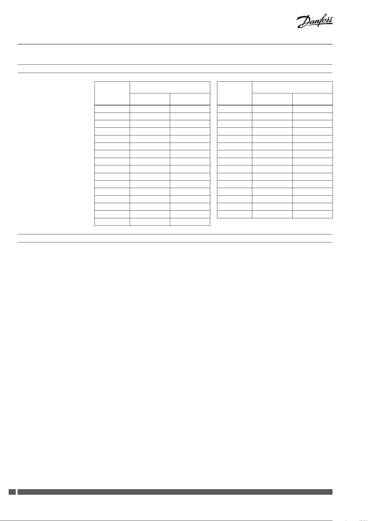
2. Technical data
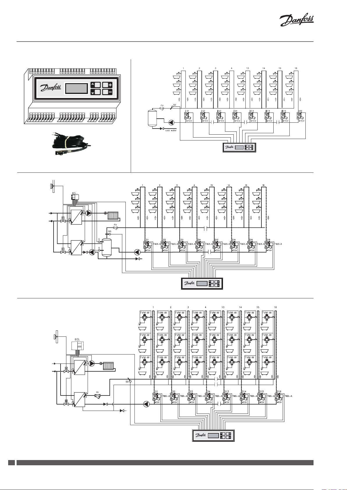
The CCR2 is a control used for optimising the
thermal disinfection process in hot water
systems with functions such as temperature
registration and monitoring circulation hot water
actuators type TWA - A and remote temperature
sensors PT1000, type ESMB, installed on each
thermostatic circulation valve, type MTCV
(Multifunctional Thermostatic Circulation Valve).
systems. The control is connected to thermo
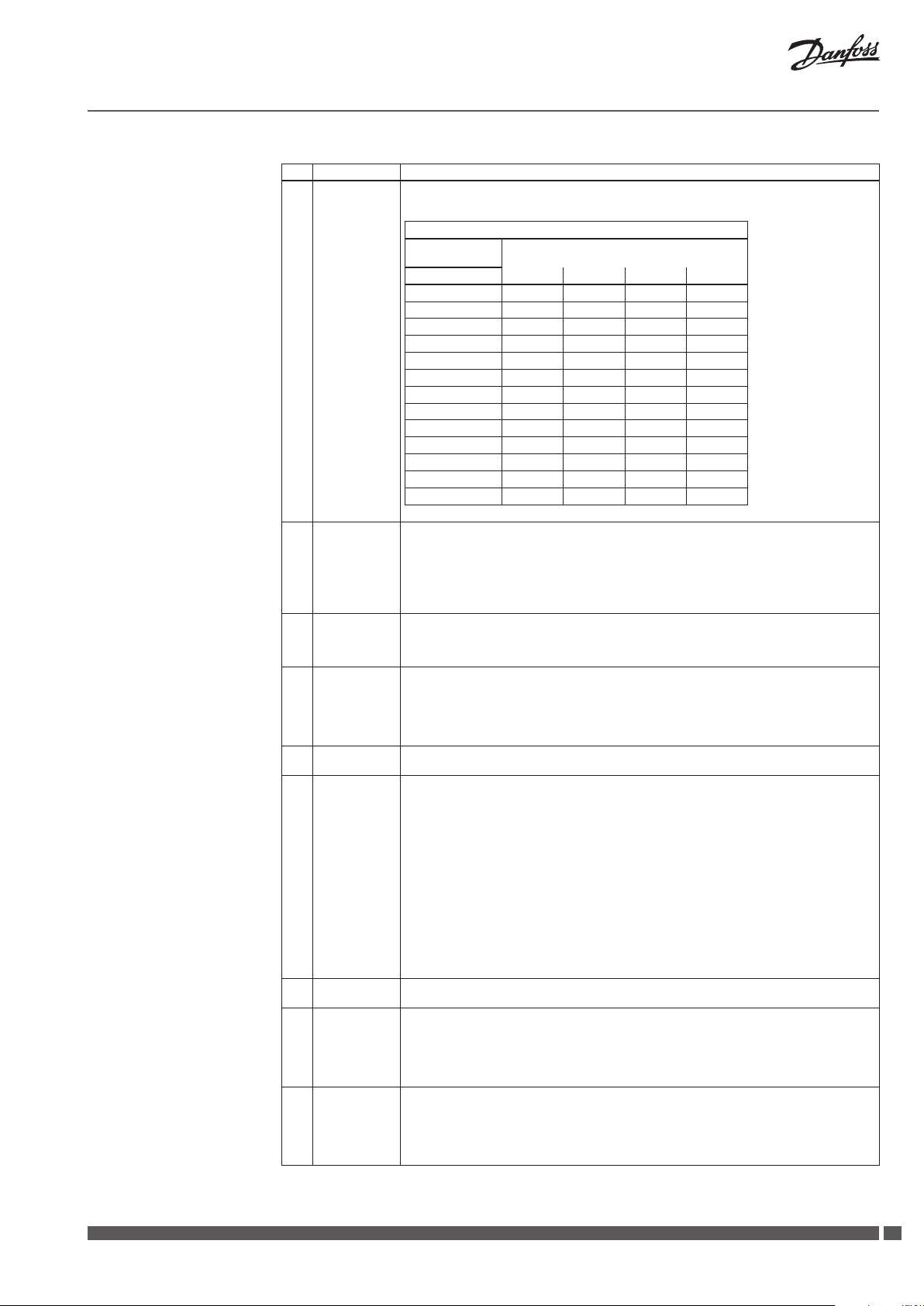
Temperature sensor (S0, S1 … S16) Pt1000, S0- type ESMC / ESM11, S1 … S16 – type ESMB
Temperature range (registration) –20 °C … +120 °C
Measuring accuracy ± 0,1 K
Inputs: B1 and B2 Free contact (5 V 1 mA)
Number of control valves (risers) 16
Output signal to actuators (Triac type) 24 VAC max. 1 A
Alarm signal output (Triac type) 24 VAC max. 1 A
Relay output 0 … 24 VAC/DC max. 1 A
OC output ( Transistor typ e) 0 … 20 V DC NPN Open collector max. 200 mA
Type of memor y card (included) SD (512 MB factory card, build in CCR2)
Maximum memory card 2 GB
Timer: Real time clock Built-in bat tery - service life 10 years
Ambient temperature 0 … 50 °C
Transport temperature –10 … +60 °C
IP rating IP 20,
Power supply 24 VAC
Power consumption 6 VA
Weight 0,9 kg
Installation DIN rail 35 mm
3. Installation
4. Switching the control on
For easy access, the CCR2 control is installed in
the technical box on DIN rail 35 mm. Box with
DIN rail should be mounted onto the wall (sub station or boiler room) as close as possible to the
heat source. DIN rail and box are not included. It
Before switching the control on for the rst
time, disconnect all cables and connect a 24 VAC
source to the disconnected power plug. Use a
voltmeter to measure the voltage on the power
cable plug before it is connected to the control.
If the voltage is correct:
1. Read the instructions before you operate the
control
2. Disconnect all cables
3. Connect the power to the transformer (not
connected to CCR2)
4. Turn on the power to the transformer
5. Veried currency - 24 V
6. Connect the cable from the transformer to the
CCR2 input
is recommended to install the standard 24 VAC
transformer in the same box as CCR2 (not supply).
Do not install (and remove) SD card when the
CCR2 is connected to the current. It must be
switched o (risk of losing data).
The control should display its name and the
software version – CONTROLLER START MENU –
display according to point 5.
Before any plugs are connected to the control’s,
input and output connectors:
1. Set all parameters on the control
2. Make sure that there is no external voltage on
the temperature sensor plugs
3. Make sure that the voltage on the relay
contacts is not too high (max. 24 VAC)
Heating Solutions VI.D1.E2.1R SMT/SI
55
Page 6

Installation Guide CCR2
5. Control start menu
Start process
After having switched the control detected
SD card on and veried the card memory, the
following will happen.
If the card is correctly placed, the control will
verify the present les:
• access
• oneset
• allset
If the above - mentioned les are detected, the
control will ask whether they should be used or
aborted.
If no les (new card, used for the rst time) there
will be no request.
The next control will automatically generate a
folder with the following les:
• folderACCESS:
allow change of access code to menu (details
on request or www.danfoss.com)
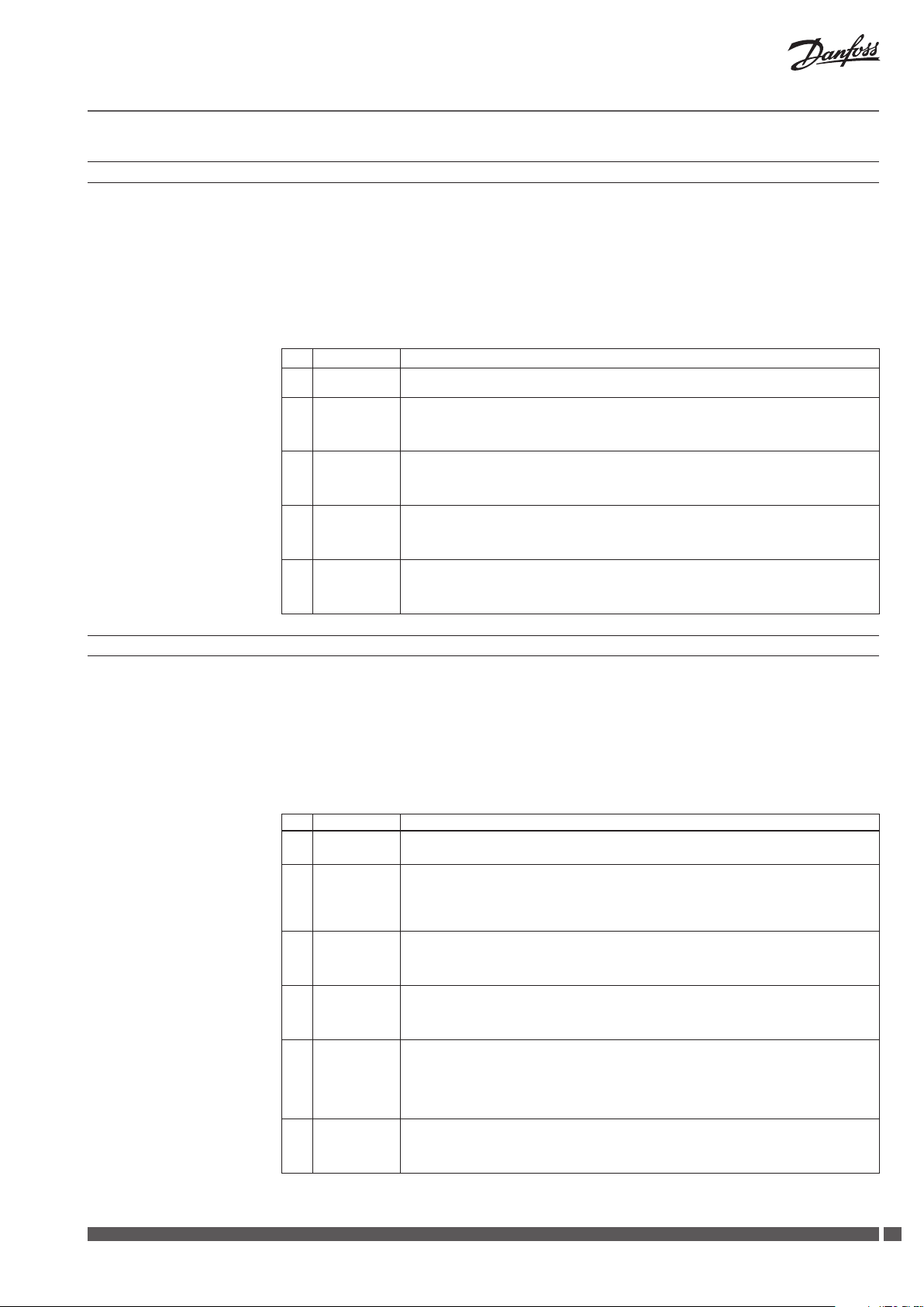
No. LCD Display READING DESCRIPTION
1 Danfoss
CCR - 2.60
2 SD Free
… ..
3 SD Free
512 MB
4 NO
SD CARD!
5 AccesCod
Read?
6 AccesCod
DONE!
7 AccesCod
Aborted!
8 OneSet
Read?
9 OneSet
DONE!
10 OneSet
Aborted!
11 AllSet
Read?
12 AllSet
DONE!
13 AllSet
Aborted!
14 72254
123456
15 Thu On
12: 59: 32
16 10/9/06
12: 59: 32
Welcome Menu
Diagnosis: available SD card memor y
Available memory In MB
No SD card in CCR2
Only when no card in CCR2.
Do you want to change code access to the control?
Press simultaneously „+” and „▼” to change code access to settings.
Information appears only if SD card includes changed le code: ACCESS and changes were conrmed
Changes were done!
Information appears only if SD card includes changed le code: ACCESS and changes were conrmed
Reset was not done.
Information appears only if SD card includes changed le code: ACCESS and changes were ignored.
Do you want to change all settings and create new settings on PC? Press simultaneously „+” and „▼”
to make changes.
Inquiry appears only if on the SD card the CCR2 nds new settings predened on PC le: SETTING.
Note: recommended only for service sta.
Changes were done!
Information appears only if the SD card includes a le with predened SE TTINGS: and changes were
conrmed.
A new setting was abor ted!
Information appears only if SD card includes changed le: SE TTING and changes were ignore.
Do you want to use data from le: allset from SD card and change all settings in the CCR2?
Press simultaneously „+” and „▼” to change all settings.
Inquiry appears always from second run of the control with SD card.
AllSet – can be used to remove settings from CCR2 to another CCR2.
Changes were done!
Information appears only when SD card includes AllSet le and changes were conrmed.
Changes of Allset were aborted
Information appears only when SD card includes AllSet le and changes were ignored.
Series number of CCR2 and number of sof tware.
Code used for services.
Day of the week : Mon, Tue, Wed, Thu, Fri, Sat, Sun.
Status of working schedule:
“On”: disinfection permitted in set schedule ;
“O”: disinfection not permitted in set schedule
12: 59: 32 Real time: hour, minute, second
Real date
Real time: hour, minute, second
• folderDATA:lewithrecorddate
• folderSETTINGSwithles
- allset: le with settings. Each time the of
control is switched on, setting parameters
are archived. This function provides
verication history of all settings
- arch.set: le with archive of all settings.
When switching the control on for the 2nd
time with the above - mentioned record le,
the request procedure for setting change or
abortion will start.
Display information during the start process
After switching the CCR2 control on, the LCD
display automatically presents the start menu.
The table below shows the various information
and change possibilities during the operation of
the CCR2.
6
SMT/SI VI.D1.E2.1R Heating Solutions
Page 7

Installation Guide CCR2
6. Control reading menu
When the setup is complete, the reading display
will be shown on the screen.
09 - 10 - 06
12: 59: 32
No. LCD Display READING DESCRIPTION
17 10/9/06
12: 59: 32
18 AC: 0117
… … … …
19 DayToEnd
148
20 In B1 - M
… … .
21 In B2 - M
… … …
22 Out T1 0V
… … …
23 Alert T2
… … ..
24 Rel C - NO
… … .
25 Disinfec
… … … … ..
26 Disin.Is
… … … ..
27 Dis.SetT
… °C
28 Adv.Fact
… .%
29 GroupNr
… … ..
The current time and date.
Information display alternately with information about current date e.g.: Sat - schedule status and
time. Display presented above. Data used in archive le.
“AC: 0117” - How much data is stored in SD card:
Recorded data is indicated by counter, e.g.0117 – 117 records were done. When number exceeds
9999, the counter starts counting from 0000.
Alternately with Archiver InProces – data is recorded
Alternately with Archiver Disable – data is not recorded
Alternately with NoSD card – no SD card in CCR2
How much data can be stored per day in the memory card (for actually settings)
Input status B1 - M
Open – input B1 open
Close – input B1 close to M
Close ( shor tcut B1 - M) can be used for disinfection initiation ( look to “DisSourc” in Install Menu.)
Function is used in parallel and sequences connection.
Input status B2 - M
Open – input B2 open
Close – input B2 close to M
Close (shor tcut B2 - M) always nished disinfection process. The end of the disinfection process can
be realised automatically (look to: Install Menu – This is Master) or manually if it is necessary to stop
the process. When it is done manually, LCD displays information – disinfection fault.
Output status T1 - 0V (open collector)
Open – T1 open
Close – T1 close.
T1 signal is used for permitting signal to next CCR2 in parallel or sequences connection (look to “CCR
Sys” in Install Menu)
Output status Alert T2 (triack output)
Active – signal 24 VAC on the T2 output
NotActive – signal 0 V on the T2 output
T2 is used for alarm signal in the below situations:
- sensor failure: e.g. shortcut in sensor circuit (SensFaul)
- when disinfection process was not done successfully in riser (FaultDis)
- disinfection was stopped manually by B2 shortcut
Signal alarm can be cancelled in enter of any menu and af ter removal of the reason for the alarm (e.g.:
after sensor repair)
Output status C - NO ( Free Contact Relay status: C - NO - NC)
Open - output C - NO open ( it means C - NC is closed)
Close – output C - NO closed ( it means C - NC is opened)
Free Contact Relay is closed, when CCR2 requests high temperature from ECL or another heat source
control for disinfection process continuation. This output can be used also for external signal to
indicate disinfection process. Supporting relay is needed.
Is disinfec tion permitted?
Choice bet ween:
Enable – disinfection is permitted
Disabl e – disinfection is switched o in settings: BASIC MENU point: “Disinfec Disable” No. 30,
chapter 8.
Is disinfec tion currently in progress?
Choice bet ween:
In Proces – disinfection is in progress;
Finished – disinfection is completed.
The set disinfection temperature.
The choice range is provided in a table below.
Calculated disinfection progress ratio, updated after each division period.
Number of risers in the currently disinfected group.
If no division was made, this is the total number of risers. Option of choice divides risers into groups
during disinfection or is used in INSTALL MENU, number 39, chapter 9. Function: To be used division
enables disinfection process to accelerate in extensive hot water circulation installations.
Sat On
12: 59: 32
Pressing the “+” key, turns the subsequent
reading display on. The “ - ” key turns the previous
reading display on. When pressing an arrow “▲”
the reading displays is quitted and the ACCESS
CODE menu comes up, described in chapter 7.
When exitting from the menu, the rst reading
display is shown. A list of readings and possible
displayed options are shown in the table below.
Heating Solutions VI.D1.E2.1R SMT/SI
77
Page 8

Installation Guide CCR2
No. LCD Display READING DESCRIPTION
30 Sensor 0
… °C
31 Valve 1
… … %
32 R1 … h Riser R1 – riser status information:
7. Menu Access Code - access to settings
Sensor S0 temperature. The same readings apply to sensors S1 … S16.
In right side after the temperature info can appear sign: L (Low) or H (High)
These signs indicate that real temperature in the system exceed Required Temperature
Required range set in points: 52-55 in the Install Menu. Function used for temperature alarm output.
When is no: L or H – real temperature in the Required set ting range.
Press “+” to move between sensors. Or it can appear:
Open - no sensor or break sensor circuit
Closed – shortcut to ground in sensor circuit
Status of valve: V1 … V16.
Press “+” to move between valves. Or one of the following:
On – open, valve V1 is currently powered up, (taking PWM into account).
O – closed, valve V1 is currently powered down (taking PWM into account).
… ..% – valve open ratio – percentage of lling the PWM function (0 … 100 % in 10 % steps).
R1 … h.. – overheating time remaining to complete the disinfection process for the given riser
(countdown timer).When the process is nished, the timer will reset to start time.
Disin – disinfection is currently in progress for riser R1,
HoldDi s – disinfection is currently interrupted for riser R1 following group division,
EndDis in – disinfection was completed successfully in riser R1
FaulDis – disinfection has failed in riser R1
SensFaul – temperature senor fault in this riser
To set the parameters, press the up arrow key
“▲” from
Reading Menu and enter the access code
(three digits) to enter the required settings group.
The “+/ - “ keys change the digit values in the
code, the arrow keys “▲/▼” navigate the cursor
through the code digits. To enter the required
setting group, press arrow key “▲” after last
No LCD Display ACCESS CODE - FUNCTION DESCRIPTION
33 AcceCode
***
Access codes to the control’s set ting menus. Available menus:
– Basic menu ( code: 359), basic setting menu
– Install menu (code: 427). Advanced settings
– Schedule menu (code 760). Weekly schedule programme settings for disinfection process
– Real Time menu (code 576). Real time clock and date setting
– Quadruple pressing up arrow key “▲” without entering any code will give access to “SD Card
Exchange”. SD card can be safely pulled out from CCR2 (process of date recording is interrupted).
The access codes are standard for the individual
menus.
It is possible to change the access codes by
entering new codes through the SD memory card
and restarting the control. Detailed instructions
are available on request.
The settings of the control can be entered using
the keypad or globally through the SD memory
card (control restart required). Details are
available on request.
code digit. If the code is not correct, the display
shows: SD Card Exchange – meaning that the
SD card can safely be pulled out from CCR2
(process of date recording is interrupted). The
settings menu is closed automatically after four
minutes of inactivity, and the display returns to
Reading Menu.
The manufacturer reserves the right to change
the control’s settings and readings in production
to improve handling and functionality. An up to - date list of settings for the given software
version is available on the Danfoss website.
New settings can automatically upgrade CCR2
through the SD memory card (control restart
required).
8
SMT/SI VI.D1.E2.1R Heating Solutions
Page 9

Installation Guide CCR2
8. Basic menu settings (CODE 359)
From ACCESS CODE menu enter code: 359
(procedure in chapter 7). The Basic menu is
displayed in details in the table below. The arrow
keys “▲/▼” move the menu windows, the “+/ -
“keys change the values in the window selected
by the arrows. To exit the setting menu, press the
up arrow key “▲” after changing the last setting.
No LCD Display BASIC MENU - FUNCTION DESCRIP TION
34 Basic
Menu
35 Disinfec
…
36 Dis.Temp
… °C
37 DisinTime
… h … min
38 Ecs?
+ YES
ESC?
+ YES
Information about menu: Basic
Is disinfec tion permitted?
Possible choices:
- Enable – disinfection permitted
- Disabl e – disinfection is switched o
Set disinfection temperature.
Disinfec tion is initiated when the temperature on sensor S0 exceeds the set temperature. Exceeding
the set temperature on a riser sensor (S1 … S16), triggers the disinfection time countdown for the
given riser.
Set disinfection time in the risers.
Disinfec tion time countdown is independent for each riser. Minimum required and maximum
recommended time depend on the disinfection temperature and should be selected from the table
in chapter 13.
Exit windows from Basic Menu. Enter “+” to close the setting or the basic menu will close automatically
after 4 minutes.
9. Install menu settings (Code: 427)*: recommended only for service
The setting menu is closed automatically after 4
minutes of inactivity.
Note:
When entering the Basic Menu, the disinfection
process and alarm signal are discontinued..
From ACCESS CODE menu enter code: 427
(procedure in chapter 7). The Install Menu is
displayed in details in the table below. The arrow
keys “▲/▼” move the menu windows, the “+/ - “
keys change the values in the window selected
by the arrows. To exit the setting menu, press the
up arrow key ”▲” after changing the last setting.
No LCD D isplay INSTALL MENU - FUNCTION DESCRIPTION
39 INSTALL
Menu
40 Disinfec
…
41 Dis.Temp
… °C
42 DisinTime
… h … min
43 Cir.Temp
… °C
44 Divide
…
Information about menu: Install
Recommended for service.
Is disinfec tion permitted
Possible choices:
- Enable - disinfection permitted
- Disabl e - disinfection is switched o
Factor y setting: En able
Set disinfection temperature. The disinfection is initiated when the temperature of sensor S0 exceeds
the set temperature. Exceeding the set temperature on a riser sensor (S1 … S16), triggers disinfection
time countdown for the given riser.
Factor y setting: 65 ° C
Set disinfection time in the risers.
Disinfec tion time countdown is independent for each riser. Minimum required and maximum
recommended time depends on the disinfection temperature and should be selected from table in
chapter 13.
Factor y setting: 15 min
Electronically controlled circulation temperature after disinfection in riser. The CCR 2 can maintain
the requested circulation temperature in the riser after the disinfection process. This function is
recommended for control valves with only actuators (PI control signal). For self - acting valves like
MTCV (with basic thermostat element ) recommended setting is 5 °C.
Factor y setting: 5 °C
Dividing risers into groups:
- Enable – when the disinfection progress is slower than the set progress in
MinAdvan in p osition 42,
- Disable – switched o regardless of the disinfection progress.
Factor y setting: En able
The setting menu is closed automatically after 4
minutes of inactivity.
Entering the Menu Settings, discontinue
disinfection process and alarm signal.
Heating Solutions VI.D1.E2.1R SMT/SI
99
Page 10

Installation Guide CCR2
No LCD D isplay INSTALL MENU - FUNCTION DESCRIPTION
45 Div.Time
… min
46 MinAdvan
… %
47 Riser Nr
48 This is
… ..
49 CCR Sys
… … .
50 Int.Time Integration time of the disinfection temperature (and circulation temperature) sustenance process in
51 Prop.Fac Control gain of the disinfection temperature (and circulation temperature) sustenance process
52 Req.Temp
… °C
53 Dif. Temp
in + …. °C
54 Dif. Temp
in - … °C
55 Alarm DLY
… min
…
Group division period. CCR 2 will calculate the average disinfec tion progress periodically every
number of minute set here from the moment that the disinfection starts. It will then decide whether
to divide the risers into groups or not.
Factor y setting: 20 m in
Minimum average disinfection progress in percentage calculated between the group division times,
above which the risers will not be divided into groups. If disinfection progress will be lower then e.g.
20%, the risers will be divided into groups.
Factor y setting: 25 %
Number of risers connected to the CCR2.
Factor y setting: 16
Function used: when CCR2 is connec ted to ECL (another control) or to another CCR2.
Determines whether the CCR2 works as Master or Slave – only valid in parallel or sequence connection
with another CCR2 and connection to e.g.: ECL.
Example: one Master and t wo Slaves
If disinfec tion is not activated, the relay (C/NC/N0) will make shor tcut C and NC. When disinfection is
activated, the relay (C/NC/N0) will change shortcut to C and N0 –
This short - cut C/NC allows the CCR2 to keep a continuously high supply temperature by ECL control
or another control. Available settings:
Master – keep shortcut (C/NC) until conrmation about nished disinfection. Process will come from
last CCR2 (Slave) through shortcut B2 to M (fault to frame).
Slave – keep shortcut (C/NC) only in this CCR2 (Slave) until nished disinfec tion in this part of the
installation controlled by this CCR2.
Factor y setting: Sl ave ( always for sin gle CCR2 )
Function used: when CCR2 is connected with another CCR2. Big extended systems.
Parallel – disinfection i s performed at the same ti me. If disinfection signal appears, output T1 becomes
shortcut with M. This is the signal for CCR2 to start the disinfection. Parallel function allows the star t of
the disinfection in all CCR2 at the same time, as Master CCR2 revokes the disinfection order for CCR2 Slave 1, and Slave1 in turns relays the revocation to CCR2 - Slave 2. (scheme - g 10 and 11)
Sequen ce – disinfection step by step ( rs t CCR 2 , second CCR2 etc)
If disinfec tion signal appears, the disinfection process star ts only in rst CCR2 (Master) and after
implementation (successful per formed or not), output T1 becomes shortcut with M, which allows the
start of the process in another CCR2. When the CCR2 will perform the last disinfection, the rst CCR2
(Master) will send a signal to ECL (or another control) and the supply disinfection temperature returns
to comfort temperature. (scheme on g. 8 and 9)
Factor y setting: Par allel
risers controlled by MTCV valves. The shorter the time, the quicker temperature changes (no stabile
regulation). The longer the time, the slower reaction for temperature changes (stable regulation).
Factor y setting: 60 s ec
in risers controlled by MTC V valves. The higher the gained control, the bigger valves reaction (no
stabile regulation). The lower the gained control, the weaker reaction for temperature change (stable
regulation).
Factor y setting: 100
Set Required Temperature in installation.
Setting range bew teen +10 °C and +100 °C.
This setting is used for temperature alarm output when real temperature in system exceed upper and
lower deviation count from Required Temperature.
Factor y setting : 55 °C
Set upper deviation temperature counted from Required Temperature. Temperature alarm output
indicated signal when temperature exceed this range.
Setting range bew teen +1 °C and +20 °C
Factor y setting: +10 °C
Set lower deviation temperature counted from Required Temperature. Temperature alarm output
indicated signal when temperature drop below this range.
Setting range bet ween −1 °C and −20 °C
Factor y setting: -10 °C
Set ALARM DeLaY. The temperature alarm delay when real temperature exceed exceed upper and
lower deviation counted from Required Temperature.
Setting range bet ween 0 minute and 100 minute
Factor y setting : 10 min
10
SMT/SI VI.D1.E2.1R Heating Solutions
Page 11
Installation Guide CCR2
No LCD D isplay INSTALL MENU - FUNCTION DESCRIPTION
56 Cor
S0 …
… °C
57 Rel.Test
… … … .
58 AlertRel
… …
59 Archiver
60 ArchFreq
61 DisSourc
… … ..
62 BMSAdres CCR2 address in BMS system
63 BMS T YPE Type of date transmission:
64 DateForm Form of date display:
…
…
Sensor calibration: S0 … S16 in range: ±9,9 °C
Do not make calibration when sensor cables are shorter than 10 meters.
For longer cable then 10 meters, used correction factors from table below.
Correction factor
total length
(two - core cable)
in meter 0,5 mm
10 - 0,2 - 0,1 - 0,1 - 0,1
15 - 0,5 - 0,3 - 0,2 - 0,1
20 - 0,4 - 0,3 - 0,2 - 0,1
25 - 0,5 - 0,3 - 0,3 - 0,1
30 - 0,6 - 0,4 - 0,3 - 0,2
35 - 0,7 - 0,5 - 0,4 - 0,2
40 - 0,8 - 0,5 - 0,4 - 0,2
45 - 0,9 - 0,6 - 0,5 - 0,2
50 - 1,0 - 0,7 - 0,5 - 0,3
75 - 1,5 - 1,0 - 0,8 - 0,4
100 - 2,0 - 1,4 - 1,0 - 0,5
125 - 2,5 - 1,7 - 1,3 - 0,6
150 - 3,0 - 2,0 - 1,5 - 0,8
Factor y setting: 0 °C
Relay test ( Triac output)
AUTO – all work automatically
V1 … V16 – forced signal for valves output V1 … V16
Rel C - NO - forced signal for relay C/NO
T1 Out - forced signal for output T1 (open collector)
T2 Out – forced signal (24 VAC) for alarm T2 .
Factor y setting: Au to
Alarm output (Triac)
StillOn – continuous alarm signal: T2 – 24 VAC
Pulse – pulse alarm signal 24 VAC every second
Factor y setting: Pu lse
Information about data archiving:
Never – the feature is switched o,
1 File – data is stored in one le on the SD card,
2 Files – data is stored alternatively in two les to improve write reliability. This function decreases
term of data storage (twice).
Factor y setting: 1 Fil e
Data archiving interval. The time can be set to any value between 10 seconds and 4 hours.
Factor y setting: 1 mi n
Disinfec tion sources for running disinfection and continuing the process, There are a few
combinations which allow initiation of the process based on one signal or in relation to many needed
signals. Disinfection is initiated when:
S0 – sensor S0 reports a temperature higher than the disinfection temperature
B1 – B1 input shorted to ground,
S0+SCH – sensor S0 repor ts a temperature higher than the disinfection temperature in the scheduled
time period,
B1+SCH – B1 input shorted to M (ground) in the scheduled time period,
SCH - weekly schedule runs and continues until it is complete, even if schedule was to terminate it,
S/B0+SCH – B1 input shorted to M (fault to frame, ground) or sensor S0 reports a temperature higher
than the disinfection temperature in the scheduled time period,
S0&B0 – B1 input shorted to M and sensor S0 reports a temperature higher than the disinfection
temperature,
S0&B0+SCH - B1 input shorted to M and sensor S0 repor ts a temperature higher than the disinfection
temperature in the scheduled time period.
Factor y setting: S0
Factor y setting: 1
ModBus 96 (9.600)
Mod Bus 19 (19.000)
ModBus 38 (38.400)
FBus
Factory setting: ModBu s 96
YY - MM - DD – year, month, day
YY - DD - MM – year, day, month
DD - MM - YY – day, month , year
MM - DD - YY – month, day, year
Factor y setting: Y Y - MM - DD
cable cross section
2
0,75 mm2 1,00 mm2 1,5 mm
2
Heating Solutions VI.D1.E2.1R SMT/SI
1111
Page 12

Installation Guide CCR2
No LCD D isplay INSTALL MENU - FUNCTION DESCRIPTION
65 CCR2 is
… … .
66 Reset
… … .
67 Ecs?
+ YES
10. SCH setting: weekly schedule programme menu settings (code 760)
Status of CCR2:
Register - functions only as temperature registration
Reg+Dis - functions as disinfection control with temperature registration
Factor y setting: Re g+Dis
Reset to factory settings
Yes - return to factory settings
No – keep adjusted settings
Note: To complete res et procedure turn CCR3 o and back on .
Exit windows from Install Menu. Enter “+” to close setting or basic menu will close automatically after
4 minutes
From ACCESS CODE menu enter code: 760
(procedure in chapter 7). The Schedule menu is
displayed as in the table below.
The arrow keys “▲/▼” move the menu windows,
the “+/ - “ keys change the values in the window
selected by the arrows.
No LCD D isplay PRG - SCHED ULE PROGRAMME M ENU - FUNCTION DESCRIP TION
68 Schedule
Menu
69 P1 Start
10: 20
70 P1 Start
10: 20
71 P1 Stop
10: 20
72 P1 Stop
10: 20
73 P1 Activ
A12 - - - 67
74 Ecs?
+ YES
Information about menu: Schedule
Programme P1 starts time “hour” for the week ly schedule. The same settings apply for programmes
P2 … P7.
Programme P1 starts time “minute” for the weekly schedule. The same settings apply for programmes
P2 … P7.
Programme P1 stops time “hour” for the weekly schedule. The same settings apply for programmes
P2 … P7.
Programme P1 stops time “minute” for the weekly schedule. The same settings apply for programmes
P2 … P7.
Sets the ac tivity of the entire P1 programme and its activities for individual days of the week .
The arrow keys”▼/▲” navigate the cursor through the digits. The “+/ - “ keys change the digit values.
Figures 1 … 7 represent days of the week:
1 – Monday, 2 – Tuesday … 7 – Sunday.
The rst setting to the left can be A or N:
A – Programme P1 is active - subsequent set tings are read,
N – Programme P1 is entirely deactivated - subsequent settings 1 … 7 are dismissed, and the
programme is not star ted.
The second left setting:
1 – Programme P1 is activated on Monday.
“ - “ – Programme P1 is not activated on Monday.
The third left setting:
2 – Programme P1 is activated on Tuesday.
“ - ” – Programme P1 is not activated on Tuesday.
The four th left setting:
3 – Programme P1 is activated on Wednesday.
“ - “ – Programme P1 is not activated on Wednesday.
The fth left setting:
4 – Programme P1 is activated on Thursday.
“ - “ – Programme P1 is not activated on Thursday.
The sixth left setting:
5 – Programme P1 is activated on Friday.
“ - “ – Programme P1 is not activated on Friday.
The seventh left setting:
6 – Programme P1 is activated on Saturday.
“ - “ – Programme P1 is not activated on Saturday.
The eighth left set ting:
7 – Programme P1 is activated on Sunday.
“ - “ – Programme P1 is not activated on Sunday.
The same Ac tivity settings apply for programmes P2..P7.
Exit windows from Install Menu. Enter “+” to close setting or basic menu will close automatically after
4 minutes
To exit the setting menu, press the up arrow
key after changing the last setting. The settings
menu is closed automatically after 4 minutes of
inactivity.
Entrance to the Menu Settings discontinue
disinfection process and alarm signal.
12
SMT/SI VI.D1.E2.1R Heating Solutions
Page 13

Installation Guide CCR2
11. Real time clock setting (code 576)
From ACCESS CODE menu enter code: 576
(procedure in chapter 7). The Real Time menu is
displayed as detailed in the table below.
The arrow keys “▲/▼”move the menu windows,
the “+/ - “keys change the values in the window
selected by the arrows. To exit the setting menu,
press the up arrow key after changing the last
setting. The setting menu is closed automatically
after 4 minutes of inactivity.
Entering the Menu Settings, discontinue
disinfection process and alarm signal.
No LCD D isplay REAL TIM E CLOCK - FUNCTION DESCRIP TION
75 Real Time
Menu
76 RealTime
12: 00: 00
77 RealTime
12: 00: 00
78 RealTime
12: 00: 00
79 Year Sets the year for the current date
80 Month Sets the month for the current date
81 Day Sets the day for the current date
82 Ecs?
+ YES
Information about menu: real Time
Sets the real time clock “hour”
Sets the real time clock “minute”
Sets the real time clock “second”
Exit windows from Install Menu. Enter “+” to close setting or basic menu will close automatically after
4 minutes
12. Using the data storage card
The SD card may never be installed in/or removed
from the CCR 2 when data is being written to it.
Disrespecting this rule may lead to:
– data loss
– SD card damage
– CCR 2 control damage.
INSTALLING THE SD CARD
Disconnect the control from the power supply
for at least ve seconds before inserting the SD
card. The SD card may only be installed after this
pause.
REMOVING THE SD CARD
From ACCESS CODE menu quadruple press up
arrow key “▲” without entering any code it will
give access to “SD Card Exchange”. SD card can
be pulled out safely from CCR2 (process of date
recording is interrupted).
Power failures occuring when data is written to
the SD card may also corrupt the archive or even
damage les stored on the card. To reduce the
risk, it is recommended to use a buered power
supply for a CCR 2 used with the data archiving
function and to set the “Archive” setting to “2
Files.” The archived les will be doubled, but the
storage space is halved.
Heating Solutions VI.D1.E2.1R SMT/SI
1313
Page 14
Installation Guide CCR2
13. Temperature set in the circulation risers and disinfection time:
Temperature
of disinfection
[ °C]
50 6 h 20 minute 7 h 30minute
51 6 h 10 minute 7 h 20 minute
52 4 h 00 minute 5 h 50 minute
53 2 h 00 minute 4 h 00 minute
54 1 h 00 minute 2 h 00 minute
55 0 h 50 minute 2 h 00 minute
56 0 h 40 minute 1 h 20 minute
57 0 h 20 minute 1 h 00 minute
58 0 h 15 minute 0 h 50 minute
59 0 h 15 minute 0 h 45 minute
60 0 h 14 minute 0 h 40 minute
61 0 h 13 minute 0 h 35 minute
62 0 h 12 minute 0 h 30 minute
63 0 h 12 minute 0 h 28 minute
64 0 h 11 minute 0 h 27 minute
65 0 h 11 minute 0 h 26 minute
Time set ting for therma l disinfectio n
in: hour … Minute …
Minimum
requir ed
Maximum
recommended
CCR2 ModBus protocol details
Data type : Coil [bool] Coil No. Description
MB_CoilOut [0] - disinfection permitted
MB_CoilOut [1] - disinfection in progress
MB_CoilOut [2 … 9] - open valves ( 0 … 7)
MB_CoilOut [10 … 17] - risers with open valves (riser: 8 … 15)
MB_CoilOut [18 … 25] - riser with disinfection error (riser: 0 … 7)
MB_CoilOut [26 … 33] - riser with disinfection error (riser 8 … 15)
MB_CoilOut [34 … 41] - riser with nished disinfection, success (riser: 0 … 7)
MB_CoilOut [42 … 49] - riser with nished disinfection, success (riser: 8 … 15)
MB_CoilOut [50 … 57] - riser in disinfection group (riser: 0 … 7)
MB_CoilOut [58 … 65] - riser in disinfection group (riser: 8 … 15)
MB_CoilOut [66] - alarm
MB_CoilOut [67] - disinfection in progress when TS0 is achieved
MB_CoilOut [68] - permission to run next CCR
MB_CoilOut [69] - status of binary input : B1
MB_CoilOut [70] - status of binary input : B2
Temperature
of disinfection
[ °C]
66 0 h 10 minute 0 h 25 minute
67 0 h 9 minute 0 h 25 minute
68 0 h 8 minute 0 h 22 minute
69 0 h 7 minute 0 h 21 minute
70 0 h 6 minute 0 h 20 minute
71 0 h 6 minute 0 h 18 minute
72 0 h 6 minute 0 h 14 minute
73 0 h 5 minute 0 h 12 minute
74 0 h 4 minute 0 h 10 minute
75 0 h 3 minute 0 h 10 minute
76 0 h 3 minute 0 h 10 minute
77 0 h 2 minute 0 h 9 minute
78 0 h 2 minute 0 h 8 minute
79 0 h 2 minute 0 h 6 minute
80 0 h 2 minute 0 h 6 minute
Time set ting for therma l disinfectio n
in: hour … Minute …
Minimum
requir ed
Maximum
recommended
Data type Register [integer] Register No. Description
MB_RegisterOut [0 … 8] - temperature sensors S0 … S8 (8000 <=> 80 °C)
MB_RegisterOut [9 … 16] - temperature sensors S9 … S16 (8000 <=> 80 °C)
MB_RegisterOut [17 … 24] - time needed to nished disinfection for risers 1 … 8 [in minutes ]
MB_RegisterOut [25 … 32] - time needed to nished disinfection for risers 9 … 16 [in minutes]
MB_RegisterOut [33] - selected disinfection time
MB_RegisterOut [34] - degree of disinfection progress when system is divide for group
MB_RegisterOut [35] - number of risers in group
MB_RegisterOut [36+0 … 7] - control signal (opening) in % for valve in risers : 1 … 8
MB_RegisterOut [44+0 … 7] - control signal (opening) % for valve in riser: 9 … 16
Baud rate: data bits stop bits parity
9.600 8+1 N
19.200 8+1 N
38.400 8+1 N
14
SMT/SI VI.D1.E2.1R Heating Solutions
Page 15

Zasilanie
AC
24V
B
RS 485
ModBus
do BMS
CCR
Installation Guide CCR2
RS 485
CC
R
CCR
ZAWORY STREF V1.. V8
WYJŒCIA TRIAKOWE
C
V2 V3 V4 V5 V6 V7 V8
V1
ZAWORY STREF V1.. V8
WYJŒCIA TRIAKOWE
TEMPERATURY
STREF S1.. S8
M S1 S2 S3 S4 S5 S6 S7 S8
TEMPERATURY
STREF S1.. S8
start
TEMP.
dezyn.
dezyn.
S0
M B1 M B2 M M A
S0
CCR
stop
Fbus
C
V1 V2 V3 V4 V5 V6 V7 V8
158.5 mm
M S1 S2 S3 S4 S5 S6 S7 S8 M B1 M B2 M M AS0 B
CCR2
CONTROLLER
ZAWORY STREF V9.. V16
WYJŒCIA TRIAKOWE
V13
V10 V9
C
ZAWORY STREF V9.. V16
WYJŒCIA TRIAKOWE
V11 V12
V15 V16
V14
Rys. 4 Schemat po łączeń elektrycznych
Rys. 5 Wymiary i montaż
TEMPERATURY
STREF S9.. S16
M S9 S10 S11 S12 S13 S14 S15 S16
TEMPERATURY
STREF S9.. S16
CCR2 - CONTROLLER
SD
FLASH
CARD
NO T1
0V 0V
NC
ALARM
Start
dezynfekcji
T2
24V
C
Do ECL
Wymuszenie
przegrzania
158.5mm
Karta SD nie może być instalowana
i wyjmowana pod napieciem.
W celu instalacji i wyjęcia karty
wyłacz zasilanie do CCR2!
CCR2 - CONTROLLER
90 mm
V13
V10V9
V15 V16
V11 V12
90 mm
V14
90 mm
35 mm
58 mm
C M S9 S10 S11 S12 S13 S14 S15 S16
31 mm
NO T1T20V 0V 24V
C
NC
10
35 mm
62 mm
start
stop
ZAWORY STREF V1.. V8
WYJŒCIA TRIAKOWE
C
V2 V3 V4 V5 V6 V7 V8
V1
ZAWORY STREF V1.. V8
WYJŒCIA TRIAKOWE
TEMPERATURY
STREF S1.. S8
M S1 S2 S3 S4 S5 S6 S7 S8
TEMPERATURY
STREF S1.. S8
TEMP.
dezyn.
S0
M B1 M B2 M M A
S0 B
dezyn.
Fbus
ModBus
do BMS
CCR2
CONTROLLER
Rys. 6 CCR2 połączenie do ECL
Heating Solutions VI.D1.E2.1R SMT/SI
ZAWORY STREF V9.. V16
WYJŒCIA TRIAKOWE
V13
V10 V9
C
ZAWORY STREF V9.. V16
WYJŒCIA TRIAKOWE
Połączenie CCR2 do ECL lub
innego sterownika w źródle ciepła
( kocioł, węzeł cieplny)
V11 V12
V15 V16
V14
TEMPERATURY
STREF S9.. S16
M S9 S10 S11 S12 S13 S14 S15 S16
TEMPERATURY
STREF S9.. S16
Wymuszenie
przegrzania
Do ECL
C
NC
1 2 3
ECA9010
ECL XXX
NO T1
Start
dezynfekcji
następnego
CCR-a
T2
ALARM
0V 0V 24V
Zasilanie
24VAC
1515
Page 16

Installation Guide CCR2
C
V1
V2 V3 V4 V5 V6 V7 V8
CCR2
V10V9
V11 V12
C
C
V1
V2 V3 V4 V5 V6 V7 V8
CCR2
V10V9
V11 V12
C
C
V1
V2 V3 V4 V5 V6 V7 V8
CCR2
V10V9
V11 V12
C
C
V2 V3 V4 V5 V6 V7 V8
V1
CCR2
V10V9
V11 V12
C
C
V2 V3 V4 V5 V6 V7 V8
V1
CCR2
V10V9
V11 V12
C
V13
V15 V16
V14
V13
V15 V16
V14
V13
V15 V16
V14
V13
V15 V16
V14
V13
V15 V16
V14
M S1 S2 S3 S4 S5 S6 S7 S8
This is Master; CCR Sys: Sequence
StartDis: S0 or S0 + PRG
M S9 S10 S11 S12 S13 S14 S15 S16
M S1 S2 S3 S4 S5 S6 S7 S8
This is Slave;
M S9 S10 S11 S12 S13 S14 S15 S16
M S1 S2 S3 S4 S5 S6 S7 S8
M S9 S10 S11 S12 S13 S14 S15 S16
M S1 S2 S3 S4 S5 S6 S7 S8
M S9 S10 S11 S12 S13 S14 S15 S16
M S1 S2 S3 S4 S5 S6 S7 S8
M S9 S10 S11 S12 S13 S14 S15 S16
StartDis: B1
This is Slave; CCR Sys: Sequence
StartDis: B1
This is Slave; CCR Sys: Sequence
StartDis: B1
This is Slave; CCR Sys: Sequence
StartDis: B1
TEMP.S0
M B1 M B2 M M A
S0 B
NO T1T20V 0V 24V
C
NC
1 2 3
ECA9010ECL XXX
M B1 M B2 M M A
S0 B
CCR Sys: Sequence
NO T1T20V 0V 24V
C
NC
M B1 M B2 M M A
S0 B
NO T1T20V 0V 24V
C
NC
M B1 M B2 M M A
S0 B
NO T1T20V 0V 24V
C
NC
M B1 M B2 M M A
S0 B
NO T1T20V 0V 24V
C
NC
C
V1
V2 V3 V4 V5 V6 V7 V8
CCR2
V10V9
V11 V12
C
C
V1
V2 V3 V4 V5 V6 V7 V8
CCR2
V10V9
V11 V12
C
C
V1
V2 V3 V4 V5 V6 V7 V8
CCR2
V10V9
V11 V12
C
C
V2 V3 V4 V5 V6 V7 V8
V1
CCR2
V10V9
V11 V12
C
C
V2 V3 V4 V5 V6 V7 V8
V1
CCR2
V10V9
V11 V12
C
V13
V15 V16
V14
V13
V15 V16
V14
V13
V15 V16
V14
V13
V15 V16
V14
V13
V15 V16
V14
M S1 S2 S3 S4 S5 S6 S7 S8
This is Master; CCR Sys: Sequence
StartDis: S0 or S0 + PRG
M S9 S10 S11 S12 S13 S14 S15 S16
M S1 S2 S3 S4 S5 S6 S7 S8
This is Slave;
M S9 S10 S11 S12 S13 S14 S15 S16
M S1 S2 S3 S4 S5 S6 S7 S8
M S9 S10 S11 S12 S13 S14 S15 S16
M S1 S2 S3 S4 S5 S6 S7 S8
M S9 S10 S11 S12 S13 S14 S15 S16
M S1 S2 S3 S4 S5 S6 S7 S8
M S9 S10 S11 S12 S13 S14 S15 S16
StartDis: S0 + B1
This is Slave; CCR Sys: Sequence
StartDis: S0 + B1
This is Slave; CCR Sys: Sequence
StartDis: S0 + B1
This is Slave; CCR Sys: Sequence
StartDis: S0 + B1
TEMP.S0
M B1 M B2 M M A
S0 B
NO T1T20V 0V 24V
C
NC
1 2 3
ECA9010ECL XXX
TEMP.S0
M B1 M B2 M M A
S0 B
CCR Sys: Sequence
NO T1T20V 0V 24V
C
NC
TEMP.S0
M B1 M B2 M M A
S0 B
NO T1T20V 0V 24V
C
NC
TEMP.S0
M B1 M B2 M M A
S0 B
NO T1T20V 0V 24V
C
NC
TEMP.S0
M B1 M B2 M M A
S0 B
NO T1T20V 0V 24V
C
NC
Rys. 7 CCR2 połączenie z CCR2: sekwencyjne z jednym c zujnikiem S0
TEMP.S0
C
V1
V2 V3 V4 V5 V6 V7 V8
CCR2
V10V9
V11 V12
C
C
V1
V2 V3 V4 V5 V6 V7 V8
CCR2
V10V9
V11 V12
C
C
V1
V2 V3 V4 V5 V6 V7 V8
CCR2
V10V9
V11 V12
C
C
V1
V2 V3 V4 V5 V6 V7 V8
CCR2
V10V9
V11 V12
C
C
V1
V2 V3 V4 V5 V6 V7 V8
CCR2
V10V9
V11 V12
C
V13
V15 V16
V14
V13
V15 V16
V14
V13
V15 V16
V14
V13
V15 V16
V14
V13
V15 V16
V14
M S1 S2 S3 S4 S5 S6 S7 S8
This is Master; CCR Sys: Paralell
StartDis:
M S9 S10 S11 S12 S13 S14 S15 S16
1 2 3
ECA9010ECL XXX
M S1 S2 S3 S4 S5 S6 S7 S8
This is Slave;
M S9 S10 S11 S12 S13 S14 S15 S16
M S1 S2 S3 S4 S5 S6 S7 S8
This is Slave; CCR Sys: Paralell
M S9 S10 S11 S12 S13 S14 S15 S16
M S1 S2 S3 S4 S5 S6 S7 S8
This is Slave; CCR Sys: Paralell
M S9 S10 S11 S12 S13 S14 S15 S16
M S1 S2 S3 S4 S5 S6 S7 S8
This is Slave; CCR Sys: Paralell
M S9 S10 S11 S12 S13 S14 S15 S16
M B1 M B2 M M A
S0 B
S0 or S0 + PRG
C
NC
M B1 M B2 M M A
S0 B
CCR Sys: Paralell
StartDis: B1
C
NC
M B1 M B2 M M A
S0 B
StartDis: B1
C
NC
M B1 M B2 M M A
S0 B
StartDis: B1
C
NC
M B1 M B2 M M A
S0 B
StartDis: B1
C
NC
NO T1T20V 0V 24V
NO T1T20V 0V 24V
NO T1T20V 0V 24V
NO T1T20V 0V 24V
NO T1T20V 0V 24V
Rys. 8 CCR2 połączenie z CCR2: sekwencyjne z wieloma czujnikami S0
TEMP.S0
C
V1
V2 V3 V4 V5 V6 V7 V8
CCR2
V10V9
V11 V12
C
C
V1
V2 V3 V4 V5 V6 V7 V8
CCR2
V10V9
V11 V12
C
C
V1
V2 V3 V4 V5 V6 V7 V8
CCR2
V10V9
V11 V12
C
C
V1
V2 V3 V4 V5 V6 V7 V8
CCR2
V10V9
V11 V12
C
C
V1
V2 V3 V4 V5 V6 V7 V8
CCR2
V10V9
V11 V12
C
V13
V15 V16
V14
V13
V15 V16
V14
V13
V15 V16
V14
V13
V15 V16
V14
V13
V15 V16
V14
M S1 S2 S3 S4 S5 S6 S7 S8
This is Slave; CCR Sys: Paralell
StartDis:
M S9 S10 S11 S12 S13 S14 S15 S16
1 2 3
ECA9010ECL XXX
M S1 S2 S3 S4 S5 S6 S7 S8
This is Slave;
StartDis: S0 or S0 + PRG
M S9 S10 S11 S12 S13 S14 S15 S16
M S1 S2 S3 S4 S5 S6 S7 S8
This is Slave; CCR Sys: Paralell
StartDis: S0 or S0 + PRG
M S9 S10 S11 S12 S13 S14 S15 S16
M S1 S2 S3 S4 S5 S6 S7 S8
This is Slave; CCR Sys: Paralell
StartDis: S0 or S0 + PRG
M S9 S10 S11 S12 S13 S14 S15 S16
M S1 S2 S3 S4 S5 S6 S7 S8
This is Slave; CCR Sys: Paralell
StartDis: S0 or S0 + PRG
M S9 S10 S11 S12 S13 S14 S15 S16
M B1 M B2 M M A
S0 B
S0 or S0 + PRG
NO T1T20V 0V 24V
C
NC
TEMP.S0
M B1 M B2 M M A
S0 B
CCR Sys: Paralell
NO T1T20V 0V 24V
C
NC
TEMP.S0
M B1 M B2 M M A
S0 B
NO T1T20V 0V 24V
C
NC
TEMP.S0
M B1 M B2 M M A
S0 B
NO T1T20V 0V 24V
C
NC
TEMP.S0
M B1 M B2 M M A
S0 B
NO T1T20V 0V 24V
C
NC
Rys. 9 CCR2 połączenie z CCR2: równoległe z jednym czujnikiem S0 Rys. 10 CCR2 połączenie z CCR2: równoległe z wieloma czujnikami S0
16
SMT/SI VI.D1.E2.1R Heating Solutions
Page 17

Installation Guide CCR2
POLSKIPOLSKI
1.
Zastosowanie
2. Dane techniczne
Sterownik CCR2 służy do optymalizacji procesu
dezynfekcji termicznej w instalacjach wody
ciepłej z takimi funkcjami jak rejestrowanie
temperatury i monitorowanie systemów obiegu
siłowników termicznych typu TWA - A oraz
zdalnych czujników temperatury PT1000 typu
ESMB, zainstalowanych na każdym zaworze
termostatycznym obiegu typu MTCV.
wody ciepłej. Sterownik jest podłączony do
Czujniki temperatury Pt1000 , S0 - type ESMC/ESM11 , S1 … S16 – type ESMB
Zakres pomiarowy –20 … +120 °C
Dokładność pomiarowa ± 0.1 K
Wejścia B0 i B1 Styk bezpotencjałowy ( 5 V 1 mA )
Ilość sterowanych zaworów 16
Sygnał wyjściowy do zaworu (Triak) 24 VAC max. 1 A
Wyście sygnału alarmowego (Triak) 24 VAC max. 1 A
Wyjście przekaźnikowe 0 … 24 VAC/DC max. 1 A
Wyjście OC ( wyjście tranzystorowe) 0 … 20 VDC NPN Open colektor max. 200 mA
Port karty pamięci typu SD (512 MB - karta umieszczana fabrycznie)
Pojemności maksymalna karty 2 GB
Zegar czasu rzeczywistego Wbudowany z podtrzymaniem 10 lat
Temperatura pracy 0 … +50 °C
Temperatura transportu –10 … +60 °C
Stopień ochrony IP 20
Napięcie zasilania 24 VAC
Pobór mocy 6 VA
Waga 0.9 kg
Montaż Szyna DIN 35mm (DIN RAIL 35mm)
3. Installation
4. Instalacja
CCR2 został zaprojektowany do montażu na szynie
„DIN rail” o szerokości 35 mm. Zaleca się montaż
naścienny w zabudowanej szae technicznej ( nie
jest na wyposażeniu), w której również zaleca się
montaż transformatora zasilającego CCR2 – 24 VAC.
(wyposażenie dodatkowe). Zalecane miejsce instalacji:
pomieszczenie techniczne jak kotłownia, węzeł
Pierwsze uruchomienie sterownika należy
rozpocząć od:
1. Przeczytania instrukcji obsługi
2. Odłączenia wszelkich wtyczek
3. Podłączenia do odłączonej wtyczki zasilania
napięcia 24 VAC.
4. Sprawdzić miernikiem napięcie na wtyczce
przed podłączeniem jej do sterownika. Jeżeli
jest ono poprawne należy wyłączyć napięcie,
5. Włożyć wtyczkę do sterownika i
6. Załączyć zasilanie.
cieplny czy też rozdzielnia. Istotne jest położenie
blisko centralnego regulatora źródła ciepła lub też
głównego rurociągu zasilającego instalację ciepłej
wody użytkowej. Instalacja i de - instalacja karty
SD ( do zapisu rejestru temperatur może być
przeprowadzona tylko przy wyłączonym zasilaniu
CCR2 ( grozi utratą danych).
Na sterowniku pojawi się jego nazwa i wersja
oprogramowania a potem menu startowe
opisane w paragrae 5.
Przed podłączeniem wtyczek do wejść i wyjść
sterownika należy:
1. Ustawić wszystkie parametry sterownika,
2. Sprawdzić czy na wtyczkach pomiarowych
temperatury nie ma obcych potencjałów,
3. Sprawdzić czy na wtyczkach przekaźników
nie ma zbyt wysokich napięć (max 24 VAC).
Heating Solutions VI.D1.E2.1R SMT/SI
1717
Page 18

Installation Guide CCR2
5. Menu startowe sterownika
Proces startowy
Po załączeniu sterownik sprawdza obecność
i pojemność karty SD.
Jeżeli karta SD jest włożona sterownik sprawdza
czy na niej znajdują się pliki:
• access,
• oneset,
• allset.
Jeżeli plik występuje pojawia się pytanie czy go użyć.
Jeżeli plik nie występuje na karcie SD pytanie nie
pojawia się.
Następnie sterownik tworzy foldery i pliki:
• folderACCESS–zmianakodówdostępu
(szczegóły na www.danfoss.com),
Nr LCD Display OPIS ODCZYTU
1 Danfoss
CCR - 2.60
2 SD Free
… ..
3 SD Free
512 MB
4 NO
SD CARD!
5 AccesCod
Read?
6 AccesCod
DONE!
7 AccesCod
Aborted!
8 OneSet
Read?
9 OneSet
DONE!
10 OneSet
Aborted!
11 AllSet
Read?
12 AllSet
DONE!
13 AllSet
Aborted!
14 72254
123456
15 Thu On
12: 59: 32
16 10/9/06
12: 59: 32
Menu powitalne
Odczyt zajętości kar ty SD
Dostępna pamięć w MB
Brak karty SD w CCR2
Tylko gdy w sterowniku CCR2 nie ma karty.
Czy mają się zmienić kody dostępu do nastaw urządzenia. Jeżeli w c zasie tego ekranu zostaną
jednocześnie wciśnięte klawisze „+” i „▼” to dokona się zmiana kodów dostępu do nastaw. Komunikat
pojawia się w yłącznie w prz ypadku istnienia pliku zmiany kodów na karcie SD. Plik: ACCES. Uwaga:
zalecane tylko dla serwisu.
Zmiana nastaw AllSet dokonała się z powodzeniem.
Informacja ta pojawia się wyłąc znie wówczas, gdy na karcie SD zapisano zmieniony kod pliku:
zatwierdzono DOSTĘP i zmiany
Zmiana kodów dostępu dokonała się.
Komunikat pojawia się wyłącznie w przypadku istnienia pliku zmiany kodów na karcie SD. Plik: ACCES
i go zignorowano..
Czy mają się zmienić wszystkie nastaw y urządzenia na nastawy ustawione z PC . Jeżeli w czasie tego
ekranu zostaną jednocześnie wciśnięte klawisze „+” i „▼” to dokona się zmiana nastaw na nowe
wykonane z PC.
Komunikat pojawia się wyłącznie w przypadku istnienia pliku zmiany nastaw wykonanych z PC na
karcie SD. Plik: SETTINGS. Uwaga: zalecane dla serwisu.
Zmiana nastaw OneSet dokonała się z powodzeniem.
Komunikat pojawia się wyłącznie w przypadku i
SD. Plik: SET TINGS i zatwierdzono jego wykonanie.
Zmiana nastaw OneSet nie dokonała się.
Komunikat pojawia się wyłącznie w przypadku istnienia pliku zmiany nastaw wykonanych z PC na
karcie SD. Plik: SETTINGS i go zignorowano.
Czy sterownik ma uż yć zbioru allset z kar ty SD i zastąpić istniejące nastawy na zapisane w tym pliku.
Jeżeli w czasie tego ekranu zostaną jednocześnie wciśnięte klawisze „+” i „▼” to dokona się zmiana
nastaw. Pytanie pojawia się zawsze od drugiego załączenia ur ządzenia z włożoną kartą SD. Funkcja
używana do przenoszenia nastaw pomiędzy sterownikami.
Zmiana nastaw AllSet dokonała się z powodzeniem.
Komunikat pojawia się wyłącznie, gdy na karcie SD znajdzie plik AllSet i zatwierdzono jego wykonanie.
Zmiana nastaw AllSet nie dokonała się.
Komunikat pojawia się wyłącznie gdy na karcie SD znajdzie plik AllSet i go zignorowano.
Numer ser yjny urządzenia i wersja oprogramowania
Numery potrzebne do obsługi serwisowej.
Dzień tygodnia (Mon, Tue, Wed, Thu, Fri, Sat, Sun).
Stan Harmonogramu pracy:
„On”: harmonogram pracy zezwala na dezynfekcję;
O”: harmonogram pracy nie zezwala na dezynfekcję,
12: 59: 32 - Aktualny czas r zeczywisty.
Aktualna data harmonogramu pracy.
Aktualny c zas rzeczy wisty.
• folderDATA-plikiarchiwizacjidanych,
• folderSETTINGS–pliki:
– allset – plik z nastawami - każde włączenie
zasilania powoduje zapis wszystkich nastaw
w tym pliku
– arch_set – plik z archiwum nastaw - każde
włączenie zasilania powoduje dopisanie
wszystkich nastaw do tego pliku,
Wyświetlane komunikaty podczas procesu
startowego
Po załączeniu zasilania na sterowniku wyświetlane
są automatycznie komunikaty. Tabela poniżej
przedstawia odczyty i możliwości zmian podczas
startu sterownika.
stnienia pliku zmiany nastaw wykonanych z PC na karcie
18
SMT/SI VI.D1.E2.1R Heating Solutions
Page 19

Installation Guide CCR2
6. Menu odczytowe sterownika
Po zakończeniu nastaw pojawia się ekran
odczytowy sterownika.
09 - 10 - 06
12: 59: 32
Nr LCD Display OPIS ODCZYTU
17
18
19
20
21
22
23
24 -
25
26
27
28
29
10/9/06
12: 59: 32
AC: 0117
… … .
DayToEnd
148
In B1 - M
…
In B2 - M
…
Out T1 - 0V
…
Alert T2
…
Rel C - NO
…
Disinfec
…
Disin.Is
… … … …
Dis.SetT
… °C
Adv.Fact
… %
GroupNr
…
Aktualna data ora czas pojawia się zamiennie z dniem tygodnia i stanem harmonogramu.
Aktualny czas jest czasem rzeczywisty. Rejestrowane dane są podane z daną datą i czasem.
„AC: 0117” - Ile zapisów archiwalnych jest wykonanych od włączenia prądu. Licznik jest
wyłącznie wskaźnikiem potwierdzającym tworzenie kolejnych archiwów co czas ustawiony
w nastawie „ArchFreq” w Install Menu. Jeżeli ilość zapisów przekroczy 9999 licznik rozpocznie
zliczanie od 0000.
Zamiennie z Archiver InProces – trwa archiwizacja;
Zamiennie z Archiver Disable – archiwizacja wyłączona
Zamiennie z NoSDCard – brak kart y SD
Ile dni archiwum może się jeszcze zmieścić na karcie SD.
Stan wejścia B1 - M.
Open – wejście B1 rozwarte
Close – wejście B1 zwarte do M
Zwarcie wejścia B1do M może być sygnałem rozpoczęcia dezynfekcji (patrz nastawa „DisSourc”
w Install Menu)
Stan wejścia B2 - M.
Open – wejście B2 rozwarte
Close – wejście B2 zwarte do M
Zwarcie wejścia B2 do M zawsze kończy dezynfekcję. Zakończenie może się odbywać
automatycznie przy pracy sekwencyjnej (patrz nastawa „This is Master” w Install Menu).
Wejście można wykorzystać do ręcznego zatrzymania dezynfekcji. Ręczne zatrzymanie
dezynfekcji zwarciem B2 do M spowoduje włączenie T2 i wyświetlenie alarmu FaultDis
na niezdezynfekowanych pionach.
Stan wyjścia T1 - 0 V (open collector)
Open – wejście T1 rozwarte
Close – wejście T1 zwarte do 0 V
Wyjście T1 jest wykorzystywane do przekazania zezwolenia na dezynfekcję następnemu CCR2
w systemach z kilkoma CCR2 (patrz nastawa „CCR Sys” w Install Menu)
Stan wyjścia Alert T2 (triack)
Active – na wyjściu T2 jest 24 VAC
NotActiv – na wyjściu T2 jest 0 V
Triak Alert T2 informujący o alarmie jest załączany gdy:
– jest zwarcie lub rozwarcie czujnika temperatur y w używanym pionie (SensFaul),
– na k tórymkolwiek z pionów dezynfekcja nie powiodła się (FaultDis),
– dezynfekcja została przerwana przez zwarcie wejścia B2 do M - dezynfekcja nie została
dokończona (FaultDis).
Alarm kasuje wejście w dowolne menu po podaniu kodu, jeżeli zaniknęła przyczyna alarmu.
Stan wyjścia C - NO (przekaźnika FCRE: C - NC - NO)
Open – wyjście C - NO jest rozwarte (wyjście C - NC jest zwarte)
Close – wyjście C - NO jest zwarte (wyjście C - NC jest rozwarte)
Przekaźnik C - NC - NO jest załączany (zwiera styki C - NO), gdy CCR2 żąda podniesienia
temperatury od źródła ciepła (ECL) dla kontynuowania dezynfekcji.
Poprzez przekaźnik pomocniczy można wyjście przekaźnika wykorzystać dla załączania
lampki informującej o trwaniu procesu dezynfekcji.
Czy jest zezwolenie na dezynfekcję?
Wybór pomiędzy: 0
Enable – jest zezwolenie;
Disable – dezynfekcja jest wyłączona w nastawie BASIC MENU pozycja 30 „Disinfec Disable”
rozdział 8.
Czy jest prowadzony proces dezynfekcji w tej chwili?
Wybór pomiędzy:
InProces – trwa dezynfekcja;
Finished – dezynfekcja zakończona.
Nastawiona temperatura dezynfekcji.
Wybór w zakresie z tabeli poniżej.
Wyliczony współczynnik postępu dezynfekcji aktualizowany po każdym czasie podziału.
Ilość pionów, jaka jest w aktualnie dezynfekowanej grupie.
Jeżeli nie doszło do podziału, jest to całkowita ilość pionów. Wybór podziału dokonywany jest
w INSTALL MENU , pozycja 39 rozdział 9. Wybór podziału przyspiesz dezynfekcje dla rozległ ych
instalacji.
Sat On
12: 59: 32
Naciskanie klawisza „+” przełącza kolejne ekrany
odczytowe (patrz tabela). Naciskanie klawisza „ - ”
przełącza na poprzedni ekran odczytowy. Naciśnięcie
strzałki „▲”powoduje natychmiastowe wyłączenie
ekranów odczytowych i przejście do menu ACCESS
CODE opisanego w paragrae 7.
Heating Solutions VI.D1.E2.1R SMT/SI
1919
Page 20

Installation Guide CCR2
Nr LCD Display OPIS ODCZYTU
Sensor
30
0 … °C
Valve
31
1 … % …
32 R1 … h
7. Menu Access Code dostępu do nastaw
Odczyt temperatury czujnika S0. Identyczne odczyty są dla pozostałych czujnikach S1 … S16.
Oznaczenia L lub H mogą występować po prawej stronie wskazań temperatury. Oznaczają
przekroczenie temperatur y poza oczekiwany zakres zadeklarowany w punktach 52 - 54.
Wykorzystanie do alarmowania o przekroczeniach.
Oznaczania : L -Low , H- High.
W przypadku temperatur w zakresie brak wskazań : L lub H .
Open – oznacza przerwę w obwodzie czujnika lub jego brak
Close – oznacza zwarcie do masy w obwodzie czujnika
Stan zaworu V1. Naciśnij „+” aby, przejść do następnego zaworu.
On – zawór jest otwierany (wyjście PWM>0%).
O – zawór jest zamykany (wyjście PWM=0%).
… % – procent otwarcia zaworu , procent wypełnienia funkcji PWM
(0 … 100%, co krok 10%)
Informacje o statusie w pionie R1
R1 … h … – Pozostały czas przegrzania pionu R1 (godziny i minuty) do zakończenia dezynfekcji
(countdown timer). Po zakończeniu dezynfekcji timer się resetuje do wartości startowej.
Disin – w pionie R1 trwa dezynfekcja,
HoldDis – w pionie R1 dezynfekcja jest wstrzymana z powodu podziału na grupy,
EndDisin – w pionie R1 dezynfekcja jest zakończona sukcesem
FaultDis – w pionie R1 dezynfekcja jest zakończona niepowodzeniem
SensFaul – w pionie R1 czujnik jest uszkodzony
ToWejście do menu Access Code następuje po
naciśnięciu klawisza strzałka do góry „▲” w czasie
wyświetlania
O
M
DCZY TOWEGO
ENU
sterownika.
Menu Access Code umożliwia przejście do nastaw
sterownika po wprowadzeniu odpowiedniego
kodu dostępu dla wybranej grupy nastaw.
Klawisze „+/ - ” zmieniają wartość cyfry w kodzie,
klawisze strzałek „▲/▲” przemieszczają kursor
pomiędzy cyframi. Przejście z menu Access Code
Nr LCD Display ACCESS CODE - OPIS DZIAŁ ANIA FUNKCJI
33 AcceCode
***
Kody dostępu do menu nastawczych sterownika. Dostępne menu:
– Basic Menu (kod: 359) – nastawy podstawowe – użytkownika,
– Install Menu (kod: 427) – nastaw y instalatora,
– Schedule Menu (760) - tygodniowego harmonogramu pracy dla realizacji procesów dezynfekcji
– Real Time menu - (576) zegara czasu rzeczywistego i dat y.
– Czterokrotne naciśnięcie strzałki do gór y „▲” bez wprowadzania kodu, powoduje przejście
do procedury wyjmowania karty SD. Podczas wyświetlania komunikatu „SD Card E xchange”
archiwizacja jest zatrzymana i można de - instalować kartę SD.
Kody dostępu do poszczególnych menu są
standardowe.
Zmiana kodów dostępu jest możliwa po
wprowadzeniu
nowych kodów przez kartę pamięci
SD i ponowne uruchomienie sterownika.
Szczegóły na stronach internetowych Danfoss.
Nastawy sterownika mogą być wprowadzane za
pomocą klawiszy lub globalnie przez kartę pamięci
SD i ponowne uruchomienie sterownika.
Szczegóły na stronach internetowych Danfoss.
do wybranego menu nastawczego następuje po
naciśnięciu klawisza „▲” po ostatniej cyfrze kodu.
Jeżeli kod jest niepoprawny pojawia się komunikat
„SD Card Exchange”. W czasie jego wyświetlania
można de - instalować kartę SD.
Wyjście z menu ACCESS CODE następuję
automatycznie po czterech minutach w przypadku
braku aktywacji w czasie programowania.
Dla poprawy obsługi i działania sterownika w czasie
jego produkcji producent zastrzega sobie możliwość
zmian nastaw i odczytów sterownika. Aktualna
dla danej wersji oprogramowania lista nastaw
znajduje się na stronach internetowych Danfoss.
20
SMT/SI VI.D1.E2.1R Heating Solutions
Page 21
Installation Guide CCR2
8. Nastawy basic menu ( kod: 359)
W menu ACCESS CODE po wprowadzeniu kodu
359 (patrz paragraf 7) pojawia się ekran Basic Menu
i otwierają się nastawy przedstawione w tabeli
poniżej. Strzałki „▲/▼” przesuwają okna menu,
klawisze +/ - zmieniają wartość w wybranym
strzałkami oknie. Wyjście z menu nastawczego
następuje po naciśnięciu „+” w oknie Ecs? lub
Nr LCD Display BASIC MENU - OPIS DZIAŁANIA FUNKCJI
34 Basic
Menu
35 Disinfec
…
36 Dis.Temp
… °C
37 DisinTime
… h … min
38 Ecs?
+ YES
ESC?
+ YES
Komunikat z nazwą menu
Czy jest zezwolenie na dez ynfekcję?
Wybór pomiędzy …:
- Enable – jest zezwolenie;
- Disabl e – dezynfekcja jest wyłąc zona.
Temperatura zadana dez ynfekcji.
Przekroczenie ustawionej wartości temperatury na czujniku S0 inicjuje proces dezynfekcji.
Przekroczenie ustawionej wartości temperatury na czujniku pionu (S1 … S16) włącza odliczanie c zasu
dezynfekcji na tym pionie.
Zadany cz as prowadzenia dezynfekcji w pionach.
Odliczanie upł ywu czasu dez ynfekcji jest prowadzone niez ależnie dla każdego pionu. Zalecany cz asy
zależy od wybranej temperatury dezynfekcji i należ y go wybrać z przedziału przedstawionego w
tabeli rozdział 13.
Okno wyjścia z menu Basic. Wciśnięcie „+” kończy nastawy. Po upł ywie 4 minut sterownik sam opuści
nastawy.
9. Nastawy install menu ( kod: 427) * zalecane dla służb serwisowych
automatycznie po 4 minutach od ostatniego
naciśnięcia klawisza.
Uwaga!
Wejście w Basic Menu powoduje natychmiastowe
przerwanie procesu dezynfekcji.
W menu ACCESS CODE po wprowadzeniu kodu
427 (patrz paragraf 7) pojawia się ekran Install
Menu i otwierają się nastawy przedstawione w tabeli
poniżej. Strzałki “▲/▼” przesuwają okna menu,
klawisze „+/ - ” zmieniają wartość w wybranym
strzałkami oknie. Wyjście z menu nastawczego
następuje po naciśnięciu „+” w oknie Ecs? lub
Nr LCD Dis play INSTALL MENU - OPIS DZIAŁANIA FUNKCJI
39 INSTALL
Menu
40 Disinfec
…
41 Dis.Temp
… °C
42 DisinTime
… h … min
43 Cir.Temp
… °C
44 Divide
…
Komunikat z nazwą menu
Zalecane dla służb serwisowych.
Czy jest zezwolenie na dez ynfekcję?
Wybór pomiędzy …:
- Enable – jest zezwolenie;
- Disabl e – dezynfekcja jest wyłąc zona.
Nastaw a fabryczna: E nable
Temperatura zadana dez ynfekcji. Przekroczenie ustawionej wartości temperatury na czujniku S0
inicjuje proces dezynfekcji. Przekroc zenie ustawionej wartości temperatur y na czujniku pionu (S1 …
S16) włącza odliczanie czasu dezynfekcji na t ym pionie.
Nastaw a fabryczna: 6 5 °C
Ustaw czas dezynfekcji w pionach.
Odliczanie czasu dezynfekcji w poszczególnych pionach jest niezależne. Minimalny wymagany i
maksymalny zalecany czas zależy od temperatury dezynfekcji. Należy go wybrać z tabeli w rozdziale 13.
Nastaw a fabryczna: 15 mi n
Elektronicznie utrzymywana temperatura cyrkulacji po dez ynfekcji. Po zakończeniu dezynfekcji, CCR2
będzie utrzymywał na pionie ustawioną tu temperaturę cyrkulacji za pomocą siłownika, poprzez regulacje
PI sygnałem PWM siłownik a TWA. Rozwiązanie stosowane z zaworami nie wyposażonymi w termostat
bezpośredniego działania. Dla zaworów z termostatem bezpośredniego działania (MTCV) zalecana
nastawa 5 °C .
Nastaw a fabryczna: 5 ° C
Podział pionów na grupy jest:
- Enable – wykonywany, jeżeli % postępu jest mniejszy niż ustawiony w MinAdvan.
- Disable – w yłączony niezależnie od w yników postępu dez ynfekcji.
Nastaw a fabryczna: E nable
automatycznie po 4 minutach od ostatniego
naciśnięcia klawisza.
Wejście w Install Menu powoduje natychmiastowe
przerwanie procesu dezynfekcji.
Heating Solutions VI.D1.E2.1R SMT/SI
2121
Page 22

Installation Guide CCR2
Nr LCD Dis play INSTALL MENU - OPIS DZIAŁANIA FUNKCJI
45 Div.Time
… min
46 MinAdvan
… %
47 Riser Nr
48 This is
… ..
49 CCR Sys
… … .
50 Int.Time
51 Prop.Fac
52 Req.Temp
… °C
53 Dif. Temp
in + …. °C
54 Dif. Temp
in - … °C
55 Alarm DLY
… min
…
Czas podziału na grupy. Od rozpoc zęcia dezynfekcji, periodycznie, co ustawioną tu ilość minut, CCR2
będzie dokonywał obliczenia średniego postępu dezynfekcji i na tej podstawie, będzie dokonywał
wyboru czy dzielić piony na grupy?
Nastaw a fabryczna: 2 0 min
Minimalny średni % postępu dezynfekcji liczony pomiędzy czasami podziału na grupy. Jeżeli faktyczny %
postępu będzie mniejszy niż MinAdvan nastąpi podział pionów na grupy.
Nastaw a fabryczna: 2 5 %
Ilość pionów podłączonych do CCR2.
Nastaw a fabryczna: 16
Czy ten CCR2 pracuje w układzie jako Master cz y Slave.
Jeżeli nie ma dezynfekcji przekaźnik (C/NC/NO) zwiera pomiędzy wyjściami C i NC. Po rozpoczęciu dezynfekcji
przekaźnik (C/NC /NO) łączy wyjście C z NO dla podtrzymania dostawy ciepła od sterownika źródła
ciepła (ECL).
Ustawienie: jeden Master i dwa Slave
Jeśli dez ynfekcja nie jest włączona, przekaźnik (C/NC/N0) zwiera wyjścia C i NC. Gdy dezynfekcja
jest włąc zona, przekaźnik (C/NC/N0) zmienia p ołączenie na C i N0. Dzięki zwarciu C/NC sterownik
CCR2 utrzymuje stale wysoką temperaturę zasilania przy użyciu sterownika ECL i innego sterownika.
Dostępne ustawienia:
Master – utrzymuje zwarcie C z NO na przekaźniku, do pojawienia się potwierdzenia zakończenia
dezynfekcji (zwarcie złącza B2 do złącza M) przez ostatniego CCR2.
Slave – utrz ymuje zwarcie na tym przekaźniku do z akończenia własnej dezynfekcji.
Nastaw a fabryczna: S lave ( zalecana d la pracy poje dynczego CCR2)
System przekaz ywania rozkazu dez ynfekcji:
Parallel – dezynfe kcja jednoczesna we wsz ystkich CCR2 (schemat 10, 11). Jeżeli pojawi się rozkaz
rozpoczęcia dez ynfekcji, to na wyjściu T1 natychmiast pojawi się zwarcie do M przekazujące ten
rozkaz do następnego CCR2.
Sequen ce – dezynfekcja sekw encyjna (kolejkowa) CCR2 (schemat 8 , 9).
Jeżeli pojawi się rozkaz rozpoczęcia dez ynfekcji, to rozpoczyna sie dezynfekcja. Po zakończeniu
dezynfekcji (z powodzeniem lub bez powodzenia) na wyjściu T1 pojawi się zwarcie przekazujące
zezwolenie na rozpoczęcie dezynfekcji dla następnego CCR2.
Nastaw a fabryczna: P aralel
Czas całkowania procesu utrzymania temperatury dezynfekcji w pionach regulowanych zaworami MTCV.
Skrócenie czasu całkowania powoduje szybszą reakcję na zmiany temperatury i mniej stabilną regulację.
Wydłużenie czasu powoduje wolniejszą reakcję na zmiany temperatury i stabilniejszą regulację.
Nastawa fabrycz na: 60 sekund
Wzmocnienie regulacji procesu utrzymania temperatury dezynfekcji w pionach regulowanych zaworami
MTCV. Zwiększenie wzmocnienia powoduje mocniejszą reakcję na zmiany temperatury i mniej stabilną
regulację. Zmniejszenie wzmocnienia powoduje słabszą reakcję na zmiany temperatury i stabilniejszą
regulację.
Nastaw a fabryczna: 100
Oczekiwana temperatura w instalacji.
Możliwość w yboru dowolnej temperatur y w zakresie 10-100 °C.
Nastawa ta wykorzystana jest do sygnalizacji alarmowej
w przypadku przekroc zenia temperatur poza odchyłki liczone
od oczekiwanej temperatur y.
Nastaw a fabryczna 55 ° C
Wartość dopuszczalnej górnej odchyłk i temperatury
liczonej od wartości oczekiwanej , po przekroczeniu
której nastąpi zadzialanie sygnału alarmowego od temperatury.
Zakres nastaw od +1 °C do +20 °C
Nastaw a fabryczna : + 10 °C
Wartość dopuszczalnej dolnej odchyłki temperatury
liczonej od wartości oczekiwanej , po przekroczeniu
której nastąpi zadzialanie sygnału alarmowego od temperatury.
Zakres nastaw od - 1 °C do - 20 °C
Nastaw a fabryczna : - 10º C
Nastawa czasu opóżnienia alarmu od przekroczenia rzec zywistej
temperatury poza ustawione odchyłki ustawione w punkcie 53 i 54
liczone od wartości oczekiwanej.
Możliwość w yboru czasu od 0 -100 minut
Nastaw a fabryczna : 10 mi n
22
SMT/SI VI.D1.E2.1R Heating Solutions
Page 23

Installation Guide CCR2
Nr LCD Dis play INSTALL MENU - OPIS DZIAŁANIA FUNKCJI
56 Cor
S0 …
… °C
57 Rel.Test
… … … .
58 AlertRel
… …
59 Archiver
60 ArchFreq
61 DisSourc
… … ..
62 BMSAdres Jaki jest adres sterownika w systemie BMS.
63 BMS T YPE Typ transmisji danych:
64 DateForm Format wyświetlania daty:
…
…
Kalibracja czujnika: S0 … S16 w zakresie: ± 9,9°C
Nie dokony wać kalibracji dla przewodów krótszych niż 10 metrów.
Dla przewodów dłuż szych, należy użyć współczynników korekc yjnych z tabeli poniżej.
Współczynnik korekcyjne
długość przewód
dwu - żyłowy
metry 0,5 mm
10 - 0,2 - 0,1 - 0,1 - 0,1
15 - 0,5 - 0,3 - 0,2 - 0,1
20 - 0,4 - 0,3 - 0,2 - 0,1
25 - 0,5 - 0,3 - 0,3 - 0,1
30 - 0,6 - 0,4 - 0,3 - 0,2
35 - 0,7 - 0,5 - 0,4 - 0,2
40 - 0,8 - 0,5 - 0,4 - 0,2
45 - 0,9 - 0,6 - 0,5 - 0,2
50 - 1,0 - 0,7 - 0,5 - 0,3
75 - 1,5 - 1,0 - 0,8 - 0,4
100 - 2,0 - 1,4 - 1,0 - 0,5
125 - 2,5 - 1,7 - 1,3 - 0,6
150 - 3,0 - 2,0 - 1,5 - 0,8
Nastaw a fabryczna: 0 ° C
Test przekaźników (typu triak).
AUTO – przekaźniki pracują automatycznie.
V1 … V16 - wymuszenie załąc zenia wyjść sterujących zaworami V1 … V16;
Rel C - NO – wymuszenie załączenia wyjścia przekaźnika C z NO,
T1 Out – wymuszenie z ałączenia wyjścia T1 (open collector) do M,
T2 Out – wymuszenie załączenia 24 V na wyjściu alarmowym T2.
Nastaw a fabryczna: A uto
Jak działa triak alarmowy?
StillOn – gdy jest alarm, wyjście alarmu T2 24 VAC jest stale załączone,
Pulse – gdy jest alarm, w yjście alarmu T2 24 VAC pulsuje co sekundę.
Nastaw a fabryczna: P ulse
IArchiwizacja danych:
Never – jest w yłączona,
1 File – jest gromadzona w jednym zbiorze na karcie SD,
2 Files – jest gromadzona w 2 zbiorach z przeplotem dla zwiększenia pewności zapisu.
Podwójny zapis danych zmniejsza okres zapisu dwukrotnie.
Nastaw a fabryczna: 1 F ile
Interwał archiwizacji danych. Zakres nastaw płynny od 10 sekund do 4 godzin
Nastaw a fabryczna: 1 m in
Źródła dezynfekcji do przeprowadzenia dezynfekcji i kontynuowania procesu. Istnieje kilka
kombinacji umożliwiających zainicjowanie procesu w oparciu o jeden sygnał lub w powiązaniu z
wieloma potrzebnymi sygnałami. Dez ynfekcja jest inicjowana, gdy:
S0 – przegrzanie c zujnika S0 powyżej temperatury dezynfekcji
B1– zwarcie wejścia B1 do M
S0 + SCH – przegrzanie czujnika S0 powyżej temperatury dezynfekcji w godzinach załączenia harmonogramu
B1 + SCH – zwarcie wejścia B1 do M w godzinach załączenia harmonogramu
SCH – status załączony harmonogramu tygodniowego rozpocz yna dezynfekcję i trwa ona aż się zakończy
mimo, że harmonogram się wyłąc zy
S0/B1+SC – zwarcie wejścia B1 do M lub przegrzanie czujnika S0 powyżej temperatury dezynfekcji w
godzinach załączenia harmonogramu
S0 & B1 – zwarcie wejścia B1 do M i jednoczesne przegrzanie czujnika S0 powyżej temperatury dezynfekcji,
S0&B1+SC – zwarcie wejścia B1 do M i jednoczesne pr zegrzanie czujnika S0 pow yżej temperatur y
dezynfekcji w godzinach załączenia harmonogramu
Nastaw a fabryczna: S 0
Nastaw a fabryczna: 1
ModBus 96 (9.600)
Mod Bus 19 (19.000)
ModBus 38 (38.400)
FBus
Ustawie nie fabryczne: ModBus 9 6
YY - MM - DD – rok, miesiąc, dzień
YY - DD - MM – rok, dzień, miesiąc
DD - MM - YY – dzień, miesiąc, rok
MM - DD - YY – miesiąc, dzień, rok
Nastaw a fabryczna: Y Y - MM - DD
przekrój przewodu
2
0,75 mm2 1,00 mm2 1,5 mm
2
Heating Solutions VI.D1.E2.1R SMT/SI
2323
Page 24

Installation Guide CCR2
Nr LCD Dis play INSTALL MENU - OPIS DZIAŁANIA FUNKCJI
65 CCR2 is
… … .
66 Reset
… … .
67 Ecs?
+ YES
10. Nastawy schedule menu (kod: 760)
Tryb pracy CCR2:
Register – rejestrator temperatur,
Reg+Dis – system dez ynfekcji z rejestratorem stanów i temperatur na CCR2.
Nastaw a fabryczna: R eg+Dis
Reset do nastaw fabr ycznych.
Yes – wykonaj reset do nastaw fabrycznych,
No – nie wykonuj resetu.
Uwaga: Aby w ykonać procedurę resetowania, sterownik CCR3 należy w yłączyć i ponownie włączyć.
Okno wyjścia z menu Basic. Wciśnięcie „+” kończy nastawy. Po upływie 4 minut sterownik sam opuści nastawy.
W menu ACCESS CODE po wprowadzeniu kodu
760 (patrz paragraf 7) pojawia się ekran S
M
i otwierają się nastawy przedstawione
ENU
CHEDULE
nastawczego
w górę po ostatniej nastawie lub automatycznie po
4 minutach od ostatniego naciśnięcia klawisza.
w tabeli poniżej. Strzałki “▲/▼”przesuwają
okna menu, klawisze „+/ - „ zmieniają wartość
w wybranym strzałkami oknie. Wyjście z menu
Nr LCD Dis play Schedule M ENU - OPIS DZIAŁAN IA FUNKCJI
68 Schedule
Menu
69 P1 Start
10: 20
70 P1 Start
10: 20
71 P1 Stop
10: 20
72 P1 Stop
10: 20
73 P1 Activ
A12 - - - 67
74 Ecs?
+ YES
Komunikat z nazwą menu
Ustawienie godziny załączenia programu P1 harmonogramu tygodniowego – pulsuje wskazanie
ustawianych godzin. Identyczne nastaw y dotyczą programów P2 … P7.
Ustawienie minuty załączenia programu P1 harmonogramu tygodniowego – pulsuje wskazanie
ustawianych minut. Identyczne nastawy dotycz ą programów P2 … P7.
Ustawienie godziny w yłączenia programu P1 harmonogramu tygodniowego – pulsuje wskazanie
ustawianych godzin. Identyczne nastaw y dotyczą programów P2 … P7.
Ustawienie minuty w yłączenia programu P1 harmonogramu tygodniowego – pulsuje wskazanie
ustawianych minut. Identyczne nastawy dotycz ą programów P2 … P7.
Ustawienie akty wności całego programu P1 oraz akty wności programu P1 w poszczególnych dniach
tygodnia. Pulsujący fragment można zmieniać klawiszami +/ - .
Strzałki „▼/▲”przesuwają kursor pomiędzy cyframi, klawisze +/ - zmieniają wartości cyfr. Liczby 1 … 7
odpowiadają dniom tygodnia. 1 – poniedziałek, 2 – w torek … 7 niedziela.
Pozycja pierwsza od lewej może przybierać wartość A lub N:
Pozycja druga od lewej:
Nastawa 1 oznacza akty wność programu P1 w poniedziałek,
Nastawa „ - ” oznacza w yłączenie akt ywności programu P1 w poniedziałek.
Pozycja trzecia od lewej:
Nastawa 2 oznacza akty wność programu P1 we wtorek,
Nastawa „ - ” oznacza w yłączenie akt ywności programu P1 w wtorek.
Pozycja cz warta od lewej:
Nastawa 3 oznacza akty wność programu P1 w środę,
Nastawa „ - ” oznacza w yłączenie akt ywności programu P1 w środę.
Pozycja piąta od lewej:
Nastawa 4 oznacza akty wność programu P1 w czwartek ,
Nastawa „ - ” oznacza w yłączenie akt ywności programu P1 w czwar tek.
Pozycja szósta od lewej:
Nastawa 5 oznacza akty wność programu P1 w piątek ,
Nastawa „ - ” oznacza w yłączenie akt ywności programu P1 w piątek.
Pozycja siódma od lewej:
Nastawa 6 oznacza akty wność programu P1 w sobotę,
Nastawa „ - ” oznacza w yłączenie akt ywności programu P1 w sobotę.
Pozycja ósma od lewej:
Nastawa 7 oznacza akty wność programu P1 w niedzielę,
Nastawa „ - ” oznacza w yłączenie akt ywności programu P1 w niedzielę.
Identyc zne nastawy Aktywności dotyczą programów P2 … P7.
Okna wyjścia z menu Install (Instalacja). Aby zakończyć ustawienia, należy nacisnąć przycisk „+” — w
przeciwnym razie menu podstawowe zamknie się automatycznie po 4 minutach.
Wejście w Schedule Menu powoduje
natychmiastowe przerwanie procesu dezynfekcji.
następuje po naciśnięciu strzałki
24
SMT/SI VI.D1.E2.1R Heating Solutions
Page 25

Installation Guide CCR2
11. Nastawy real time clock (kod: 576)
W menu ACCESS CODE po wprowadzeniu kodu
576
(patrz paragraf 7) pojawia się ekran RealTime
Menu
i otwierają się nastawy przedstawione
w tabeli poniżej. Strzałki „▲/▼”przesuwają okna
menu, klawisze „+/ - „ zmieniają wartość w wybranym
strzałkami oknie. Wyjście z menu nastawczego
następuje po naciśnięciu strzałki w górę po ostatniej
nastawie lub automatycznie po 4 minutach od
ostatniego naciśnięcia klawisza.
Wejście w Real Time Clock Menu powoduje
natychmiastowe przerwanie procesu dezynfekcji.
Nr
LCD Display REAL TI ME CLOCK - OPIS DZIAŁANIA FUNKC JI
75 Real Time
76 RealTime
77 RealTime
78 RealTime
79 Year Ustawienie miesiąca aktualnej daty.
80 Month Ustawienie dnia miesiąca aktualnej daty. Obok daty wyświetla się aktualny dzień tygodnia.
81 Day Ustaw dzień dla bieżącej daty
82 Ecs?
Menu
12: 00: 00
12: 00: 00
12: 00: 00
+ YES
Ustawienie godzin zegara czasu rzeczywistego – pulsuje wskazanie aktualnej godziny
Ustawienie godzin zegara czasu rzeczywistego – pulsuje wskazanie aktualnej godziny
Ustawienie minut zegara czasu r zeczywistego – pulsuje wskazanie aktualnej minuty
Ustawienie roku aktualnej daty.
Okna wyjścia z menu Install (Instalacja). Aby zakończyć ustawienia, należy nacisnąć przycisk „+” — w
przeciwnym razie menu podstawowe zamknie się automatycznie po 4 minutach.
12. Używanie karty archiwizacji danych
Karty SD nie można instalować i de - instalować
z CCR2 w trakcie zapisu danych do karty.
Nie przestrzeganie tej zasady może spowodować:
- utratę danych,
- uszkodzenie karty SD,
- uszkodzenie sterownika CCR2,
INSTALACJA KARTY SD
Przed instalacją karty sterownik należy wyłączyć
z zasilania elektrycznego na czas min 5 sekund.
Po tym czasie można zainstalować kartę. Ponowne
załączenie sterownika po zainstalowaniu karty SD
jest konieczne, aby sterownik zdiagnozował kartę
i przeprowadził proces startowy (patrz paragraf 5).
DEINSTALACJA KARTY SD
Wejście menu ACCESS CODE (paragraf 7) i kilkukrotne
naciśnięcie klawisza „▲” bez wprowadzania kodu
powoduje pojawienie się komunikatu „SD Card
Exchange”. W czasie jego wyświetlania
zatrzymywany jest proces zapisu archiwów na
kartę SD. Wówczas można zdeinstalować kartę
SD z CCR2. Ponowne zainstalowanie karty wymaga
wyłączenia CCR2 podczas jej instalacji.
Awarie zasilania występujące, gdy dane są
zapisywane na karcie SD, mogą również uszkodzić
archiwum lub nawet pliki zapisane na karcie. Aby
zmniejszyć to niebezpieczeństwo, zalecane
zasilanie buforowe sterownika CCR 2 z funkcją
jest
archiwizacji danych i ustawienie opcji „Archiwum”
na „2 pliki”. Zarchiwizowane pliki będą zapisywane
podwójnie, ale przestrzeń pamięci zmniejszy się
o połowę.
Heating Solutions VI.D1.E2.1R SMT/SI
2525
Page 26

Installation Guide CCR2
13. Tabela z czasami dezynfekcji termicznej.
Temperatura
dezynfekcji
[ °C]
Przedz iał czasów dez ynfekcji:
godziny i minuty
Dostępny do nastaw w CCR 2
Minimalny czas. Maksymalny czas.
50 6 godz. 20 minut 7 godz. 30minut
51 6 godz. 10 minut 7 godz. 20 minut
52 4 godz. 00 minut 5 godz. 50 minut
53 2 godz. 00 minut 4 godz. 00 minut
54 1 godz. 00 minut 2 godz. 00 minut
55 0 godz. 50 minut 2 godz. 00 minut
56 0 godz. 40 minut 1 godz. 20 minut
57 0 godz. 20 minut 1 godz. 00 minut
58 0 godz. 15 minut 0 godz. 50 minut
59 0 godz. 15 minut 0 godz. 45 minut
60 0 godz. 14 minut 0 godz. 40 minut
61 0 godz. 13 minut 0 godz. 35 minut
62 0 godz. 12 minut 0 godz. 30 minut
63 0 godz. 12 minut 0 godz. 28 minut
64 0 godz. 11 minut 0 godz. 27 minut
65 0 godz. 11 minut 0 godz. 26 minut
Szczegóły protokołu ModBus sterownika CCR2
Typ danych: Cewka [bool] Nr cewki Opis
MB_CoilOut [0]
MB_CoilOut [1]
MB_CoilOut [2 … 9]
MB_CoilOut [10 … 17]
MB_CoilOut [18 … 25]
MB_CoilOut [26 … 33]
MB_CoilOut [34 … 41]
MB_CoilOut [42 … 49]
MB_CoilOut [50 … 57]
MB_CoilOut [58 … 65]
MB_CoilOut [66]
MB_CoilOut [67]
MB_CoilOut [68]
MB_CoilOut [69]
MB_CoilOut [70]
- zezwolenie na dezynfekcję
- trwa proces dezynfekcji
- otwarte zawory ( 0 … 7)
- piony z otwartymi zaworami (pion: 8 … 15)
- pion z błędem dezynfekcji (pion: 0 … 7)
- pion z błędem dezynfekcji (pion: 8 … 15)
- pion z zakończonym procesem dezynfekcji, dezynfekcja powiodła się (pion: 0 … 7)
- pion z zakończonym procesem dezynfekcji, dezynfekcja powiodła się (pion: 8 … 15)
- pion w grupie dezynfekcji (pion: 0 … 7)
- pion w grupie dezynfekcji (pion: 8 … 15)
- alarm
- trwa proces dezynfekcji po osiągnięciu TS0
- zezwolenie na uruchomienie następnego sterownika CCR
- stan wejścia binarnego: B1
- stan wejścia binarnego: B2
Temperatura
dezynfekcji
[ °C]
Przedz iał czasów dez ynfekcji:
godziny i minuty
Dostępny do nastaw w CCR 2
Minimalny czas. Maksymalny czas.
66 0 godz. 10 minut 0 godz. 25 minut
67 0 godz. 9 minut 0 godz. 25 minut
68 0 godz. 8 minut 0 godz. 22 minut
69 0 godz. 7 minut 0 godz. 21 minut
70 0 godz. 6 minut 0 godz. 20 minut
71 0 godz. 6 minut 0 godz. 18 minut
72 0 godz. 6 minut 0 godz. 14 minut
73 0 godz. 5 minut 0 godz. 12 minut
74 0 godz. 4 minut 0 godz. 10 minut
75 0 godz. 3 minut 0 godz. 10 minut
76 0 godz. 3 minut 0 godz. 10 minut
77 0 godz. 2 minut 0 godz. 9 minut
78 0 godz. 2 minut 0 godz. 8 minut
79 0 godz. 2 minut 0 godz. 6 minut
80 0 godz. 2 minut 0 godz. 6 minut
Typ danych: rejestrator [liczba
całkowita]
Prędkość transmisji:
26
SMT/SI VI.D1.E2.1R Heating Solutions
Nr rejestratora Nr rejestratora
MB_RegisterOut [0 … 8]
MB_RegisterOut [9 … 16]
MB_RegisterOut [17 … 24]
MB_RegisterOut [25 … 32]
MB_RegisterOut [33]
MB_RegisterOut [34]
MB_RegisterOut [35]
MB_RegisterOut [36+0 … 7]
MB_RegisterOut [44+0 … 7]
bity danych
9,600 8+1 N
19,200 8+1 N
38,400 8+1 N
zatrzymania
- czujniki temperatury S0 … S8 (8000 <=> 80°C)
- czujniki temperatury S9 … S16 (8000 <=> 80°C)
- czas wymagany do przeprowadzenia dezynfekcji w przypadku pionów 1 … 8 [w minutach]
- czas wymagany do przeprowadzenia dezynfekcji w przypadku pionów 9 … 16 [w minutach]
- wybrany czas dezynfekcji
- stopień zaawansowania dezynfekcji w przypadku podziału systemu na grupy
- liczba pionów w grupie
- sygnał sterowania (otwieranie) w % dla zaworu w pionach: 1 … 8
- sygnał sterowania (otwieranie) w % dla zaworu w pionie: 9 … 16
bity
parzystość
Page 27
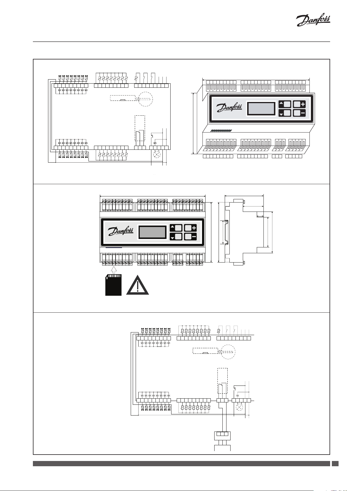
90 mm
Installation Guide CCR2
-
Temperatur-sensorer
Udgang: aktuatorer 1 … 8
Udgang: aktuatorer 1 … 8
Triac-ydelse
C
V2 V3 V4 V5 V6 V7 V8
V1
temperatur-sensorer
S1 … S8
M S1 S2 S3 S4 S5 S6 S7 S8
CCR
CCR
temp.
sensor
desinf.
S0
M B1 M B2 M M A
S0 B
RS 485
start
stop
desinf.
ModBus
do BMS
Fbus
158.5 mm
C
V1 V2 V3 V4 V5 V6 V7 V8
M S1 S2 S3 S4 S5 S6 S7 S8 M B1 M B2 M M AS0 B
C
Udgang: aktuatorer 9 … 16
Fig. 4 Kabelfør ing
CCR2
CONTROLLER
V13
V10V9
Triac-ydelse
V11 V12
V15 V16
V14
M S9 S10 S11 S12 S13 S14 S15 S16
temperatur-sensorer
S9 … S16
CCR2 - CONTROLLER
SD
FLASH
CARD
NO T1T20V 0V 24V
C
NC
Til ECL. Tving
signal til
desinfektion.
(Relæomstillingsydelse)
Til næste CCR 2
for parallel eller
serie forbindelse
ALARM
Forsynings-
spænding
24 VAC
158.5mm
Do not install or
remove SD card when
connected to the
current.
CCR2 - CONTROLLER
V13
V10V9
V15 V16
V11 V12
C M S9 S10 S11 S12 S13 S14 S15 S16
V14
58 mm
31 mm
10
90 mm
35 mm
90 mm
C
35 mm
62 mm
NO T1T20V 0V 24V
NC
Fig. 5 Mål og m onteringer på DIN - relæ 35 mm
CCR
CCR
Triac-ydelse
C
V2 V3 V4 V5 V6 V7 V8
V1
S1 … S8
M S1 S2 S3 S4 S5 S6 S7 S8
temp.
sensor
desinf.
S0
M B1 M B2 M M A
S0 B
RS 485
start
stop
Fbus
desinf.
ModBus
do BMS
CCR2
CONTROLLER
V13
V10V9
C
Udgang: aktuatorer 9 … 16
Triac-ydelse
Fig. 6 CCR2 - forbi ndelse til ECL
Heating Solutions VI.D1.E2.1R SMT/SI
V11 V12
V15 V16
V14
M S9 S10 S11 S12 S13 S14 S15 S16
Temperatur-sensorer
S9 … S16
NO T1T20V 0V 24V
C
NC
parallel eller
serieforbindelse
Transistor-ydelse
1 2 3
ECA9010
Til næste
CCR 2 for
ALARM
Forsynings
spænding
24 VAC
2727
Page 28

Installation Guide CCR2
C
V1
V2 V3 V4 V5 V6 V7 V8
CCR2
V10V9
V11 V12
C
C
V1
V2 V3 V4 V5 V6 V7 V8
CCR2
V10V9
V11 V12
C
C
V1
V2 V3 V4 V5 V6 V7 V8
CCR2
V10V9
V11 V12
C
C
V2 V3 V4 V5 V6 V7 V8
V1
CCR2
V10V9
V11 V12
C
C
V2 V3 V4 V5 V6 V7 V8
V1
CCR2
V10V9
V11 V12
C
V13
V15 V16
V14
V13
V15 V16
V14
V13
V15 V16
V14
V13
V15 V16
V14
V13
V15 V16
V14
M S1 S2 S3 S4 S5 S6 S7 S8
This is Master; CCR Sys: Sequence
StartDis: S0 or S0 + PRG
M S9 S10 S11 S12 S13 S14 S15 S16
M S1 S2 S3 S4 S5 S6 S7 S8
This is Slave;
M S9 S10 S11 S12 S13 S14 S15 S16
M S1 S2 S3 S4 S5 S6 S7 S8
M S9 S10 S11 S12 S13 S14 S15 S16
M S1 S2 S3 S4 S5 S6 S7 S8
M S9 S10 S11 S12 S13 S14 S15 S16
M S1 S2 S3 S4 S5 S6 S7 S8
M S9 S10 S11 S12 S13 S14 S15 S16
StartDis: B1
This is Slave; CCR Sys: Sequence
StartDis: B1
This is Slave; CCR Sys: Sequence
StartDis: B1
This is Slave; CCR Sys: Sequence
StartDis: B1
TEMP.S0
M B1 M B2 M M A
S0 B
NO T1T20V 0V 24V
C
NC
1 2 3
ECA9010ECL XXX
M B1 M B2 M M A
S0 B
CCR Sys: Sequence
NO T1T20V 0V 24V
C
NC
M B1 M B2 M M A
S0 B
NO T1T20V 0V 24V
C
NC
M B1 M B2 M M A
S0 B
NO T1T20V 0V 24V
C
NC
M B1 M B2 M M A
S0 B
NO T1T20V 0V 24V
C
NC
C
V1
V2 V3 V4 V5 V6 V7 V8
CCR2
V10V9
V11 V12
C
C
V1
V2 V3 V4 V5 V6 V7 V8
CCR2
V10V9
V11 V12
C
C
V1
V2 V3 V4 V5 V6 V7 V8
CCR2
V10V9
V11 V12
C
C
V2 V3 V4 V5 V6 V7 V8
V1
CCR2
V10V9
V11 V12
C
C
V2 V3 V4 V5 V6 V7 V8
V1
CCR2
V10V9
V11 V12
C
V13
V15 V16
V14
V13
V15 V16
V14
V13
V15 V16
V14
V13
V15 V16
V14
V13
V15 V16
V14
M S1 S2 S3 S4 S5 S6 S7 S8
This is Master; CCR Sys: Sequence
StartDis: S0 or S0 + PRG
M S9 S10 S11 S12 S13 S14 S15 S16
M S1 S2 S3 S4 S5 S6 S7 S8
This is Slave;
M S9 S10 S11 S12 S13 S14 S15 S16
M S1 S2 S3 S4 S5 S6 S7 S8
M S9 S10 S11 S12 S13 S14 S15 S16
M S1 S2 S3 S4 S5 S6 S7 S8
M S9 S10 S11 S12 S13 S14 S15 S16
M S1 S2 S3 S4 S5 S6 S7 S8
M S9 S10 S11 S12 S13 S14 S15 S16
StartDis: S0 + B1
This is Slave; CCR Sys: Sequence
StartDis: S0 + B1
This is Slave; CCR Sys: Sequence
StartDis: S0 + B1
This is Slave; CCR Sys: Sequence
StartDis: S0 + B1
TEMP.S0
M B1 M B2 M M A
S0 B
NO T1T20V 0V 24V
C
NC
1 2 3
ECA9010ECL XXX
TEMP.S0
M B1 M B2 M M A
S0 B
CCR Sys: Sequence
NO T1T20V 0V 24V
C
NC
TEMP.S0
M B1 M B2 M M A
S0 B
NO T1T20V 0V 24V
C
NC
TEMP.S0
M B1 M B2 M M A
S0 B
NO T1T20V 0V 24V
C
NC
TEMP.S0
M B1 M B2 M M A
S0 B
NO T1T20V 0V 24V
C
NC
Fig. 7 CCR2 - forbi ndelse til CCR2: serieforbinde lse med en S0 - føler
TEMP.S0
C
V1
V2 V3 V4 V5 V6 V7 V8
CCR2
V10V9
V11 V12
C
C
V1
V2 V3 V4 V5 V6 V7 V8
CCR2
V10V9
V11 V12
C
C
V1
V2 V3 V4 V5 V6 V7 V8
CCR2
V10V9
V11 V12
C
C
V1
V2 V3 V4 V5 V6 V7 V8
CCR2
V10V9
V11 V12
C
C
V1
V2 V3 V4 V5 V6 V7 V8
CCR2
V10V9
V11 V12
C
V13
V15 V16
V14
V13
V15 V16
V14
V13
V15 V16
V14
V13
V15 V16
V14
V13
V15 V16
V14
M S1 S2 S3 S4 S5 S6 S7 S8
This is Master; CCR Sys: Paralell
StartDis:
M S9 S10 S11 S12 S13 S14 S15 S16
1 2 3
ECA9010ECL XXX
M S1 S2 S3 S4 S5 S6 S7 S8
This is Slave;
M S9 S10 S11 S12 S13 S14 S15 S16
M S1 S2 S3 S4 S5 S6 S7 S8
This is Slave; CCR Sys: Paralell
M S9 S10 S11 S12 S13 S14 S15 S16
M S1 S2 S3 S4 S5 S6 S7 S8
This is Slave; CCR Sys: Paralell
M S9 S10 S11 S12 S13 S14 S15 S16
M S1 S2 S3 S4 S5 S6 S7 S8
This is Slave; CCR Sys: Paralell
M S9 S10 S11 S12 S13 S14 S15 S16
M B1 M B2 M M A
S0 B
S0 or S0 + PRG
C
NC
M B1 M B2 M M A
S0 B
CCR Sys: Paralell
StartDis: B1
C
NC
M B1 M B2 M M A
S0 B
StartDis: B1
C
NC
M B1 M B2 M M A
S0 B
StartDis: B1
C
NC
M B1 M B2 M M A
S0 B
StartDis: B1
C
NC
NO T1T20V 0V 24V
NO T1T20V 0V 24V
NO T1T20V 0V 24V
NO T1T20V 0V 24V
NO T1T20V 0V 24V
Fig. 8 CCR2 - forbi ndelse til CCR2: serieforbinde lse med individuel S0 - føle r
TEMP.S0
C
V1
V2 V3 V4 V5 V6 V7 V8
CCR2
V10V9
V11 V12
C
C
V1
V2 V3 V4 V5 V6 V7 V8
CCR2
V10V9
V11 V12
C
C
V1
V2 V3 V4 V5 V6 V7 V8
CCR2
V10V9
V11 V12
C
C
V1
V2 V3 V4 V5 V6 V7 V8
CCR2
V10V9
V11 V12
C
C
V1
V2 V3 V4 V5 V6 V7 V8
CCR2
V10V9
V11 V12
C
V13
V15 V16
V14
V13
V15 V16
V14
V13
V15 V16
V14
V13
V15 V16
V14
V13
V15 V16
V14
M S1 S2 S3 S4 S5 S6 S7 S8
This is Slave; CCR Sys: Paralell
StartDis:
M S9 S10 S11 S12 S13 S14 S15 S16
1 2 3
ECA9010ECL XXX
M S1 S2 S3 S4 S5 S6 S7 S8
This is Slave;
StartDis: S0 or S0 + PRG
M S9 S10 S11 S12 S13 S14 S15 S16
M S1 S2 S3 S4 S5 S6 S7 S8
This is Slave; CCR Sys: Paralell
StartDis: S0 or S0 + PRG
M S9 S10 S11 S12 S13 S14 S15 S16
M S1 S2 S3 S4 S5 S6 S7 S8
This is Slave; CCR Sys: Paralell
StartDis: S0 or S0 + PRG
M S9 S10 S11 S12 S13 S14 S15 S16
M S1 S2 S3 S4 S5 S6 S7 S8
This is Slave; CCR Sys: Paralell
StartDis: S0 or S0 + PRG
M S9 S10 S11 S12 S13 S14 S15 S16
M B1 M B2 M M A
S0 B
S0 or S0 + PRG
NO T1T20V 0V 24V
C
NC
TEMP.S0
M B1 M B2 M M A
S0 B
CCR Sys: Paralell
NO T1T20V 0V 24V
C
NC
TEMP.S0
M B1 M B2 M M A
S0 B
NO T1T20V 0V 24V
C
NC
TEMP.S0
M B1 M B2 M M A
S0 B
NO T1T20V 0V 24V
C
NC
TEMP.S0
M B1 M B2 M M A
S0 B
NO T1T20V 0V 24V
C
NC
Fig. 9 CCR2 - forbi ndelse til CCR2: parallelforbin delse med en S0 - føler Fig. 10 CCR2 - forbind else til CCR2: parallelforbinde lse med individuel S0 - føle r
28
SMT/SI VI.D1.E2.1R Heating Solutions
Page 29

Installation Guide CCR2
POLSKIDANSK
1. Produktbeskrivelse
2. Tekniske data
CCR2 er en regulator, der anvendes til
optimering af den termiske desinfektionsproces
i varmtvandsanlæg med funktioner, som f.eks.
temperaturmåling og overvågning af cirkulationen
i varmtvandsanlæg. Regulatoren er forbundet til
Temperaturføler (S0, S1 … S16) Pt1000, S0 - type ESMC/ESM11, S1 … S16 – type ESMB
Temperaturområde (måling) –20 °C … +120 °C
Målingsnøjagtighed ± 0,1 K
Indgange: B1 og B2 Fri kontakt (5 V 1 mA)
Antal manøvreventiler (stigestrenge) 16
Udgangssignal til aktuatorer (type Triac) 24 V vekselstrøm mak s. 1 A
Alarmsignaludgang (type Triac) 24 V vekselstrøm mak s. 1 A
Relæudgang 0 … 24 V vekselstrøm/jævnstrøm mak s. 1 A
OC - udgang (t ype Transistor) 0 … 20 V jævnstrøm NPN Åben opsamler maks. 200 mA
Hukommelseskorttype (inkluderet) SD (512 MB inkluderet)
Maksimumhukommelseskort 2 GB
Timer: realtidsur Indbygget batteri – levetid 10 år
Omgivelsestemperatur 0 … 50 °C
Transporttemperatur –10 … +60 °C
IP - grad IP 20
Strømforsyning 24 V vekselstrøm
Strømforbrug 6 VA
Vægt 0,9 kg
Montage DIN - skinne 35 mm
termoaktuatorer af typen TWA - A og
erntemperaturfølere PT1000, type ESMB,
der er installeret på hver enkelt termostatisk
cirkulationsventil af typen MTCV (Multifunctional
Thermostatic Circulation Valve).
3. Montage
4. Sådan tændes regulatoren
CCR2 - regulatoren er monteret i teknikboksen på
DIN - skinnen 35 mm for at lette adgangen til den.
Boksen med DIN - skinnen skal monteres på væggen
(transformatorstation eller kedelrum) så tæt på
varmekilden som muligt. DIN - skinne og boks
Før regulatoren tændes første gang, skal alle kabler
ernes, og der skal sluttes en 24 V vekselstrømkilde
til det afbrudte strømstik. Benyt et voltmeter til
måling af spændingen på strømkabelstikket, før
den sluttes til regulatoren.
Hvis spændingen er korrekt:
1. Læs vejledningen, inden du betjener regulatoren.
2. Fjern alle kabler.
3. Slut strøm til transformatoren
(ikke tilsluttet CCR2).
4. Tænd for strømmen til transformatoren.
5. Godkendt strøm – 24 V.
6. Sæt transformatorkablet i CCR2 - indgangen.
ikke inkluderet. Det anbefales at montere en
standard 24 V vekselstrømstransformator i den
samme boks som CCR2 (ikke forsyning). Når CCR2
er sluttet til strøm, må et SD - kort ikke installeres
(eller ernes). Den skal afbrydes (risiko for tab af data)
Regulatoren bør vise navnet og software - versionen
- CONTROLLER START MENU – display i henhold til
punkt 5.
Inden der forbindes stik til regulatorens indgangs
- og udgangsforbindelser:
1. indstilles alle parametrene på regulatoren
2. skal det kontrolleres, at der ikke er udvendig
spænding på temperaturfølerstikkene
3. skal det kontrolleres, at spændingen på
relækontakterne ikke er for høj (maks. 24 V
vekselstrøm).
.
Heating Solutions VI.D1.E2.1R SMT/SI
2929
Page 30

Installation Guide CCR2
5. Regulatorens startmenu
Startproces
Når det SD - kort, som regulatoren har registreret,
er blevet tændt, og hukommelsen på kortet er blevet
kontrolleret, vil følgende ske.
Hvis kortet er placeret korrekt, vil regulatoren
kontrollere de ler, der er på kortet:
• adgang
• one set
• allset
Hvis ovenstående ler ndes, vil regulatoren spørge,
om de skal anvendes eller ernes.
Hvis der ikke er nogle ler (nyt kort, anvendt for
første gang), vil der ikke forekomme en anmodning.
Den næste regulator opretter automatisk en mappe
med følgende ler:
• mappeACCESS:
tillad ændring af adgangskode til menuen
(oplysninger kan fås ved henvendelse eller
www.danfoss.com)
Nr. LCD Di splay READING DESCRIP TION
1 Danfoss
CCR – 2.60
2 SD Free
… ..
3 SD Free
512 MB
4 NO
SD CARD!
5 AccesCod
Read?
6 AccesCod
DONE!
7 AccesCod
Aborted!
8 OneSet
Read?
9 OneSet
DONE!
10 OneSet
Aborted!
11 AllSet
Read?
12 AllSet
DONE!
13 AllSet
Aborted!
14 72254
123456
15 Thu On
12: 59: 32
16 10/9/06
12: 59: 32
Velkomstmenu
Diagnose: ledig hukommelse på SD - kor t
Ledig hukommelse i MB
Intet SD - kort i CCR2
Kun når der ikke er et kort i CCR2.
Ønsker du at ændre adgangskoden til regulatoren?
Tryk samtidigt på “+” og “▼” for at ændre adgangskodeindstillingerne.
Forespørgsel forekommer kun, hvis den ændrede kode til len er på SD - kortet. Fil: ACCESS.
Ændringer udført!
Informationen vises kun, hvis SD-kortet omfatter den ændrede kode til len: ACCESS og ændringerne
blev bekræftet
Nulstilling ikke udført.
Oplysninger forekommer kun, hvis den ændrede kode til len er på SD - kortet:
ACCESS og ændringer ignoreret.
Vil du ændre alle indstillingerne og oprette nye indstillinger på en pc? Tryk samtidigt på “+” og ”▼”
for at foretage ændringer.
Forespørgsel forekommer kun, hvis CCR2 nder nye indstillinger på SD - kortet, der er prædenerede
på en pc: SETTING. Bemærk! Anbefales kun til servicepersonale.
Ændringer udført!
Oplysninger forekommer kun, hvis SD - kortet indeholder en l med prædenerede SETTINGS:
og ændringer blev bekræftet.
En ny indstilling blev afbrudt!
Oplysninger forekommer kun, hvis SD - kortet indeholder en ændret l: SE TTING og ændringer
ignoreret.
Hvis du ønsker at anvende data fra l: allset fra SD - kort og ændre alle indstillinger i CCR2?
Tryk samtidigt på “+” og “▼” for at ændre alle indstillingerne.
Forespørgsel forekommer altid kun fra regulatorens anden kørsel med SD - kort.
AllSet – kan anvendes til at erne indstillinger fra CCR2 til en anden CCR2.
CÆndringer udfør t!
Oplysninger forekommer kun, når SD - kortet indeholder en AllSet - l og ændringerne blev bekræftet.
Ændringer af Allset blev afbrudt
Oplysninger forekommer kun, når SD - kortet indeholder en AllSet - l, og ændringerne blev ignoreret.
CCR2’s serienummer og sof twarenummer.
Koder anvendt til tjenester.
Ugedag: man, tir, ons, tor, fre, lør, søn.
Status for arbejdsplanen:
“On”: desinfektion tilladt i fastlagt plan;
“O”: desinfektion ikke tilladt i fastlagt plan
12: 59: 32 realtid: time, minut, sekund
Realdata
Realtid: time, minut, sekund
• mappeDATA:lmedregistreringsdata
• mappeSETTINGSmedler
- allset: l med indstillinger. Hver gang
regulatoren tændes, arkiveres
indstillingsparametrene. Denne funktion
opretter en godkendelseshistorie for alle
indstillinger
- arch.set: l med arkivering af alle indstillinger.
Når regulatoren tændes for anden gang med
den ovennævnte protokoll, starter
anmodningsproceduren til indstilling af
ændring eller afbrydelse.
Displayoplysninger under startprocessen
Når CCR2 - regulatoren tændes, viser LCD - displayet
automatisk startmenuen. Nedenstående tabel viser
de forskellige oplysninger og ændringsmulighederne
under CCR2’s drift.
30
SMT/SI VI.D1.E2.1R Heating Solutions
Page 31

Installation Guide CCR2
6. Regulatorens visningsmenu
Når opsætningen er fuldendt, vises visningsdisplayet
på skærmen.
09 - 10 - 06
12: 59: 32
Nr. LCD - display BESKRIVELSE AF VISN ING
17 10/9/06
12: 59: 32
18 AC: 0117
… … … …
19 DayToEnd
148
20 In B1 - M
… … .
21 In B2 - M
… … …
22 Out T1 0V
… … …
23 Alert T2
… … ..
24 Rel C - NO
… … .
25 Disinfec
… … … … ..
26 Disin.Is
… … … ..
27 Dis.SetT
… °C
28 Adv.Fact
… .%
29 GroupNr
… … ..
Det aktuelle tidspunkt og dato.
Oplysningsdisplay skiftevis med oplysninger om ak tuel dato f.eks: lør – planlagt status og tidspunkt.
Display præsenteret ovenfor. Data anvendt i arkivlen.
“AC: 0117” - Hvor stor en mængde data kan lagres på SD - kortet:
De registrerede data angives af en tæller, f.eks..0117 – 117 registreringer blev udført.
Når antallet overstiger 9999, starter tælleren fra 0000.
Skiftevis med arkiveringsfunktion InProces – data er registreret.
Skiftevis med arkiveringsfunktion Disable – data er ikke registreret.
Skiftevis med NoSDcard – intet SD - kort i CCR2
Hvor stor en mængde data kan lagres pr. dag på hukommelseskortet (med aktuelle indstillinger)
Indgangsstatus B1 - M
Open - indgang B1 åben
Close – indgang B1 lukket for M
Luk (genvej B1 - M) kan anvendes til påbegyndelse af desinfektion (Se “DisSourc” i installationsmenuen)
Funktionen benyt tes i parallel - og serieforbindelser.
Indgangsstatus B2 - M
Open - indgang B2 åben
Close – indgang B2 lukket for M
Luk (genvej B2 - M) altid afsluttet desinfektionsproces. Afslutning på desinfektionsprocessen kan udføres
automatisk (se: Install Menu – Denne er master) eller manuelt, hvis det er nødvendigt at standse processen.
Når det gøres manuelt, vil der på LCD stå – disinfection fault.
Udgangsstatus T1 - 0V (åben opsamler)
Open – T1 åben
Close – T1 lukket.
T1 - signalet anvendes til at give tilladelse til den næste CCR2 i parallel - eller serieforbindelsen
(se “CCR Sys” i installationsmenuen)
Statusalarm for udgang T2 (triack - udgang)
Active – signal 24 V vekselstrøm på T2 - udgangen
NotActive – signal 0 V på T2 - udgangen
T2 anvendes som alarmsignal i nedenstående situationer:
- følerfejl: f.eks. genvej i følerkredsløb (SensFaul)
- når desinfektionsprocessen ik ke blev gennemført i stigestrengen (FaultDis)
- desinfek tionen blev stoppet manuelt af B2 - genvejen
Signalalarmen kan annulleres, når man går ind i alle menuer og efter, at årsagen til fejlen er ernet
(f.eks. ef ter reparation af føler)
Udgangsstatus C - NO (ledig kontaktrelæstatus: C - NO - NC)
Open - udgang C - NO åben (betyder, at C - NC er lukket)
Close - udgang C - NO lukket (betyder, at C - NC er åbent)
Ledigt kontaktrelæ er lukket, når CCR2 anmoder om høje temperaturer fra ECL eller anden styring
af varmekilde til for tsættelse af desinfektionen. Denne udgang kan også anvendes til udvendige
signaler til angivelse af desinfek tionsprocessen. Der er behov for et suppor trelæ.
Er desinfek tion tilladt?
Valg mellem:
Enable – desinfektion er tilladt
Disabl e – desinfektion er slukket under indstillinger: BASIC MENU - punkt: “Disinfec Disable” nr.
30, kapitel 8.
Kører desinfektionen for øjeblikket?
Valg mellem:
InProces – desinfek tionen kører;
Finished – desinfek tionen er udført.
Den indstillede desinfektionstemperatur.
Valgområderne ses i nedenstående tabel.
Beregnet interval for desinfektionens forløb, opdateres efter hver enkelt opdelingsperiode.
Antal stigestrenge i den aktuelle desincerede gruppe.
Hvis der ikke er foretaget en opdeling, er det te det samlede antal stigestrenge. Valgmulighederne
opdeler stigestrengene i grupper under desinfek tionen, eller anvendes i INSTALL MENU, nummer 39,
kapitel 9: Funktion: Når opdeling anvendes, kan desinfek tionsprocessen accelerere i kredsløbsanlæg
med meget varmt vand.
Sat On
12: 59: 32
Ved at trykke på “+” - tasten vises det næste
visningsdisplay. “ - ” - tasten tænder for det forrige
visningsdisplay. Når der trykkes på “▲” - tasten,
forsvinder visningsdisplayet, og ACCES CODE menuen fremkommer som beskrevet I kapitel 7.
Når menuen forlades, vises det første visningsdisplay.
I tabellen nedenfor vises en liste over visninger
og mulige visningsoptioner.
Heating Solutions VI.D1.E2.1R SMT/SI
3131
Page 32
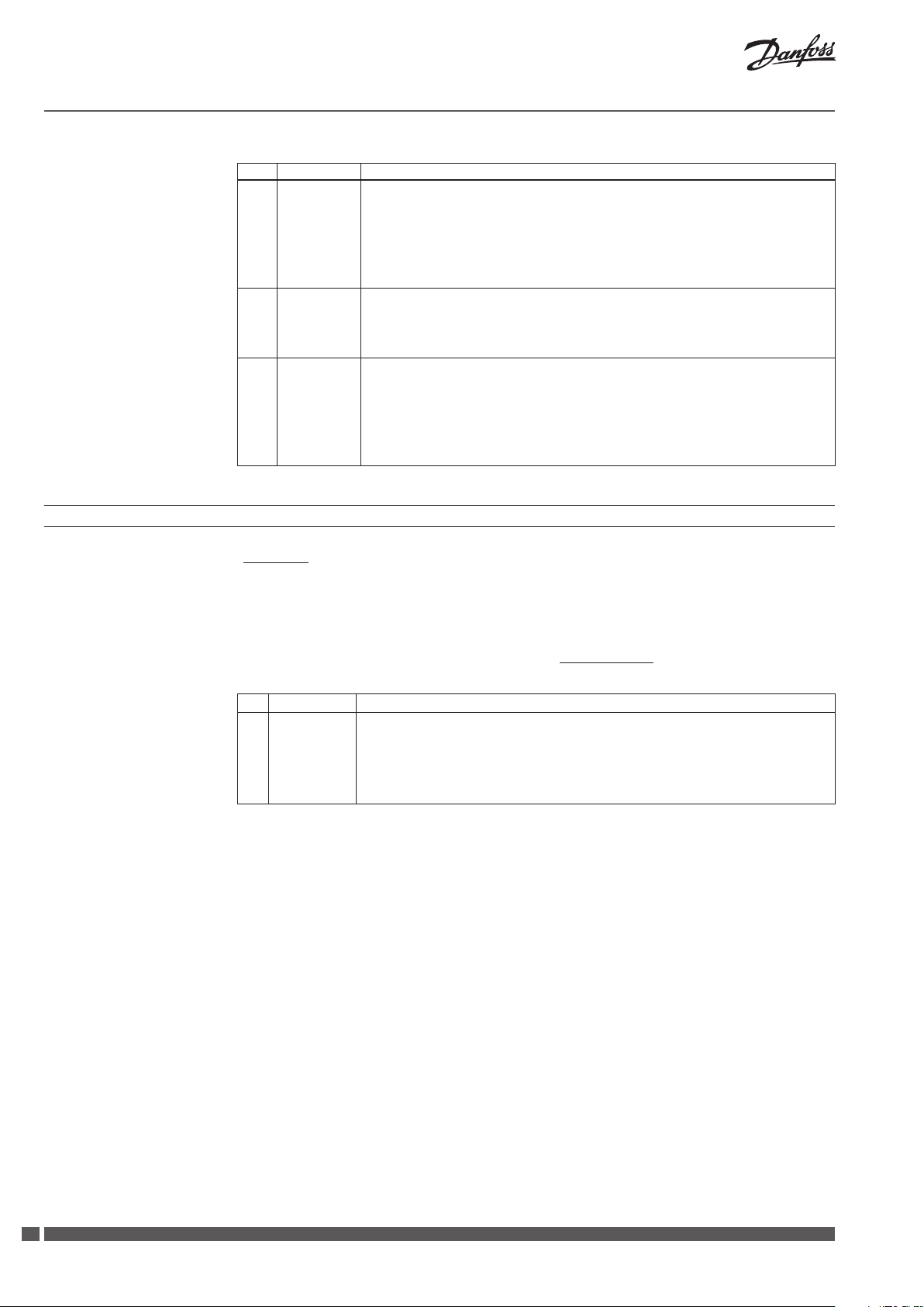
Installation Guide CCR2
Nr. LCD - display BESKRIVELSE AF VISN ING
30 Sensor 0
… °C
31 Valve 1
… … %
32 R1 … h Riser R1 – statusoplysninger for stigestreng:
7. Adgangskode til menuen – adgang til indstillinger
Føler S0 - temperatur. De samme visninger gælder for følerne S1 ... S16.
Disse symboler angiver, at den reelle temperatur i systemet overskrider den ønskede temperatur.
Det ønskede område er fastsat i punkt 52-55 i menuen INSTALL. Funktionen anvendes til
temperaturalarm.
Hvis L eller H ikke vises, er den reelle temperatur inden for det ønskede indstillingsområde.
Tryk på “+” for at skifte mellem følere. Eller det k an forekomme:
Open – ingen føler eller bryderkontaktor
Closed – genvej til jord i følerkredsløbet
SStatus for ventil: V1 … V16.
Tryk på “+” for at skifte mellem ventiler. Eller en af følgende:
On – åben, ventil V1 er for øjeblikket i drift, (når PWM tages i betragtning).
O – lukket, ventil V1 er for øjeblikket ude af drift (når PWM tages i betragtning).
… ..% – valve open ratio – procentdel af opfyldning af PWM - funk tionen (0 … 100 % intervaller af 10 %).
R1 … h – resterende overhedningstid før fuldendt desinfektionsproces for den pågældende stigestreng
(nedtællingstimer). Når processen er fuldfør t, nulstilles timeren til starttid.
Disin – desinfektion kører for øjeblikket for stigestreng R1,
HoldDis – desinfektion afbrydes for øjeblikket for stigestreng R1 efterfølgende en deling af gruppen,
EndDis in – desinfektionen blev udført for stigestreng R1
FaulDis – desinfektion blev ikke udført for stigestreng R1
SensFaul – temperatur følerfejl i denne stigestreng
I R
EADING MENU
trykkes på pil op - tasten “▲”, og
adgangskoden indtastes (tre cifre), hvorefter der
opnås adgang til den ønskede indstillingsgruppe.
“+/ - “ - tasterne ændrer talværdierne i adgangskoden,
“▲/▼” - tasterne ytter markøren gennem kodens
cifre. Tryk på “▲” - piletasten efter det sidste cier
i koden, for at få adgang til den ønskede
Nr. LCD - display ACCES CODE - FUNKTIO NSBESKRIVELSE
33 AcceCode
***
Adgangskoder til regulatorens indstillingsmenuer: Tilgængelige menuer:
– Basic menu (kode: 359), grundlæggende indstillingsmenu
– Install menu (kode: 427). avancerede indstillinger
– Schedule menu (kode 760). Indstillinger for ugentligt fastlagt desinfektionsprocesplan
– Real Time menu (kode 576). Indstilling af realtidsur og dato
– Ved at trykke på “▲” - piletasten re gange uden at indtaste nogen kode opnås adgang til ”SD Card
Exchange”. SD - kortet kan tages sikker t ud af CCR2 (dataregistreringsprocessen afbr ydes).
Adgangskoderne er standard for de enkelte menuer.
Det er muligt at ændre adgangskoderne ved at
angive nye koder via SD - hukommelseskortet og
genstarte regulatoren. Der kan fås en mere detaljeret
vejledning ved henvendelse.
Regulatorens indstillinger kan indtastes vha.
tastaturet eller generelt via SD - hukommelseskortet
(der kræves genstart af regulatoren) Der kan fås
yderligere oplysninger ved henvendelse.
indstillingsgruppe. Hvis koden ikke er korrekt,
viser displayet: SD Card Exchange – hvilket
betyder, at SD - kortet kan tages sikkert ud af
CCR2 (dataregistreringsforløbet er afbrudt).
Indstillingsmenuen lukkes automatisk efter re
minutters inaktivitet, og displayet vender tilbage
til READING MENU.
Producenten forbeholder sig ret til at ændre
regulatorens indstillinger og visninger under
produktionen for at forbedre betjeningen og
funktionaliteten. På Danfoss’ websted ndes
en opdateret liste over indstillinger for den
pågældende software - version. Nye indstillinger
kan automatisk opgradere CCR2 gennem
SD - hukommelseskortet (der kræves genstart
af regulatoren).
32
SMT/SI VI.D1.E2.1R Heating Solutions
Page 33

Installation Guide CCR2
8. Indstillinger for basismenuen (KODE 359)
I ACCES CODE - menuen angives koden: 359
(procedure i kapitel 7). I tabellen nedenfor vises
detaljerede oplysninger for Basic menu. Piletasterne
“▲/▼” ytter menuvinduerne, “+/ - “ - tasterne
ændrer værdierne i vinduet, der er valgt vha.
pilene. Tryk på pil op - tasten “▲” efter ændring
den seneste menu, for at forlade indstillingsmenuen.
Nr. LCD display BASIC MEN U - FUNKTIONSBESKRIVELSE
34 Basic
Menu
35 Disinfec
…
36 Dis.Temp
… °C
37 DisinTime
… h … min
38 Ecs?
+ YES
ESC?
+ YES
Oplysninger om menuen: basis
Er desinfek tion tilladt?
Mulige valg:
- Enable – desinfektion er tilladt
- Disabl e – desinfektionen slukkes
Indstil desinfektionstiden i stigestrengene.
Desinfektionsnedtællingen sker uafhængigt for hver enkelt stigestreng. Den anbefalede maksimum - og
minimumtid afhænger af desinfektionstemperaturen, og bør vælges ud fra tabellen i kapitel 13.
Indstil desinfektionstiden i stigestrengene.
Desinfektionsnedtællingen sker uafhængigt for hver enkelt stigestreng. Den anbefalede maksimum - og
minimumtid afhænger af desinfektionstemperaturen, og bør vælges ud fra tabellen i kapitel 13.
Forlad vinduerne fra Basic Menu. Indtast “+” for at lukke indstillingen, ellers lukker basismenuen
automatisk efter 4 minutter.
9. Indstillinger for Install menu (kode: 427)*: anbefales kun til servicepersonale
Indstillingsmenuen lukkes automatisk efter
4 minutters inaktivitet. The setting menu is
closed automatically after 4 minutes of inactivity.
Bemærk!
af
Når man går ind i Basic Menu, afbrydes
desinfektionsprocessen og alarmsignalet.
I ACCES CODE - menuen angives koden: 427
(procedure i kapitel 7). I tabellen nedenfor vises
detaljerede oplysninger for Install menu.
Piletasterne “▲/▼” ytter menuvinduerne, “+/ - “
- tasterne ændrer værdierne i vinduet, der er
valgt vha. pilene. Tryk på pil op - tasten “▲” efter
ændring af den seneste menu, for at forlade
Nr. LCD Disp lay I NSTALL MENU - FUNKTI ONSBESKRIVE LSE
39 INSTALL
Menu
40 Disinfec
…
41 Dis.Temp
… °C
42 DisinTime
… h … min
43 Cir.Temp
… °C
44 Divide
…
Oplysninger om menuen: installation
Anbefalet til service.
Er desinfek tion tilladt?
Mulige valg:
- Enable – desinfektion er tilladt
- Disabl e – desinfektionen slukkes
Fabrik sindstill ing: aktiver et
Indstil desinfektionstemperaturen. Desinfektionen påbegyndes, når temperaturen på føler S0 overstiger
den indstillede temperatur. Når den indstillede temperatur på en stigestrengsføler (S1 ... S16) overstiges,
udløses en desinfektionsnedtælling for den pågældende stigestreng.
Fabrik sindstill ing: 65 °C
Indstil desinfektionstiden i stigestrengene.
Desinfektionsnedtællingen sker uafhængigt for hver enkelt stigestreng. Den anbefalede maksimum - og
minimumtid afhænger af desinfektionstemperaturen, og bør vælges ud fra tabellen i kapitel 13.
Fabrik sindstill ing: 15 min
Elektronisk styret cirkulationstemperatur ef ter desinfektion i stigestrengen. CCR2 kan bevare den
krævede cirkulationstemperatur i stigestrengen efter desinfektionsprocessen. Funktionen anbefales
kun til manøvreventiler med aktuatorer (PI - styresignal). For selvvirkende ventiler som MTCV (med basis
termostatelement) er den anbefalede indstilling 5 °C .
Fabrik sindstill ing: 5 °C
Opdeling af stigestrenge i to grupper:
- Enable – når desinfektionsprocessen er langsommere end det indstillede forløb i MinAdvan i position 42,
- Disable – slukket uafhængigt af desinfek tionsforløbet.
Fabrik sindstill ing: aktiver et
indstillingsmenuen. Indstillingsmenuen lukkes
automatisk efter 4 minutters inaktivitet.
Når man går ind i menuindstillinger, afbrydes
desinfektionsprocessen og alarmsignalet.
Heating Solutions VI.D1.E2.1R SMT/SI
3333
Page 34

Installation Guide CCR2
Nr. LCD Disp lay I NSTALL MENU - FUNKTI ONSBESKRIVE LSE
45 Div.Time
… min
46 MinAdvan
… %
47 Riser Nr
48 This is
… ..
49 CCR Sys
… … .
50 Int.Time Integrationstiden for desinfektionstemperaturen (og cirkulationstemperatur) udgør grundlaget for
51 Prop.Fac Opnået kontrol med desinfektionstemperaturen (og cirkulationstemperatur) udgør grundlaget
52 Req.Temp
…ºC
53 Dif. Temp
in + …. ºC
54 Dif.Temp
in - … ºC
55 AlarmDLY
… min
…
Gruppeopdelingsperiode. CCR2 beregner trinvist det gennemsnitlige desinfektionsforløb i det
minutantal, der angives her, fra det øjeblik, hvor desinfektionen starter. Derefter bestemmer den,
om stigestrengene skal inddeles i grupper eller ej.
Fabrik sindstill ing: 20 min
Minimum gennemsnitlig desinfektionsforløb angivet i procent beregnet ud fra gruppeopdelingstiderne.
Hvis denne overstiges, opdeles stigestrengene ikke i grupper. Hvis desinfek tionsforløbet er lavere end
20 %, opdeles stigestrengene i grupper.
Fabrik sindstill ing: 25 %
Antal stigestrenge, der er forbundet til CCR2.
Fabrik sindstill ing: 16
Anvendt funk tion: Når CCR2 er forbundet med ECL (en anden regulator) eller med en anden CCR2.
Bestemmer, hvorvidt CCR2 skal fungere som master eller slave – kun gyldig i parallel - eller serieforbindelse
med en anden CCR2 og forbindelse til f.ek s. ECL.
Eksempel: en master og to slaver
Hvis desinfektionen ikke aktiveres, vil relæ (C/NC /N0) lave en genvej til C og NC. Hvis desinfektionen
aktiveres, vil relæ (C/NC/N0) ændre genvej til C og N0 Denne genvej C/NC gør det muligt for CCR2 at bevare en kontinuerlig høj forsyningstemperatur vha.
ECL - regulatoren eller en anden regulator. Tilgængelige indstillinger:
Master – bevar genvejen, (C/NC) indtil udført desinfektion er bekræftet. Processen kommer fra seneste
CCR2 (slave) gennem genvejen B2 til M (fejl til stel).
Slave – bevar genvejen, (C/NC) kun i denne CCR2 (slave) indtil udført desinfektion er kontrolleret af
denne CCR2.
Fabrik sindstill ing: Slave (altid n år man bruger CCR 2 alene)
Anvendt funk tion: når CCR2 er forbundet med en anden CCR2. Store udvidede anlæg.
Parallel – desinfek tion udføres på samme tid. Hvis der forekommer et desinfektionssignal, bliver T1
genvej med M. Dette er et signal til CCR2 om at påbegynde desinfektionen. Parallelfunktionen gør
det muligt at påbegynde desinfektionen i alle CCR2 - regulatorer på samme tid, idet master - CCR2’en
ophæver desinfektionsrækkefølgen for CCR2 - slaven skiftevis for slave 1, der ophæver CCR2 - slave 2
(skema – g. 10 og 11)
Sequen ce – desinfektion trin for trin ( første CCR2 , anden CCR2 osv.)
Hvis der forekommer et desinfektionssignal, starter desinfektionsprocessen kun i den første CCR2 (master)
og efter implementering (udført eller ikke) bliver udgang T1 genvej til M, hvilket gør det muligt at starte
processen i en anden CCR2. Når CCR2 udfører den sidste desinfektion, vil den første CCR2 (master)
sende et signal til ECL (eller en anden regulator), og fors yningsdesinfektionstemperaturen vender
tilbage til komfort temperaturen. (skema på g. 8 og 9)
Fabrik sindstill ing: paralle l
processen i stigestrengene, der styres af MTCV - ventilerne. Jo kortere tid, jo hurtigere vil temperaturen
ændre sig (ingen stabil regulering). Jo længere tid, jo længere reaktion for temperaturændringer
(stabil regulering).
Fabrik sindstill ing: 60 sek
for processen i stigestrengene, der styres af MTCV - ventilerne. Jo højere opnået kontrol, jo større
ventilreak tion (ingen stabil regulering). Jo mindre opnået kontrol tid, jo svagere reaktion for
temperaturændringer (stabil regulering).
Fabrik sindstill ing: 100
Indstil ønsket temperatur i installationen.
Indstillingsområde mellem +10 °C og +100 °C
Denne indstilling er brugt til temperaturalarmoutput når den reelle temperatur i systemet overskrider
øvre og nedre afvigelse talt fra ønsket temperatur.
Fabrik sindstill ing: 55 ºC
Indstil øvre afvigelsestemperatur
talt fra ønsket temperatur. Temperaturalarmoutput indikerer signal når temperaturen overskrider
denne grænse. Indstillingsområde mellem +1 °C og +20 °C
Fabrik sindstill ing: + 10 ºC
Indstil nedre afvigelsestemperatur talt fra ønsket temperatur. Temperaturalarmoutput indikerer signal
når temperaturen falder til under denne grænse Indstillingsområde mellem -1 °C og -20 °C
Fabrik sindstill ing: - 10 ºC
Indstil alarmforsinkelse. Temperaturalarm forsinker når den reelle temperatur overskrider øvre og
nedre afvigelser talt fra ønsket temperatur.
Indstillingsområde mellem 0 minutter og 100 minutter
Fabrik sindstill ing: 10 minutter
34
SMT/SI VI.D1.E2.1R Heating Solutions
Page 35

Installation Guide CCR2
Nr. LCD Disp lay I NSTALL MENU - FUNKTI ONSBESKRIVE LSE
56 Cor
S0 …
… °C
57 Rel.Test
… … … .
58 AlertRel
… …
59 Archiver
60 ArchFreq
61 DisSourc
… … ..
62 BMSAdres CCR2 address in BMS system
63 BMS TYPE Type dataoverførsel:
64 DateForm Datavisningsformat:
…
…
Sensorkalibrering: S0 … S16 i området: ±9,9 °C
Lav ikke kalibrering, hvis sensorkabler er kortere en 10 meter.
Er kablerne længere end 10 meter, brug korrektionsfaktorer fra nedenstående tabel.
Korrektionsfak tor
Total længde
(til hovedkabel)
i meter 0,5 mm
10 - 0,2 - 0,1 - 0,1 - 0,1
15 - 0,5 - 0,3 - 0,2 - 0,1
20 - 0,4 - 0,3 - 0,2 - 0,1
25 - 0,5 - 0,3 - 0,3 - 0,1
30 - 0,6 - 0,4 - 0,3 - 0,2
35 - 0,7 - 0,5 - 0,4 - 0,2
40 - 0,8 - 0,5 - 0,4 - 0,2
45 - 0,9 - 0,6 - 0,5 - 0,2
50 - 1,0 - 0,7 - 0,5 - 0,3
75 - 1,5 - 1,0 - 0,8 - 0,4
100 - 2,0 - 1,4 - 1,0 - 0,5
125 - 2,5 - 1,7 - 1,3 - 0,6
150 - 3,0 - 2,0 - 1,5 - 0,8
kabeldiameter
2
0,75 mm2 1,00 mm2 1,5 mm
2
Fabriksindstilling: 0 °C
Relætest (Triac - udgang)
AUTO – alting fungerer automatisk
V1 … V16 – tvunget signal til ventiludgange V1 … V16
Rel C - NO – tvunget signal til relæ C/NO
T1 Out – tvunget signal til udgang T1 (åben opsamler)
T2 Out – tvunget signal (24 V vekselstrøm) for alarm T2.
Fabriks indstilling: Auto
Alarmudgang (Triac)
StillOn – kontinuerligt alarmsignal: T2 – 24 V vekselstrøm
Pulse – pulsalarmsignal 24 V vekselstrøm hvert sekund
Fabriks indstilling: Puls
Oplysninger om dataarkivering:
aldrig - funktionen slukket,
1 File – data lagres i en l på SD - kortet,
2 Files – data lagres skiftevis i to ler for at forbedre skrivningens pålidelighed. Denne funktion
begrænser betingelser for datalagring (to gange).
Fabriks indstilling: 1 File
ataarkiveringsinterval. Tidsintervallet kan indstilles til alle værdier mellem 10 sekunder og 4 timer.
D
Fabriks indstilling: 1 min
Desinfektionskilder til kørsel af desinfektionen og fortsættelse af processen. Der ndes få
kombinationer, der gør det muligt, at indlede processen på baggrund af et enkelt signal eller i
forhold til mange krævede signaler. Desinfektionen indledes når:
S0 – føler S0 rapporterer en temperatur, der er højere end desinfektionstemperaturen.
B1 – B1 - indgang forkortet til jord,
S0+SCh – føler S0 rapporterer en temperatur, der er højere end desinfektionstemperaturen i
den fastlagte tidsperiode.
B1+SCh – B1 - indgang forkortet til M (jord) i den fastlagte tidsperiode.
SCh - ugentlig plan kører og fortsætter, indtil den er udført, selvom den ig. planen skulle
afslutte den,
S/B0+SCh – B1 - indgangen forkortet til to M (fejl til stel, jord) eller føler S0 rapporterer en
temperatur, der er højere end desinfektionstemperaturen i den planlagte tidsperiode,
S0&B0 – B1 - indgang forkortet til M, og føler S0 rapporterer en temperatur, der er højere end
desinfektionstemperaturen.
S0&B0+SCh - B1 - indgang forkortet til M, og føler S0 rapporterer en temperatur, der er højere
end desinfektionstemperaturen i den planlagte tidsperiode.
Fabriks indstilling: S0
Factor y setting: 1
ModBus 96 (9.600)
ModBus 19 (19.000)
ModBus 38 (38.400)
FBus
Fabriksindstilling: ModBus 96
YY - MM - DD – år, måned, dag
YY - MM - DD – år, måned, dag
DD - MM - YY – dag, måned, år
MM - DD - YY – måned, dag, år
Fabriks indstilling: YY - MM - D D
Heating Solutions VI.D1.E2.1R SMT/SI
3535
Page 36

Installation Guide CCR2
Nr. LCD Disp lay I NSTALL MENU - FUNKTI ONSBESKRIVE LSE
65 CCR2 is
… … .
66 Reset
… … .
67 Ecs?
+ YES
10. SCH indstilling: Indstillinger for menuen weekly schedule programme (kode 760)
Status for CCR2:
Register – fungerer kun som temp eraturmåler
Reg+Dis – fungerer som desinfek tionsregulator med temperaturmåling
Fabrik sindstill ing: Reg+Dis
Nulstil til fabriksindstillinger
Yes – går tilbage til fabriksindstillinger
No – beholder de tilpassede indstillinger
Bemær k! For at afslutte nulstilli ngsproceduren skal CCR3 frakobles og d erefter tilkobles ige n.
Forlad vinduerne fra Install Menu. Indtast “+” for at lukke indstillingen, ellers lukker basismenuen
automatisk efter 4 minutter.
I ACCES CODE - menuen angives koden: 760
(procedure i kapitel 7). Schedule menuen vises
som i skemaet nedenfor.
Piletasterne “▲/▼” ytter menuvinduerne, “+/ - “ -
tasterne
ændrer værdierne i vinduet, der er valgt
vha. pilene.
Nr. LCD - display PRG - SCHEDULE PRO GRAMME MENU - FUNKTIONSBESKRIVELSE
68 Schedule
Menu
69 P1 Start
10: 20
70 P1 Start
10: 20
71 P1 Stop
10: 20
72 P1 Stop
10: 20
73 P1 Activ
A12 - - - 67
74 Ecs?
+ YES
Oplysninger om menuen: plan
Program P1 starter tiden “time” for den ugentlige plan. De samme indstillinger gælder for
programmer P2 ... P7.
Program P1 starter tiden “minut” for den ugentlige plan. De samme indstillinger gælder for
programmer P2 ... P7.
Program P1 stopper tiden “ time” for den ugentlige plan. De samme indstillinger gælder for
programmer P2 ... P7.
Program P1 stopper tiden “minut” for den ugentlige plan. De samme indstillinger gælder for
programmer P2 ... P7.
Indstiller aktiviteten for hele P1 - programmet og tilhørende aktivitet for de enkelte ugedage.
Piletasterne “▲/▼” ytter markøren gennem cifrene. “+/ - “ - tasterne ændrer talværdierne. Figur 1 …
7 repræsenterer ugedagene:
1 – mandag, 2 – tirsdag … 7 – søndag.
Den første indstilling til venstre kan være A eller N:
A – Program P1 er aktiv – efterfølgende indstillinger læses,
N – Program P1 er fuldstændig deaktiveret - efterfølgende indstillinger 1 … 7 afvises, og programmet
startes ikke.
Den anden indstilling til venstre:
1 – Program P1 aktiveres på mandag.
“ - “ – Program P1 aktiveres ikke på mandag.
Den tredje indstilling til venstre:
2 – Program P1 aktiveres på tirsdag.
“ - ” – Program P1 aktiveres ikke på tirsdag.
Den erde indstilling til venstre:
3 – Program P1 aktiveres på onsdag.
“ - “ – Program P1 aktiveres ikke på onsdag.
Den femte indstilling til venstre:
4 – Program P1 aktiveres på torsdag.
“ - ” – Program P1 aktiveres ikke på torsdag.
Den sjette indstilling til venstre:
5 – Program P1 aktiveres på fredag.
“ - “ – Program P1 aktiveres ikke på fredag.
Den syvende indstilling til venstre:
6 – Program P1 aktiveres på lørdag.
“ - “ – Program P1 aktiveres ikke på lørdag.
Den ottende indstilling til venstre:
7 – Program P1 aktiveres på søndag.
“ - “ – Program P1 aktiveres ikke på søndag.
Den samme aktivitetsindstilling gælder for programmer P2..P7.
Luk vinduerne fra Install Menu. Indtast "+" for at lukke indstillingen, ellers luk ker basismenuen
automatisk efter re minutter.
Tryk på pil op - tasten efter ændring af den seneste
indstilling for at forlade indstillingsmenuen.
Indstillingsmenuen lukkes automatisk efter 4
minutters inaktivitet.
Når man går ind i menuindstillinger, afbrydes
desinfektionsprocessen og alarmsignalet.
36
SMT/SI VI.D1.E2.1R Heating Solutions
Page 37

Installation Guide CCR2
11. Real Time - menu (kode 576).
I ACCES CODE - menuen angives koden: 576
(procedure i kapitel 7). I tabellen nedenfor vises
detaljerede oplysninger for Real Time menu.
Piletasterne “▲/▼” ytter menuvinduerne, “+/ - “ -
tasterne ændrer værdierne i vinduet, der er valgt
vha. pilene. Tryk på pil op - tasten efter ændring
af den seneste indstilling for at forlade
indstillingsmenuen. Indstillingsmenuen lukkes
automatisk efter re minutters inaktivitet.
Når man går ind i menuindstillinger, afbrydes
desinfektionsprocessen og alarmsignalet.
No LCD D isplay REAL TIM E CLOCK - FUNCTION DESCRIP TION
75 Real Time
Menu
76 RealTime
12: 00: 00
77 RealTime
12: 00: 00
78 RealTime
12: 00: 00
79 Year Indstiller året, der gælder for den aktuelle dato
80 Month
81 Day
82 Ecs?
+ YES
Oplysninger om menuen: real Time
Indstiller realtidsuret ”time”
Indstiller realtidsuret ”minut”
Indstiller realtidsuret ”sekund”
Indstiller måneden, der gælder for den aktuelle dato
Indstiller dagen, der gælder for den aktuelle dato
Luk vinduerne fra Install Menu. Indtast "+" for at lukke indstillingen, ellers luk ker basismenuen
automatisk efter re minutter.
12. Sådan anvendes datalagringskortet
SD - kortet må aldrig installeres i/ernes fra CCR2,
når der skrives data til den. Hvis denne regel
ignoreres, kan det medføre:
– tab af data
– skader på SD - kortet
– skader på CCR2 - regulatoren
SÅDAN INSTALLERES SD - KORTET
Afbryd strømforsyningen til regulatoren i mindst
fem sekunder, før SD - kortet indsættes. SD - kortet
må først installeres efter denne pause.
SÅDAN FJERNES SD - KORTET
Ved at trykke på “▲” - piletasten re gange i
ACCES CODE - menuen uden at indtaste nogen
kode, opnås adgang til ”SD Card Exchange”.
SD - kortet kan sikkert tages ud af CCR2
(dataregistreringsprocessen afbrydes).
Hvis der opstår strømudfald, mens der skrives data
til SD - kortet, kan det også ødelægge arkivet eller
endda beskadige ler, der er lagret på kortet. Det
anbefales at nedsætte risikoen ved at anvende en
strømforsyning med buer til en CCR2, der anvendes
sammen med dataarkiveringsfunktionen og at
indstille “Archive” - indstillingen til “2 les”. De
arkiverede ler kopieres, men lagringskapaciteten
halveres.
Heating Solutions VI.D1.E2.1R SMT/SI
3737
Page 38

Installation Guide CCR2
13. Temperaturen, der er indstillet i cirkulationsstigeledning og desinfektionstid:
Desinfektios -
temperatur [ °C]
50 6 t 20 minutter 7 t 30 minutter
51 6 t 10 minutter 7 t 20 minutter
52 4 t 00 minutter 5 t 50 minutter
53 2 t 00 minutter 4 t 00 minutter
54 1 t 00 minut ter 2 t 00 minutter
55 0 t 50 minutter 2 t 00 minutter
56 0 t 40 minut ter 1 t 20 minutter
57 0 t 20 minutter 1 t 00 minutter
58 0 t 15 minutter 0 t 50 minutter
59 0 t 15 minutter 0 h 45 minute
60 0 t 14 minutter 0 t 40 minutter
61 0 t 13 minutter 0 t 35 minutter
62 0 t 12 minutter 0 t 30 minutter
63 0 t 12 minutter 0 t 28 minutter
64 0 t 11 minutter 0 t 27 minut ter
65 0 t 11 minutter 0 t 26 minutter
Tidsindstilli ng f or termisk des infektion
i: timer … minutter …
Minimum krævet Maksimum
anbefales
Detaljer fra CCR2 ModBus-protokollen
Datatype: Spole [bool] Spole-nr. Beskrivelse
MB_CoilOut [0] - desincering tilladt
MB_CoilOut [1] - desincering i gang
MB_CoilOut [2 … 9] - åbne ventiler ( 0 … 7)
MB_CoilOut [10 … 17] - stigrør med åbne ventiler (stigrør: 8 … 15)
MB_CoilOut [18 … 25] - stigrør med desinceringsfejl (stigrør: 0 … 7)
MB_CoilOut [26 … 33] - stigrør med desinceringsfejl (stigrør 8 … 15)
MB_CoilOut [34 … 41] - stigrør med færdig desincering, gennemført (stigrør: 0 … 7)
MB_CoilOut [42 … 49] - stigrør med færdig desincering, gennemført (stigrør: 8 … 15)
MB_CoilOut [50 … 57] - stigrør i desinceringsgruppe (stigrør: 0 … 7)
MB_CoilOut [58 … 65] - stigrør i desinceringsgruppe (stigrør: 8 … 15)
MB_CoilOut [66] - alarm
MB_CoilOut [67] - desincering i gang, når TS0 er opnået
MB_CoilOut [68] - tilladelse til at køre næste CCR
MB_CoilOut [69] - status for binær indgang: B1
MB_CoilOut [70] - status for binær indgang: B2
Desinfektios -
temperatur [ °C]
66 0 t 10 minutter 0 t 25 minutter
67 0 t 9 minutter 0 t 25 minutter
68 0 t 8 minutter 0 t 22 minutter
69 0 t 7 minutter 0 t 21 minutter
70 0 t 6 minutter 0 t 20 minutter
71 0 t 20 minutter 0 t 18 minut ter
72 0 t 6 minutter 0 t 14 minutter
73 0 t 5 minutter 0 t 12 minutter
74 0 t 4 minutter 0 t 10 minutter
75 0 t 3 minutter 0 t 10 minutter
76 0 t 3 minutter 0 t 10 minutter
77 0 t 2 minutter 0 t 9 minutter
78 0 t 2 minutter 0 t 8 minutter
79 0 t 2 minutter 0 t 6 minutter
80 0 t 2 minutter 0 t 6 minutter
Tidsindstilli ng f or termisk desinfek tion
i: timer … minutter …
Minimum krævet Maksimum
anbefalet
Datatype Register [heltal] Register-nr. Register-nr.
MB_RegisterOut [0 … 8] - temperaturfølere S0 … S8 (8000 <=> 80 °C)
MB_RegisterOut [9 … 16] - temperaturfølere S9 … S16 (8000 <=> 80 °C)
MB_RegisterOut [17 … 24] - påkrævet tid til afslutning af desincering for stigrør 1 … 8 [i minutter]
MB_RegisterOut [25 … 32] - påkrævet tid til afslutning af desincering for stigrør 9 … 16 [i minutter]
MB_RegisterOut [33] - valgt desinceringstid
MB_RegisterOut [34] - desinceringsstatus, når systemet er opdelt i grupper
MB_RegisterOut [35] - antal stigrør i gruppe
MB_RegisterOut [36+0 … 7] - styresignal (åbning) i % for ventil i stigrør: 1 … 8
MB_RegisterOut [44+0 … 7] - styresignal (åbning) % for ventil i stigrør: 9 … 16
Transmissionshastighed: databits stopbits paritet
9.600 8+1 N
19.200 8+1 N
38,400 8+1 N
38
SMT/SI VI.D1.E2.1R Heating Solutions
Page 39

Napájení
střídavý
90 mm
58 mm
158.5mm
Installation Guide CCR2
vý
teplotní čidla
výstup: servopohony 1 … 8
výstup: servopohony 1 … 8
výstup triaku
C
V2 V3 V4 V5 V6 V7 V8
V1
teplotní čidla
S1 … S8
M S1 S2 S3 S4 S5 S6 S7 S8
začátek
CCR
CCR
konec
dezinfekce
RS 485
F-sběrnice
ModBus
do BMS
teplotní
dezinfekce
čidlo
S0
M B1 M B2 M M A
S0 B
C
V1 V2 V3 V4 V5 V6 V7 V8
158.5 mm
M S1 S2 S3 S4 S5 S6 S7 S8 M B1 M B2 M M AS0 B
REGULÁTOR
CCR2
V13
V10V9
C
výstup: servopohony 9 … 16
výstup triaku
Obr.4 Zapojení
Obr. 5 Rozměry a ins talace na DIN nosník 35 mm
V11 V12
V15 V16
V14
M S9 S10 S11 S12 S13 S14 S15 S16
teplotní čidla
S9 … S16
CCR2 - CONTROLLER
Paměťová
karta
CCR2 - CONTROLLER
NO T1T20V 0V 24V
C
NC
Do ECL vyslaný signál
pro dezinfekci
Výstup spínacího relé
K dalšímu CCR 2
zapojeného paralelně
nebo sériově
Poplach
24V-
V13
V10V9
V15 V16
V11 V12
C M S9 S10 S11 S12 S13 S14 S15 S16
V14
NO T1T20V 0V 24V
C
NC
31 mm
10
90 mm
35 mm
90 mm
58 mm
158.5mm
31 mm
10
Nikdy kartu SD
90 mm
35 mm
35 mm
62 mm
90 mm
CCR2 - CONTROLLER
Paměťová
karta
SD
SD
neinstalujte nebo
vyjímejte, je - li
35 mm
62 mm
zařízení pod napětím.
CCR
konec
výstup triaku
C
V2 V3 V4 V5 V6 V7 V8
V1
S1 … S8
M S1 S2 S3 S4 S5 S6 S7 S8
teplotní
začátek
čidlo
dezinfekce
S0
M B1 M B2 M M A
S0 B
dezinfekce
CCR
RS 485
F-sběrnice
ModBus
do BMS
REGULÁTOR
CCR2
Obr. 6 Připojení CCR2 k ECL
Heating Solutions VI.D1.E2.1R SMT/SI
C
výstup: servopohony 9 … 16
V13
V10V9
V11 V12
výstup triaku
V15 V16
V14
M S9 S10 S11 S12 S13 S14 S15 S16
NO T1T20V 0V 24V
C
NC
ALARM
teplotní čidla
S9 … S16
1 2 3
ECA9010
K dalšímu CCR 2
zapojeného
paralelně nebo
sériově
Výstup transistoru
Napájení
24V-střída
ECL XXX
3939
Page 40

TEMP.S0
Installation Guide CCR2
C
V1
V2 V3 V4 V5 V6 V7 V8
CCR2
V10 V9
V11 V12
C
C
V1
V2 V3 V4 V5 V6 V7 V8
CCR2
V10 V9
V11 V12
C
C
V1
V2 V3 V4 V5 V6 V7 V8
CCR2
V10 V9
V11 V12
C
C
V2 V3 V4 V5 V6 V7 V8
V1
CCR2
V10 V9
V11 V12
C
C
V2 V3 V4 V5 V6 V7 V8
V1
CCR2
V10 V9
V11 V12
C
V13
V15 V16
V14
V13
V15 V16
V14
V13
V15 V16
V14
V13
V15 V16
V14
V13
V15 V16
V14
M S1 S2 S3 S4 S5 S6 S7 S8
TToto je řídící regulátor, CCR Sys:Sériově
StartDis: S0 or S0 + PRG
M S9 S10 S11 S12 S13 S14 S15 S16
M S1 S2 S3 S4 S5 S6 S7 S8
Toto je ovládaný regulátor CCR Sys:Sériově
M S9 S10 S11 S12 S13 S14 S15 S16
M S1 S2 S3 S4 S5 S6 S7 S8
M S9 S10 S11 S12 S13 S14 S15 S16
M S1 S2 S3 S4 S5 S6 S7 S8
M S9 S10 S11 S12 S13 S14 S15 S16
M S1 S2 S3 S4 S5 S6 S7 S8
M S9 S10 S11 S12 S13 S14 S15 S16
StartDis: B1
Toto je ovládaný regulátor CCR Sys:Sériově
StartDis: B1
Toto je ovládaný regulátor CCR Sys:Sériově
StartDis: B1
Toto je ovládaný regulátor CCR Sys:Sériově
StartDis: B1
M B1 M B2 M M A
S0 B
NO T1
0V 0V 24V
T2
C
NC
1 2 3
ECA9010 ECL XXX
M B1 M B2 M M A
S0 B
NO T1
0V 0V 24V
T2
C
NC
M B1 M B2 M M A
S0 B
NO T1
C
S0 B
C
S0 B
C
0V 0V 24V
T2
NC
M B1 M B2 M M A
NO T1
0V 0V 24V
T2
NC
M B1 M B2 M M A
NO T1
0V 0V 24V
T2
NC
C
V1
V2 V3 V4 V5 V6 V7 V8
CCR2
V10 V9
V11 V12
C
C
V1
V2 V3 V4 V5 V6 V7 V8
CCR2
V10 V9
V11 V12
C
C
V1
V2 V3 V4 V5 V6 V7 V8
CCR2
V10 V9
V11 V12
C
C
V2 V3 V4 V5 V6 V7 V8
V1
CCR2
V10 V9
V11 V12
C
C
V2 V3 V4 V5 V6 V7 V8
V1
CCR2
V10 V9
V11 V12
C
V13
V15 V16
V14
V13
V15 V16
V14
V13
V15 V16
V14
V13
V15 V16
V14
V13
V15 V16
V14
TEMP.S0
M S1 S2 S3 S4 S5 S6 S7 S8
Toto je řídící regulátor, CCR Sys:Sériově
StartDis: S0 or S0 + PRG
M S9 S10 S11 S12 S13 S14 S15 S16
TEMP.S0
M S1 S2 S3 S4 S5 S6 S7 S8
Toto je ovládaný regulátor CCR Sys:Sériově
M S9 S10 S11 S12 S13 S14 S15 S16
StartDis: S0 + B1
TEMP.S0
M S1 S2 S3 S4 S5 S6 S7 S8
Toto je ovládaný regulátor CCR Sys:Sériově
M S9 S10 S11 S12 S13 S14 S15 S16
StartDis: S0 + B1
TEMP.S0
M S1 S2 S3 S4 S5 S6 S7 S8
Toto je ovládaný regulátor CCR Sys:Sériově
M S9 S10 S11 S12 S13 S14 S15 S16
StartDis: S0 + B1
TEMP.S0
M S1 S2 S3 S4 S5 S6 S7 S8
Toto je ovládaný regulátor CCR Sys:Sériově
M S9 S10 S11 S12 S13 S14 S15 S16
StartDis: S0 + B1
M B1 M B2 M M A
S0 B
NO T1
0V 0V 24V
C
1 2 3
ECA9010 ECL XXX
T2
NC
M B1 M B2 M M A
S0 B
NO T1
0V 0V 24V
C
T2
NC
M B1 M B2 M M A
S0 B
NO T1
C
0V 0V 24V
T2
NC
M B1 M B2 M M A
S0 B
NO T1
0V 0V 24V
C
T2
NC
M B1 M B2 M M A
S0 B
NO T1
0V 0V 24V
C
T2
NC
Obr.7 Připojení CCR2 k CCR2: séri ové připojení s jedním čid lem S0
TEMP.S0
C
V1
V2 V3 V4 V5 V6 V7 V8
CCR2
V10 V9
V11 V12
C
C
V1
V2 V3 V4 V5 V6 V7 V8
CCR2
V10 V9
V11 V12
C
C
V1
V2 V3 V4 V5 V6 V7 V8
CCR2
V10 V9
V11 V12
C
C
V1
V2 V3 V4 V5 V6 V7 V8
CCR2
V10 V9
V11 V12
C
C
V1
V2 V3 V4 V5 V6 V7 V8
CCR2
V10 V9
V11 V12
C
V13
V13
V13
V13
V13
V14
V14
V14
V14
V14
V15 V16
V15 V16
V15 V16
V15 V16
V15 V16
M S1 S2 S3 S4 S5 S6 S7 S8
Toto je řídící regulátor, CCR Sys:Paralelně
StartDis: S0 or S0 + PRG
M S9 S10 S11 S12 S13 S14 S15 S16
1 2 3
ECA9010 ECL XXX
M S1 S2 S3 S4 S5 S6 S7 S8
Toto je ovládaný regulátor CCR Sys: Paralelně
M S9 S10 S11 S12 S13 S14 S15 S16
M S1 S2 S3 S4 S5 S6 S7 S8
Toto je ovládaný regulátor CCR Sys: Paralelně
M S9 S10 S11 S12 S13 S14 S15 S16
M S1 S2 S3 S4 S5 S6 S7 S8
Toto je ovládaný regulátor CCR Sys: Paralelně
M S9 S10 S11 S12 S13 S14 S15 S16
M S1 S2 S3 S4 S5 S6 S7 S8
Toto je ovládaný regulátor CCR Sys: Paralelně
M S9 S10 S11 S12 S13 S14 S15 S16
M B1 M B2 M M A
S0 B
C
NC
M B1 M B2 M M A
S0 B
StartDis: B1
C
NC
M B1 M B2 M M A
S0 B
StartDis: B1
C
NC
M B1 M B2 M M A
S0 B
StartDis: B1
C
NC
M B1 M B2 M M A
S0 B
StartDis: B1
C
NC
NO T1
NO T1
NO T1
NO T1
NO T1
T2
T2
T2
T2
T2
0V 0V 24V
0V 0V 24V
0V 0V 24V
0V 0V 24V
0V 0V 24V
Obr.8 Připojen í CCR 2 k CCR2: s ériové připojení se samostat ným čidlem S0
TEMP.S0
C
V1
V2 V3 V4 V5 V6 V7 V8
CCR2
V10 V9
V11 V12
C
C
V1
V2 V3 V4 V5 V6 V7 V8
CCR2
V10 V9
V11 V12
C
C
V1
V2 V3 V4 V5 V6 V7 V8
CCR2
V10 V9
V11 V12
C
C
V1
V2 V3 V4 V5 V6 V7 V8
CCR2
V10 V9
V11 V12
C
C
V2 V3 V4 V5 V6 V7 V8
V1
CCR2
V10 V9
V11 V12
C
V13
V15 V16
V14
V13
V15 V16
V14
V13
V15 V16
V14
V13
V15 V16
V14
V13
V15 V16
V14
M S1 S2 S3 S4 S5 S6 S7 S8
Toto je ovládaný regulátor CCR Sys: Paralelně
StartDis:S0 nebo S0+PRG
M S9 S10 S11 S12 S13 S14 S15 S16
1 2 3
ECA9010 ECL XXX
M S1 S2 S3 S4 S5 S6 S7 S8
Toto je ovládaný regulátor CCR Sys: Paralelně
StartDis:S0 nebo S0+PRG
M S9 S10 S11 S12 S13 S14 S15 S16
M S1 S2 S3 S4 S5 S6 S7 S8
Toto je ovládaný regulátor CCR Sys: Paralelně
StartDis:S0 nebo S0+PRG
M S9 S10 S11 S12 S13 S14 S15 S16
M S1 S2 S3 S4 S5 S6 S7 S8
Toto je ovládaný regulátor CCR Sys: Paralelně
StartDis:S0 nebo S0+PRG
M S9 S10 S11 S12 S13 S14 S15 S16
M S1 S2 S3 S4 S5 S6 S7 S8
Toto je ovládaný regulátor CCR Sys: Paralelně
StartDis:S0 nebo S0+PRG
M S9 S10 S11 S12 S13 S14 S15 S16
M B1 M B2 M M A
S0 B
NO T1
NC
M B1 M B2 M M A
NO T1
NC
M B1 M B2 M M A
NO T1
NC
M B1 M B2 M M A
NO T1
NC
M B1 M B2 M M A
NO T1
NC
T2
T2
T2
T2
T2
C
TEMP.S0
S0 B
C
TEMP.S0
S0 B
C
TEMP.S0
S0 B
C
TEMP.S0
S0 B
C
0V 0V 24V
0V 0V 24V
0V 0V 24V
0V 0V 24V
0V 0V 24V
Obr.9 Připojení CCR2 k CCR2: paral elní připojení s jedním č idlem S0 Obr.10 Připojení CCR2 k CCR2: paraleln í připojení se samostatným čid lem S0
40
SMT/SI VI.D1.E2.1R Heating Solutions
Page 41

Installation Guide CCR2
POLSKIČESKY
1. Popis výrobku
2. Technické údaje
CCR2 představuje regulátor určený k optimalizaci
termické dezinfekce v horkovodních soustavách,
vybavený dalšími funkcemi, jako jsou záznam teploty
a monitorování cirkulace horké vody v soustavě.
Regulátor je připojen k termoelektrickému pohonu
Teplotní čidlo (S0, S1 … S16) P t1000, S0 - type ESMC / ESM11, S1 … S16 – type ESMB
Rozsah teploty (záznam) –20 °C … +120 °C
Přesnost měření ± 0.5 K
Vstupy: B1 a B2 Volný kontakt (5 V 1 mA)
Počet regulačních ventilů (na stoupačce) 16
Výstupní signál k ser vopohonům (triakový typ ) 24 V - střídavé, maximálně 1 A
Výstupní signál alarmu (triakový t yp) 24 V - střídavé, maximálně 1 A
Reléov ý výstup 0 … 24 V - střídavé/stejnosměrné max. 1 A
Výstup OC (transistorov ý typ) 0 … V - stejnosměrné NPN Otevřený sběrač max. 200 mA
Druh paměťové karty (součástí) SD (V CCR2 je továrně vestavěná karta 512 MB)
Maximální kapacita paměťové karty 2 GB
Hodiny: Reálný čas Vestavěná baterie - životnost 10 let
Teplota okolí 0 … 50 °C
Přepravní teplota –10 … +60 °C
Stupeň ochrany IP 20
Napájení 24 VAC
Spotřeba energie 6 VA
Hmotnost 0.9 kg
Instalace DIN rail 35 mm
typu TWA - A a oddělenému teplotnímu čidlu Pt1000
(typ ESMB), které je nainstalované do každého
termostatického cirkulačního ventilu (typ MTCV
- multifunkční termostatický ventil cirkulace).
3. Instalace
Z důvodu snadného přístupu je CCR2 instalován do
instalační krabice upevněné na 35mm DIN nosník.
Instalační krabici s DIN nosníkem je potřeba
namontovat na stěnu co nejblíže ke zdroji tepla
(v místnosti s předávací stanicí či ohřívačem). DIN
nosník ani instalační krabice nejsou součástí dodávky.
Doporučujeme do stejné instalační krabice jako
CCR2 nainstalovat i standardní transformátor 24V
- střídavý (není součástí dodávky). Nikdy kartu SD
neinstalujte nebo vyjímejte, je - li CCR2 pod napětím.
Regulátor CCR2 je nutné vždy vypnout (hrozí
ztráta uložených dat).
4. Zapínání regulátoru
Před prvním zapnutím regulátoru CCR2 odpojte
všechny kabely a zdroj 24V - střídavý zapojte do
odpojené elektrické zásuvky. Před jeho připojením
Regulátor by měl zobrazit svůj název a verzi
softwaru - CONTROLLER START MENU - zobrazení
dle bodu 5.
k regulátoru změřte pomocí voltmetru výstupní
napětí na napájecích kabelech.
Jestliže napětí odpovídá požadavkům, tak:
1. Před použitím regulátoru si pečlivě pročtěte
návod na obsluhu.
2. Odpojte všechny kabely
3. Připojte napájecí přívod do transformátoru
(nesmí být připojen k CCR2)
Před připojením jakékoliv zástrčky do regulátoru,
na vstupní a výstupní konektory:
1. Na regulátoru nastavte všechny parametry
2. Přesvědčte se, že na zástrčkách teplotních
čidel není žádné vnější napětí
3. Přesvědčte se, že napětí na kontaktech relé není
příliš vysoké napětí (max. 24V - střídavé).
4. Do transformátoru pusťte napětí
5. Překontrolujte, zda je na výstupu 24V
6. Propojte kabely z transformátoru na vstup CCR2
Heating Solutions VI.D1.E2.1R SMT/SI
4141
Page 42

Installation Guide CCR2
5. Control start menu
Spouštění
Po zapnutí regulátor zaregistruje kartu SD
a potvrdí kapacitu její paměti. Poté dojde k
následujícím krokům.
Jestliže byla karta vložená správně, tak regulátor
potvrdí
přítomnost následujících souborů:
• Access
• Oneset
• Allset
Jestliže dojde k nalezení výše zmíněných souborů.
Tak se regulátor zeptá, zda se tyto soubory mají
použít
nebo zrušit.
Jestliže nedojde k nalezení těchto souborů (poprvé
použitá nová karta), tak se tento dotaz nezobrazí.
Regulátor napříště automaticky vytvoří následující
záložky:
• ZáložkaACCESS:
umožňuje změnit přístupový kód do dané
nabídky (další informace na vyžádání nebo na
www.danfoss.com)
Číslo LCD D isplej ZOBRA ZENÍ - TEXT
1 Danfoss
CCR - 2.60
2 SD Free
… ..
3 SD Free
512 MB
4 NO
SD CARD!
5 AccesCod
Read?
6 AccesCod
DONE!
7 AccessCod
Aborted!
8 OnSet
Read?
9 OneSet
DONE!
10 OneSet
Aborted!
11 AllSet
Read?
12 AllSet
DONE!
13 AllSet
Aborted!
14 72254
123456
15 Thu On
12: 59: 33
16 9/10/2006
12: 59: 32
Úvodní nabídka
Diagnostika: dostupnost paměťové kart y SD
Dostupná paměť v MB
V CCR není přítomná karta SD.
Pouze tehdy, když není kar ta v CCR2.
Chcete změnit přístupový kód do regulátoru?
Možnost změnit přístupový kód proveďte současným stisknutím tlačítek „+“ a „▼“.
Požadavek se zobrazí pouze v tom případě, kdy SD kar ta obsahuje změněný kód souboru. Soubor: ACCESS.
Byly provedené změny !
Informace se zobrazí pouze tehdy, když SD karta obsahuje změněný kód souboru: ACCESS a pokud
byly změny potvrzeny.
Změna kódu nebyla provedená!
Informace se zobrazí pouze v tom případě, kdy SD karta obsahuje změněný kód souboru: ACCESS a
změny nebyly přijaté.
Chcete změnit všechna nastavení a vytvořit nová nastavení pomocí PC?
Možnost změnit nastavení proveďte současným stisknutím tlačítek „+“ a „▼“.
Požadavek se zobrazí pouze v tom případě, kdy CCR2 nalezne na kar tě SD nové nastavení
nadenované pomocí souboru z PC: SETTINGS . Poznámka: doporučujeme provádět pouze
prostřednictvím servisního technika.
Byly provedené změny !
Informace se zobrazí pouze v tom případě, kdy SD karta obsahuje předem nadenovaný soubor
SETTINGS a změny byly přijaté.
Změny AllSet byly zrušené !
Informace se zobrazí pouze v tom případě, kdy SD karta obsahuje soubor SETTING a změny nebyly přijaté.
Chcete použít data ze souboru: allset z kart y SD a změnit všechna nastavení CCR2?
Možnost změnit nastavení proveďte současným stisknutím tlačítek „+“ a „▼“.
Požadavek se zobrazí vždy od druhého spuštění regulátoru s instalovanou kartou SD. AllSet - je
možné ho použít ke vzdálenému nastavení z jednoho CCR2 na jiný CCR2.
Byly provedené změny !
Informace se zobrazí pouze v tom případě, kdy SD karta obsahuje soubor AllSet a změny byly přijaté.
Změny AllSet byly zrušené !
Informace se zobrazí pouze v tom případě, kdy SD karta obsahuje soubor AllSet a změny nebyly přijaté.
Sériové číslo CCR2 a číslo softwaru
Servisní kód
Den v týdnu: Mon, Tue, Wed, Thu, Fri, Sat, Sun. (Pon, Út, Stř, Čtv, Pát, Sob, Ned)
Stav použitého plánu:
„On“ („Zap“): dezinfekce je v uvedeném čase povolená,
„O“ („Vyp“): dezinfekce není v uvedeném čase povolená
12: 59: 32 Skutečný čas: hodiny, minut y, sekundy
Skutečné datum
Skutečný čas: hodiny, minuty, sekundy
• ZáložkaDATA:záložkanačtenýchdatSETTING
se soubory
- allset: soubor s nastavením. Pokaždé, když
dojde k zapnutí regulátoru, tak se parametry
nastavení archivují. Tato funkce umožňuje
ověřování všech dříve provedených nastavení.
- arch. Set: soubor všech archivovaných
nastavení.
Po druhém zapnutí regulátoru,
s výše uvedeným souborem záznamů, se
zahájí požadovaný proces nastavení změn
nebo zrušení.
Informace na displeji v průběhu spouštění
Po zapnutí regulátoru CCR2 se na LCD displeji
automaticky zobrazí úvodní nabídka. V níže
uvedené tabulce jsou uvedené různé informace a
možné změny, které lze v době spouštění provádět.
42
SMT/SI VI.D1.E2.1R Heating Solutions
Page 43
Installation Guide CCR2
6. Nabídka zobrazení regulátoru (Reading Menu)
WPo dokončení nastavení se na displeji zobrazí
následující údaje (odpovídající nastaveným údajům)
09 - 10 - 06
12: 59: 32
No. LCD Display READING DESCRIPTION
17 9/10/2006
12: 59: 32
18 AC: 0117
… … … … …
19 DayToEnd
148
20 In B1 - M
… … … … ..
21 In B2 - M
… … … …
22 Out T1 OV
… … … … .
23 Alert T2
… … … …
24 Rel C - NO
… … … …
25 Disinfec
… … …
26 Disin.Is
… … …
27 Dis.SetT
… °C
28 Adv.Fact
… %
29 GroupNr
… … … .
Aktuální datum a čas
Na displeji se mohou vedle aktuálního data zobrazovat další informace, jako např: Sat (Sobota) - stav
naplánované úlohy a čas. Zobrazení viz nahoře. Data jsou využitá v archivovaném souboru.
„AC: 0117“ - Množství dat uložených na paměťové kar tě SD:
Množst ví uložených dat je indikováno pomocí p očítadla, např. 0117 - bylo provedeno 117 záznamů.
Po překročení hodnot y 9999 se počítadlo vynuluje a začne počítat od 0000.
Podobně s aAchivátorem (Archiver) InPr ocess - dochází k ukládaní dat
Podobně s Archivátorem (Archiver) Disable - dat nejsou ukládána
Podobně s NoSDcard - v CCR2 není instalována SD kar ta
Jaké množství dat je možné za den uložit do paměti kart y (pro aktuálně zvolené nastavení)
Stav vstupu B1 - M
Open - vstup B1 je otevřen
Close - vstup B1 do M je uzavřen
Stav uzavření (Close) (zkratování B1 - M) je možné využít k aktivaci dezinfekční funkce (viz „DisSourc“
v instalační nabídce). Funkce se používá jak v paralelním tak sériovém zapojení.
Stav vstupu B2 - M
Open - vstup B2 je otevřen
Close - vstup B2 do M je uzavřen
Stav uzavření (Close) (zkratování B2 - M) vždy ukončuje dezinfekční funkci. Je - li potřeba dezinfekční
proces přerušit, lze to provést jak automaticky (viz: Instalační nabídce - Toto je řídící regulátor) tak i ručně.
Je - li proces ukončen ručně, tak se na LCD displeji objeví nápis - desinfection fault (porucha dezinfekce).
Stav výstupu T1 - 0V (otevřený sběrač)
Open - T1 je otevřen
Close - T1 je uzavřen
Signál T1 je používán k povolení signálu do dalšího, paralelně nebo sériově zapojeného regulátoru CCR2
(viz „CCR Sy“ v instalační nabídce.
Stav výstupu Alert (výstraha) T2 (triakový výstup)
Aktive (Ak tivní) - na výstupu T2 je přítomen 24 V (střídavý) signál
NotActive (neaktivní) - na v ýstupu T2 je přítomen signál 0 V
T2 je v následujících situacích využíván k varovné signalizaci:
- porucha čidla. Např. zkrat v okruhu čidla (SensFaul)
- jestliže dezinfekce na stoupačce neproběhla úspěšně (FAultDis)
- jestliže došlo k ručnímu přerušení dezinfekce prostřednictvím zkratovaní B2
Varovný signál je možné zrušit vstupem do jakékoliv nabídky a po odstranění příčiny poplachu
(například po opravě čidla)
Stav výstupu C - NO (Stav relé s beznapěťov ými kontakty): C - NO - NC)
Open - výstup C - NO je otevřen (znamená to, že výstup C - NC je uzavřen)
Close - výstup C - NO je uzavřen (znamená to, že výstup C - NC je otevřen)
Relé s beznapěťovými kontakty je uzavřeno tehdy, když CCR2 požaduje od ECL nebo od dalšího regulátoru
zdroje tepla vysokou teplotu, pro účely pokračování dezinfekčního procesu. Tento výstup je možné použít
i pro externí signál, který signalizuje průběh dezinfekčního procesu. Je potřeba použít podpůrné relé.
Je dezinfekce povolená?
Zvolte z nabídk y:
Enable - dezinfekce je p ovolená
Disabl e - dezinfekce je zakázána v nastavení: BASIC MENU v bodě: „Disinfec Disable“ - viz strana 30,
kapitola 8.
Dezinfekce právě probí há ?
Zvolte z nabídk y:
In proces - dezinfekce právě probíhá
Finished - dezinfekce je dokončená
Nastavení dezinfekční teploty.
Rozsah nastavení je uveden na konci v uvedené tabulce.
Výpočet míry provedené dezinfekce, aktualizace po každém přerušení.
Počet stoupaček v dané dezinkované skupině.
Jestliže nebyly stoupačky rozdělené do skupin, tak toto číslo představuje celkov ý počet stoupaček.
Možnost volby –rozdělit stoupačk y do skupin v průběhu dezinfekce nebo prostřednict vím INSTALL
MENU, číslo 39, kapitola 9.
Funkce: Rozdělení stoupaček do skupin umožňuje proces dezinfekce urychlit pomocí intenzivnější
cirkulace horké vody danou instalací
Sat On
12: 59: 32
Po stisknutí tlačítka „+“ se na displeji zobrazí obrazovka
s dalšími údaji. Po stisknutí tlačítka „-“ se na displeji
zobrazí předchozí obrazovka. Zobrazovanou nabídku
lze pomocí tlačítka -šipka nahoru „▼“ opustit a s tím
dojde k zobrazení obrazovky přístupového kódu
(ACCESS CODE), tak jak je popsáno v kapitole 7. Při
opouštění nabídky se zobrazí první zobrazovací
obrazovka. V následující tabulce je vedle seznamu
zobrazení popsány možnosti těchto zobrazení.
Heating Solutions VI.D1.E2.1R SMT/SI
4343
Page 44

Installation Guide CCR2
No. LCD Display READING DESCRIPTION
30 Sensor 0
… °C
31 Valve 1
… … %
32 R1 … h Riser R1 - informace o stavu stoupačky:
7. Nabídka přístupový kód (Access Code) - přístup do nastavování
Teplota na čidle S0. Obdobné hodnoty jsou odečítány i čidly S1 … S16.
Po informaci o teplotě se po pravé straně může objevit symbol: L (low=Nízká) nebo H /High=Vysoká).
Tyto symboly oznamují skutečnost, že aktuální teplota v systému překročila interval požadovaných
hodnot, k teré se nastavují dle Instalační nabídky v bodech 52-55. Funkce je využívaná pro výstup
varovného hlášení.
Jestliže se nezobrazuje L ani H, tak je teplota uvnitř nastaveného intervalu.
Přechod mezi čidly provádějte tisknutím tlačítka „+“ nebo se také mohou zobrazovat následující hodnoty:
Open - žádné čidlo není přítomné nebo je přerušen okruh čidla
Closed - ok ruh čidla je zkratován na zem
Stav ventilu: V1 … V16.
Přechod mezi ventily provádějte tisknutím tlačítka „+“ nebo se také mohou zobrazovat následující hodnoty:
On - otevřen, ventil V1 se právě pohybuje (mějte v patrnosti regulátor otáček PWM)
O - uzavřen, ventil V1 je v klidu (mějte v patrnosti regulátor otáček PWM)
… % - míra otevření ventilu - procento plnění funkce regulátoru otáček PWM (0 … .100% po krocích 10%)
R1 … h.. - zbývající doba trvání v yšší teploty, určená pro danou stoupačku k dokončení dezinfekce
(odpočítávání k nule). Po dokončení procesu dezinfekce se časovač nastaví na počáteční čas.
Disin - ve stoupačce R1 právě probíhá dezinfekce
HoldDi s - ve stoupačce R1 je dezinfekce právě přerušena, dle dělení do skupin
EndDis in - ve stoupačce R1 dezinfekce skončila
SensFaul - teplotní čidlo v této stoupačce je poškozené
Přístup do nastavování jednotlivých skupin
parametrů lze provést z „
R
EADING MENU
“ a to
stisknutím tlačítka - symbol šipka nahoru „▲“
a vložením přístupového kódu (tři číslice).
Tlačítka
se symboly
„+/ - „ mění hodnotu číslice kódu, tlačítka
šipek „▲/▼“ posouvají kurzor po
jednotlivých číslicích daného kódu. Vstup do
požadované skupiny nastavování proveďte po
vložení přístupového kódu, stisknutím tlačítka
Číslo LCD Display PŘÍSTUPOVÝ KÓD - POPIS FUN KCE
33 AcceCode
***
Přístupov ý kód umožňující přístup do nastavovací nabídky. Dostupná nastavovací nabídka:
– Základní nabídka (Basic menu) (přístupový kód: 359), základní nastavovací nabídka
– Instalační nabídka (Install menu) (přístupov ý kód: 427), pokročilé nastavování
– Plánovací nabídka (Schedule menu) (přístupový kód: 760), Nastavení týdenního programu dezinfekce
– Reálný čas (Real Time menu) (přístupový kód: 576), Nastavení reálného času a data
– Čtyřnásobné stisknutí tlačítka - šipka nahoru „▲“ bez vložení přístupového kódu bude mít za následek
přístup do možnosti „SD Card Exchange“ (Výměna SD kar ty). Nyní je možné paměťovou kartu SD z
CCR2 bezpečně odebrat (proces nahrávání dat je přerušen).
Pro každou nabídku je přístupový kód
standardizován.
Prostřednictvím karty SD je možné přístupové kódy
po restartování regulátoru změnit. Konkrétní
podrobné informace vám sdělíme na požádání.
Nastavení regulátoru lze provádět pomocí klávesnice
nebo globálně prostřednictvím paměťové karty
SD (regulátor je potřeba restartovat). Konkrétní
podrobné informace vám sdělíme na požádání.
šipky „▲“. Jestliže nebyl přístupový kód zadán
správně, na displeji se zobrazí: SD Card Exchange
(Výměna SD karty) - tzn. že je možné paměťovou
kartu bezpečně z CCR2 odebrat (proces nahrávání
dat je přerušen). Nastavovací nabídka se automaticky
uzavře po čtyřech minutách, kdy není prováděn
žádný zásah a displej se vrátí na zobrazení
„READING MENU“.
Výrobce si vyhrazuje právo změnit nastavení
regulátoru a zobrazení na displeji ve výrobě z
důvodu zlepšení obsluhy a funkčnosti. Aktuální
seznam nastavení pro danou verzi softwaru je
přístupný na webové stránce společnosti
Danfoss. Nové nastavení regulátoru CCR2 lze
provést automaticky pomocí karty SD (regulátor
je potřeba restartovat).
44
SMT/SI VI.D1.E2.1R Heating Solutions
Page 45

Installation Guide CCR2
8. Nabídka základní nastavování (Basic menu ) (Kód 359)
Z nabídky „ACCESS CODE“ zadejte přístupový
kód: 359 (postup viz kapitola 7). Přehled základní
nabídky opustíte toto prostředí stisknutím
tlačítka šipky „▲“.
nabídky (Basic menu) je detailně popsán v
tabulce dole. Tlačítka „+/ - „ mění hodnotu v
daném okně, vybrané pomocí tlačítek se symboly
šipek „▲/▼“, které posouvají kurzor napříč
nabídkou. Po nastavení posledního parametru
Číslo
LCD Display ZÁKLADNÍ NASTAVENÍ - P OPIS FUNKCE
34 Basic
Menu
35 Disinfec
…
36 Dis.Temp
… °C
37 DisinTime
… h … min
38 Ecs?
+ YES
ESC?
+ YES
Informace o nabídce: Basic
Je dezinfekce povolená?
Zvolte z nabídk y:
- Enable - dezinfekce je p ovolená
- Disabl e - dezinfekce je zakázána
Nastavení dezinfekční teploty.
K zahájení dezinfekce dojde v okamžiku, kdy teplota na čidlu S0 překročí nastavenou hodnotu.
Překročení nastavené teploty na čidle stoupačky (S1 … S16) spustí odpočítávání doby tr vání
dezinfekčního procesu pro danou stoupačku.
Nastavování doby trvání dezinfekce v dané stoupačce.
Odpočítávání doby dezinfekce je nezávislé pro každou stoupačku. Minimálně nutný čas a maximálně
doporučený čas závisí na teplotě dezinfekce a je potřeba ho zvolit dle tabulky uvedené v kapitole 13.
Opuštění režimu základního nastavování. Jestliže chcete funkci nastavování uzavřít tak stiskněte „+“
nebo počkejte asi 4 minut y, kdy se nastavovací režim automaticky uzavře.
Poznámka:
Při zadávání základní nabídky (Basic Menu) dojde k
přerušení jak dezinfekčního procesu tak i varovné
signalizace.
9. Nabídka nastavování instalace (Install Menu) (Kód: 427): *doporučujeme provádět pouze prostřednictvím servisu
Z nabídky „ACCESS CODE“ zadejte přístupový kód:
427 (postup viz kapitola 7). Přehled Instalační nabídky
(Install menu) je detailně popsán v tabulce dole.
Tlačítka „+/ - „ mění hodnotu v daném okně, vybrané
pomocí tlačítek se symboly šipek „▲/▼“, které
posouvají kurzor po jednotlivých nabídkách.
Po nastavení posledního parametru nabídky
Číslo
LCD Display ABÍDKA INSTALACE - P OPIS FUNKCE
39 INSTALL
Menu
40 Disinfec
…
41 Dis.Temp
… °C
42 DisinTime
… h … min
43 Cir.Temp
… °C
44 Divide
…
Informace o nabídce: Instalace
Doporučujeme provádět pouze prostřednictvím servisu
Je dezinfekce povolená?
Zvolte z nabídk y:
- Enable - dezinfekce je p ovolená
- Disabl e - dezinfekce je zakázána
Tovární nasta vení: Enable
Nastavení dezinfekční teploty.K z ahájení dezinfekce dojde v okamžiku, kdy teplota na čidlu S0 překročí
nastavenou hodnotu. Překročení nastavené teploty na čidle stoupačky (S1 … S16) spustí odpočítávání
doby trvání dezinfekčního procesu pro danou stoupačku.
Tovární nasta vení: 65 °C
Nastavování doby trvání dezinfekce v dané stoupačce.
Odpočítávání doby dezinfekce je nezávislé pro každou stoupačku. Minimálně nutný čas a maximálně
doporučený čas závisí na teplotě dezinfekce a je potřeba ho zvolit dle tabulky uvedené v kapitole 13.
Tovární nasta vení: 15 min
Elektronicky řízená cirkulační teplota po dezinfekci stoupačky. Po skončení dezinfekčního procesu může
regulátor CCR2 ve stoupačce udržovat požadovanou cirkulační teplotu. Tuto funkci doporučujeme
použití pouze pro regulační ventily s pohony (PI regulační signál). Pro automatické ventily, jako např.
MTCV (s instalovaným zák ladním termostatem), doporučujeme nastavení 5 °C.
Tovární nasta vení: 5 °C
Rozdělení stoupaček do skupin:
- Enable - v těch případech, kdy je dezinfekční proces pomalejší než nastavený v nabídce MinAdvan
na pozici 42,
- Disable - v ypnuto bez ohledu na průběh dezinfekčního procesu.
Tovární nasta vení: Enable
opustíte toto prostředí stisknutím tlačítka šipky
„▲“. Nastavovaci nabídka se automaticky uzavře
po čtyřech minutách.
Při zadávání Instalační nabídky (Install Menu)
dojde k přerušení jak dezinfekčního procesu tak
i varovné signalizace.
Heating Solutions VI.D1.E2.1R SMT/SI
4545
Page 46

Installation Guide CCR2
Číslo
LCD Display ABÍDKA INSTALACE - P OPIS FUNKCE
45 Div.Time
46 MinAdvan
47 Riser Nr
48 This is
49 CCR Sys
50 Int.Time Integrace času dezinfekční teploty (a cirkulační teploty) je ve stoupačkách řízené pomocí MTCV ventilů.
51 Prop.Fac Řízení zesílení dezinfekční teploty (a cirkulační teploty) je ve stoupačkách řízené pomocí MTCV ventilů.
52 Req.Temp
53 Dif. Temp
54 Dif.Temp
55 AlarmDLY
… min
… %
… ..
… … .
…ºC
in + …. ºC
in - … ºC
… min
…
Období rozdělování do skupin. CCR2 v ypočítá průměrnou dobu tr vání dezinfekce od zahájení a to
pravidelně po zde nastaveném počtu minut. Poté dojde k rozhodnutí, zda je potřeba stoupačky
rozdělit do skupin či ne.
Tovární nasta vení: 20 min
Minimální průměrné tr vání dezinfekce v procentech, vypočtené v době mimo dělení do skupin,
nad kterou nebudou již stoupačky rozdělované do skupin. Jestliže napřík lad bude dezinfekce
například ve 20% celkového trvání, tak budou stoupačk y rozdělené do skupin.
Tovární nasta vení: 25%
Počet stoupaček připojených k CCR2.
Tovární nasta vení: 16
Kdy je funkce v yužitá: když je CCR2 připojen k ECL (další regulace) nebo k jinému CCR2.
Určuje, zda má CCR2 pracovat jako řídící nebo pomocný regulátor - platí pouze v případě paralelního
nebo sériového zapojení s jiným CCR regulátorem a při připojení k např. ECL.
Příklad: Jeden řídící a dva pomocné
Jestliže není dezinfekce právě v provozu, tak relé (C/NC/N0) zkratuje C a NC. Jestliže dezinfekce právě
probíhá, tak relé (C/NC/N0) změní zkratování na C a N0 Toto C/NC zkratování umožní regulátoru CCR2 trvale, pomocí ECL nebo jiného regulátoru, udržet
vysokou cirkulační teplotu. Dostupná nastavení:
Řídící (Master) - udržuje zkrat (C/NC) do doby, než je potvrzeno ukončení dezinfekce. Informace přijde
z posledního (pomocného) CCR2 regulátoru prostřednic tvím zkratování B2 s M (porucha na kostru).
Pomocný (Slave) - udržuje zkrat (C /NC) pouze v tomto CCR2, dokud není d ezinfekce dokončená v této části
soustavy, kte rá je řízená pomocí CCR2.
Tovární nasta vení: Pomocný (vž dy pro samost atný CCR2)
Kdy je funkce použitá: kdy ž je CCR2 připojen k jinému CCR2. Rozsáhlá soustava.
Parallel - dezinfekce je prováděná ve stejnou dobu. Jestliže se objeví signál dezinfekce, tak se v ýstup
T1 zkratuje s M. Toto je signál pro CCR2, aby zahájil dezinfekci. Paralelní funkce umožňuje zahájit
dezinfekci ve všech CCR2 najednou, když řídící CCR2 zruší požadavek na dezinfekci pomocného CCR2 - 2
(schéma - obrázek 10 a 11)
Sequen ce - dezinfekce je prováděná krok po kroku(pr vní CCR2, druhý CCR2, atd.).
Jestliže se objeví signál dezinfekce, tak se dezinfekce zahájí pouze na prvním - řídícím CCR2 a po implementaci
(úspěšně či neúspěšně provedené) se výstup T1 zkratuje s M. Toto je signál pro další CCR2, aby zahájil
dezinfekci. Po dokončení dezinfekce posledním CCR2, tak první - řídící CCR2 pošle signál k ECL (nebo k
jinému regulátoru) a přiváděná dezinfekční teplota se vrátí zpět na původně nastavenou komfor tní teplotu.
(schéma - obrázek 8 a 9)
Tovární nasta vení: Paralle l
Čím je doba kratší, tím rychleji nastane změna teploty (nestabilní regulace). Čím je doba delší, tím pomaleji
nastane změna teplot y (stabilní regulace).
Tovární nasta vení: 60 sec
Čím je zesílení větší, tím větší nastane reakce ventilu (nestabilní regulace). Čím je zesílení menší, tím menší
nastane reakce ventilu (stabilní regulace).
Tovární nasta vení: 100
V instalaci nastavte p ožadovanou teplotu.
Rozsah nastavení +10 °C až +100 °C.
Toto nastavení je využívané pro výstup varovného hlášení tehdy, když skutečná teplota systému překročí
dolní nebo horní mez, vypočtenou z požadované teploty.
Tovární nasta vení: 55 °C
Nastavte horní požadovanou mez, vypočtenou z požadované teploty. Při překročení teploty nad tuto
hodnotu se na výstupu alarmu teploty objeví signál.
Rozsah nastavení mezi +1 °C až +20 °C.
Tovární nasta vení: +10 ° C
Nastavte dolní požadovanou mez, vypočtenou z požadované teploty. Při poklesu teplot y pod tuto
hodnotu se na výstupu alarmu teploty objeví signál.
Rozsah nastavení mezi -1 °C až -20 °C.
Tovární nasta vení: -10 °C
Nastavení Zpoždění alarmu. K aktivaci alarmu dojde až po uplynutí nastavené časové prodlev y, která
se začíná počítat od okamžiku, kdy skutečná teplota překročila dolní nebo horní nastavenou hodnotu,
vypočtenou z požadované teploty.
Rozsah nastavení mezi 0 minut až 100 minut
Tovární nasta vení : 10 minut
46
SMT/SI VI.D1.E2.1R Heating Solutions
Page 47

Installation Guide CCR2
Číslo
LCD Display ABÍDKA INSTALACE - P OPIS FUNKCE
56 Cor Cal
57 Rel.Test
58 AlertRel
59 Archiver
60 ArchFreq
61 DisSourc
62 BMSAdres Adresování CCR2 v soustavě BMS:
63 BMS T YPE Způsob datového přenosu:
64 DateForm Lze provést úpravu formátu data zobrazovaného na displeji:
S0 …
… °C
… … … .
… …
… … ..
…
…
Kalibrace čidla: S0...S16 v rozsahu: ±10 °C
Kalibraci neprovádějte v těch případech, kdy jsou kabely k čidlům kratší než 10 metrů.
Pro kabely delší než 10 metrů použijte z níže uvedené tabulky odpovídající korekční faktor.
Korekční fak tor
celková délka
(dvouvodičov ý
kabel)
metry 0,5 mm
10 - 0,2 - 0,1 - 0,1 - 0,1
15 - 0,5 - 0,3 - 0,2 - 0,1
20 - 0,4 - 0,3 - 0,2 - 0,1
25 - 0,5 - 0,3 - 0,3 - 0,1
30 - 0,6 - 0,4 - 0,3 - 0,2
35 - 0,7 - 0,5 - 0,4 - 0,2
40 - 0,8 - 0,5 - 0,4 - 0,2
45 - 0,9 - 0,6 - 0,5 - 0,2
50 - 1,0 - 0,7 - 0,5 - 0,3
75 - 1,5 - 1,0 - 0,8 - 0,4
100 - 2,0 - 1,4 - 1,0 - 0,5
125 - 2,5 - 1,7 - 1,3 - 0,6
150 - 3,0 - 2,0 - 1,5 - 0,8
Tovární nasta vení: 0 °C
Test relé (Výstup triaku)
AUTO – všechny funkce automaticky
V1 … V16 – nucený signál na v ýstup ventilu V1 … V16
Rel C - NO - nucený signál na relé C/NO
T1 Out - nucený signál na výstup T1 (otevřený sběrač)
T2 Out – nucený signál (24 V - střídavý) na poplach T2
Tovární nasta vení: AUTO
Poplachov ý výstup (Triak)
StillOn – trvalý varovný signál: T2 – 24 V – střídavé
Pulse – pulzní varovný signál 24 V - střídav ý se ozývá každou sekundu
Tovární nasta vení: Pulse
Informace o archivaci dat:
Nikdy – tato funkce je vypnutá
1 File – data jsou ukládána na kartu SD do jedné složky,
2 Files – data jsou z důvodu zvýšení spolehlivosti střídavě ukládána do dvou složek. Tato funkce sníží
kapacitu karty SD na polovinu.
Tovární nasta vení: 1 File
Interval archivace dat. Čas je možné nastavit na jakoukoliv v intervalu 10 sekund až 4 hodiny.
Tovární nasta vení: 1 min
kombinací, které umožní zahájení procesu na základě jednoho signálu nebo na základě kombinace
několika signálů. Dezinfekce začne tehdy, když:
S0 – čidlo S0 podá informaci o tom, že teplota je vyšší než dezinfekční teplota,
B1 – Vstup B1 je zkratován na zem,
S0+SCH – čidlo S0 podá informaci o tom, že teplota je v yšší než dezinfekční teplota v době
nastaveného časového plánu.
B1+SCH – B1 Vstup B1 je zkratován k M (zem), v době nastaveného časového plánu,
SCH - běží nastavený týdenní časov ý plán a pokračuje až do jejího skončení a to bez ohledu na to, zda
dle plánu již měla dezinfekce končit.
S/B0+SCH – B1 vstup je zkratován k M (porucha na kostru, zem) nebo čidlo S0 p odá informaci o tom,
že teplota je vyšší než dezinfekční teplota v době nastaveného časového plánu.
S0&B0 – B1 vstup je zkratován k M a čidlo S0 podá informaci o tom, že teplota je vyšší než dezinfekční
teplota,
S0&B0+SCH - B1 vstup je zkratován k M a čidlo S0 podá informaci o tom, že teplota je vyšší než
dezinfekční teplota v době nastaveného časového plánu.
Tovární nasta vení: S0
Tovární nasta vení: 1
ModBus 96 (9.600)
Mod Bus 19 (19.000)
ModBus 38 (38.400)
FBus
Tovární nastavení: ModBus 96
YY - MM - DD – rok, měsíc, den
YY - DD - MM – rok, den, měsíc
DD - MM - YY – den, měsíc, rok
MM - DD - YY – měsíc, den, rok
Tovární nasta vení: YY - MM - DD
průřez kabelu
2
0,75 mm2 1,00 mm2 1,5 mm
2
Heating Solutions VI.D1.E2.1R SMT/SI
4747
Page 48

Installation Guide CCR2
Číslo
LCD Display ABÍDKA INSTALACE - P OPIS FUNKCE
65 CCR2 is
66 Reset
67 Ecs?
… … .
… … .
+ YES
10. Nastavení plánu (SCH): nastavení nabídky týdenního časového plánu (Kód: 760)
Stav CCR2:
Register - provádí pouze registraci teploty
Reg+Dis - pracuje jako regulátor dezinfekce spolu s registrací teploty
Tovární nasta vení: Reg+Dis
Vrátí tovární nastavení
Yes - vrátí tovární nastavení
No - zachová současné nastavení
Poznám ka: Pro dokončení postupu re setování vypněte a znovu zap něte jednotku CCR3.
Opuštění režimu instalačního nastavování. Jestliže chcete funkci nastavování uzavřít tak stiskněte „+“
nebo počkejte asi 4 minut y, kdy se nastavovací režim automaticky uzavře
Z nabídky „ACCESS CODE“ zadejte přístupový kód:
760 (postup viz kapitola 7). Přehled nabídky
nastavení časového plánu (S
CHEDULE MENU
) je detailně
popsán v tabulce dole.
Tlačítka „+/ - „ mění hodnotu v daném okně,
vybrané pomocí tlačítek se symboly šipek „▲/▼“,
které posouvají kurzor po jednotlivých nabídkách.
Číslo
LCD Display PRG - NABÍDK A NASTAVENÍ TÝDENNÍHO ČASOVÉHO PLÁNU - POPIS FUNKCE
68 Schedule
Menu
69 P1 Start
10: 20
70 P1 Start
10: 20
71 P1 Stop
10: 20
72 P1 Stop
10: 20
73 P1 Activ
A12 - - - 67
74 Ecs?
+ ANO
Informace o nabídce: Plánování
Program „P1“ začne v „x“ hodin v daném týdenním plánu. Stejné nastavení platí i pro programy P2 … P7.
Program „P1“ začne v „x“ minut v daném týdenním plánu. Stejné nastavení platí i pro programy P2 … P7.
Program „P1“ skončí v „x“ hodin v daném týdenním plánu. Stejné nastavení platí i pro programy P2 … P7.
Program „P1“ skončí v „x“ minut v daném týdenním plánu. Stejné nastavení platí i pro programy P2 … P7.
Nastavování činnosti kompletního programu P1 a jeho činnost v jednotliv ých dnech týdne.
Pomocí šipek „▲/▼“ se posouvá kurzor po jednotlivých číslicích. Pomocí tlačítek „+/ - “ se mění hodnota
číslice pod kurzorem. Pozice 1..7 představují jednotlivé dny v týdnu:
1 - Pondělí, 2 - Úterý … .7 - Neděle
První nastavení zleva může být A nebo N:
A - Program P1 je ak tivní - dochází k načítání následujícímu nastavení,
N - Program P1 je zcela vypnutý - následující nastavení 1 … 7 jsou ignorována a program není zahájen.
Druhé nastavení zleva:
1 - Program P1 je v pondělí aktivní.
„ - „ - Program P1 v pondělí aktivní není.
Třetí nastavení zleva:
2 - Program P1 je v úterý aktivní.
„ - „ - Program P1 v úter ý aktivní není.
Čtvrté nastavení zleva:
3 - Program P1 je ve středu aktivní.
„ - „ - Program P1 ve středu aktivní není.
Páté nastavení zleva:
4 - Program P1 je ve čtvrtek aktivní.
„ - „ - Program P1 ve čt vrtek aktivní není.
Šesté nastavení zleva:
5 - Program P1 je v pátek aktivní.
„ - „ - Program P1 v pátek aktivní není.
Sedmé nastavení zleva:
6 - Program P1 je v sobotu aktivní.
„ - „ - Program P1 v sobotu aktivní není.
Osmé nastavení zleva:
7 - Program P1 je v neděli aktivní.
„ - „ - Program P1 v neděli aktivní není.
Stejné nastavení činností lze provést podobným způsobem i pro programy P2 … P7.
Ukončete okna z nabídky instalace. Zadejte „+“ pro zavření nastavení, jinak se základní nabídka zavře
automatick y po uplynutí 4 minut.
Po nastavení posledního parametru nabídky
opustíte
toto prostředí stisknutím tlačítka šipky
„▲“. Nastavovaci nabídka se automaticky uzavře
po čtyřech minutách.
Při zadávání nabídky plánování nabídky dojde k
přerušení jak dezinfekčního procesu tak i varovné
signalizace.
48
SMT/SI VI.D1.E2.1R Heating Solutions
Page 49

Installation Guide CCR2
11. Nastavení aktuálního času (Kód: 576)
Z nabídky „ACCESS CODE“ zadejte přístupový kód:
576 (postup viz kapitola 7). Přehled nabídky nastavení
aktuálního času (Real time) je detailně popsán v
tabulce dole. Tlačítka „+/ - „ mění hodnotu v daném
okně, vybrané pomocí tlačítek se symboly šipek
„▲/▼“, které posouvají kurzor po jednotlivých
nabídkách.
Po nastavení posledního parametru nabídky
opustíte toto prostředí stisknutím tlačítka šipky
„▲“. Nastavovaci nabídka se automaticky uzavře
po čtyřech minutách.
Při zadávání nabídky plánování nabídky dojde k
přerušení jak dezinfekčního procesu tak i varovné
signalizace.
Číslo LCD Display AKTUÁLNÍ ČAS - POPI S FUNKCE
75 Real Time
Menu
76 RealTime
12: 00: 00
77 RealTime
12: 00: 00
78 RealTime
12: 00: 00
79 Year Nastaví rok pro dané datum
80 Month Nastaví měsíc pro dané datum
81 Day Nastaví den pro dané datum
82 Ecs?
+ ANO
Informace o nabídce: Reálný čas
Nastaví údaj „hodiny“
Nastaví údaj „minuty“
Nastaví údaj „sekundy“
Ukončete okna z nabídky instalace. Zadejte „+“ pro zavření nastavení, jinak se základní nabídka zavře
automatick y po uplynutí 4 minut.
12. Používání paměťové karty SD
Paměťovou SD kartu v době, kdy dochází k zápisu
dat, nikdy do CCR2 nevkládejte resp. z CCR2
nevyndávejte. Porušení tohoto pravidla může
vést k následujícím problémům:
- ke ztrátě dat
- ke zničení SD karty
- k poškození či zničení regulátoru CCR2.
Vkládání SD karty
Regulátor odpojte od přívodu elektrického proudu
a teprve poté a to nejdříve po 5 sekundách po
odpojení vložte SD kartu do regulátoru. Tuto
minimální časovou prodlevu je vždy nutné
dodržovat.
Vyndávání SD karty
Z nabídky „ACCESS CODE“ stiskněte 4x tlačítko
„▲“ bez toho, abyste zadávali přístupový kód.
Poté se na displeji zobrazí: SD Card Exchange
(Výměna SD karty) - a to znamená, že paměťovou
kartu lze nyní bezpečně z CCR2 odebrat (proces
nahrávání dat je přerušen).
Porucha napájení ,která se v průběhu nahrávání
dat na SD kartu vyskytne, může způsobit poškození
archivovaného souboru neb dokonce i zničit již
dříve uložené soubory. Z tohoto důvodu
doporučujeme pro CCR2 používat záložní zdroj,
který bude aktivován vždy při ukládání/archivaci
dat a také nastavit funkci archivace na „2 Files“.
Archivované soubory budou zdvojené, čímž se
kapacita karty sníží na polovinu.
Heating Solutions VI.D1.E2.1R SMT/SI
4949
Page 50

Installation Guide CCR2
13. Nastavení teploty v cirkulačních stoupačkách a doby dezinfekce:
Dezinf ekční
teplot a
[ °C]
50 6 h 20 minute 7 h 30minute
51 6 h 10 minute 7 h 20 minute
52 4 h 00 minute 5 h 50 minute
53 2 h 00 minute 4 h 00 minute
54 1 h 00 minute 2 h 00 minute
55 0 h 50 minute 2 h 00 minute
56 0 h 40 minute 1 h 20 minute
57 0 h 20 minute 1 h 00 minute
58 0 h 15 minute 0 h 50 minute
59 0 h 15 minute 0 h 45 minute
60 0 h 14 minute 0 h 40 minute
61 0 h 13 minute 0 h 35 minute
62 0 h 12 minute 0 h 30 minute
63 0 h 12 minute 0 h 28 minute
64 0 h 11 minute 0 h 27 minute
65 0 h 11 minute 0 h 26 minute
Doba nastavení termické dezinfekce v:
hodinách … .Minu tách … .
Minimální
požadave k
Podrobnosti protokolu CCR2 Modbus
Typ dat: Cívka [bool] Č. cívky Popis
MB_CoilOut [0] - desinfekce povolena
MB_CoilOut [1] - desinfekce probíhá
MB_CoilOut [2–9] - otevřené ventily (0–7)
MB_CoilOut [10–17] - stoupačky s otevřenými ventily (stoupačka: 8–15)
MB_CoilOut [18–25] - stoupačka s chybou desinfekce (stoupačka: 0–7)
MB_CoilOut [26–33] - stoupačka s chybou desinfekce (stoupačka 8–15)
MB_CoilOut [34–41] - stoupačka s úspěšně dokončenou desinfekcí (stoupačka: 0–7)
MB_CoilOut [42–49] - stoupačka s úspěšně dokončenou desinfekcí (stoupačka: 8–15)
MB_CoilOut [50–57] - stoupačka ve skupině desinfekce (stoupačka: 0–7)
MB_CoilOut [58–65] - stoupačka ve skupině desinfekce (stoupačka: 8–15)
MB_CoilOut [66] - alarm
MB_CoilOut [67] - desinfekce proběhne, když je dosaženo TS0
MB_CoilOut [68] - povolení pro spuštění další jednotky CCR
MB_CoilOut [69] - stav binárního vstupu: B1
MB_CoilOut [70] - stav binárního vstupu: B2
Maximální
doporučen
Dezinf ekční
teplot a
[ °C]
66 0 h 10 minute 0 h 25 minute
67 0 h 9 minute 0 h 25 minute
68 0 h 8 minute 0 h 22 minute
69 0 h 7 minute 0 h 21 minute
70 0 h 6 minute 0 h 20 minute
71 0 h 6 minute 0 h 18 minute
72 0 h 6 minute 0 h 14 minute
73 0 h 5 minute 0 h 12 minute
74 0 h 4 minute 0 h 10 minute
75 0 h 3 minute 0 h 10 minute
76 0 h 3 minute 0 h 10 minute
77 0 h 2 minute 0 h 9 minute
78 0 h 2 minute 0 h 8 minute
79 0 h 2 minute 0 h 6 minute
80 0 h 2 minute 0 h 6 minute
Doba nastavení termické dezinfekce v:
hodinách … .Minu tách … .
Minimální
požadave k
Maximální
doporučen
Registr typu dat [celé číslo] Č. registru Č. registru
MB_RegisterOut [0–8] - teplotní senzory S0–S8 (8 000 <=> 80 °C)
MB_RegisterOut [9–16] - teplotní senzory S9–S16 (8 000 <=> 80 °C)
MB_RegisterOut [17–24] - čas potřebný k dokončení desinfekce u stoupaček 1–8 [v minutách]
MB_RegisterOut [25–32] - čas potřebný k dokončení desinfekce u stoupaček 9–16 [v minutách]
MB_RegisterOut [33] - čas vybrané desinfekce
MB_RegisterOut [34] - stupeň průběhu desinfekce, když je systém rozdělen pro skupinu
MB_RegisterOut [35] - počet stoupaček ve skupině
MB_RegisterOut [36+0–7] - řídicí signál (otevření) v % pro ventil ve stoupačkách: 1–8
MB_RegisterOut [44+0–7] - řídicí signál (otevření) v % pro ventil ve stoupačce: 9–16
Přenosová rychlost: datové bity
ukončovací bity
parita
9 600 8+1 N
19 200 8+1 N
38 400 8+1 N
50
SMT/SI VI.D1.E2.1R Heating Solutions
Page 51

Supplay voltage
temperature sensors
outlet: actuators 1 … 8
90 mm
Installation Guide CCR2
Supplay voltage
temperature sensors
outlet: actuators 1 … 8
RS 485
CCR
CCR
Triac output
C
V2 V3 V4 V5 V6 V7 V8
V1
S1 … S8
M S1 S2 S3 S4 S5 S6 S7 S8
CCR
CCR
temp.
sensor
dezyn.
S0
M B1 M B2 M M A
S0 B
RS 485
start
stop
Fbus
dezyn.
ModBus
do BMS
C
V1 V2 V3 V4 V5 V6 V7 V8
158.5 mm
M S1 S2 S3 S4 S5 S6 S7 S8 M B1 M B2 M M AS0 B
CCR2
CONTROLLER
V13
V10 V9
C
outlet: actuators 9 … 16
Triac output
Abb. 4 Verdrahtung
Abb. 5 A bmessungen und Montage auf Tragschien e 35 mm (DIN-Schiene)
V11 V12
V15 V16
V14
M S9 S10 S11 S12 S13 S14 S15 S16
temperature sensors
S9 … S16
NO T1
C
NC
To ECL force
signal for
disinfection
Relay switch output
To next CCR 2
for parallel or
sequence connection
Transistor output
T2
ALARM
158.5mm
CCR2 - CONTROLLER
Die SD-Karte nicht
SD
FLASH
CARD
installieren oder
entfernen, während
die Stromversorgung
eingeschaltet ist.
0V 0V 24V
24 VAC
CCR2 - CONTROLLER
V13
V10V9
V15 V16
V11 V12
C M S9 S10 S11 S12 S13 S14 S15 S16
V14
NO T1T20V 0V 24V
C
NC
58 mm
31 mm
10
90 mm
90 mm
35 mm
35 mm
62 mm
temp.
start
stop
dezyn.
Fbus
ModBus
do BMS
Triac output
C
V2 V3 V4 V5 V6 V7 V8
V1
S1 … S8
M S1 S2 S3 S4 S5 S6 S7 S8
sensor
dezyn.
S0
M B1 M B2 M M A
S0 B
CCR2
CONTROLLER
V13
V10 V9
C
outlet: actuators 9 … 16
Triac output
Fig. 6 CCR2 connec tion to ECL
Heating Solutions VI.D1.E2.1R SMT/SI
V11 V12
V15 V16
V14
M S9 S10 S11 S12 S13 S14 S15 S16
temperature sensors
S9 … S16
C
NC
1 2 3
ECA9010
ECL XXX
NO T1
To next
CCR 2 for
parallel or
sequence
connection
Transistor output
T2
ALARM
0V 0V 24V
24 VAC
5151
Page 52

Installation Guide CCR2
C
V1
V2 V3 V4 V5 V6 V7 V8
CCR2
V10V9
V11 V12
C
C
V1
V2 V3 V4 V5 V6 V7 V8
CCR2
V10V9
V11 V12
C
C
V1
V2 V3 V4 V5 V6 V7 V8
CCR2
V10V9
V11 V12
C
C
V2 V3 V4 V5 V6 V7 V8
V1
CCR2
V10V9
V11 V12
C
C
V2 V3 V4 V5 V6 V7 V8
V1
CCR2
V10V9
V11 V12
C
V13
V15 V16
V14
V13
V15 V16
V14
V13
V15 V16
V14
V13
V15 V16
V14
V13
V15 V16
V14
M S1 S2 S3 S4 S5 S6 S7 S8
This is Master; CCR Sys: Sequence
StartDis: S0 or S0 + PRG
M S9 S10 S11 S12 S13 S14 S15 S16
M S1 S2 S3 S4 S5 S6 S7 S8
This is Slave;
M S9 S10 S11 S12 S13 S14 S15 S16
M S1 S2 S3 S4 S5 S6 S7 S8
M S9 S10 S11 S12 S13 S14 S15 S16
M S1 S2 S3 S4 S5 S6 S7 S8
M S9 S10 S11 S12 S13 S14 S15 S16
M S1 S2 S3 S4 S5 S6 S7 S8
M S9 S10 S11 S12 S13 S14 S15 S16
StartDis: B1
This is Slave; CCR Sys: Sequence
StartDis: B1
This is Slave; CCR Sys: Sequence
StartDis: B1
This is Slave; CCR Sys: Sequence
StartDis: B1
TEMP.S0
M B1 M B2 M M A
S0 B
NO T1T20V 0V 24V
C
NC
1 2 3
ECA9010ECL XXX
M B1 M B2 M M A
S0 B
CCR Sys: Sequence
NO T1T20V 0V 24V
C
NC
M B1 M B2 M M A
S0 B
NO T1T20V 0V 24V
C
NC
M B1 M B2 M M A
S0 B
NO T1T20V 0V 24V
C
NC
M B1 M B2 M M A
S0 B
NO T1T20V 0V 24V
C
NC
C
V1
V2 V3 V4 V5 V6 V7 V8
CCR2
V10V9
V11 V12
C
C
V1
V2 V3 V4 V5 V6 V7 V8
CCR2
V10V9
V11 V12
C
C
V1
V2 V3 V4 V5 V6 V7 V8
CCR2
V10V9
V11 V12
C
C
V2 V3 V4 V5 V6 V7 V8
V1
CCR2
V10V9
V11 V12
C
C
V2 V3 V4 V5 V6 V7 V8
V1
CCR2
V10V9
V11 V12
C
V13
V15 V16
V14
V13
V15 V16
V14
V13
V15 V16
V14
V13
V15 V16
V14
V13
V15 V16
V14
M S1 S2 S3 S4 S5 S6 S7 S8
This is Master; CCR Sys: Sequence
StartDis: S0 or S0 + PRG
M S9 S10 S11 S12 S13 S14 S15 S16
M S1 S2 S3 S4 S5 S6 S7 S8
This is Slave;
M S9 S10 S11 S12 S13 S14 S15 S16
M S1 S2 S3 S4 S5 S6 S7 S8
M S9 S10 S11 S12 S13 S14 S15 S16
M S1 S2 S3 S4 S5 S6 S7 S8
M S9 S10 S11 S12 S13 S14 S15 S16
M S1 S2 S3 S4 S5 S6 S7 S8
M S9 S10 S11 S12 S13 S14 S15 S16
StartDis: S0 + B1
This is Slave; CCR Sys: Sequence
StartDis: S0 + B1
This is Slave; CCR Sys: Sequence
StartDis: S0 + B1
This is Slave; CCR Sys: Sequence
StartDis: S0 + B1
TEMP.S0
M B1 M B2 M M A
S0 B
NO T1T20V 0V 24V
C
NC
1 2 3
ECA9010ECL XXX
TEMP.S0
M B1 M B2 M M A
S0 B
CCR Sys: Sequence
NO T1T20V 0V 24V
C
NC
TEMP.S0
M B1 M B2 M M A
S0 B
NO T1T20V 0V 24V
C
NC
TEMP.S0
M B1 M B2 M M A
S0 B
NO T1T20V 0V 24V
C
NC
TEMP.S0
M B1 M B2 M M A
S0 B
NO T1T20V 0V 24V
C
NC
Abb. 7 A nschluss des CCR 2 an CCR 2: Reihenanschluss mit ein em einzigen Fühler S0
TEMP.S0
C
V1
V2 V3 V4 V5 V6 V7 V8
CCR2
V10V9
V11 V12
C
C
V1
V2 V3 V4 V5 V6 V7 V8
CCR2
V10V9
V11 V12
C
C
V1
V2 V3 V4 V5 V6 V7 V8
CCR2
V10V9
V11 V12
C
C
V1
V2 V3 V4 V5 V6 V7 V8
CCR2
V10V9
V11 V12
C
C
V1
V2 V3 V4 V5 V6 V7 V8
CCR2
V10V9
V11 V12
C
V13
V15 V16
V14
V13
V15 V16
V14
V13
V15 V16
V14
V13
V15 V16
V14
V13
V15 V16
V14
M S1 S2 S3 S4 S5 S6 S7 S8
This is Master; CCR Sys: Paralell
StartDis:
M S9 S10 S11 S12 S13 S14 S15 S16
1 2 3
ECA9010ECL XXX
M S1 S2 S3 S4 S5 S6 S7 S8
This is Slave;
M S9 S10 S11 S12 S13 S14 S15 S16
M S1 S2 S3 S4 S5 S6 S7 S8
This is Slave; CCR Sys: Paralell
M S9 S10 S11 S12 S13 S14 S15 S16
M S1 S2 S3 S4 S5 S6 S7 S8
This is Slave; CCR Sys: Paralell
M S9 S10 S11 S12 S13 S14 S15 S16
M S1 S2 S3 S4 S5 S6 S7 S8
This is Slave; CCR Sys: Paralell
M S9 S10 S11 S12 S13 S14 S15 S16
M B1 M B2 M M A
S0 B
S0 or S0 + PRG
C
NC
M B1 M B2 M M A
S0 B
CCR Sys: Paralell
StartDis: B1
C
NC
M B1 M B2 M M A
S0 B
StartDis: B1
C
NC
M B1 M B2 M M A
S0 B
StartDis: B1
C
NC
M B1 M B2 M M A
S0 B
StartDis: B1
C
NC
NO T1T20V 0V 24V
NO T1T20V 0V 24V
NO T1T20V 0V 24V
NO T1T20V 0V 24V
NO T1T20V 0V 24V
Abb. 8 Anschluss des CCR 2 an CCR 2: Reihenanschluss mit einem Fühler S0 an jedem CCR2
TEMP.S0
C
V1
V2 V3 V4 V5 V6 V7 V8
CCR2
V10V9
V11 V12
C
C
V1
V2 V3 V4 V5 V6 V7 V8
CCR2
V10V9
V11 V12
C
C
V1
V2 V3 V4 V5 V6 V7 V8
CCR2
V10V9
V11 V12
C
C
V1
V2 V3 V4 V5 V6 V7 V8
CCR2
V10V9
V11 V12
C
C
V1
V2 V3 V4 V5 V6 V7 V8
CCR2
V10V9
V11 V12
C
V13
V15 V16
V14
V13
V15 V16
V14
V13
V15 V16
V14
V13
V15 V16
V14
V13
V15 V16
V14
M S1 S2 S3 S4 S5 S6 S7 S8
This is Slave; CCR Sys: Paralell
StartDis:
M S9 S10 S11 S12 S13 S14 S15 S16
1 2 3
ECA9010ECL XXX
M S1 S2 S3 S4 S5 S6 S7 S8
This is Slave;
StartDis: S0 or S0 + PRG
M S9 S10 S11 S12 S13 S14 S15 S16
M S1 S2 S3 S4 S5 S6 S7 S8
This is Slave; CCR Sys: Paralell
StartDis: S0 or S0 + PRG
M S9 S10 S11 S12 S13 S14 S15 S16
M S1 S2 S3 S4 S5 S6 S7 S8
This is Slave; CCR Sys: Paralell
StartDis: S0 or S0 + PRG
M S9 S10 S11 S12 S13 S14 S15 S16
M S1 S2 S3 S4 S5 S6 S7 S8
This is Slave; CCR Sys: Paralell
StartDis: S0 or S0 + PRG
M S9 S10 S11 S12 S13 S14 S15 S16
M B1 M B2 M M A
S0 B
S0 or S0 + PRG
NO T1T20V 0V 24V
C
NC
TEMP.S0
M B1 M B2 M M A
S0 B
CCR Sys: Paralell
NO T1T20V 0V 24V
C
NC
TEMP.S0
M B1 M B2 M M A
S0 B
NO T1T20V 0V 24V
C
NC
TEMP.S0
M B1 M B2 M M A
S0 B
NO T1T20V 0V 24V
C
NC
TEMP.S0
M B1 M B2 M M A
S0 B
NO T1T20V 0V 24V
C
NC
Abb. 9 Anschluss des CCR 2 an CCR 2: Paralleler Anschluss mit einem einzigen Fühler S0 Abb. 10 Anschluss de s CCR 2 a n CCR 2: Paral leler Anschluss mit einem Fühle r S0 an
jedem CCR2
52
SMT/SI VI.D1.E2.1R Heating Solutions
Page 53

Installation Guide CCR2
POLSKIDEUTSCH
1. Produktbeschreibung
2. Technische Daten
Der elektronische Zirkulationsregler CCR 2
dient der Optimierung des thermischen
Desinfektionsprozesses in Warmwassersystemen.
CCR2 verfügt über zusätzliche Funktionen wie
eine Temperaturregistrierung beispielsweise zur
Überwachung von
Temperaturfühler (S0, S1 ... S16)
Temperaturbereich (Registrierung)
Messgenauigkeit
Eingänge: B1 und B2
Anzahl Regelventile (Steigleitungen)
Ausgangssignal zu Stellantrieben (Triac)
Alarmsignalausgang ( Triac)
Relaisausgang
OC-Ausgang (Transistor)
Speicherkartentyp
Max. Speicherkartengröße
Zeitgeber: Echtzeituhr
Umgebungstemperatur
Transporttemperatur
IP-Schutz art
Spannungsversorgung
Leistungsaufnahme
Gewicht
Installation
Pt1000, S0 - Typ ESMC/ESM11, S1 … S16 – Typ ESMB
-20 °C bis +120 °C
± 0,5 K
Freier Kontak t (5 V, 1 mA))
16
24 VAC max. 1 A
24 VAC max. 1 A
0 bis 24 V AC/DC, max. 1 A
0 bis 20 V DC NPN oener Kollek tor max. 200 mA
SD-Memory Card (Speicherkarte 256 MB im Lieferumfang)
2 GB
Integrierte Batterie, Lebensdauer 10 Jahre
0 bis 50 °C
-10 bis +60 °C
IP 20,
24 VAC
6 VA
0,9 kg
Tragschiene („DIN-Schiene) 35 mm
Warmwasserzirkulationssystemen. Der Regler
wird mit den thermischen Antrieben Typ TWA-A
und den PT1000-Temperaturfühlern, Typ ESMB
verbunden, die an jedem thermostatischen
Zirkulationsventil MTCV montiert sind.
3. Installation
4. Einschalten des Reglers
Für den einfachen Zugang wird der Regler CCR 2 im
Schaltschrank an einer 35-mm-Tragschiene („DINSchiene“)
installiert. Das Gehäuse mit
sollte an der Wand so nah wie möglich
Wärmequelle (in der
Übergabestation oder dem
Kesselraum) befestigt werden.
Tragschiene
an der
Es wird empfohlen,
einen 24-VAC-Standardtransformator im gleichen
Vor dem ersten Einschalten des Reglers sind alle
Kabel zu trennen und eine 24-VAC-Quelle an den
abgetrennten Netzstecker anzuschließen. Die
Spannung am Netzkabelstecker ist mit einem
Voltmeter zu überprüfen, bevor er an den Regler
angeschlossen wird.
Wenn die Spannung richtig ist:
1. Vor dem Betrieb des Reglers die Anleitung
lesen.
2. Alle Kabel entfernen.
3. Die Stromversorgung an den Transformator
anschließen (nicht an CCR 2 angeschlossen).
4. Die Stromversorgung zum Transformator
einschalten.
5. Die Spannung von 24 V überprüfen.
6. Kabel vom Transformator an den Eingang des
CCR 2 anschließen.
Schaltschrank wie CCR 2 zu installieren.
Die SD-Speicherkarte darf nicht installiert oder
entfernt werden während die Stromversorgung
zum CCR 2 eingeschaltet ist (Gefahr des
Datenverlusts). Tragschiene, Schaltschrank und
Transformator sind nicht im Lieferunfang enthalten.
Der Regler sollte seinen Namen und die
Software-Version anzeigen – CONTROLLER
START MENU – Anzeige laut Punkt 5.
Bevor der Stecker an die Ein- und
Ausgangsstecker des Reglers angeschlossen
werden:
1. Alle Parameter am Regler einstellen.
2. Sicherstellen, dass keine externe Spannung an
den Steckern für die Temperaturfühler anliegt.
3. Sicherstellen, dass die Spannung an den
Relaiskontakten nicht zu hoch ist (max. 24 VAC)
Heating Solutions VI.D1.E2.1R SMT/SI
5353
Page 54

Installation Guide CCR2
5. Regler-Start-Menü
Startvorgang
Nachdem der Regler eingeschaltet und die
eingelegte SD-Karte erkannt und der Kartenspeicher
überprüft worden ist, überprüft der Regler die
folgenden Dateien:
• access
• oneset
• allset
Wenn die oben genannten Dateien erkannt werden,
zeigt der Regler eine Meldung, ob sie benutzt oder
verworfen werden sollen.
Wenn keine Dateien vorliegen (bei einer neuen
Karte, die zum ersten Mal benutzt wird), wird
keine Meldung gezeigt und der Regler erstellt
automatisch einen Ordner mit den folgenden
Dateien:
• OrdnerACCESS:
Ermöglicht Änderung des Zugangscodes zu
den Menüs (Einzelheiten auf Anfrage).
Nr.
1 Danfoss
2 SD Free
3 SD Free
4 NO
5 AccesCod
6 AccesCod
7 AccesCod
8 OneSet
9 OneSet
10 On eSet
11 AllSet
12 AllSet
13 AllSet
14 72254
LC-Disp lay BE SCHREIBUN G
CCR - 2.60
… ..
512 MB
SD CARD!
Read?
DONE!
Aborted!
Read?
DONE!
Aborted!
Read?
DONE!
Aborted!
123456
15 Thu On
12: 59: 32
16 10/9/06
12: 59: 32
Begrüßungsmenü
Diagnose: verfügbarer Speicherplatz auf der SD-Me mory Card
Verfügb arer Speicherplatz in MB
Keine SD-Memor y Card im Speicher karteneinschu b des CCR 2
(nur, wenn sich keine SD-Karte im CCR 2 be ndet.)
Soll der Zug angscode zum Regle r geändert werde n?
Gleichz eitig „+” und „▼” drücken, um den Zu gangscode zu Einstellungen zu ändern.
Die Meldung wird nur angezeigt, wenn die SD-Kar te einen geänderten Zugangscode umfasst. Datei: ACCESS.
Änderun gen wurden durchge führt.
Informat ion erscheint nur, wenn SD -Karte den veränder ten Dateicode enthält: ZUGRIFF und Änderun gen
wurden bestätigt
Die Änder ung ist nicht erfol gt.
Die Meldung wird nur angezeigt, wenn die SD-Kar te einen geänderten Dateicode: ACCESS enthält und
Änderun gen ignoriert w urden.
Sollen alle Einstellungen geändert und neue auf dem PC erstellte Einstellungen übernommen werden?
Gleichz eitig „+” und „▼” drücken, um Änd erungen vorzune hmen.
Diese Meldung wird nur angezeigt, wenn CCR 2 auf der SD-Karte neue Einstellungen ndet, die auf der
PC-Datei: SET TING vordeniert sind .
Hinweis: Nur f ür Wartungspers onal empfohlen.
Änderun gen wurden durchge führt.
Diese Meldung wird nur angezei gt, wenn CCR 2 auf der SD- Karte neue Einste llungen ndet, die auf der
PC-Datei: SET TING vordeniert sind .
Hinweis: Nur f ür Wartungspers onal empfohlen.
Die Übernahme der ne uen Einstellungen w urde abgebrochen.
Die Meldu ng wird nur angezeig t, wenn die SD-Karte eine g eänderte Datei: SE TTING enthält und
Änderun gen ignoriert w urden.
Sollen Daten von der Date i: allset von der SD- Karte verwend et werden und alle Eins tellungen im CCR 2
entspre chend geändert w erden?
Gleichz eitig „+” und „▼” drücken, um alle Einstellun gen zu ändern.
Die Meldu ng wird ab dem zweite n Start des Regler s mit SD-Karte immer angezeigt.
AllSet kann zum Übertragen von Einstellungen vom einem CCR 2 zu einem anderen CCR 2 verwendet werden.
Änderun gen wurden durchge führt.
Die Meldung wird nur angezeigt, wenn die SD-Kar te die Datei AllSet enthält und Änderungen bestätigt wurden.
Übernahme der Ände rungen der Datei AllSet wurden abgebroc hen.
Die Meldung wird nur angezeigt, wenn die SD-Kar te die Datei AllSet enthält und Änderungen ignoriert wurden.
Seriennummer des CCR 2 un d Software-Ver sion.
Code ist für den Kundendienst bestimmt.
Wochentag: Mon, Tue, Wed, Thu , Fr i, Sat, Sun.
Betrieb szustand:
“On”: Desinf ektion im festge legten Programm ge stattet ;
“O”: Des infektion im fes tgelegten Progra mm nicht gestattet
12: 59: 32 Echtzeit: Stunde, Minute, Sekunde
Datum
Echtzeit: Stunde, Minute, Sekun de
• OrdnerDATA:DateimitgespeichertenDaten.
• OrdnerSETTINGSmitfolgendenDateien:
- allset: Datei mit Einstellungen. Bei jedem
Einschalten des Reglers werden
Einstellungsparameter archiviert. Diese
Funktion ermöglicht eine Überprüfung
des Verlaufs aller Einstellungen.
- arch.set: Datei mit einem Archiv aller
Einstellungen.
Beim zweiten Einschalten des Reglers mit
der oben genannten Datendatei beginnt das
Auorderungsverfahren für die Übernahme
der geänderten Einstellungen.
Anzeigeinformationen während des
Startvorgangss
Nach dem Einschalten des CCR 2 zeigt das LC-Display
automatisch das Start-Menü. Die nachstehende
Tabelle zeigt die verschiedenen Informationen und
Änderungsoptionen während des Startvorgangs
von CCR 2.
54
SMT/SI VI.D1.E2.1R Heating Solutions
Page 55

Installation Guide CCR2
6. Menü Reading (Anzeigemodus)
Wenn die Inbetriebnahme abgeschlossen ist,
werden abwechselnd das Datum und der
Betriebszustand im LC-Display angezeigt.
09 - 10 - 06
12: 59: 32
Nr. LC-Dis play BESCHRE IBUNG DER ANZ EIGEN
17 10/9/06
12: 59: 32
18 AC: 0117
… … … …
19 DayToEnd
148
20 In B1 - M
… … .
21 In B2 - M
… … …
22 Ou t T1 0V
… … …
23 Alert T2
… … ..
24 Re l C - NO
… … .
25 Disinfec
… … … … ..
26 Disin.Is
… … … ..
27 Dis.SetT
… °C
28 Adv.Fact
… .%
29 Gr oupNr
… … ..
Die aktu elle Uhrzeit und das aktuelle Datum.
Diese Anzeige wechselt mit der Anzeige des aktuellem Tages (z.B. Sa), dem Betriebszustand und der Zeit.
Die Anzei ge ist oben dargeste llt. Die Daten werden in der Archivdatei verwendet.
„AC:0117“ – Anzahl der auf de r SD-Karte gespeichert Datensätze.
Die gespeicherten Daten werden durch einen Zähler angezeigt, 0117 bedeutet z. B., dass 117 Datensätze
gespeichert wurden. Wenn die Zahl 9999 ü berschreitet, b eginnt der Zähler w ieder bei 0000.
Abwechse lnd mit Archiver InPr oces – Daten werden au fgezeichnet
Abwechse lnd mit Archiver Dis able – Daten werden nicht aufgezeichnet
Abwechse lnd mit NoSDcard – Keine SD- Karte im CCR 2
Anzahl der Daten, die p ro Tag auf der Speicherkar te gespeichert werden könn en
(für die mom entanen Einstellungen)
Eingangs zustand B1-M
Open – Eingang B1 oen
Close – Eingang B1 schließ en zu M
Schließen (Tastenkombination B1-M) ka nn für den Start der D esinfektion ver wendet werden (siehe
„DisSourc“ im Installationsmenü). Die Funk tion wird bei Parallel- und Reihenansch luss verwendet.
Eingangs zustand B2-M
Open – Eingang B2 oen
Close – Eingang B2 schlie ßen zu M
Schließen (Tastenkombination B2- M) beendet den Desi nfektionsproze ss immer. Das Ende des
Desinfektionsp rozesses kann automatisch (siehe I nstallationsmen ü – This is Master) oder man uell
ausgefü hrt werden, wenn de r Prozess gestoppt wer den muss. Wenn dies manuell erfo lgt, zeigt das LCD
einen Des infektionsfehler (FaultDis).
Ausgangszustand T1- 0V (o ener Kollektor)
Open – T1 oe n.
Close – T1 sch ließen.
Das Signal T1 is t das Erlaubnissignal f ür den nächsten CCR 2 in Paral lel- oder Reihen anschluss
(siehe „CCR Sys“ im Ins tall Menü).
Ausgangszustand Al arm T2 (Triac-Ausgang)
Active – Si gnal 24 VAC am Au sgang T2
NotAc tive – Signal 0 V am Ausgang T2
T2 dient als A larmsignal in den nachstehend en Situationen:
- Fühlerfehl er: z. B. Kurzsch luss im Fühlerkreis (SensFaul)
- wenn der Desinfektionsprozess in einer Zirkulationsleitung nicht erfolgreich abgeschlossen wurde (FaultDis)
- die D esinfektion wu rde manuell über B2 ges toppt
Der Signalalarm kann durch Eingabe in jedem M enü und nach Beseiti gen der Ursache des Alarms
(z. B. nach d er Fühlerreparatur) a bgebrochen werd en.
Ausgangszustand C-NO ( Zustand des freien Ko ntaktrelais: C-NO -NC)
Open – Ausg ang C- NO oen (das bedeute t, dass C-NC geschlosse n ist)
Close – Ausg ang C- NO geschlossen (das b edeutet, dass C-NC geönet ist)
Das freie Kontaktre lais ist geschlosse n, wenn CCR 2 hohe Temperatur vom ECL oder ein em anderen
geeigneten überg eordneten Regler für die For tsetzung des D esinfektionsprozesses anforder t. Dieser
Ausgang kann ebenfalls für ein externes Signal zur Anzeige des Desinfektionsprozesses ver wendet werden.
passend es zugehöriges Re lais ist erforderlich.
Ist eine thermische Wasserbehandlung (De sinfektion) in den G rundeinstellung en erlaubt?
Optione n sind:
Enable – D esinfektion ist zulässig
Disab le – Desinfektio n ist abgeschaltet . Die Änderung wurd e in den Einstellungen: BASIC MENU, Pun kt:
„Disinfe c Disable“ Nr. 35, Abschnitt 8 gewähl t.
Findet die D esinfektion ge genwärtig stat t?
Optione n sind:
In Proce s – Desinfektion ndet gerade stat t;
Finishe d – Desinfektion ist abges chlossen.
Die einge stellte Temperatur für die thermis che Wasserbehandlung (Desinf ektionstempe ratur.)
Der Einste llbereich wird in einer Tabelle im Anhang wiedergegeb en.
Berechn eter Desinfekti onsfortschr itt
Anzahl von Zirkulati onsleitungen in de r gegenwärtig desinzier ten Gruppe.
Findet keine Unterteilung statt, ist dies die Gesamtzahl von Steigleitungen. Die gewählte Option teilt
Steigleit ungen während der Desinfek tion in Gruppen ein oder wird im INSTALL MENU, Numm er 39,
Abschnitt 9 eingestellt. Funktion: Die Unterteilung ermöglicht eine Beschleunigung des Desinfektionsprozesses
in großen War mwasserzirkulationsanl agen.
Sat On
12: 59: 32
Drücken der „+“-Taste schaltet das nachfolgende
Anzeigebild ein. Die „-“-Taste schaltet das vorherige
Anzeigebild ein. Wenn ein Pfeil „▲“ gedrückt wird,
wird der Anzeigemodus beendet und das Menü
ACCESS CODE eingeblendet, das in Abschnitt 7
beschrieben wird.
Wenn das Menü verlassen wird, wird die
Grundanzeige eingeblendet. Eine Liste von
Anzeigebildern und möglichen angezeigten
Optionen enthält die nachstehende Tabelle.
Ein
Heating Solutions VI.D1.E2.1R SMT/SI
5555
Page 56

Installation Guide CCR2
Nr. LC-Dis play BESCHRE IBUNG DER ANZ EIGEN
30 Sensor 0
… °C
31 Valve 1
… … %
32 R1 … h Strang R1 – Informationen zum Zustand der Zirkulationsleitung mit dem 1sten Ventil
7. Menü Access Code (Zugangscode) – Zugri auf Einstellungen
Am Fühler S0 gemessene Temperatur. Die gleichen Anzeigen gelten für Fühler S1 bis S16.
Im Anschluss an die Temperaturinformation kann auf der rechten Seite folgende Anzeige
erscheinen: L (Low) oder H (High)
Diese Anzeige gibt an, dass die tatsächliche Temperatur im System die erforderliche Temperatur
übersteigt.
Weitere Informationen zum erforderlichen Einstellbereich nden Sie unter den Punkten 52-55 im
Installationsmenü. Funktion für Temperaturalarm-Ausgang.
Wenn kein: L oder H: tatsächliche Temperatur im erforderlichen Einstellbereich.
Open – kein Fühler vorhanden oder Unterbrechung im Fühlerkreis
Closed – Kur zschluss im Fühlerkreis
Status des Ventils: V1 … V16.
„+“ drücken, um zwischen den Ventilen zu navigieren. Für den Status folgt eine der folgenden Anzeigen:
On – oen, Ventil V1 ist gegenwärtig eingeschaltet, (unter Berück sichtigung von PWM).
O – geschlossen, Ventil V1 ist gegenwär tig ausgeschaltet, (unter Berücksichtigung von PWM).
…..% – Önung des Ventiles (0 … 100 % in Schritten von 10 %).
R1 …h.. – verbleibende Überhitzungszeit, um den Desinfektionsprozess für diese
Zirkulationsleitung abzuschließen (Countdown-Timer). Wenn der Prozess beendet ist, stellt der
Timer die Startzeit zurück.
Disin – Desinfektion ndet gegenwärtig für den Strang R1 statt.
HoldDis – Desinfektion ist gegenwärtig für den Strang R1 nach der Gruppeneinteilung unterbrochen.
EndDis in – Desinfektion wurde erfolgreich in Strang R1 abgeschlossen.
FaulDis – bei der Desinfektion in Strang R1 ist ein Fehler aufgetreten.
SensFaul – Temperaturfühlerfehler in diesem Strang.
Zum Einstellen von Parametern die Pfeiltaste „▲“
im ANZEIGEMODUS drücken und den Zugangscode
(drei Ziern) eingeben, um die gewünschte
Einstellungsgruppe aufzurufen. Die Tasten „+/-“
ändern die Ziernwerte im Code, die Pfeiltasten
„▲/▼“ navigieren den Cursor durch die Codeziern.
Zur Eingabe der erforderlichen Einstellungsgruppe
die Pfeiltaste „▲“ nach der letzten Codezier
Nr. LCD Disp lay ACCE SS CODE - FUNKTION SBESCHREIBU NG
33 AcceCode
***
Zugangscodes zu den Einstellungsebenen des Reglers. Ver fügbare Menüs:
– Basic Menu (Code: 359). Grundeinstellungen
– Install Menu (Code: 427). Erweiterte Einstellungen
– Schedule Menu (Code: 760). Wöchentliche Programmeinstellungen für den Desinfektionsprozess
– Real Time Menu (Code 576). Einstellung der Echtzeituhr und des Datums
– durch viermaliges Drücken der Pfeiltaste „▲“ ohne Eingabe eines Codes erscheint „SD Card
Exchange“. Die SD-Karte kann sicher aus dem CCR 2 genommen werden (der Ablauf der
Datenaufzeichnung wird unterbrochen).
Die angegebenen Zugangscodes sind werkseitige
Standardvorgaben für die einzelnen Menüs.
Es ist möglich, die Zugangscodes durch Eingabe
neuer Codes über die SD-Speicherkarte und Neustart
des Reglers zu ändern. Eine ausführliche Anleitung
ist auf Anfrage erhältlich.
Die Einstellungen des Reglers können über das
Tastenfeld oder global über die SD-Speicherkarte
eingegeben werden (Regler muss neu gestartet
drücken. Wenn der Code falsch ist, zeigt die
Anzeige: SD Card Exchange. Dies bedeutet, dass
die SD-Karte sicher aus dem CCR 2 genommen
werden
wird unterbrochen). Das Einstellungsmenü wird
nach vier Minuten Inaktivität automatisch
geschlossen und das Display kehrt zum
ANZEIGEMODUS zurück.
Der Hersteller behält sich das Recht vor, die
Einstellungen und Anzeigen des Reglers bei der
Herstellung zu ändern, um die Handhabung und
Funktionalität zu verbessern. Eine aktuelle Liste
der Einstellungen für die jeweilige Software-Version
ist auf der Danfoss-Website erhältlich. CCR 2 kann
automatisch mit neuen Einstellungen über die
SD-Speicherkarte aufgerüstet (Regler muss neu
gestartet werden).
werden). Einzelheiten sind auf Anfrage erhältlich.
kann
(der Ablauf der Datenaufzeichnung
56
SMT/SI VI.D1.E2.1R Heating Solutions
Page 57

Installation Guide CCR2
8. Einstellungen des Basic Menu (CODE: 359)
Geben Sie über das Menü ACCESS CODE den Code:
359 ein (siehe Kapitel 7). Das Basic Menu für
Das aktuelle Menü wird automatisch nach 4 Minuten
Inaktivität geschlossen.
Grundeinstellungen wird in der nachstehenden
Tabelle im Detail angezeigt. Die Pfeiltasten „▲/▼“
navigieren in den Menüfenstern, die Tasten „+/-„
ändern die Werte, die im Fenster über die Pfeile gewählt
werden. Zum Verlassen des Einstellungsmenüs die
Pfeiltaste „▲“ nach der Änderung der letzten
Hinweis:
Während der Eingabe der Menüeinstellungen
werden die thermische Wasserbehandlung
(der Desinfektionsprozess) und das Alarmsignal
unterbrochen.
Einstellung drücken.
Nr. LCD -Display BASIC MENU - FUNKTI ONSBESCHREI BUNG
34 Basic
Menu
35 Disinfec
…
36 Dis.Temp
… °C
37 DisinTime
… h … min
38 Ecs?
+ YES
ESC?
+ YES
Informationen über das aktuelle Menü: Basic (Grundeinstellungen).
Desinfek tion
Mögliche Optionen:
- Enable – Desinfektion ist zulässig
- Disabl e – Desinfektion ist abgeschaltet
Die eingestellte Desinfektionstemperatur.
Die Desinfektion wird gestartet, wenn die Temperatur an Fühler S0 die eingestellte Temperatur überschreitet.
Das Überschreiten der eingestellten Temperatur an einem der Fühler in den Zirkulationsleitungen
(S1 bis S16) löst den Desinfektionscountdown für die jeweilige Zirkulationsleitung aus.
Einstellung der Desinfektionszeit in den Zirkulationsleitungen.
Der Desinfektionscountdown erfolgt für jede Zirkulationsleitung unabhängig. Die minimal erforderliche
und die maximal empfohlene Zeit hängen von der Desinfektionstemperatur ab und können aus der
Tabelle in Abschnitt 13 ausgewählt werden.
Beendet das Basic Menu für Grundeinstellungen. „+“ eingeben, um die Einstellungen zu beenden,
oder das Basic Menu schließt automatisch nach 4 Minuten.
9. Einstellungen des Install Menu (Code: 427)*: Nur für Wartungspersonal empfohlen.
Geben Sie über das Menü ACCESS CODE den
Code: 427 ein (siehe Kapitel 7). Das Install Menu
für erweiterte Einstellungen wird in der
nachstehenden Tabelle im Detail angezeigt.
Die Pfeiltasten „▲/▼“ navigieren in den
Menüfenstern, die Tasten „+/-„ ändern die Werte,
die im Fenster über die Pfeile gewählt werden.
Nr. LCD -Display INSTALL MENU - FUN KTIONSBESCHREIBUNG
39 INSTALL
Menu
40 Disinfec
…
41 Dis.Temp
… °C
42 DisinTime
… h … min
43 Cir.Temp
… °C
44 Divide
…
Informationen über das aktuelle Menü: Install Menu für erweiterte Einstellungen.
Nur für ausgebildetes Wartungspersonal empfohlen.
IDesinfektion
Mögliche Optionen:
- Enable – Desinfektion ist zulässig
- Disabl e – Desinfektion ist abgeschaltet
Werksei nstellung : Enable
Die eingestellte Desinfektionstemperatur. Die Desinfektion wird gestartet, wenn die Temperatur an
Fühler S0 die eingestellte Temperatur überschreitet. Das Überschreiten der eingestellten Temperatur
an einem der Fühler in den Zirkulationsleitungen (S1 bis S16) löst den Desinfektionscountdown für die
jeweilige Zirkulationsleitung aus.
Werksei nstellung : 65 °C
Einstellung der Desinfektionszeit in den Zirkulationsleitungen.
Der Desinfektionscountdown erfolgt für jede Steigleitung unabhängig. Die minimal erforderliche
und die maximal empfohlene Zeit hängen von der Desinfektionstemperatur ab und können aus der
Tabelle in Abschnitt 13 ausgewählt werden.
Werksei nstellung : 15 mi n
Elektronisch geregelte Zirkulationstemperatur nach Desinfektion in der Zirkulationsleitung. Der CCR 2 kann
d
ie geforderte Zirkulationstemperatur in der Zirkulationsleitung nach dem Ende des Desinfektionsprozess
halten. Diese Funktion wird für motorische Regelventile empfohlen (PI-Reglersignal). Für selbst tätige
Ventile wie MTCV (mit Thermostatelement für den thermischen Abgleich der Zirkulationsleitungen) ist
die empfohlene Einstellung 5 °C.
Werksei nstellung : 5 °C
Unterteilung der Zirkulationsleitungenleitungen in Gruppen:
- Enable – wenn der Desinfektionsfortschritt langsamer als der eingestellte Fortschritt
Zum Verlassen des Einstellungsmenüs die
Pfeiltaste „▲“ nach der Änderung der letzten
Einstellung drücken.
Während der Eingabe der Menüeinstellungen
werden die thermische Wasserbehandlung
(der Desinfektionsprozess) und das Alarmsignal
unterbrochen.
in MinAdvan in Punkt 46 ist
- Disable – abgeschaltet, unabhängig vom Desinfektionsfortschritt
Werkseinstellung: Enable
Heating Solutions VI.D1.E2.1R SMT/SI
5757
Page 58

Installation Guide CCR2
Nr. LCD -Display INSTALL MENU - FUN KTIONSBESCHREIBUNG
45 Div.Time
… min
46 MinAdvan
… %
47 Riser Nr
48 This is
… ..
49 CCR Sys
… … .
50 Int.Time Integrationszeit der Desinfektionstemperatur (und Zirkulationstemperatur) in Zirkulationsleitungen,
51 Prop.Fac Regelverstärkung der Desinfektionstemperatur (und Zirkulationstemperatur) in Zirkulationsleitungen,
52 Req.Temp
… °C
53 Dif. Temp
in + …. °C
54 Dif. Temp
in - … °C
55 Alarm DLY
… min
…
Zeitspanne für Gruppenunter teilung. CCR 2 berechnet regelmäßig den durchschnittlichen
Desinfek tionsfortschritt nach dem hier eingestellten Zeitraum (in Minuten), beginnend mit
dem Desinfektionsstart. Abhängig vom Desinfek tionsfortschritt werden die Steigleitungen in
Gruppen unterteilt oder nicht.
Werksei nstellung : 20 min
Der mindestens erforderliche durchschnittliche Desinfektionsfortschritt in Prozent, berechnet
nach der unter 45 eingestellten Zeitspanne. Ist der Desinfek tionsfortschritt niedriger, werden die
Zirkulationsleitungen in Gruppen unterteilt.
Werksei nstellung : 25 %
Anzahl der angeschlossenen Zirkulationsleitungen am CCR 2.
Werksei nstellung : 16
Diese Funktion wird ver wendet, wenn CCR 2 mit einem weiteren CCR 2 verbunden ist oder an ECL
(oder einen anderen Warmwasserregler) angeschlossen ist. Es kann festgelegt werden, ob der CCR 2
als Master oder Slave arbeitet – nur bei Parallel- oder Reihenanschluss mit einem anderen CCR 2 und
Anschluss an z. B. ECL gültig.
Beispiel: ein Master und zwei Slaves.
Wenn die Desinfektion nicht aktiviert ist, schaltet das Relais (C/NC/NO) die Kontakte C und NC.
Wenn die Desinfektion aktiviert ist, schaltet das Relais (C/NC /NO) die Kontakte C und NO.
Durch den Kontakt C/NC kann der CCR 2 kontinuierlich eine hohe Vorlauftemperatur über ECL oder
einen anderen geeigneten Warmwasserregler anfordern. Verfügbare Einstellung:
Master – Kontakt (C/NC) beib ehalten, bis der Abschluss der Desinfektion bestätigt wird. Das Signal
kommt vom letzten CCR 2 (Slave) über den Kontakt B2 an M (Fehler gegen Rahmen).
Slave – Kontakt (C/NC) nur in diesem CCR 2 (Slave) beibehalten, bis die Desinfektion in dem Teil der Anlage,
die von diesem CCR 2 geregelt wird, beendet ist.
Factor y setting: Sl ave ( always for sin gle CCR2 )
Diese Funktion wird verwendet, wenn der CCR 2 in großen Anlagen an einen anderen CCR 2 angeschlossen ist.
Parallel – Desinfekt ion wird gleichzeitig durchge führt. Bei Anliegen des Desinfektionssignals erscheint,
wird der Kontakt T1 zu M geschlossen. Dies ist das Signal für den CCR 2, die Desinfek tion zu starten.
Die Parallelfunktion ermöglicht den Star t der Desinfektion in allen CCR 2 gleichzeitig, da der MasterCCR2 das Startsignal für die Desinfektion an CCR 2-Slave 1 weitergibt, und Slave 1 darauf hin das
Startsignalf an CCR2-Slave 2 weitergibt (Schema – Abb. 10 und 11).)
Sequen ce (= Reihe) – Desinfektion S chritt für Schritt (erster CCR 2, z weiter CCR 2 usw.)
Bei Anliegen des Desinfektionssignals beginnt der Desinfektionsprozess nur im ersten CCR 2 (Master)
und der Kontakt T1 zu M wird erst nach dem Abschluss der Desinfek tion geschlossen (unabhängig
davon ob erfolgreich ausgeführ t oder nicht), wodurch der Start des Desinfektionsprozesses in einem
weiteren CCR 2 möglich ist. Wenn der letzte CCR 2 die letz te Desinfektion ausgeführ t hat , sendet der
erste CCR 2 (Master) ein Signal an ECL (oder einen anderen geeigneten Warmwasserregler) und die
Vorlauftemperatur kehrt zur Komforttemperatur zurück (Schema in Abb. 8 und 9).
Werksei nstellung : Parallel
die von Ventilen MTCV geregelt werden. Je kürzer die Zeit, desto schneller ändert sich die Temperatur
(keine stabile Regelung). Je länger die Zeit, desto langsamer ändert sich die Temperatur (stabile Regelung).
Werksei nstellung : 60 s
die von Ventilen MTCV geregelt werden. Je höher die verstärkte Regelung, desto größer die Ventilreaktion
(keine stabile Regelung). Je geringer die verstärkte Regelung ist, desto schwächer die Reaktion für die
Temperaturänderung (stabile Regelung).
Werksei nstellung : 10 0
Erforderliche Temperatur in Installation einstellen.
Einstellbereich von + 10 °C bis + 100 °C .
Diese Einstellung dient zur Ausgabe eines Temperaturalarms, wenn die tatsächliche Systemtemperatur
die zulässige obere bzw. untere Abweichung von der erforderlichen Temperatur über- bzw. unterschreitet.
Werksei nstellung : 55 °C
Einstellung der zulässigen oberen Abweichung ( Temperatur) von der erforderlichen Temperatur.
Wenn die Temperatur diesen Wert überschreitet, wird ein entsprechendes Alarmsignal ausgegeben.
Einstellbereich von + 1° bis + 20 °C .
Werksei nstellung : + 10 ° C
Einstellung der zulässigen unteren Abweichung (Temperatur) von der erforderlichen Temperatur.
Wenn die Temperatur diesen Wert unterschreitet, wird ein entsprechendes Alarmsignal ausgegeben.
Einstellbereich von - 1 °C bis - 20 °C.
Werksei nstellung : - 10 ° C
Einstellung der Alarmver zögerung. Dabei handelt es sich um die Verzögerung des Temperaturalarms,
wenn die tatsächliche Temperatur die zulässige obere bzw. untere Abweichung von der erforderlichen
Temperatur über- bzw. unterschreitet.
Einstellbereich von 0 bis 100 Minuten.
Werksei nstellung : 10 M inuten
58
SMT/SI VI.D1.E2.1R Heating Solutions
Page 59

Installation Guide CCR2
Nr. LCD -Display INSTALL MENU - FUN KTIONSBESCHREIBUNG
56 Cor
S0 …
… °C
57 Rel.Test
… … … .
58 AlertRel
… …
59 Archiver
60 ArchFreq
61 DisSourc
… … ..
62 BMSAdres Adresse des CCR 2 im Gebäudemanagementsystem
63 BMS T YPE Art der Datenübertragung:
64 DateForm Form der Datumsanzeige:
…
…
Fühlerkalibrierung: S0 … S16 im Bereich: ±9,9 °C
Die Kalibrierung nicht ausführen, wenn Fühlerkabel kürzer als 10 Meter sind. Bei Kabellängen über 10 Meter
den entsprechenden Korrekturfak tor gemäß nachstehender Tabelle verwenden.
Korrekturfak tor
Gesamtlänge
(zweiadriges Kabel)
in m 0.5 mm
10 - 0.2 - 0.1 - 0.1 - 0.1
15 - 0.5 - 0.3 - 0.2 - 0.1
20 - 0.4 - 0.3 - 0.2 - 0.1
25 - 0.5 - 0.3 - 0.3 - 0.1
30 - 0.6 - 0.4 - 0.3 - 0.2
35 - 0.7 - 0.5 - 0.4 - 0.2
40 - 0.8 - 0.5 - 0.4 - 0.2
45 - 0.9 - 0.6 - 0.5 - 0.2
50 - 1.0 - 0.7 - 0.5 - 0.3
75 - 1.5 - 1.0 - 0.8 - 0.4
100 - 2.0 - 1.4 - 1.0 - 0.5
125 - 2.5 - 1.7 - 1.3 - 0.6
150 - 3.0 - 2.0 - 1.5 - 0.8
Werksei nstellung : 0 °C
Relaistest (Triac-Ausgang)
AUTO – alle arbeiten automatisch
V1 … V16 – forciertes Signal für Ventilausgang V1 bis V16
Rel C - NO - forciertes Signal für Relais C/NO
T1 Out - forciertes Signal für Ausgang T1 (oener Kollektor)
T2 Out – forciertes Signal (24 VAC) für Alarm T2
Werksei nstellung : Auto
Alarmausgang (Triac)
StillOn – kontinuierliches Alarmsignal: T2 – 24 VAC
Pulse – gepulstes Armsignal 24 VAC jede Sekunde
Werksei nstellung : Pulse
Informationen über Datenarchivierung/Datenspeicherung:
Never – die Funk tion ist abgeschaltet
1 File – Daten werden in einer Datei auf der SD -Karte gespeichert
2 Files – Daten werden alternativ in zwei Dateien gespeicher t, um die Schreibzuverlässigkeit zu
verbessern. Diese Funktion verringert den maximalen Zeitraum der Datenspeicherung (um die Hälfte).
Werksei nstellung : 1 File
Datenarchivierungsintervall. Die Zeit kann auf jeden Wert zwischen 10 Sekunden und 4 Stunden
eingestellt werden.
Werksei nstellung : 1 min
Ursprung (Quelle) des Startsignals für die Ausführung der Desinfektion. Es gibt mehrere Kombinationen,
die eine Einleitung des Prozesses in Abhängigkeit von einem oder mehreren Signalen starten.
Die Desinfektion wird eingeleitet, wenn:
S0 – Fühler S0 eine höhere Temperatur als die eingegebene Desinfektionstemperatur meldet
B1 – Spannung an Eingang B1 anliegt (Kurzschluss gegen Masse)
S0+SCH – Fühler S0 eine höhere Temperatur als die eingegebene Desinfektionstemperatur während
eines festgelegten Zeitraumes im Wochenprogramm meldet (z.B. Montag 10 – 12 Uhr)
B1+SCH – Spannung an Eingang B1 während eines festgelegten Zeitraumes anliegt (Kurzschluss gegen Masse)
SCH – wöchentliches Programm läuft, bis die Desinfektion abgeschlossen ist, auch wenn das Programm
seine Beendigung vorsieht
S/B0+SCH – Kontakt B1 ist zu M geschlossen oder Fühler S0 meldet während eines festgelegten Zeitraumes
eine höhere Temperatur als die eingegebene Desinfektionstemperatur.
S0&B0 – Kontakt B1 ist zu M geschlossen und Fühler S0 meldet eine höhere Temperatur als die eingegebene
Desinfek tionstemperatur.
S0&B0+SCH – Kontakt B1 ist zu M geschlossen und Fühler S0 meldet eine höhere Temperatur als die
eingegebene Desinfektionstemperatur während eines festgelegten Zeitraumes.
Werksei nstellung : S0
Werksei nstellung : 1
ModBus 96 (9.600)
Mod Bus 19 (19.000)
ModBus 38 (38.400)
FBus
Werkseinstell ung: ModBus 96
JJ-MM-TT – Jahr, Monat, Tag
JJ-TT-MM – Jahr, Tag, Monat
TT-MM-JJ – Tag, Monat, Jahr
MM-TT-JJ – Monat, Tag, Jahr
Werksei nstellung : JJ-MM-TT
Kabelquerschnitt
2
0.75 mm2 1.00 mm2 1.5 mm
2
Heating Solutions VI.D1.E2.1R SMT/SI
5959
Page 60

Installation Guide CCR2
Nr. LCD -Display INSTALL MENU - FUN KTIONSBESCHREIBUNG
65 CCR2 is
… … .
66 Reset
… … .
67 Ecs?
+ YES
10. Einstellungen im Schedule Menu für Wochenprogramm (Code: 760)
Funktion des CCR 2:
Register – nur als Temperaturregistrierung/speicherung
Reg+Dis – elektronische Desinfektionsregelung und/mit Temperaturregistrierung/Temperaturspeicherung
Werksei nstellung : Reg+Dis
Rückstellung auf Werk seinstellungen
Yes – Rückstellung aller Nutzereingaben auf Werkseinstellungen
No – geänderte Einstellungen werden beibehalten
Hinwei s: Um den Vorgang abzuschließen , CCR3 a us- und wieder einschalten.
beendet das Install Menu für erweiterte Einstellungen. „+“ eingeben, um die Einstellungen zu beenden
oder das Menü schließt automatisch nach 4 Minuten.
Geben Sie über das Menü ACCESS CODE den Code:
760 ein (siehe Kapitel 7). Das Schedule Menu zur
Eingabe eines Wochenprogramms wird wie in der
nachstehenden Tabelle angezeigt.
Die Pfeiltasten „▲/▼“ navigieren in den
Menüfenstern, die Tasten „+/-„ ändern die Werte,
die im Fenster über die Pfeile gewählt werden.
Zum Verlassen des Einstellungsmenüs die Pfeiltaste
„▲“ nach der Änderung der letzten Einstellung drücken.
Das aktuelle Menu wird automatisch nach 4 Minuten
Inaktivität geschlossen.
Während der Eingabe der Menüeinstellungen
werden die thermische Wasserbehandlung
(der Desinfektionsprozess) und das Alarmsignal
unterbrochen.
Nr. LCD -Display PRG - SCHEDULE MENU - FUN KTIONSBESCHREIBU NG
68 Schedule
Menu
69 P1 Start
10: 20
70 P1 Start
10: 20
71 P1 Stop
10: 20
72 P1 Stop
10: 20
73 P1 Activ
A12 - - - 67
Informationen über das aktuelle Menü: Wochenprogramm.
Programm P1 startet zur festgelegten Stunde im Wochenprogramm. Die gleichen Einstellungen
gelten für die Programme P2 bis P7.
Programm P1 startet zur festgelegten Minute im Wochenprogramm. Die gleichen Einstellungen
gelten für die Programme P2 bis P7.
Programm P1 stoppt zur festgelegten Stunde im Wochenprogramm. Die gleichen Einstellungen
gelten für die Programme P2 bis P7.
Programm P1 stoppt zur festgelegten Minute im Wochenprogramm. Die gleichen Einstellungen
gelten für die Programme P2 bis P7.
Legt die Aktivität des gesamten Programms P1 und seine Aktivitäten für die einzelnen Wochentage fest.
Die Pfeiltasten „▼/▲“ bewegen den Cursor durch die Ziern. Die Tasten „+/-“ ändern die Ziernwer te.
Die Zahlen 1 bis 7 stehen für die Wochentage:
1 – Montag, 2 – Dienstag bis 7 – Sonntag
Die erste Einstellung auf der linken Seite kann A oder N sein:
A – Programm P1 ist aktiv – anschließend werden Einstellungen gelesen.
N – Programm P1 ist für alle Tage deaktiviert –die anschließenden Einstellungen 1 bis 7 werden
ignoriert und das Programm wird nicht gestartet.
Die zweite Einstellung von links:
1 – Programm P1 wird am Montag ak tiviert.
„-“ – Programm P1 wird am Montag nicht aktiviert.
Die dritte Einstellung von links:
2 – Programm P1 wird am Dienstag aktiviert.
„-“ – Programm P1 wird am Dienstag nicht aktiviert.
Die vierte Einstellung von links:
3 – Programm P1 wird am Mittwoch aktiviert.
„-“ – Programm P1 wird am Mittwoch nicht aktiviert.
Die fünfte Einstellung von links:
4 – Programm P1 wird am Donnerstag aktiviert.
„-“ – Programm P1 wird am Donnerstag nicht aktiviert.
Die sechste Einstellung von links:
5 – Programm P1 wird am Freitag aktiviert.
„-“ – Programm P1 wird am Freitag nicht aktiviert.
Die siebte Einstellung von links:
6 – Programm P1 wird am Samstag aktiviert.
„-“ – Programm P1 wird am Samstag nicht aktiviert.
Die achte Einstellung von links:
7 – Programm P1 wird am Sonntag aktiviert.
„-“ – Programm P1 wird am Sonntag nicht aktiviert.
Die gleichen Aktivitätseinstellungen gelten für die Programme P2 bis P7.
74 Ecs?
60
SMT/SI VI.D1.E2.1R Heating Solutions
+ JA
Fenster vom Installationsmenü aus verlassen. "+" eingeben, um Einstellungen- oder Basismenü zu
schließen, schließt nach 4 Minuten automatisch
Page 61

Installation Guide CCR2
11. Einstellung der Echtzeituhr (Real Time Clock) - Code 576.
Geben Sie über das Menü ACCESS CODE den Code:
576 ein (siehe Kapitel 7). Das Real Time Menu wird
in der nachstehenden Tabelle im Detail angezeigt.
Die Pfeiltasten „▲/▼“ navigieren in den
Menüfenstern,
die im Fenster über die Pfeile gewählt werden.
Zum Verlassen
des Einstellungsmenüs die Pfeiltaste
Änderung der letzten Einstellung drücken.
Das Einstellungsmenü wird automatisch nach 4
Minuten der Inaktivität geschlossen.
Während der Eingabe der Menueinstellungen
werden die thermische Wasserbehandlung
(der Desinfektionsprozess) und das Alarmsignal
unterbrochen.
Nr. LC-Display R EAL TIME CLOCK - FUNK TIONSBESCHREIBUNG
75 Real Time
76 RealTime
77 RealTime
78 RealTime
79 Year Stellt das Jahr für das aktuelle Datum ein.
80 Month Stellt den Monat für das aktuelle Datum ein.
81 Day Stellt den Wochentag für das aktuelle Datum ein.
82 Ecs?
die Tasten „+/-„ ändern die Werte,
Menu
12: 00: 00
12: 00: 00
12: 00: 00
+ JA
Informationen über das aktuelle Menü: Echtzeituhr.
Stellt die „Stunde“ der Echtzeituhr ein.
Stellt die „Minute“ der Echtzeituhr ein.
Stellt die „Sekunde“ der Echtzeituhr ein.
Fenster vom Installationsmenü aus verlassen. "+" eingeben, um Einstellungen- oder Basismenü zu
schließen, schließt nach 4 Minuten automatisch
„▲“ nach der
12. Verwendung der Datenspeicherkarte
Die SD-Karte darf niemals in CCR 2 eingesetzt oder
aus ihm herausgenommen werden, während Daten
auf sie geschrieben werden. Nichtbeachtung dieses
Hinweises kann folgende Probleme verursachen:
– Datenverlust
– Beschädigung der SD-Speicherkarte
– Beschädigung am Regler CCR 2
Installation der SD-Karte
Den Regler mindestens fünf Sekunden vor
Einsetzen der SD-Karte von der Stromversorgung
trennen. Die SD-Karte darf nur nach dieser Pause
installiert werden.
ENTFERNEN DER SD-KARTE
Im Menü ACCESS CODE führt viermaliges Drücken
der Pfeiltaste „▲“ ohne Eingabe eines Codes Zugang
zu dem Menupunkt „SD Card Exchange“. Die
SD-Karte kann nun sicher aus CCR 2 entnommen
werden (der Ablauf der Datenaufzeichnung wird
unterbrochen).
Stromausfälle, die während des Schreibens von
Daten auf die SD-Karte auftreten, können das
Archiv oder sogar Daten, die auf der Karte
gespeichert sind, beschädigen. Um dieses Risiko
zu verringern, wird empfohlen, eine gepuerte
Stromversorgung für einen CCR 2 zu verwenden,
der mit der Datenarchivierungsfunktion verwendet
wird, und die Archivierungseinstellung „Archive“
auf „2 Files“ einzustellen. Die archivierten Dateien
werden doppelt gespeichert, aber der Speicherplatz
wird halbiert.
Heating Solutions VI.D1.E2.1R SMT/SI
6161
Page 62

Installation Guide CCR2
13. TTemperatureinstellung in Zirkulationssteigleitungen und Desinfektionszeit:
Desinfektions
temperatur
[ °C]
50 6 h 20 min 7 h 30 min
51 6 h 10 min 7 h 20 min
52 4 h 00 min 5 h 50 min
53 2 h 00 min 4 h 00 min
54 1 h 00 min 2 h 00 min
55 0 h 50 min 2 h 00 min
56 0 h 40 min 1 h 20 min
57 0 h 20 min 1 h 00 min
58 0 h 15 min 0 h 50 min
59 0 h 15 min 0 h 45 min
60 0 h 14 min 0 h 40 min
61 0 h 13 min 0 h 35 min
62 0 h 12 min 0 h 30 min
63 0 h 12 min 0 h 28 min
64 0 h 11 min 0 h 27 min
65 0 h 11 min 0 h 26 min
Zeiteinstellu ng für thermische
Desinfektion in: Stunden ...
Minuten ...
Erfor derliche
Mindestzeit
Empfohlene
Höchst zeit
CCR2 ModBus-Protokolldetails
Datewert: Spule [Bool] Spule Nr. Beschreibung
MB_CoilOut [0] - Desinzierung zugelassen
MB_CoilOut [1] - Desinzierung läuft
MB_CoilOut [2 … 9] - oene Ventile ( 0 ... 7)
MB_CoilOut [10 … 17] - Stränge mit oenen Ventilen (Strang: 8 … 15)
MB_CoilOut [18 … 25] - Strang mit Desinfektionsfehler (Strang: 0 … 7)
MB_CoilOut [26 … 33] - Strang mit Desinfektionsfehler (Strang: 8 ... 15)
MB_CoilOut [34 … 41] - Strang mit abgeschlossener Desinfektion, erfolgreich (Strang: 0 … 7)
MB_CoilOut [42 … 49] - Strang mit abgeschlossener Desinfektion, erfolgreich (Strang: 8 … 15)
MB_CoilOut [50 … 57] - Strang in Desinfektionsgruppe (Strang: 0 … 7)
MB_CoilOut [58 … 65] - Strang in Desinfektionsgruppe (Strang: 8 … 15)
MB_CoilOut [66] - Alarm
MB_CoilOut [67] - Desinfektion läuft wenn TS0 erreicht ist
MB_CoilOut [68] - Erlaubnis für nächsten CCR
MB_CoilOut [69] - Status des Binäreingangs: B1
MB_CoilOut [70] - Status des Binäreingangs: B2
Desinfektions
temperatur
[ °C]
66 0 h 10 min 0 h 25 min
67 0 h 9 min 0 h 25 min
68 0 h 8 min 0 h 22 min
69 0 h 7 min 0 h 21 min
70 0 h 6 min 0 h 20 min
71 0 h 6 min 0 h 18 min
72 0 h 6 min 0 h 14 min
73 0 h 5 min 0 h 12 min
74 0 h 4 min 0 h 10 min
75 0 h 3 min 0 h 10 min
76 0 h 3 min 0 h 10 min
77 0 h 2 min 0 h 9 min
78 0 h 2 min 0 h 8 min
79 0 h 2 min 0 h 6 min
80 0 h 2 min 0 h 6 min
Zeiteinstellu ng für thermische
Desinfektion in: Stunden ...
Minuten ...
Erfor derliche
Mindestzeit
Empfohlene
Höchst zeit
Datenwert Register [ganze Zahl] Register-Nr. Register-Nr.
MB_RegisterOut [0 … 8] - Temperaturfühler S0 … S8 (8.000 <=> 80 °C)
MB_RegisterOut [9 … 16] - Temperaturfühler S9 … S16 (8.000 <=> 80 °C)
MB_RegisterOut [17 … 24] - benötigte Zeit für den Abschluss der Desinfektion der Stränge 1 ... 8 [in Minuten]
MB_RegisterOut [25 … 32] - benötigte Zeit für den Abschluss der Desinfektion der Stränge 9 ... 16 [in Minuten]
MB_RegisterOut [33] - gewählte Desinfektionszeit
MB_RegisterOut [34] - Fortschritt des Desinfektionsvorgangs bei in Gruppen aufgeteiltem System
MB_RegisterOut [35] - Anzahl der Stränge in der Gruppe
MB_RegisterOut [36+0 … 7] - Kontrollsignal (önend) in % für Ventil in Strängen: 1 … 8
MB_RegisterOut [44+0 … 7] - Kontrollsignal (önend) in % für Ventil im Strang: 9 … 16
Baudrate: Datenbits Stoppbits Parität
9.600 8+1 N
19.200 8+1 N
38.400 8+1 N
62
SMT/SI VI.D1.E2.1R Heating Solutions
Page 63

Installation Guide CCR2
Heating Solutions VI.D1.E2.1R SMT/SI
6363
Page 64

Installation Guide CCR2
73693400/VI.D1.E2.1R
Produced by Danfoss A/S © 07/2012
 Loading...