

Page 1
Data Sheet
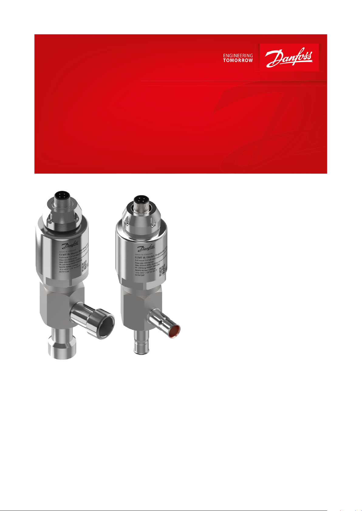
Electric regulating valves
Type CCMT 3L, 5L, 8L and 10L
One valve, 3 applications: HPV, GBV and EEV
The CCMT Light is an electrically operated valve
designed specically for operation in CO
systems.
The CCMT Light valve concept is designed to
fulll global refrigeration requirements.
The valve is capable of functioning either as an
expansion valve, as a pressure regulator for the
gascooler or as a gas bypass valve with backpressure regulation in transcritical or subcritical
applications.
2
Features:
• Designed for CO2 systems with maximum
working pressure of 140 bar / 2030 psig with
steel connections
• Designed for CO2 systems with maximum
working pressure of 130 bar / 1885 psig (120
bar / 1740 psig for UL approval) with Bi-metal
connection
• The CCMT Light is compatible with oil types
PAG and POE
• All-in-one function module ensures optimum
regulating accuracy, particularly at part load
• Patented cone and balance design
• The PTFE (TFM) seat provides excellent valve
tightness
• Steel connections with combined butt weld,
sleeve welding and brazing
• Unique bi-metal solder connections requiring
small amount of heat
• MOPD up to 90 bar / 1305 psi
• Integrated M12 male connector for simple
and exible connection to the motor driver
• Low weight and compact design
• Easy to service from the top by removing a
single function module insert
• For manual operation and service of the
CCMT an AST-g service driver is available
AI334224263620en-000201
Page 2
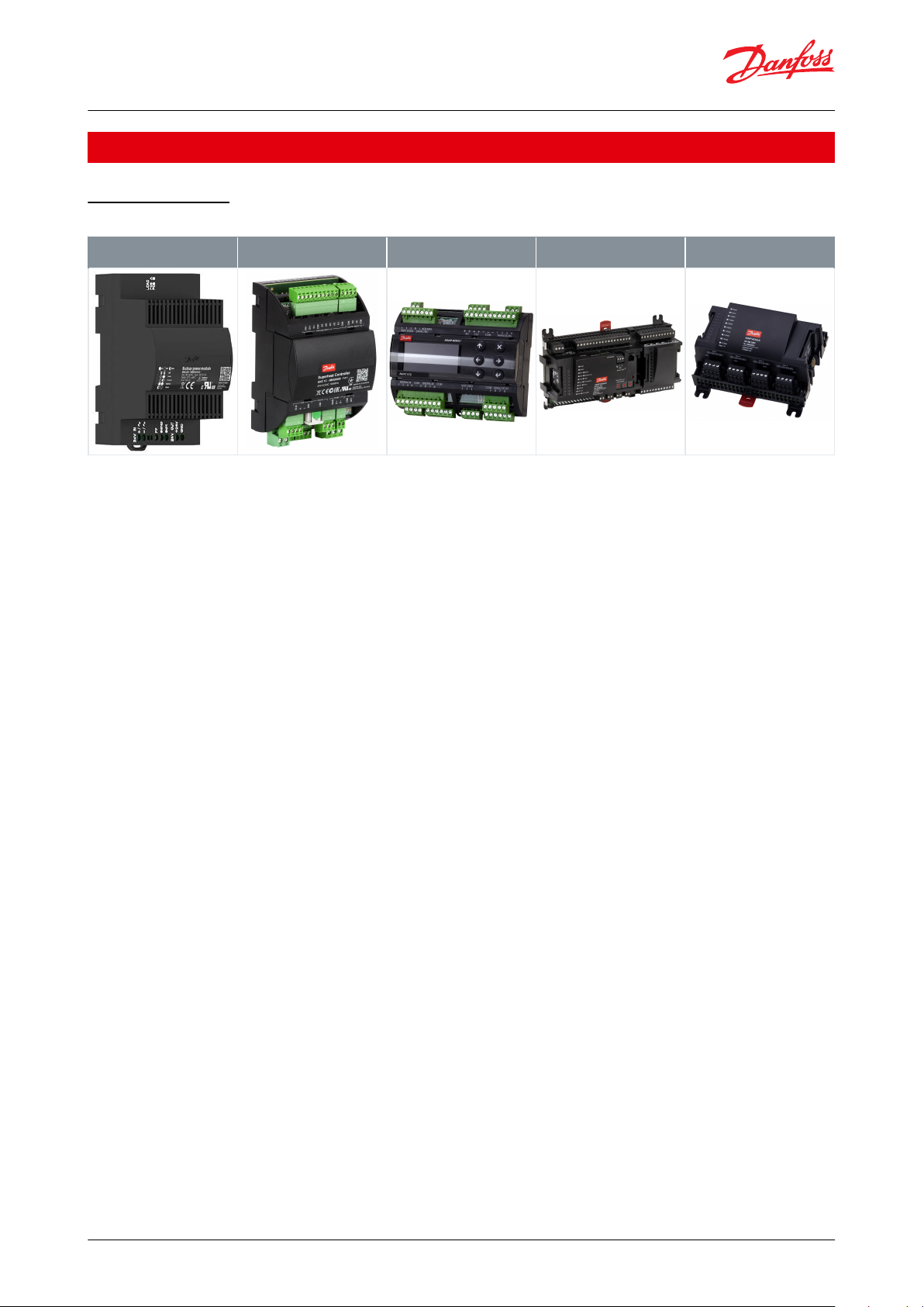
Superheat controller / driver,
type EKE 2U
Superheat controller / driver,
type EKE 1P
Electronic driver type AK-PC
572
Electronic driver type AK-PC
7XX
Electronic driver type AK-XM
208C
(1)
Electric regulating valves, Type CCMT 3L, 5L, 8L and 10L
Portfolio overview
Related products
Table 1: Portfolio overview
(1)
(1)
Please refer to CCMT Light installation guide for correct valve insulation recommendation related to usage of electronic driver type AK-
Please refer to CCMT Light installation guide for correct valve insulation recommendation related to usage of electronic driver type AKXM-208C.
XM-208C.
© Danfoss | Climate Solutions | 2021.03 AI334224263620en-000201 | 2
Page 3
AK-CC55
GC
AK-CC55
AK-PC 572 EKE 1P EKE 1 P EKE 2U
AKS 11
AKS 2050
AKS 11 AKS 2050
AKS 11
AKS 2050
AKVP
AKS 11
AKS 11
AKS 2050
FC 103
FC 103
AK-SM 800A
DGS
DGS
AKS 21
DGS
AKS 2050
AKS 2050
AKS 11
AKS 11
AKVP
CCMT L
CCMT L
HP High Pressure (120-140 bar)
HP Receiver Pressure (60-90 bar)
LP Suction Pressure MT (45-55 bar)
LP Suction Pressure LT (25-30 bar)
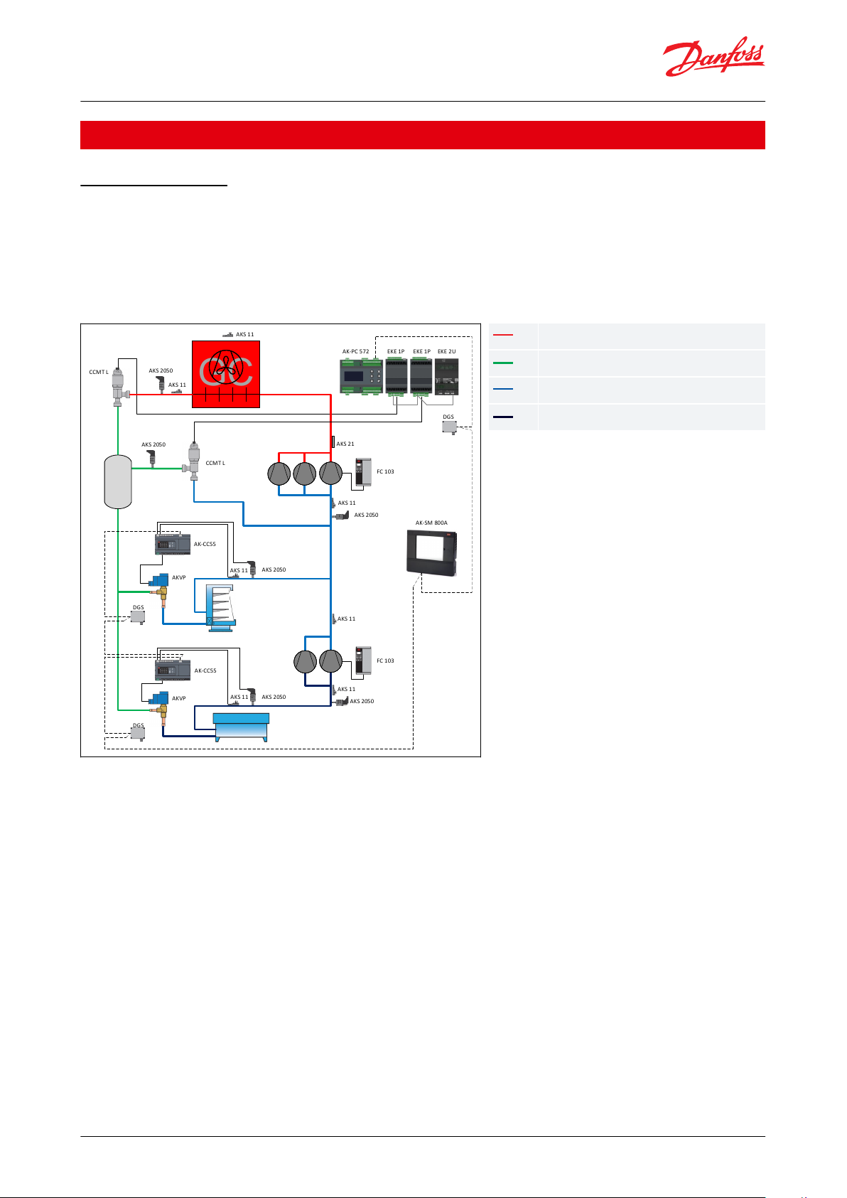
Electric regulating valves, Type CCMT 3L, 5L, 8L and 10L
Applications
Application 1 and 2
The CCMT Light valve is developed for transcritical CO2 applications. The CCMT valve can be used in systems with
ash gas bypass, parallel compression as well as in stand-alone applications.
The CCMT Light valve can be used in transcritical and subcritical conditions.
CCMT Light valves are typically used for liquid expansion and as ash gas bypass and high pressure regulation.
Figure 1: Application
Application 1 - High Pressure Valve (HPV)
The function of the high pressure valve is to control the high pressure in the system according to the reference from
the controller. The reference can be set to obtain the optimum COP, optimum capacity or any other factors. Pressure
optimization is performed by the CCMT valve, which is installed at the outlet of the gas cooler (see the gure above)
and a matching Danfoss controller. This design provides the possibility to optimize gas cooler pressure in all
situations and intermediate receiver pressure independently.
Please refer to the www.danfoss.com/CO2 for more information on CO2 systems.
Application 2 - Gas bypass Valve (GPV)
A gas bypass valve is typically used to regulate the intermediate pressure in a transcritical CO2 refrigeration system,
in order to keep the intermediate pressure low. By venting ash gas generated through a gas bypass valve to the
suction side of the compressor after the transcritcal expansion, the pressure can be kept at a safe level for all
components situated in the liquid lines of a transcritical CO2 system . The two phase mixture from the CCMT valve
has to be separated before gas enters the gas bypass. For use in the gas bypass applicaton the Danfoss AK
controllers are recommended.
© Danfoss | Climate Solutions | 2021.03 AI334224263620en-000201 | 3
Page 4
AK-CC55 EKE 1P
GC
AK-CC55 EKE 2U EKE 1P
AK-PC 782A AK-XM
AKS 11
AKS 2050
AKS 11 A KS 2050
AKS 11
AKS 2050
CCMT L
CCMT L
AKS 11
AKS 11
AKS 2050
FC 103
FC 103
AK-SM 800A
DGS
DGS
AKS 21
DGS
AKS 2050
AKS 2050
AKS 11
AKS 11
AKS 2050
CCMT
CCMT
HP High Pressure (120-140 bar)
HP Receiver Pressure (60-90 bar)
LP Suction Pressure MT (45-55 bar)
LP Suction Pressure LT (25-30 bar)
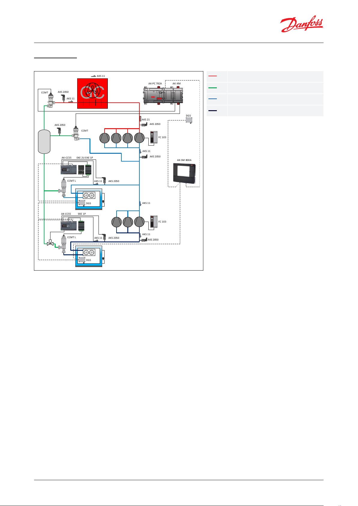
Electric regulating valves, Type CCMT 3L, 5L, 8L and 10L
Application 3
Figure 2: Application
Application 3- Expansion Valve (EEV)
A stepper expansion valve CCMT Light is typically used for injection in plate heat exchangers and as an expansion
valve for air CO2 evaporators.
© Danfoss | Climate Solutions | 2021.03 AI334224263620en-000201 | 4
Page 5

Parameter
CCMT 3L, 5L, 8L and 10L
Compatibility refrigerants
R744
Refrigerant oils
PAG and POE
MOPD
90 bar / 1305 psi
Max. working pressure (PS/MWP)
140 bar / 2030 psig with steel connections
130 bar / 1885 psig (120 bar / 1740 psig for UL approval) with Bi-metal connections
Refrigerant temperature range
-20 – 55 °C / 4 – 131 °F on valve inlet
-40 – 55 °C / 40 – 131 °F on valve outlet
Ambient temperature
- 40 – 50 °C / - 40 – 122 °F
Valve body material specication
Stainless steel
Built-in strainer / lter
No
Comply with P.E.D.
Fluid group I / Article 3, paragraph 3
Approval
cURus, EAC
Parameter
CCMT 3L, 5L, 8L and 10L
Stepper motor type
Bi-polar - permanent magnet
Motor enclosure
IP 67
Step mode
2 phase full step, microstepping (recommended)
Phase resistance
15 Ω ±10%
Phase inductance
16 mH
Phase current
Using chopper drive: 350 mA RMS +/- 10 %
Holding current
No voltage driver. Current controller: 20% of max. current
Duty cycle
20% duty cycle of period time 50 sec
Max. total power
Current drive: 1.8 W
Step rate
Chopper current drive: 100 steps/sec
Total full steps
210 steps
Full travel time
2.1 sec. ( at 100 steps sec. )
Reference position
Overdriving against full close position
Overdrive in close position
Max. 10% of total full steps
Overdrive in open position
Not Allowed
Electrical connection
Integrated M12 male connector
Compatible controllers
EKE 1P, EKE 2U, AK-PC 572, AK-PC 7xx, AK-XM 208C
(1)
Electric regulating valves, Type CCMT 3L, 5L, 8L and 10L
Product specication
Technical data
Table 2: Technical data
Electrical data
Table 3: Electrical data
(1)
(1)
Please refer to CCMT Light installation guide for correct valve insulation recommendation related to usage of electronic driver type AK-XM
Please refer to CCMT Light installation guide for correct valve insulation recommendation related to usage of electronic driver type AK-XM
208C
208C
WARNING:
At power failure the CCMT Light valve will remain in the actual opening position it has at the moment of power
failure, unless a safety device in the form of a battery backup is installed.
© Danfoss | Climate Solutions | 2021.03 AI334224263620en-000201 | 5
Page 6

1
6
3
4
2
5
7
13
11
10
14
8
12
9
1234567891011121314Connector socket
Top nut
Actuator cover
Lock ring for motor
Motor
Motor housing
O-ring
Valve housing with connectors
Actuator joint
Slider
Seal
Nozzle holder assembly
Nozzle
O-ring
CLOSING
STEP
Coil I (B)
Coil II (A)
OPENING
Red
Green
White
Black
1+-+-2+--+3-+-+4-++-1+-+-
Pin
Wire color
A1
WhiteA2BlackB1RedB2Green
B1
B2
A1
A2
1
3
2
4
Danfoss
34G177
Electric regulating valves, Type CCMT 3L, 5L, 8L and 10L
Design
Figure 3: Design
Stepper motor switch sequence
Table 4: Stepper motor switch sequence
Table 5: Danfoss cable connections
Figure 4: CCMT Light valve
If the controller driving the CCMT Light valve is from another manufacturer than Danfoss or a custom design, the
following points must be considered in order to overcome potential step loss.
To ensure total closing of the valve, and to compensate the lost steps after a dened number of changes in opening
degree. the controller should have a function to overdrive the valve in the closing direction. It is recommended to
overdrive ten percent of the full steps range at appropriate intervals.
© Danfoss | Climate Solutions | 2021.03 AI334224263620en-000201 | 6
Page 7

A
B
C
D
ABCDProduct type Code no.
Manufacturing date
Meters/Feets
Country
34G210.10
A2 black
A1 white
B1 red
B2 green
34G211.10
34G209.10
49 mm / 1.9 inch
Ø 6.3 mm / 1/4 inch
35 mm / 1.4 inch
2 + 0.089 meters / 6.6 + 0.3 feet
8 +0.3 meters / 26.2 +1 feet
Jacket
PVC - black
Cable outer sheath
Oil - resistant
Water proof rating
IP 67
Operating temperature range
-40 – +80 °C
Wire type
Twisted pair, cross section 20 AWG / 0.5 mm2
Cable outer diameter
7.0 mm
Minimum bending radius
10 x cable diameter
Cable combustibility / test
Flame retardant / VW-1 / CSA FT - 1
M12 standard
EN 61076-2-101
Reference standard
UL style 2464 and DIN VDE 0812
LVD directive
73/23/EEC and 93/68/EEC
Electric regulating valves, Type CCMT 3L, 5L, 8L and 10L
Accessories
M12 angle cable
M12 angle cable
M12 angle female connector is intended for use with the standard M12 male connector on CCMT Light valves. The
Danfoss cable is designed to oer high exibility and proper tensile strength. The Danfoss M12 cable also consists of
paired, twisted wires, which decreases mutual inuence between signals transmitted along the cable and reduces
inuence of external sources of interference. The cable thus provides a higher degree of protection against lost
steps compared to other cables.
Specication
Table 6: Specication
Identication
Figure 5: Identication
Connections and Dimensions
Figure 6: Connections
Figure 8: Dimensions
Figure 7: Connections
© Danfoss | Climate Solutions | 2021.03 AI334224263620en-000201 | 7
Page 8

Danfoss
DIM027H7250-00
1
4
6
m
m
[
5
.
7
i
n
]
40 mm
[1.6 in]
Ø
Ø
5
/
8
i
n
Ø5/8 in
4
5
m
m
[
1
.8
i
n
]
45 mm
[1.8 in]
4
1
m
m
M
I
N
[
1
.
6
i
n
]
1
4
6
m
m
[
5
.
7
i
n
]
Ø
7
/
8
i
n
40 mm
[1.6 in]
Ø
Ø7/8 in
4
5
m
m
[
1
.
8
i
n
]
45 mm
[1.8 in]
Danfoss
DIM027H7272-00
4
1
m
m
M
I
N
[
1
.
6
i
n
]
1
4
3
m
m
[
5
.
6
i
n
]
40 mm
[1.6 in]
Ø
4
2
m
m
[
1
.
6
i
n
]
42 mm
[1.7 in]
Ø
3
/
8
i
n
Ø3/8 in
Danfoss
DIM027H7275-00
4
1
m
m
M
I
N
[
1
.
6
i
n
]
Danfoss
DIM027H7247-00
1
4
1
m
m
[
5
.
6
i
n
]
40 mm
[1.6 in]
Ø
40 mm
[1.6 in]
4
0
m
m
[
1
.
6
i
n
]
Ø1/2 in
Ø
1
/
2
i
n
4
1
m
m
M
I
N
[
1
.
6
i
n
]
Electric regulating valves, Type CCMT 3L, 5L, 8L and 10L
Dimensions
Steel connections
Table 7: Steel connections
Bi-metal connections
Table 8: Bi-metal connections
© Danfoss | Climate Solutions | 2021.03 AI334224263620en-000201 | 8
Page 9

Type
Connections [in]
Flow rate
Packing format
Code no.
Bi-metal
Steel
kv [m3/h]
Cv [gpm]
Single pack
CCMT 3L
3/8 × 3/8-0.26
0.31027H7239
CCMT 3L
1/2 × 1/2-0.26
0.31027H7240
CCMT 3L
-
5/8 × 5/8
0.26
0.31027H7241
CCMT 3L
-
7/8 x 7/8
0.26
0.31027H7273
CCMT 5L
3/8 × 3/8-0.5
0.57
1
027H7242
CCMT 5L
1/2 × 1/2-0.5
0.57
1
027H7243
CCMT 5L
-
5/8 × 5/8
0.5
0.57
1
027H7245
CCMT 5L
-
7/8 x 7/8
0.5
0.57
1
027H7274
CCMT 8L
3/8 × 3/8-0.8
0.92
1
027H7275
CCMT 8L
1/2 × 1/2-0.8
0.92
1
027H7247
CCMT 8L
-
5/8 × 5/8
0.8
0.92
1
027H7250
CCMT 8L
-
7/8 x 7/8
0.8
0.92
1
027H7272
CCMT 10L
1/2 × 1/2-1.10
1.28
1
027H7277
CCMT 10L
-
5/8 × 5/8
1.10
1.28
1
027H7278
CCMT 10L
-
7/8 x 7/8
1.10
1.28
1
027H7279
Type
Description
Single pack
Code no.
Gasket
O-ring spare part kit for CCMT Light 3L, 5L, 8L and 10L
1
027H7276
Cable
Cable length (L)
Insulation
Packing format
Code no.
PVC - black
2 + 0.089 m / 6.6 + 0.3 ft
SR-PVC
Single pack
034G7073
8 + 0.3 m / 26.2 +1 ft
SR-PVC
Single pack
034G7074
Electric regulating valves, Type CCMT 3L, 5L, 8L and 10L
Ordering
Valve including actuator
Table 9: Valve including actuator
Spareparts
Table 10: Spareparts
Ordering
Table 11: Ordering
© Danfoss | Climate Solutions | 2021.03 AI334224263620en-000201 | 9
Page 10

File name
Document type
Document topic
Approval authority
19.10034.262
Marine - Safety Certicate
RMRS
RU Д-DK.АИ30.В.04995
EAC Declaration
PED
EAC
Electric regulating valves, Type CCMT 3L, 5L, 8L and 10L
Certicates, declarations, and approvals
The list contains all certicates, declarations, and approvals for this product type. Individual code number may have
some or all of these approvals, and certain local approvals may not appear on the list.
Some approvals may change over time. You can check the most current status at danfoss.com or contact your local
Danfoss representative if you have any questions.
Table 12: Certicates, declarations, and approvals
© Danfoss | Climate Solutions | 2021.03 AI334224263620en-000201 | 10
Page 11

Online support
Danfoss oers a wide range of support along with our products, including digital product information, software,
mobile apps, and expert guidance. See the possibilities below.
The Danfoss Product Store
The Danfoss Product Store is your one-stop shop for everything product related—no matter where
you are in the world or what area of the cooling industry you work in. Get quick access to essential
information like product specs, code numbers, technical documentation, certications, accessories,
and more.
Start browsing at store.danfoss.com.
Find technical documentation
Find the technical documentation you need to get your project up and running. Get direct access to
our ocial collection of data sheets, certicates and declarations, manuals and guides, 3D models
and drawings, case stories, brochures, and much more.
Start searching now at www.danfoss.com/en/service-and-support/documentation.
Danfoss Learning
Danfoss Learning is a free online learning platform. It features courses and materials specically
designed to help engineers, installers, service technicians, and wholesalers better understand the
products, applications, industry topics, and trends that will help you do your job better.
Create your Danfoss Learning account for free at www.danfoss.com/en/service-and-support/learning.
Get local information and support
Local Danfoss websites are the main sources for help and information about our company and
products. Find product availability, get the latest regional news, or connect with a nearby expert—all
in your own language.
Find your local Danfoss website here: www.danfoss.com/en/choose-region.
Danfoss can accept no responsibility for possible errors in catalogues, brochures and other printed material. Danfoss reserves the right to alter its
products without notice. This also applies to products already on order provided that such alterations can be made without subsequential
changes being necessary in specications already agreed. All trademarks in this material are property of the respective companies. Danfoss and
the Danfoss logotype are trademarks of Danfoss A/S. All rights reserved.
© Danfoss | Climate Solutions | 2021.03 AI334224263620en-000201 | 11
 Loading...