

Page 1
Installation guide
Fuse
Electronic operated valve
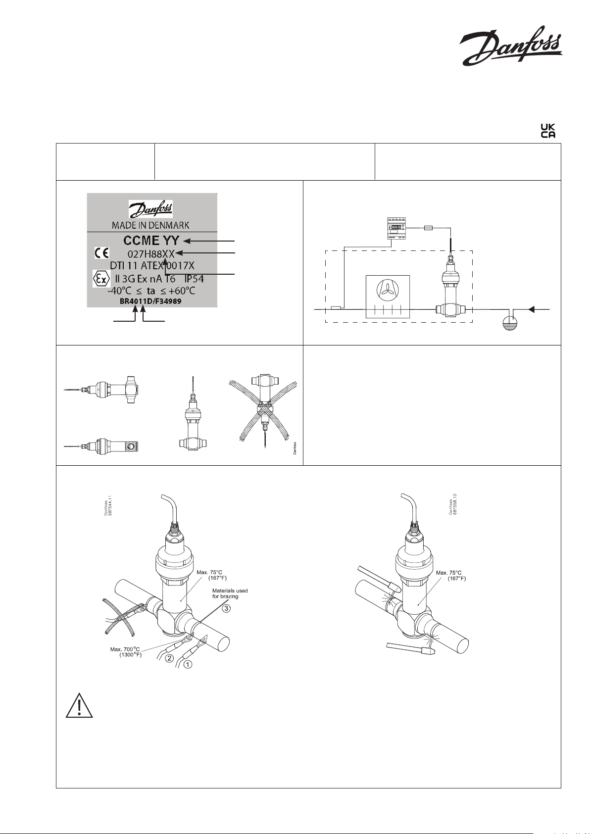
Type CCME
Refrigerant: R290
027R9843
Danfoss
34G146.10
Production
week
Mounting
Max. working pressure (PS/MWP): 90 bar (1305 psi)
Max. test pressure (PT): 130 bar (1885 psi)
Application
Danfoss
Valve type
Cable length:
1-9 meter
Valve type:
1=CCME10
2=CCME20
3=CCME30
4=CCME40
Production
year
34G144.10
The valve has to be 100% open when mounting - as delivered.
The valve must be supported with tube supporters either on
the valve itself or on the tubes connected to the valve. The valve
must not be exposed to any external influence like shock or
punches.
A filter with a maximum mesh of 100 μm is required on the inlet
line if the refrigerant contains particles above 100 μm.
Max. ambient temperature: 60 °C (140 °F)
Min. ambient temperature: -40 °C (-40 °F)
2 x 400 mA
NON-ZONE
ATEX ZONE 2
027R9843
Welding
Only allowed when there is no explosion danger.
Always ensure that there is no R290 present in the
pipes and in the surroundings.
To braze the parts they must be cleaned mechanically or
chemically, and after assembly add flux. Heat the parts by placing
the heat most to the part with the best heat transfer. In this case
the tube. When the parts are on brazing temperature add brazing
material.
© Danfoss A/S (AC-MCI/sw), 2021-01 AN027786414846en-000201
Materials used for brazing:
Flus: Metalli tenacity No. 5 Powder or Braze Tec special h paste.
Filler: Silver-Flo 55 (BS:AG 14/ DIN L-Ag55 Sn) or Silver-Flo 56
(AWS B Ag-7).
Filler metals containing Phosphor i.e. BS: CP 1/ DIN L-Ag 15P or
BS: CP 3/ DIN L-Ag P7 must not be used.
Info for UK customers only:Danfoss Ltd. Oxford Road, UB9 4LH Denham, UK
Page 2
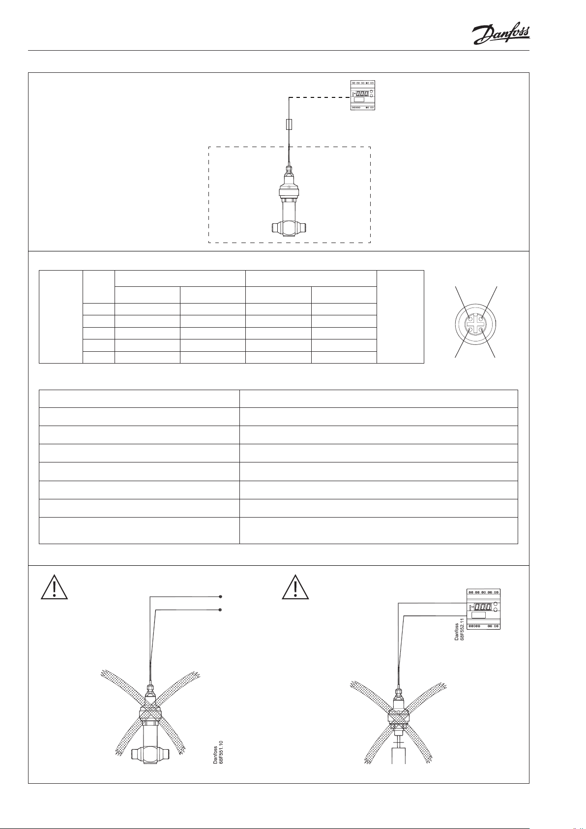
Connection
Stepper motor switch sequence
Fuse
2 x 400 mA
ZONE 2
NON-ZONE
Danfoss
34G145.10
STEP
Connection A Connection B Connection C Connection D
1 + - + -
Coil I Coil II
Closing
2 + - - +
OPENING
3 - + - +
4 - + + 1 + - + -
Electrical specifications
Parameter CCME
Stepper motor type / Step mode Bi-polar - permanent magnet / 2 phase full step
Phase resistance 52 Ω ±10 %
Nominal voltage (Constant voltage drive) 12 V dc -4% – 15%, 150 steps/sec.
Phase current (Using chopper drive) 100 mA RMS -4% – 15%,
Max. total power Voltage / current drive: 5.5 / 1.3 W (UL: NEC class 2)
Electrical connection 4 wire 0.5 mm2 (0.02 in2), 0.3 m (1 ft) long cable
Fuses required on wires from connection A and C
(Refer to the drawing above)
For further technical data please refer to the Data sheet
400 mA (each fuse) / IEC 60127
A B
Danfoss
34G147.10
DC
Warning! Warning!
Do not apply power
directly to valve.
Do not apply power to
unassembled valve.
2 | AN027786414846en-000201 © Danfoss A/S (AC-MCI/sw), 2021-01
Page 3

ENGLISH
Commission
Safety
Installation
General remarks
For safety reasons, the installation must
take place under the supervision of an
authorised person taking account of local
safety instructions, for flammable fluids,
and advisories, e.g. EN 60079-14.
The handling of valves and their controls
must be done only by staff trained in all
technical aspects of their operation.
Before installation the pipes must be
depressurised and purged (empty of its
fluid) in order to avoid any danger to the
operator.
In ATEX zone, check that the pipes are
connected to the earth (grounded).. Do
not use insulating pipes (PVC…)
- Check that the valves are suitable for
the actual refrigerant.
- Check that the valves are suitable for|
the actual zone.
Before putting valve into operation, check
that:
- The working conditions are compatible
with the details given on the
identification label.
- All electrical connections have been
properly made.
- Installation is tight after the assembly.
Maintenance
- Maintenance and repair work must be
carried out by qualified personnel (ref.
EN 60079-19)
- The pipe must be depressurized and
purged (emptied of its fluid) in order
to avoid any danger to the operator. If
the installation has carried fluids which
are dangerous in themselves if in
contact with the outside atmosphere
(inflammable, corrosive, toxic,
explosive..)
- All operations must be performed
using suitable protective (clothing,
gloves, mask…).
- Where a control uses an external energy
source, it is essential to isolate this
source before any operation.
As well as the indications given in the
preceding paragraphs of this notice, it is
imperative that the following instructions
be followed:
- This notice must be available on site
where valves are installed.
- Personnel carrying out any intervention
on the valve must be qualified for the
task. In ATEX zone, the personnel must
be educated in the risks of explosion,
and should have received specific ATEX
training (ref. EN 60079-14).
- In case the forwarded media would
be an explosive atmosphere (deliberate
internal explosive) or should it cause an
explosive atmosphere in case of external
leakage, the user must check the
tightness of the installation after
assembling, after a faulty operation or
on a periodic basis undernormal
conditions
- It is the responsibility of the user to
check after the installation of the
valve that there is no leakage. Especially
in case of deliberate internal explosive
atmospheres.
- Internal rules and legislation current
in the country concerned with respect to
health and safety at work must be
applied and respected.
- The valve and its control must not
undergo any modification without prior
approval from our advisory service.
Danfoss is not responsible for any damage
which may be caused by the use of parts,
accessories or controls which are not
original Danfoss parts
- Hot or cold parts of the valve which
present a danger to the operator must
be protected.
- In ATEX zone, the valve and its control
must be cleaned regularly to avoid the
accumulation of dust.
- In ATEX zone do not mount valves at
open ends of lines.
© Danfoss A/S (AC-MCI/sw), 2021-01 AN027786414846en-000201 | 3
 Loading...