

Page 1
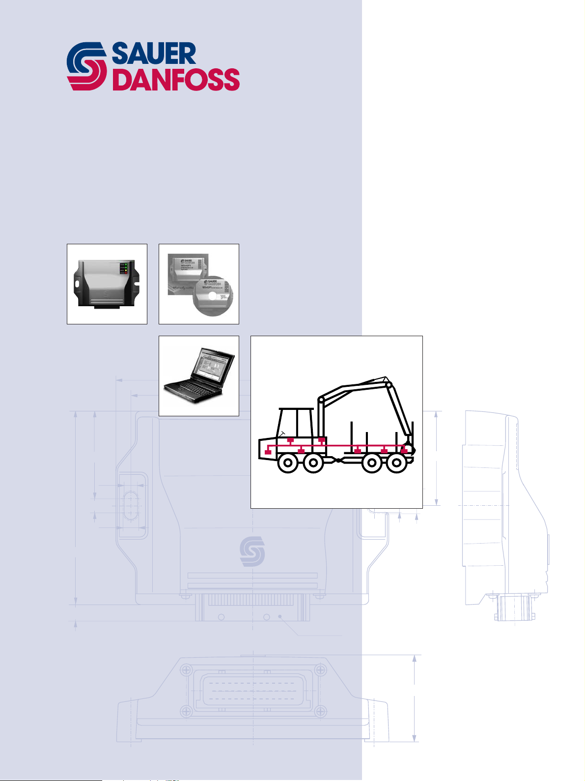
CAN
Controller
Area
Network
Technical
Information
123,5
10,5
55,75
174
155
POWER
SYSTEM
MODE
STATUS
8,5
9
10
AMP Stecker
AMP Connector
60,25
8,5
10
1
15
29
14
28
42
55
Page 2

CAN Controller Area Network
Technical Information
Overview
HISTORY
WHAT IS CAN
Forced by the increasing number of distributed control systems in cars and the
increasing wiring costs of electronics, the availability of a powerful and reliable data
communication system for the exchange of information between the different control
units was becoming urgent.
This was the starting point for BOSCH, a main provider of electronic car equipment to
develop the CAN protocol and standardize it as an international standard in ISO 11898.
1989 the fi rst protocol controller chip was provided by INTEL.
CAN is a serial bus system which is especially suited for connecting devices within a
system or sub-system. These devices (nodes) can be intelligent devices as well as sensors
and actuators.
CAN is a serial bus system with multi-master capabilities, that means that all CAN
nodes are able to transmit data and several CAN nodes can request access to the bus
simultaneously. A transmitter sends a message to all CAN nodes (broadcasting).
A CAN message can transmit from 0 up to 8 bytes of user information. Each CAN Message
starts with a so called identifi er followed by the data bytes. This identifi er can be 11
Bit or 29 Bit wide. If the identifi er is 11 bit wide, than it is a message in „standard
format“ (CAN specifi cation 2.0 Part A). Otherwise it is a message in the „extended format“
(CAN specifi cation 2.0 Part B). Please be aware that not all CAN controller supports the
extended format.
Each node decides on the basis of the identifi er received whether it should process the
message or not. The identifi er also determines the priority that the message have in
competition for bus access.
One of the outstanding features of the CAN bus is its high transmission reliability. The
CAN protocol controller detects a stations error and evaluates it statistically in order to
take appropriate actions. These may extend to disconnecting the CAN node producing
the errors.
BENEFITS
2
The use of a CAN system increases the fl exibility of a system. One of the most obvious
benefi ts is reduced wiring. A single two-wire bus is all that is needed to connect several
CAN devices. This reduces costs, simplifi es mechanical design, and makes it easier to
insert additional devices into a system.
The key benefi t of CAN, like any network, is that it makes it possible to share resources
and information between devices. This means that one sensor can easily be shared
between two or more controllers, or two controllers may share information about their
respective subsystems. Instead of using point to point communications, any device on a
CAN network can communicate with any other.
An additional benefi t of this is that system diagnostics can be centralized and simplifi ed.
As a single device can access all of the devices on the CAN, it is possible to centralize
diagnostic tools to a single access point.
© 2001, Sauer-Danfoss
Sauer-Danfoss can accept no responsibility for possible errors in catalogues, brochures and other printed material. Sauer -Danfoss reserves the
right to alter its products without prior notice. This also applies to products already ordered provided that such alterations can be made without
subsequent changes being necessary in specifi cations already agreed. All trademarks in this material are properties of the respective companies.
Sauer-Danfoss and the Sauer-Danfoss logotype are trademarks of the Sauer-Danfoss Group. All rights reserved.
BLN-96-9916-E • Rev. A • 08/2001
Page 3

CAN Controller Area Network
Technical Information
Overview
BUS TOPOLOGY
According to ISO 11898 the CAN-Bus is realized by a cable with two lines. The bus cable is
terminated at both
ends by termination resistors (see fi gure 1).
Note: The stub cable, which is the cable from the bus cable to a node, is an unterminated
cable and should be as short as possible.
Figure 1: CAN-Bus realization
CAN Bus
Terminal
Node 1
Microcontroller
CAN Controller
CAN Transceiver
CAN L
CAN H
CAN H
CAN L
Node X
Microcontroller
CAN Controller
CAN Transceiver
CAN L
CAN H
CAN Bus
Terminal
S01821a
BUS CABLES AND TERMINATION RESISTORS
DATA EXCHANGE
The table below shows some standard values for CAN-networks according to ISO 11898
with less than 64 nodes and can be used as a kind of guideline. In addition, the cable
should have following AC parameters:
- A 120 Ω impedance and a 5 ns/m specifi c line delay.
Bus cable
Bus length Length related Cross section Termination Baud rate
[m] resistance [mΩ/m] [mm²] resistance [Ω] [Kbit/s]
0...40 70 0.25...0.34 120 1000 at 40 m
40...300 < 60 0.34...0.60 150 ... 300 > 500 at 100 m
300...600 < 40 0.50...0.60 150 ... 300 > 100 at 500 m
600...1000 < 26 0.75...0.80 150 ... 300 > 50 at 1 km
When data is transmitted through a CAN Network, no nodes are addressed, but instead,
the content of the message (e.g. engine rpm or vehicle speed) is designated by an
identifi er that is unique throughout the network.
If the Microcontroller of a given node wishes to send a message to one or more nodes,
it passes the data to be transmitted and their identifi ers to the assigned CAN controller
(“Prepare”). This is all the Microcontroller has to do: To initiate the data exchange. The
message is constructed and transmitted by the CAN controller itself.
BLN-96-9916-E • Rev. A • 08/2001
3
Page 4

CAN Controller Area Network
Technical Information
Overview
DATA EXCHANGE
(continued)
HIGHER LEVEL PROTOCOLS
As soon as the CAN controller receives bus access (“Transmit”) all other nodes on the CAN
network become receivers of this message (“Receive“). Each node in the CAN network,
having received the message correctly, performs an acceptance test to determine
whether the received data is relevant for that station (“Check”). If the data is of interest
for the node it is processed (“Process”), otherwise ignored.
Figure 2: CAN network
Node 1
Process
Check
Receive
CAN Bus
Node 2
Check
Receive
Node 3
Prepare
Transmit
Node 4
Process
Check
Receive
S01822a
All the above mentioned specifi cations describes how data is physically transmitted
through the CAN network but not what kind of data. This means that the CAN controller
does not care with which identifi er the engine RPM is transmitted.
This is the task of the system designer. He has to design what data is transmitted
through the bus. Due to that application specifi c data exchange solutions have been
implemented.
These so called „proprietary“ protocols are mainly not compatible to each other because
they are optimized for a specifi c application.
In this case optimized means:
• Bandwidth usage of the bus
• Memory allocation in the control unit
• Reaction time
For an open system approach several higher layer protocols have been envolved. Most
popular protocols of that are:
• SAE J1939
• CANOpen
• CANKingdom
REFERENCES • Robert Bosch GmbH:
CAN specifi cation 2.0 Part A+B (1991)
• CiA DS-102:
CAN physical layer for industrial applications (1994)
• Konrad Etschberger (Hrsg.):
Controller-Area-Network; Grundlagen, Protokolle, Bausteine, Anwendungen (2000)
4
BLN-96-9916-E • Rev. A • 08/2001
Page 5

CAN Controller Area Network
Technical Information
Notes
BLN-96-9916-E • Rev. A • 08/2001
5
Page 6

OUR PRODUCTS
Hydrostatic transmissions
Hydraulic power steering
Sauer-Danfoss Hydraulic Power Systems
– Market Leaders Worldwide
Sauer-Danfoss is a comprehensive supplier providing complete
systems to the global mobile market.
Electric power steering
Closed and open circuit axial piston
pumps and motors
Gear pumps and motors
Bent axis motors
Radial piston motors
Orbital motors
Transit mixer drives
Planetary compact gears
Proportional valves
Directional spool valves
Cartridge valves
Hydraulic integrated circuits
Hydrostatic transaxles
Integrated systems
Sauer-Danfoss serves markets such as agriculture, construction, road
building, material handling, municipal, forestry, turf care, and many
others.
We offer our customers optimum solutions for their needs and
develop new products and systems in close cooperation and
partner ship with them.
Sauer-Danfoss specializes in integrating a full range of system
components to provide vehicle designers with the most advanced
total system design.
Sauer-Danfoss provides comprehensive worldwide service for its
products through an extensive network of Authorized Service
Centers strategically located in all parts of the world.
Sauer-Danfoss (US) Company
2800 East 13th Street
Ames, IA 50010, USA
Phone: +1 515 239-6000, Fax: +1 515 239-6618
Fan drive systems
Electrohydraulic controls
Digital electronics and software
Battery powered inverter
Sensors
BLN-96-9916-E • Rev. A • 08/2001
Sauer-Danfoss (Neumünster) GmbH & Co. OHG
Postfach 2460, D-24531 Neumünster
Krokamp 35, D-24539 Neumünster, Germany
Phone: +49 4321 871-0, Fax: +49 4321 871-284
Sauer-Danfoss (Nordborg) A/S
DK-6430 Nordborg, Denmark
Phone: +45 7488-4444, Fax: +45 7488-4400
Sauer-Danfoss (US) Company
3500 Annapolis Lane North
Minneapolis, MN 55447, USA
Phone: +1 763 509-2084, Fax: +1 763 559-0108
www.sauer-danfoss.com
 Loading...