

Page 1
Cables and Followers
BLN-95-8975-4 Issued: May 1996
DESCRIPTION
The Cables and Followers described in this instruction
literature are designed for use with Danfoss controllers
and sensors such as the R7232A Proportional Indicating
Controller, SB104A Microsyn Rotary Position Sensor
W895A Proportional Grade/Steering Controller,
MCW100A,B Time Proportional Rotary Position Controller,
MCW100C,E Time Proportional Rotary Position Controller
and MCW102B Proportional Rotary Position Controller.
Followers are used to run along a stringline for grade or
steering applications or along a hard reference surface to
match the existing grade. Cables are provided to make
electrical connections between components of the control
system and come in a variety of lengths and connector types.
ORDERING INFORMATION
SPECIFY
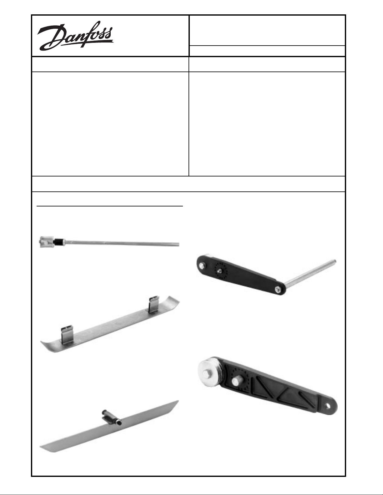
1. KG07002 16" Steering Follower with nylon grid adapter
FEATURES
• Number of followers meets almost any grade application
• Right-angle followers give way when they strike a fixed
object, preventing follower damage. See Figure 3.
• Environmentally sealed cables and connectors resist
moisture.
• No tools required to fasten—only turning one thumbscrew is necessary
• Cables simplify installation of control components, making wiring easy
4. KG04003 Grade Follower 8" Tube
with nylon arm (pictured)
KG04004 Grade Follower 12" Tube
with nylon arm
2. KG02001 Ski Runner
3. KG06001 Skate Assembly
5. K09274 Grid Arm - nylon
© Danfoss, 2013-09 BLN-95-8975_4 1
.
.
Page 2
ORDERING INFORMATION
SPARE PARTS
(continued)
PART NO. DESCRIPTION
K04760 Thumbscrew/O-ring Bag Assembly for KG04003, KG04004
K04420 Contact tube (8")
K04482 Contact tube (12")
K04331 Thumbscrew for KG07002
TECHNICAL DATA
TORQUE REQUIRED TO FLEX BREAKAWAY JOINT
170 ±30 inch-ounces (steering/rotary position followers)
110 ±30 inch-ounces (right-angle rotary position fol-
lower)
DIMENSIONS
See Dimension 1-4 Diagrams.
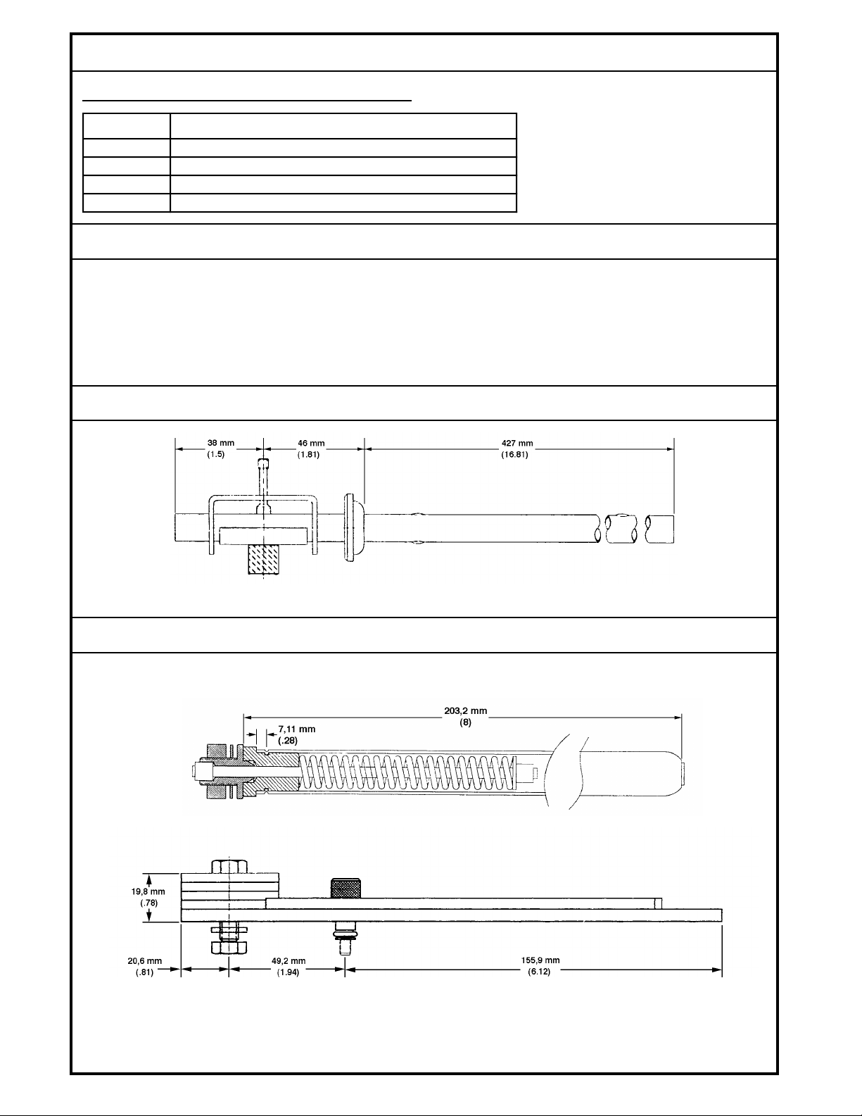
DIMENSION 1 DIAGRAM
Dimensions of the Steering/Grade Follower in Millimeters (Inches). Part Number KG07002.
DIMENSION 2 DIAGRAM
1975
Grid Assembly.
Arm Assembly.
Dimensions of the Right Angle Grade Follower in Millimeters (Inches). Part Number KG04004.
2
1976
Page 3
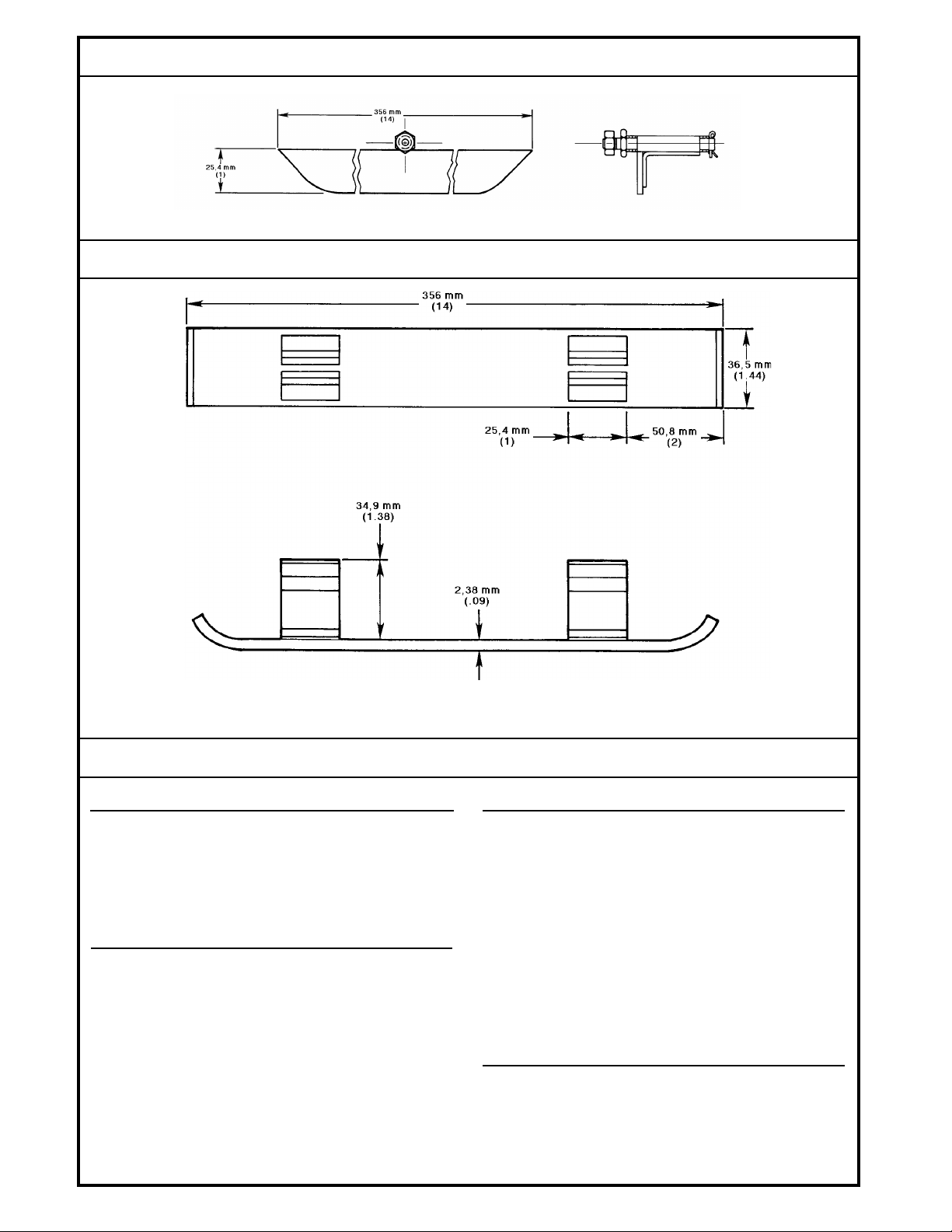
DIMENSION 3 DIAGRAM
Dimensions of the Skate Assembly in Millimeters (Inches). Part Number KG06001.
DIMENSION 4 DIAGRAM
1187
Dimensions of the Ski Runner in Millimeters (Inches). Part Number KG02001.
INSTALLATION
STEERING FOLLOWERS
The Steering Wand is pictured in the Ordering Information
KG07002 photograph. The device attaches to either the left
or right hub of a steering controller, such as the SB104A or
W895A. When the system is steering on course, the shaft of
the Wand will be vertical.
RIGHT ANGLE GRADE FOLLOWERS
The grade followers shown in the Ordering Information
KG04003 and KG04004 photographs are used to follow a
grade stringline. The two followers are identical, except that
one has a longer contact tube. They may be used on either
side of the controller in any of four orientations: 45 degrees
downtrailing, 45 degrees down preceding, level trailing or
level preceding.
940B
SKATE AND SKI ASSEMBLIES
The Skate assembly, shown in Ordering Information
KG06001 photograph, attaches to the Grid Arm by slipping
the Skate’s pin through the retaining hole in the Grid Arm (in
place of the tube) and fastening it with the retaining pin.
The Skate assembly always trails the controller at 45
degrees, following over a hard, pre-formed surface.
The Ski runner, shown in Ordering Information KG02001
photograph, snaps into the Skate assembly to follow a rigid
surface. As with the Ski assembly alone, it always trails the
controller at 45 degrees down.
CABLES
Cables and connectors are sealed against moisture when
mated with Danfoss devices: the connector insert
faces are rubber, so that a face-to-face moisture seal is
made. The cable termination into the connector is likewise
moisture sealed.
3
Page 4

INSTALLATION - CABLES
(continued)
Many different cables are available, depending on the specific application. Leads are wired to terminals in sequence
starting with A. Those most frequently used are:
1. KW01007, KW01009 and KW01011 Sensor Cables
(One-foot, two-foot and four-foot cables that extend to
five, ten and twenty feet, respectively. Mate with a Bendixtype six-pin MS3102A-14S-6P (K04183) connector on
both ends.)
2. KW01013, KW01014 Power Valve Cables (Two-foot
coiled cables that extend to ten feet. Have ten-pin straight
connector on one end and straight connector (KW01014)
or right-angle connectors (KW01013) on the other. Mate
with a Bendix Part Number MS3102A-18-1P (K03989)
connector.
3. KW01001 Cable (Two-foot coiled cable that extends to
five feet. Has five-pin straight connector on one end and
spade lugs on the other marked A, B, C, and D. Mates with
an MS3102A-16S-8P (K03992) connector on one end
and a terminal strip.)
4. KW01018, KW01019 Extension Cables (Eight-foot and
twenty-foot straight cables, respectively. Have six-pin
connectors on either end. Mate with Bendix Part Number
MS3102A-14S-6P (K04183) connectors at the two ends.)
Cables with screw-type connectors are keyed so that the
connectors join in only one way.
When installing panel-mounted amplifiers such as the
R7232A, allow room for cable connectors within the panel.
Four inches is the minimum space needed, as shown in
Figure 1. If cables must be removed or connected after the
amplifier is installed, allow a minimum of five inches.
941A
Figure1. Mounting Dimensions in Millimeters
(Inches) of the R7232A.
INSTALLATION - LOCATION
Attach the appropriate follower to the hub. Note the guide
hole location and direction of travel. Guide holes in the
mounting bracket for the steering follower, Part number
KG07002, are located as shown (see Figure 2). The follower
may be attached to either hub. The right angle follower, Part
number KG04003, is used for grade applications.
BREAKAWAY JOINT
STEERING
LEFT HUB
GRADE
RIGHT
1
HUB
THE RIGHT HUB IS DEFINED AS THE ONE WITH
1
THE SPRING BIAS ADJUSTMENT THUMBSCREW
LEFT
HUB
STEERING
RIGHT HUB
Figure 2.
1
952B
1977
Figure 3. Breakaway Knee Action of Right Angle
Grade Follower.
4
Page 5

INSTALLATION - LOCATION
(continued)
The right angle follower KG04003 is shown attached to the
MCW100C,E hub horizontally (See Figure 4.) The flat on the
hub should be parallel to the grade reference.
Figure 4.
1825
The follower may be attached at a 45° angle downward.
(See Figure 5.)
The follower may be attached at a 45° angle upward. (See
Figure 6.) and the follower should be positioned toward the
operator panel.
1827
Figure 6.
The straight tubular follower KG07002 is used for steering
control (see Figure 7).
Figure 5.
1826
Figure 7.
1828
5
Page 6

INSTALLATION - LOCATION
A skate assembly (Part number KG06001) and ski assembly
(Part number KG02001) may be used with the right angle
follower (Part number KG04003) when a firm reference
surface is used, as shown attached to the W895A. (See
Figures 8, 9 and 10.)
RIGHT
HUB
TRAVEL
GRID ARM
SKI
SKATE
Figure 8.
TRAVEL
1950 1970
Figure 9.
Figure 10.
951A
6
Page 7

CUSTOMER SERVICE
NORTH AMERICA
ORDER FROM
Danfoss (US) Company
Customer Service Department
3500 Annapolis Lane North
Minneapolis, Minnesota 55447
Phone: (763) 509-2084
Fax: (763) 559-0108
DEVICE REPAIR
For devices in need of repair, include a description of the
problem, a copy of the purchase order and your name,
address and telephone number.
RETURN TO
Danfoss (US) COMPANY
Return Goods Department
3500 Annapolis Lane North
Minneapolis, Minnesota 55447
EUROPE
ORDER FROM
Danfoss (Neumünster) GmbH & Co.
Order Entry Department
Krokamp 35
Postfach 2460
D-24531 Neumünster
Germany
Phone: 49-4321-8710
Fax: 49-4321-871-184
7
 Loading...