

Page 1
Data sheet
Micro Plate Heat Exchanger
Power savings
C55-EU Evaporator
30%
Lower hold-up volume
Signicant reduction
in refrigerant and
smaller CO2 footprint,
compared with a
traditional BPHE
ra.danfoss.com
Page 2
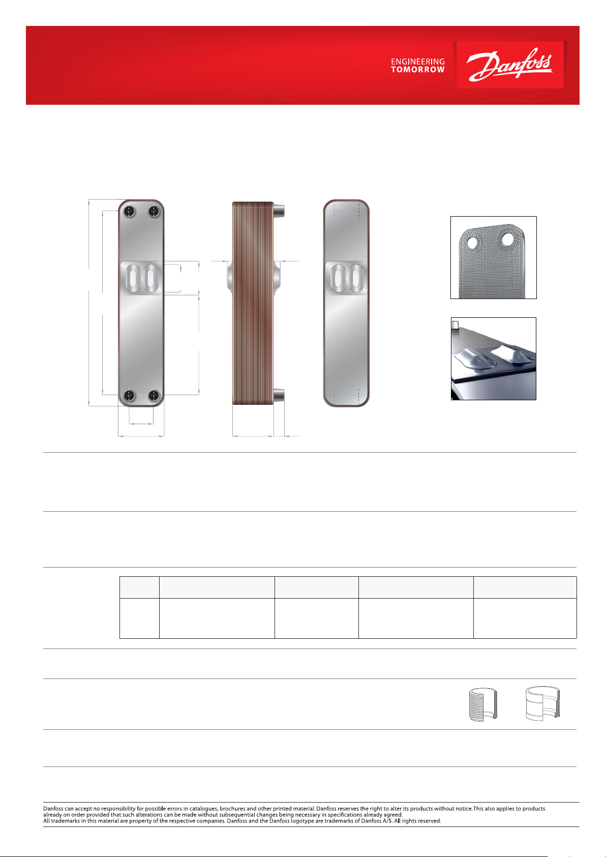
C55-EU Evaporator
Micro Plate Heat Exchanger
Introduction
525
20.7”
466
18. 3”
Q4 Q1
Q3 Q2
109/4.3”
50/2.0”
43.3
1.7”
80
3.1”
253.5
10.0 ”
9
0.4”
9.5 + 1.74n /
0.37” + 0.07n
14
0.6”
45/1. 8”
29/1.1”
25/1. 0”
20/0.8”
H1 H4
Unique channel plate pattern
H2 H3
Unique refrigerant distribution
The C55-EU is mainly developed as evaporator for high eciency chillers using R407C/R404A/R134a or other low pressure refrigerants and
covering cooling capacities 10 to 65 kW (3-18 Rt), but it can also be used as economizer. Equipped with Power Bulges - an innovative distri-
bution system - the evaporators enables a perfect refrigerant distribution, thereby improving heat transfer, minimizing pressure drop and
being less sensitive to inlet connection and pipe size. It is based on the well proven MPHE technology, meaning minimal refrigerant charge
and less weight for both environmental and nancial savings.
Key features
Technical data
n = number of plates
max. No. Of plates: 150
Standard
materials
Connections
Third-party
approvals
Accessories
– stud bolts
• Low hold up volume refrigerant side; less refrigerant charge in the system
• Lower weight; less sensitive to raw material price uctuations and reduced CO2 footprint
• Unique refrigerant distribution system, Power Bulges;
• Less sensitivity to inlet connection and pipe size
• Low pressure drop on refrigerant side
Model:
C55-EU
Min/Max. working
temperature
-196 °C / 200°C
-320 °F / 390 °F
Max. working
pressure
30 bar
435 psi
Hold-up volume
Q1-Q2 / Q3- Q4
(l): 0.082xn/2 / 0.07x(n-2)/2
(ft3): 0.003xn/2 / 0.002x (n-2)/2
Weight
2. 57kg+ 0.135xn
5.67lb+0.30xn
Cover plates: AISI 304L Plates: AISI 316L
Connections: AISI 304L Brazing ller: Pure copper
Primary side/ Refrigerant side: Secondary side/ Water side/Q1/Q2/H1/H2:
Inlet/Q3/H3: Soldering3/8”, 1/2”, 5/8”, 7/8” External thread 1”, 1 1/4”
Outlet/Q4/H4: Soldering 5/8”, 7/8”, 1”, 1 1/8”, 1 3/8” Soldering 1”, 1-1/8”, 1 3/8”
For other connections, please contact your Danfoss representative.
Europe: Pressure Equipment Directive (PED).
America: Underwriters Laboratory Inc (UL).
Others: For details of other existing approvals or to discuss how we can meet your local needs, please contact your Danfoss representative.
Stud bolts on front and/or back cover plates for mounting support are available upon request. Contact your Danfoss sales representative for
further information.
DKQB.PD.310.I2.02 © Copyright Danfoss RC-MDP | sw | 08 2014
 Loading...