

Page 1
Technical Information
BDU Series
Hydrostatic Transmissions
www.danfoss.com
Page 2
Technical Information
BDU Series Hydrostatic Transmissions
Revision history Table of revisions
Date Changed Rev
November 2021 Removed contents of BDP, and aligned revision number along with DAM Hub. 0207
November 2020 Minor update in Hydraulic Fluid, and changed document number from 'BC00000025' and
'520L0935' to 'BC152886484098'
December 2018 Fixed Model Code "H" 0103
May 2017 Fixed typo 0102
June 2016 Convertd to DITA-CMS 0101
Mar 2010 Correction - Drawing AC
Jan 2009 Correction - Text AB
Jan 2006 First edition AA
0104
2 | © Danfoss | November 2021 BC152886484098en-000207
Page 3

Technical Information
BDU Series Hydrostatic Transmissions
Contents
General Description
BDU Series Family.............................................................................................................................................................................5
Features and Benefits......................................................................................................................................................................5
Design...................................................................................................................................................................................................6
BDU-06/10S........................................................................................................................................................................................ 8
Pictorial Diagram.........................................................................................................................................................................8
System Schematic.......................................................................................................................................................................8
BDU-10L/21L/21H.............................................................................................................................................................................9
Pictorial Diagram.........................................................................................................................................................................9
System Schematic: BDU-21L................................................................................................................................................... 9
System Schematic: BDU-21H................................................................................................................................................10
Technical Specifications
Features and Options................................................................................................................................................................... 11
Operating Parameters..................................................................................................................................................................12
Fluid Specifications....................................................................................................................................................................... 12
Efficiency........................................................................................................................................................................................... 13
BDU-06S....................................................................................................................................................................................... 13
BDU-10S....................................................................................................................................................................................... 13
BDU-10L....................................................................................................................................................................................... 13
BDU-21L/21H..............................................................................................................................................................................14
Operating Parameters
Overview........................................................................................................................................................................................... 15
Input Speed......................................................................................................................................................................................15
System Pressure..............................................................................................................................................................................15
Charge Pressure..............................................................................................................................................................................15
Charge Inlet Pressure....................................................................................................................................................................15
Case Pressure...................................................................................................................................................................................16
Hydraulic Fluids.............................................................................................................................................................................. 16
Temperature and Viscosity.........................................................................................................................................................16
System Design Parameters
Fluid and Filtration........................................................................................................................................................................ 17
Reservoir............................................................................................................................................................................................17
Control Shaft Force........................................................................................................................................................................17
Independent Braking System....................................................................................................................................................17
Features and Options
Shaft Load.........................................................................................................................................................................................18
Shaft Options...................................................................................................................................................................................18
Shaft Options : BDU-06S/10S/10L............................................................................................................................................ 19
Shaft Options : BDU-21L/21H.................................................................................................................................................... 20
Bypass Valve.....................................................................................................................................................................................21
High Pressure Relief Valve (hprv) and Charge Check (Overpressure Protection)...................................................21
Charge Check Valve with Orifice.............................................................................................................................................. 23
Charge Check with Orifice.......................................................................................................................................................... 24
Optional Integrated Reservoir...................................................................................................................................................25
Filter....................................................................................................................................................................................................25
Fan.......................................................................................................................................................................................................26
Component Selection
Maximum System Pressure........................................................................................................................................................ 27
Input Power......................................................................................................................................................................................28
Unit Life..............................................................................................................................................................................................29
Model Code
BDU : Model Code (A - B - C - D - E)..........................................................................................................................................31
BDU : Model Code (F - G).............................................................................................................................................................32
BDU : Model Code (H - J - K)........................................................................................................................................................33
Recommended Installation and Maintenance
©
Danfoss | November 2021 BC152886484098en-000207 | 3
Page 4

Technical Information
BDU Series Hydrostatic Transmissions
Contents
Housing Installation......................................................................................................................................................................34
Shaft Installation.............................................................................................................................................................................34
Start Up Procedure........................................................................................................................................................................ 34
Operation..........................................................................................................................................................................................34
Maintenance....................................................................................................................................................................................34
Installation Drawings
BDU-06S : Ports and Dimensions..............................................................................................................................................35
BDU-06S : Control Arm Location.............................................................................................................................................. 36
BDU-06S : Motor Shaft..................................................................................................................................................................36
BDU-10S/10L : Ports and Dimensions.....................................................................................................................................37
BDU-10S/10L : Control Arm Location..................................................................................................................................... 38
BDU-10S/10L : Motor Shaft.........................................................................................................................................................39
BDU-10S : Shaft Configuration..................................................................................................................................................40
BDU-10L : Shaft Configuration and Charge Pumps Displacement..............................................................................41
BDU-21L/21H : Ports and Dimensions....................................................................................................................................42
BDU-21L/21H : Control Arm Location.....................................................................................................................................43
BDU-21L/21H : Motor Shaft........................................................................................................................................................44
BDU-21L/21H : Shaft Configuration and Charge Pump Displacement...................................................................... 45
Optional Fan.................................................................................................................................................................................... 47
4 | © Danfoss | November 2021 BC152886484098en-000207
Page 5

Technical Information
BDU Series Hydrostatic Transmissions
General Description
BDU Series Family
The BDU transmission is a “ Z” style transmission with a variable displacement pump and a fixed
displacement motor. The variable displacement pump features a cradle swashplate with a direct
proportional displacement control. Reversing the direction of tilt of the swashplate reverses the flow of
oil from the pump and thus reverses the direction of the motor output rotation. The fixed displacement
motor uses a fixed swashplate. The pump and motor are of the axial piston design and utilize
sphericalnosed pistons which are held against a thrust bearing by internal compression springs. The fluid
supply for the BDU-10L/21L/21H transmission is contained in an external reservoir and passes through
an external filter prior to entering the transmission and feeding the fixed displacement gerotor charge
pump. Excess fluid in the charge circuit is discharged over the charge relief valve back to the charge
pump inlet. Constant flow across a small fixed orifice connecting the charge circuit to the transmission
housing supplements the cooling flow.
The BDU-06S/10S transmission has a self-contained fluid supply and an integral filter. The fluid is forced
through the filter by positive “head” on the fluid in the housing reservoir with an assist by the negative
pressure created in the pump pistons as they create a vacuum. Charge check valves in the center section
are used to control the makeup flow of fluid to the low pressure side of the loop. A spool type bypass
valve is utilized in the transmission to permit moving the vehicle over short distances at low speeds
without starting the engine.
Features and Benefits
A complete transmission family to meet the needs of small vehicle application.
•
3 Transmission Frame Sizes: 6, 10, 21
•
PTO Capability on “Z” Style Transmission
•
Cost Effective, Compact, Lightweight Design
•
Low Noise
•
High Efficiency
•
Worldwide Sales and Service
•
©
Danfoss | November 2021 BC152886484098en-000207 | 5
Page 6

1
4
2
P400202
14
15
16
3
11
12
13
5
6
7
8
9
10
Technical Information
BDU Series Hydrostatic Transmissions
General Description
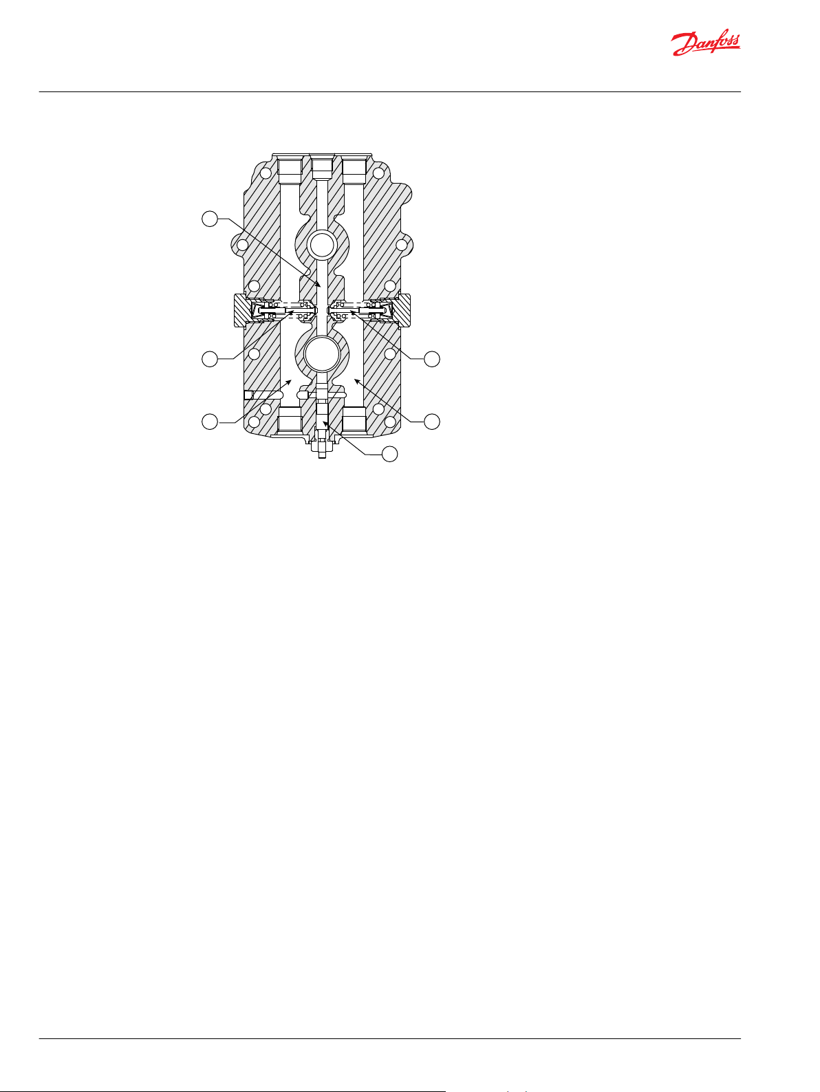
Design
Cross-Section (BDU-10S)
1. Tank 7. Spool type bypass valve 13. Shaft seal
2. Built-in filter 8. Cylinder block 14. Input shaft
3. Spring 9. Piston 15. Cooling fan
4. Center section 10. Thrust bearing 16. Cradle swash plate
5. Output shaft 11. Housing
6. Spring 12. Ball bearing
6 | © Danfoss | November 2021 BC152886484098en-000207
Page 7

P400203
18
22
3
4
5
11
10
9
8
7
6
20
19
1
17
16
15
14
1312
Technical Information
BDU Series Hydrostatic Transmissions
General Description
1. Suction Circuit 8. Charge Relief 15. Ball Bearing
2. Working Loop 9. Charge Circuit 16. Shaft Seal
3. Charge Check Valve 10. Output Shaft 17. Input Shaft
4. Spool Type Bypass Valve 11. Center Section 18. Cradle Swash Plate
5. Center Section 12. Cylinder Block 19. Piston
6. Suction Port 13. Thrust Bearing 20. Spring
7. Charge Pump 14. Housing
©
Danfoss | November 2021 BC152886484098en-000207 | 7
Page 8
Bypass
Valve
Cylinder
Block
Assembly
Input
Shaft
Variable
Swashplate
Variable
Displacement
Pump
BDU
Housing
Reservor
Built-In
Filter
(BDU-10S)
Check Valve
Check Valve
Cylinder Block
Assembly
Output
Shaft
Displacement
Motor
P400204
Fixed
Swashplate
Fixed
Working Loop
(high pressure)
Working Loop
(low pressure)
Suction Line
Case Drain Fluid
Control Shaft “b”
Control Shaft “a”
Hydraulic Circuit
ø0.7 ø0.8
P400205
Ø0.7 Ø0.8
1
1
2
2
3
3
Technical Information
BDU Series Hydrostatic Transmissions
General Description
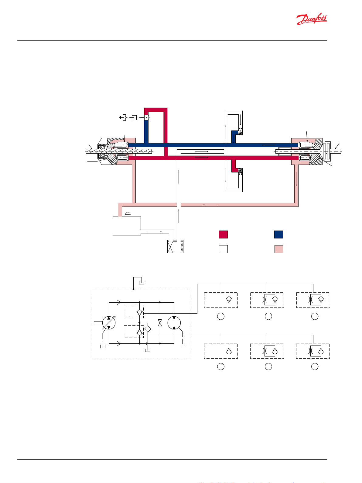
BDU-06/10S
Pictorial Diagram
BDU-06S, BDU-10S
System Schematic
1. Ball Check Valve, Option Code. : BB
2. Check Valve with Ø0.7 Orifice, Option Code : 07
3. Check Valve with Ø0.8 Orifice, Option Code : 08
8 | © Danfoss | November 2021 BC152886484098en-000207
Page 9
Bypass
Valve
Cylinder
Block
Assembly
Input
Shaft
Variable
Swashplate
Variable
Displacement
Pump
Reservor
Filter
Check Valve
Check Valve
Cylinder Block
Assembly
Output
Shaft
Fixed
Swashplate
Cooling
Orifice
Charge
Pump
Charge
Relief
Valve
Displacement
Motor
Fixed
P400206
Working Loop
(high pressure)
Working Loop
(low pressure)
Suction Line
Case Drain Fluid
Control Shaft “b”
Control Shaft “a”
Hydraulic Circuit
Suction Port Drain Port
Ø1.0 Ø1.2
Ø1.0
Ø0.8
Ø1.2
BDU-21L
P400207
1
1
2
2
3
3
Technical Information
BDU Series Hydrostatic Transmissions
General Description
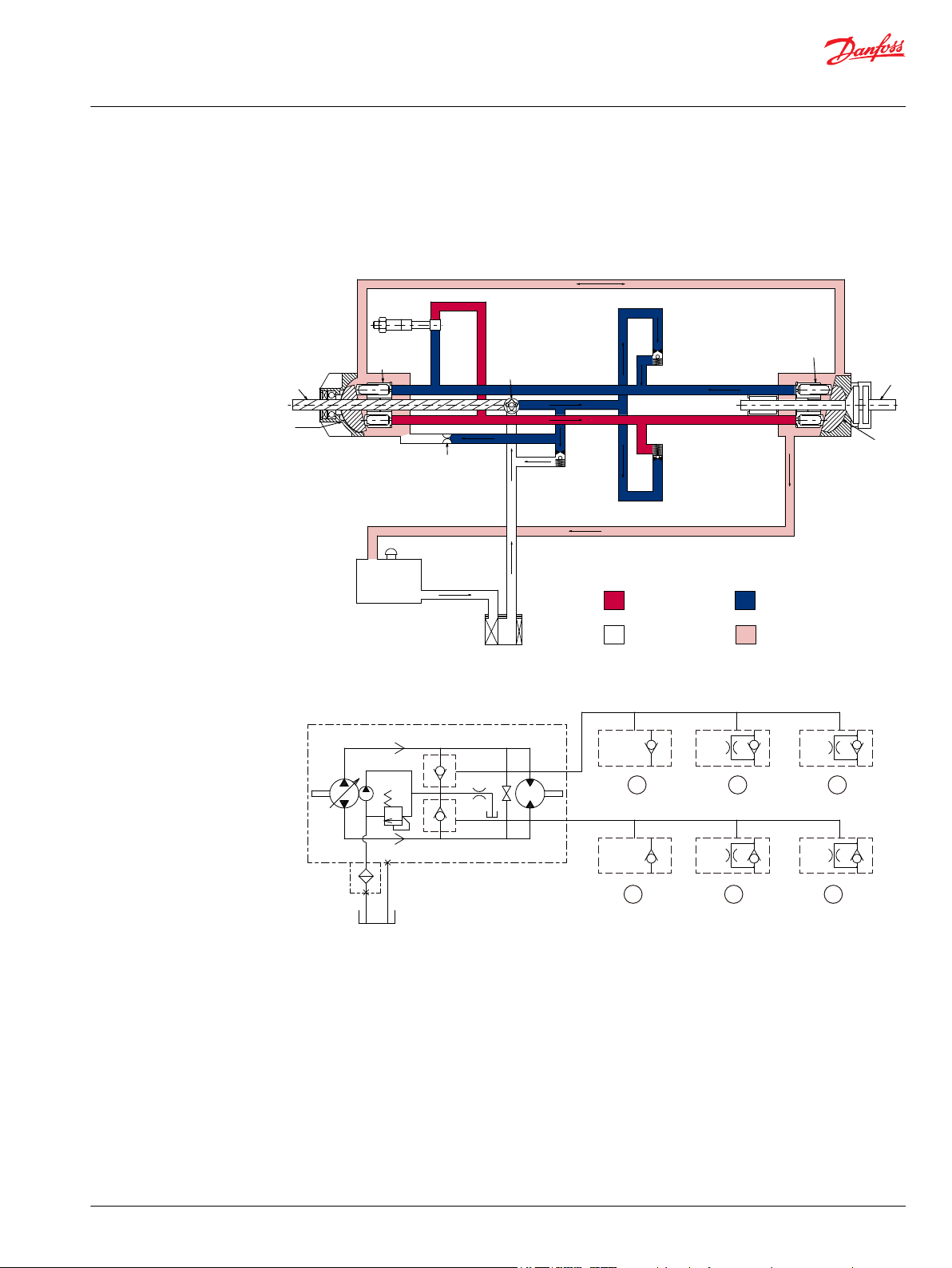
BDU-10L/21L/21H
Pictorial Diagram
BDU-10L, BDU-21L, BDU-21H (part of pump)
System Schematic: BDU-21L
1. Ball Check Valve, Option Code. : BB
2. Check Valve with Ø1.0 Orifice, Option Code : 10
3. Check Valve with Ø1.2 Orifice, Option Code : 12
©
Danfoss | November 2021 BC152886484098en-000207 | 9
Page 10

20.6MPa 17.2MPa 13.7MPa 20.6MPa 20.6MPa
20.6MPa 17.2MPa 13.7MPa 20.6MPa 20.6MPa
Control Shaft “b”
Control Shaft “a”
Hydraulic Circuit
Suction Port Drain Port
Ø0.8
ø0.85
ø0.85
ø0.7
×2
BDU-21H
ø0.7
×2
P400208
1 2 3 4 5
1 2 3 4 5
Technical Information
BDU Series Hydrostatic Transmissions
General Description
System Schematic: BDU-21H
1. Check Valve with Relief Valve, Option Code. : R0
2. Check Valve with Relief Valve, Option Code. : R1
3. Check Valve with Relief Valve, Option Code. : R2
4. Check Valve with Relief Valve and Ø0.7 Twin Orifice, Option Code. : RA
5. Check Valve with Relief Valve and Ø0.85 Orifice, Option Code. : RB
10 | © Danfoss | November 2021 BC152886484098en-000207
Page 11

Technical Information
BDU Series Hydrostatic Transmissions
Technical Specifications
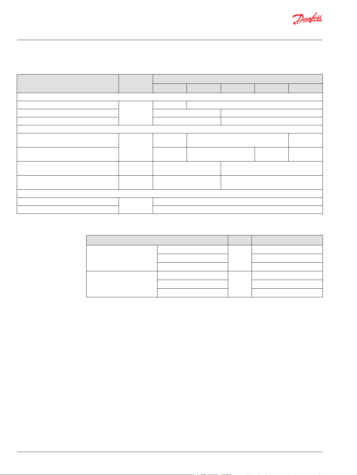
Features and Options
Features Unit
Displacement cm3 [in3]
Pump
Motor
Charge Pump Displacement cm3 [in3] NA NA
Output Speed
Maximum Output Torque (Theoretical) Nm [lbf•in]
Input Power (Maximum) kW [ps]
Weight kgf [lbs]
Control Torque Required to Stroke Pump
(Maximum)
Mounting See Installation Drawings
Rotation Clockwise or Counterclockwise
Suction/Oil Tank Port (SAE O-ring Boss) 7/8-14 UNF 7/16-20 UNF 9/16-18 UNF
Other ports See Installation Drawings
Shaft See Installation Drawings
Bypass Valve OP STD STD STD STD
Neutral Valve/Orifice NA/NA NA/OP NA/OP OP/OP OP/OP
High Pressure Relief Valve NA NA NA NA STD
Filtration W/O built-in External External (Option, Integrated)
Reservoir Integrated Integrated External External
Space for the oil in the housing cm
Swashplate Angle degree 15 15 15 15 15
Control Shaft degree 15 21 21 22 22
Displacement cm3 [in3]
Swashplate Angle degree 15 15 15 15 15
Rated
Maximum
(intermittent)
-1
min
Nm [lbf•in]
3
BDU-06S BDU-10S BDU-10L BDU-21L BDU-21H
6
[0.37]
6
[0.37]
3000 3000 3600 3600 3600
3200 3200 3800 3800 3800
9.8
[87]
1.1
[1.5]
4
[9]
8.8
[78]
450 550 550 700 700
Product Type & Frame
10
[0.61]
10
[0.61]
23.4
[208]
2.2
[3.0]
6.3
[14]
19.6
[174]
10
[0.61]
10
[0.61]
1.9
[0.12]
23.4
[208]
3.7
[5.0]
6.5
[14]
19.6
[174]
21
[1.28]
21
[1.28]
2.1
[0.13]
49.2
[436]
7.4
[10.0]
10
[22]
22.5
[200]
21
[1.28]
21
[1.28]
3.0
[0.18]
72.1
[639]
11.0
[15.0]
10
[22]
24.5
[217]
SAE J1926-1 / ISO 11926-1
©
Danfoss | November 2021 BC152886484098en-000207 | 11
Page 12
Technical Information
BDU Series Hydrostatic Transmissions
Technical Specifications
Operating Parameters
Parameter Unit
Input Speed
Minimum
Rated 3000 3600
Maximum 3200 3800
System Pressure
Maximum Working
Maximum
Charge Pressure
Charge Inlet Pressure
Case Pressure
Rated
Maximum (Cold Start) 0.7 [10]
min
[psi]
[psi]
[psi]
[psi]
Fluid Specifications
Features Units BD Series
Viscosity
Temperature
bar
bar
bar
bar
Product Type & Frame
BDU-06S BDU-10S BDU-10L BDU-21L BDU-21H
1000 600
-1
105
[1530]
150
[2185]
NA 3 [44] - 5 [73]
NA 0.8 [12] abs
Minimum
Continuous 12-60 [66-280]
Maximum 1600 [7500]
Minimum
Maximum Continuous 82 [180]
Maximum 104 [219]
[2549]
175
150
[2185]
0.3 [4]
mm2/sec.
[ SUS]
°C [°F]
210
[3059]
210
[3059]
245
[3569]
7 [49]
-10 [14]
12 | © Danfoss | November 2021 BC152886484098en-000207
Page 13

100
Efficiency %
90
80
70
60
50
40
30
20
10
0
3 5 7
Theoretical Output Torpue Nm
40%
40%
50%
50%
55%
55%
60%
60%
65%
65%
70%
70%
45%
45%
10
5
0 1000 2000 3000
Output Torque Nm
Output Speed min
-1
P400210
100
90
80
70
60
50
40
30
20
10
0
5 9 11 13 17
Efficiency %
Theoretical Output Torpue Nm
40%
45%
50%
55%
60%
65%
70%
73%
73%
70%
65%
60%
55%
50%45%
40%
20
10
0 1000 2000 3000
Output Torque Nm
Output Speed min
-1
P400211
100
90
80
70
60
50
40
30
20
10
0
5 5 7 9 11 13 15 16 18 20 22
Efficiency %
Theoretical Output Torpue Nm
40%
45%
50%
55%
60%
65%
70%
73%
73%
70%
65%
60%
55%
50%45%
40%
20
10
0
1000 2000 3000
P400212
Output Torque Nm
Output Speed min
-1
Technical Information
BDU Series Hydrostatic Transmissions
Technical Specifications
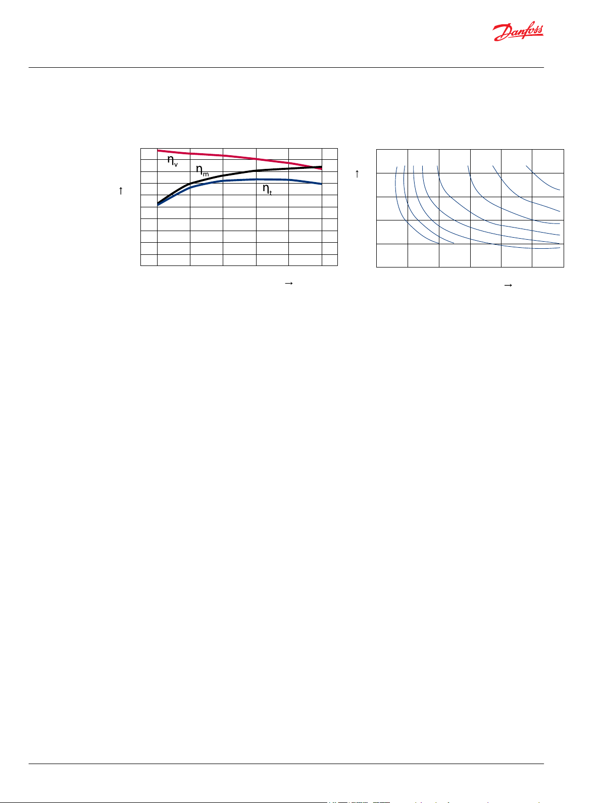
Efficiency
Input speed: 3000 min-1, Oil temperature: 50 °C, Full Displacement
BDU-06S
Efficiency (ηv:Volumetric, ηm:Mechanial, ηt:Overall)
BDU-10S
Efficiency (ηv:Volumetric, ηm:Mechanial, ηt:Overall)
BDU-10L
Efficiency (ηv:Volumetric, ηm:Mechanial, ηt:Overall)
©
Danfoss | November 2021 BC152886484098en-000207 | 13
Page 14
100
90
80
70
60
50
40
30
20
10
0
11 23 34 46 57 65
Efficiency %
Theoretical Output Torpue Nm
40%
45%
50%
55%
60%
65%
70%
75%
70%
75%
65%
60%
55%
50%
45%
40%
50
40
30
20
10
0
1000 2000 3000
Output
Torque Nm
Output Speed min
-1
P400213
Technical Information
BDU Series Hydrostatic Transmissions
Technical Specifications
BDU-21L/21H
Efficiency (ηv:Volumetric, ηm:Mechanial, ηt:Overall)
14 | © Danfoss | November 2021 BC152886484098en-000207
Page 15

W
Technical Information
BDU Series Hydrostatic Transmissions
Operating Parameters
Overview
Maintain operating parameters within prescribed limits during all operating conditions. This section
defines operating limits given in the table Operating Parameters.
Input Speed
Minimum speed is the lowest input speed recommended during engine idle condition. Operating below
minimum speed limits pump’s ability to maintain adequate flow for lubrication and power transmission.
Rated speed is the highest input speed recommended at full power condition. Operating at or below
this speed should yield satisfactory product life.
Maximum speed is the highest operating speed permitted. Exceeding maximum speed reduces product
life and can cause loss of hydrostatic power and braking capacity. Never exceed the maximum speed
limit under any operating conditions.
Operating conditions between rated speed and maximum speed should be restricted to less than full
power and to limited periods of time. For most drive systems, maximum unit speed occurs during
downhill braking or negative power conditions.
System Pressure
Charge Pressure
Warning
Unintended vehicle or machine movement hazard.
Exceeding maximum speed may cause a loss of hydrostatic drive line power and braking capacity. You
must provide a braking system, redundant to the hydrostatic transmission, sufficient to stop and hold the
vehicle or machine in the event of hydrostatic drive power loss.
System pressure is the differential pressure between system ports A & B. It is the dominant operating
variable affecting hydraulic unit life. High system pressure, which results from high load, reduces
expected life. Hydraulic unit life depends on speed and normal operating—or weighted average—
pressure that you can only determine from a duty cycle analysis.
Maximum Working Pressure is the highest recommended Application pressure. Maximum working
pressure is not intended to be a continuous pressure. Propel systems with Application pressures at, or
below, this pressure should yield satisfactory unit life given proper component sizing.
Maximum pressure (peak) is the highest intermittent pressure allowed under any circumstances.
Applications with applied pressures between rated and maximum require factory approval with
complete application, duty cycle, and life expectancy analysis.
All pressure limits are differential pressures referenced to low loop (charge) pressure. Subtract low loop
pressure from gauge readings to compute the differential.
The charge pressure setting listed in the technical specifications is based on the charge flow across the
charge pressure relief valve at fluid temperature at 50˚C [120˚F].
Charge Inlet Pressure
Charge pump inlet conditions must be controlled in order to achieve expected life and performance. A
continuous inlet vacuum of no less than 0.8 abs bar is recommended. Normal vacuums less than 0.7 abs
bar would indicate inadequate inlet design or stricted filter.
©
Danfoss | November 2021 BC152886484098en-000207 | 15
Page 16

C
C
Technical Information
BDU Series Hydrostatic Transmissions
Operating Parameters
Case Pressure
Under normal operating conditions, the maximum continuous case pressure must not exceed 0.3 bar
(4PSI). Maximum allowable intermittent case pressure during cold start must not exceed 0.7 bar (10PSI).
Caution
Possible component damage or leakage
Operation with case pressure in excess of stated limits may damage seals, gaskets, and/or housings,
causing external leakage. This condition may also affect performance since charge and system pressure
are referenced to case pressure.
Hydraulic Fluids
Ratings and data are based on operating with hydraulic fluids containing inhibitors to prevent oxidation,
rust, and foam. These fluids must possess good thermal and hydrolytic stability to prevent wear, erosion,
and corrosion of the internal components.
Caution
Never mix hydraulic fluids of different types.
Temperature and Viscosity
Temperature and viscosity requirements must be concurrently satisfied. The data shown in the table Fluid
Specifications on page 12, assume petroleum-based fluids are used.
The high temperature limits apply at the hottest point in the transmission, which is normally the motor
case drain. The system should generally be run at or below the rated temperature. The maximum
temperature is based on material properties and should never be exceeded.
Cold oil will generally not affect the durability of the transmission components, but it may affect the
ability of oil to flow and transmit power; therefore temperatures should remain 16 °C [30 °F] above the
pour point of the hydraulic fluid. The minimum temperature relates to the physical properties of
component materials.
For maximum unit efficiency and bearing life the fluid viscosity should remain in the recommended
operating range. The minimum viscosity should be encountered only during brief occasions of
maximum ambient temperature and severe duty cycle operation. The maximum viscosity should be
encountered only at cold start.
Heat exchangers should be sized to keep the fluid within these limits. Testing to verify that these
temperature limits are not exceeded is recommended.
16 | © Danfoss | November 2021 BC152886484098en-000207
Page 17

W
Technical Information
BDU Series Hydrostatic Transmissions
System Design Parameters
Fluid and Filtration
To prevent premature wear, it is imperative that only clean fluid enters the hydrostatic transmission
circuit. Therefore an inlet filter better than β20=1.4 is required in the charge pump inlet line. This filter
should not have a bypass and should be changed regularly to ensure system reliability. The BD series
hydrostatic transmission requires system filtration capable of maintaining fluid cleanliness at ISO
4406-1999 class 22/18/15 or better.
Reservoir
The BDU-06S and BDU-10S are designed with optional integrated reservoir. A reservoir for BDU-10L larger
than the 2 liter tank size is recommended. A reservoir for BDU-21L/H larger than the 5 liter tank size is
recommended. The hoses or piping size is recommended to be larger than 3/8 inch normal tube OD.
Control Shaft Force
The BDU transmission is designed with direct displacement control (DDC). DDC can be located at either
side of the housing. It provides a simple, positive method of control. Movement of the control shaft
causes a proportional swashplate movement, thus varying the pump’s displacement from full
displacement in one direction to full displacement in the opposite direction.
The approximate maximum control torque necessary to rotate the control shaft is shown in the table of
technical specifications. A stopper to prevent over-stroke is required at the end of maximum angle of
control shaft. The control shaft force should be kept at or below the force in the table below.
Independent Braking System
Features Unit
Allowable maximum force for control shaft Nm 10 20 25
Vehicle propel applications may require a provision for non-linear control input to reduce control
sensitivity near neutral. Damping or frictional forces may be necessary to produce the desired control
feeling.
These units do not include any neutral centering device for the swashplate. It is necessary to provide a
force in the machine’s control system that will hold the swashplate at the desired angle. A “ fail safe
“ which will return the swashplate to the neutral in the event of linkage failure is recommended.
Warning
Unintended vehicle or machine movement hazard.
The loss of hydrostatic drive line power, in any mode of operation (forward, neutral, or reverse) may cause
the system to lose hydrostatic braking capacity. You must provide a braking system, redundant to the
hydrostatic transmission, sufficient to stop and hold the vehicle or machine in the event of hydrostatic
drive power loss.
BDU-06S BDU-10S BDU-21L
Product type & Frame
©
Danfoss | November 2021 BC152886484098en-000207 | 17
Page 18

No Load
No Load
No Load
T
out
(No Load)
T
in
Distance (L)
P400215
R
e
BDU-21L/21H
200
400
600
800
1000
1200
1400
0 10-10 20 30 40 50
BDU-10S/10L
200
400
600
800
0 10 20 30 40 50
0 10
200
400
600
BDU-06S
20 30
distance (L) mm → distance (L) mm → distance (L) mm →
Re N →
Re N →
Re N →
P400216
Technical Information
BDU Series Hydrostatic Transmissions
Features and Options
Shaft Load
The maximum allowable radial road of input shaft (Re) is based on the maximum external moment and
the distance from the housing surface to the input shaft. The limit of radial load of input shaft is shown
the figure below:
Shaft Options
The maximum shaft thrust in (Tin) of input shaft is 18% of allowable radial road (Re) of the input shaft.
The shaft thrust out (Tout) of the input shaft should be no load. The radial and thrust load of the output
shaft should be no load.
The BDU transmissions are available with a variety of straight key, JIS Spline, JIS Serration, SAE Spline
shaft for input shaft, PTO shaft and output shaft. Details are shown in the Installation Drawings on page
35.
18 | © Danfoss | November 2021 BC152886484098en-000207
Page 19

A
B
C
P400217
D
d
D
Technical Information
BDU Series Hydrostatic Transmissions
Features and Options
Shaft Options : BDU-06S/10S/10L
Output Shaft Options
Output Shaft Code BDU-06S BDU-10S BDU-10L
Shafts:
A = Output Shaft
B = PTO Shaft
C = Input Shaft
15 x 13 x 1.0 J13
JIS Spline
20 x 18 x 1.0 K18
SAE Spline 32/64-16T S16
PTO Shaft / Input Shaft Options
PTO Shaft Input Shaft Code BDU-06S BDU-10S BDU-10L
KA0
KB0
None
Straight-Keyed D =
15 mm
KB1
PB1
Straight d =
12.7 mm
Straight-Keyed D =
15 mm
PB3
©
Danfoss | November 2021 BC152886484098en-000207 | 19
Page 20

D
A
P400355
B
C
Technical Information
BDU Series Hydrostatic Transmissions
Features and Options
PTO Shaft / Input Shaft Options (continued)
PTO Shaft Input Shaft Code BDU-06S BDU-10S BDU-10L
PB2
JIS Serration
12 x 23 x 0.5
Shaft Options : BDU-21L/21H
Output Shaft Options
Straight-Keyed D =
15 mm
This charge pump housing is applied only for BDU-10L.
Output Shaft Code BDU-21L BDU-21H
PB4
Shafts:
A = Output Shaft
B = PTO Shaft
C = Input Shaft
20 x 14 x 1.25 J14
JIS Spline
20 x 18 x 1.0 J18
SAE Spline 32/64-22T S22
20 | © Danfoss | November 2021 BC152886484098en-000207
Page 21

D
D
D
Technical Information
BDU Series Hydrostatic Transmissions
Features and Options
PTO Shaft / Input Shaft Options
PTO Shaft Input Shaft Code BDU-21L BDU-21H
KC1
None
JIS Spline
15 x 13 x 1.0
SAE Spline
32/64-16T
Bypass Valve
Straight-Keyed D =
17 mm
Straight-Keyed D =
17 mm
Straight-Keyed D =
17 mm
KC2
PC1
PC2
PC3
PC5
In some applications, it is desirable to move the vehicle over short distances at low speed without
starting the engine. A bypass valve allows oil to be routed from one side of the pump/motor circuit to the
other, thus allowing the motor to turn. The bypass valve must be fully closed during normal vehicle
operation. BDU series transmissions utilize a spool-type bypass valve. The bypass valve plunger must be
depressed manually to open the valve. This connects both sides of the main hydraulic circuit to the
housing case and allows fluid to circulate without rotating the pump, prime mover and motor. A spring
closes this valve on the 6S, 10L and 10S transmissions, while charge pressure closes the valve on the 21L
and 21H transmissions.
High Pressure Relief Valve (hprv) and Charge Check (Overpressure Protection)
The BDU-21H transmission is available with a combination charge check and high pressure relief valve
assembly. High pressure relief valves are available in a range of settings as shown in the Model Code on
page 31. Individual port pressure settings may be specified. The high pressure relief valve settings are a
differential pressure (referenced to charge pressure).
Check and Relief Valve for BDU-21H
Option Code
R0 210 R1 175 R2 140 RA 210 0.7 Twin
RB 210 0.85
©
Danfoss | November 2021 BC152886484098en-000207 | 21
Pressure setting
bar [psi]
Orifice
Page 22
P400219
1
2
3
6
5
4
Technical Information
BDU Series Hydrostatic Transmissions
Features and Options
1. Charge circuit
2. Check and relief valve
3. Working loop (Main hydraulic circuit
4. Bypass valve
5. Working loop (Main hydraulic circuit)
6. Check and relief valve
22 | © Danfoss | November 2021 BC152886484098en-000207
Page 23

with Orifice
Reverse
DB-OR
Neutral-OR
Neutral-STD
DB-STD
Control Shaft Angle
Forward
Output Flow
P400220
Technical Information
BDU Series Hydrostatic Transmissions
Features and Options
Charge Check Valve with Orifice
The BDU transmissions are equipped with charge check valves. In some applications, it is desirable to use
charge check valve with orifice for expanding null dead band, giving both the safety measure to prevent
the vehicle movement in the neutral position of the control shaft and easy adjustment of neutral position
when connected to vehicle linkage. The orifice connects the working loop, which is a main hydraulic
circuit, to a charge circuit. It always allows some internal leakage to ensure the expanding null dead band
around neutral position of control shaft. However, it decreases the volumetric efficiency, particularly at
high system pressure in the working loop. It is recommended to install the orifice in a specific working
loop, which is pressurized when the vehicle moves in reverse. The orifice diameter improves the null
dead band but decreases the volumetric efficiency. A cross section and characteristics are shown below.
The charge check valves with orifice are available in a range of orifice diameters as shown in the Model
Code on page 31.
Input Speed: 3000min-1, Oil Temp: 50 °C , No Load
Features Unit
Deadband of Control Shaft Angle
(DB-STD)
©
Danfoss | November 2021 BC152886484098en-000207 | 23
Features Unit
Deadband of Control Shaft Angle
(DB-OR)
[degree] Approx. 0.1
BDU-10S/10L BDU-21L BDU-21H
Ø 0.7 Ø 0.8 Ø 1.0 Ø 1.2 Ø 0.85 Ø 0.7 twin
[degree]
Approx.
0.5
Approx.
BDU-10S/10L/21L/21H
Without Orifice
Orifice diameter [mm]
0.7
Approx.
0.5
Approx.
0.7
Approx.
0.35
Approx.
0.5
Page 24
P400221
P400222
P400223
P400224
Orifice
P400225
P400226
P400227
Orifice
P400228
P400229
P400230
Orifice
Technical Information
BDU Series Hydrostatic Transmissions
Features and Options
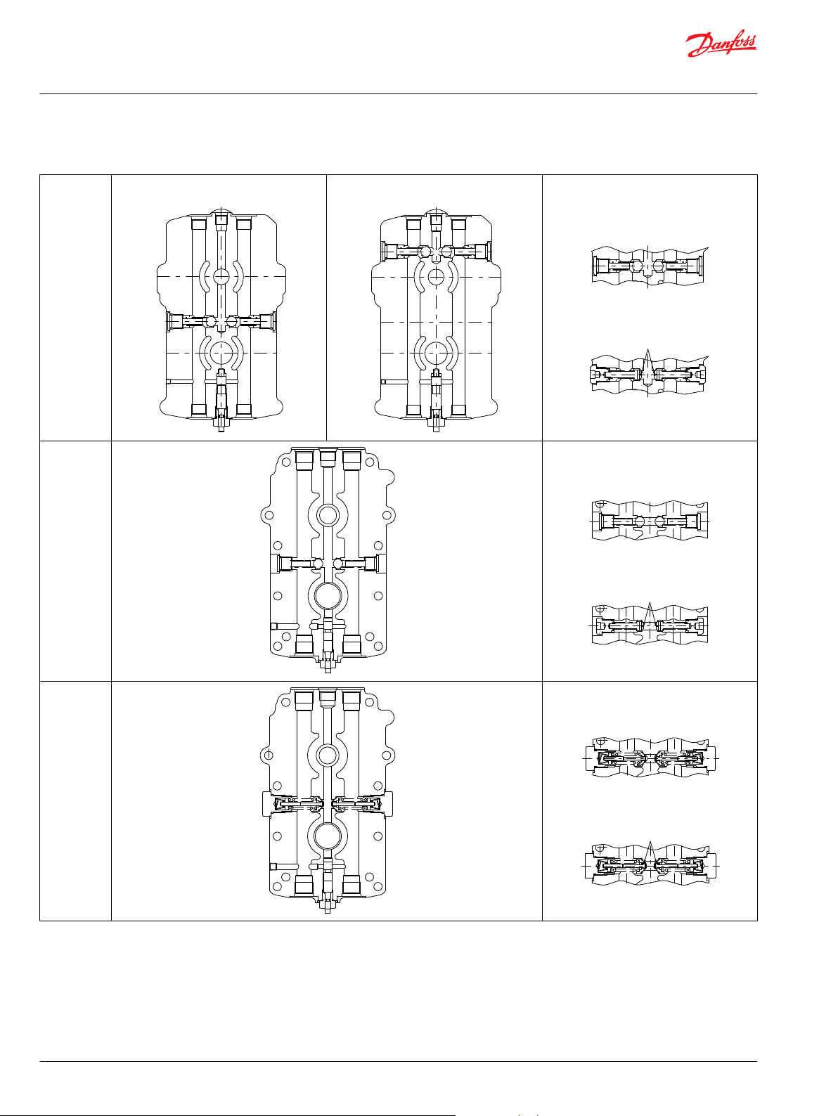
Charge Check with Orifice
BDU-10S
BDU-10L
BDU-21L
BDU-10L Check Valve
BDU-10S Check Valve
Check Valve (Ball) without Orifice
Check Valve with Orifice
Check Valve (Ball) without Orifice
Check Valve with Orifice
Check & Relief without Orifice
BDU-21H
Check & Relief with Orifice
24 | © Danfoss | November 2021 BC152886484098en-000207
Page 25

25.51415
7/8-14UNF
P400231
30
-0.8
0
Dimensions of
Widths Across
Flats of Hexagon
Ø 71
Ø 60
75.5 ± 1.5
P/N BDU-10S-TANK
70.8
69
32
3/4-16 UNF screw
3/4-16 UNF screw
Screwed Type
P/N H-3101069
P/N 05EL-BD
Steel Pipe Fitting
Ø 37
Ø 59.7
Ø 84
P400232
Technical Information
BDU Series Hydrostatic Transmissions
Features and Options
Optional Integrated Reservoir
The BDU-06S and BDU-10S are designed with optional integrated reservoir. The optional Integrated
reservoir is shown in the figure on the right.
Filter
The BDU-10S is designed with Built-in filter. BDU-21L/H is designed with optional Integrated filter, which
is shown in the figure on the right. The filter connection is designed with consideration given to the
screwed type steel pipe fitting that is an option. An external filter is required in the charge pump inlet line
for BDU- 10L. This filter should not have a bypass and should be changed regularly to ensure system
reliability.
©
Danfoss | November 2021 BC152886484098en-000207 | 25
Page 26
CCW
31.8
Rotation
Wind
Ø 7.1
Ø 177.8
P400233
Technical Information
BDU Series Hydrostatic Transmissions
Features and Options
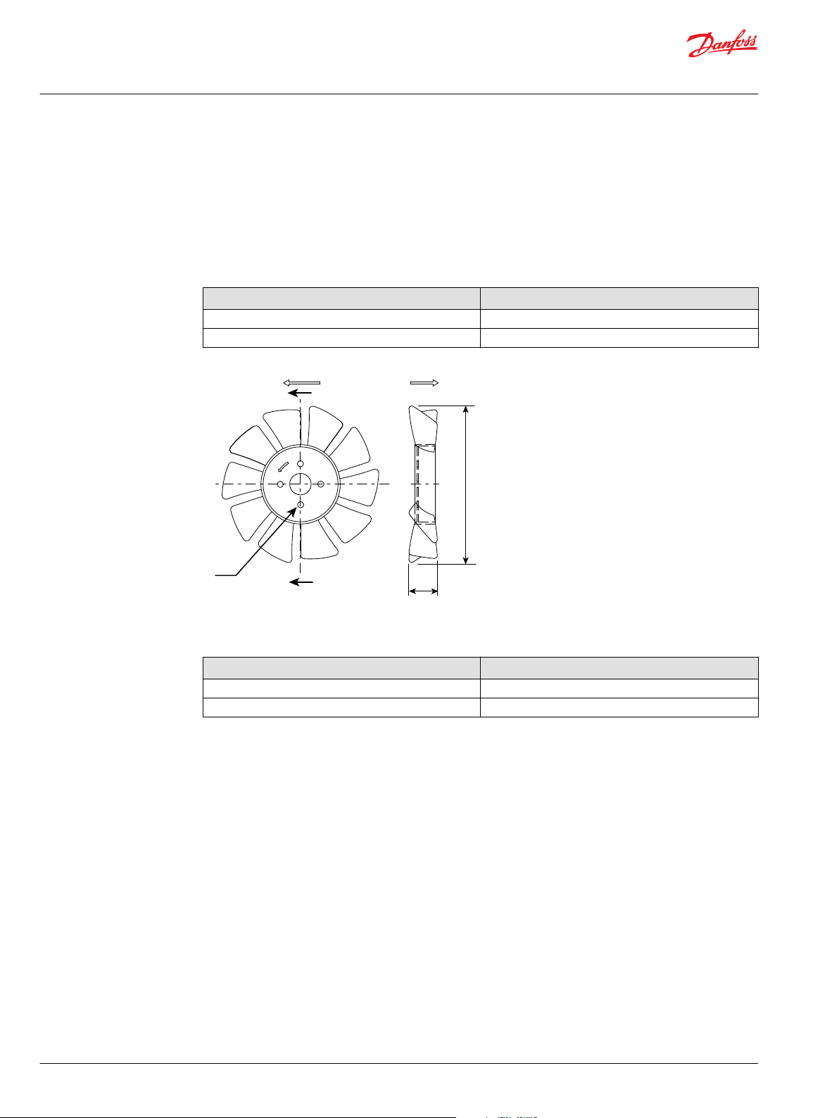
Fan
The operating temperature of the BDU transmission becomes hot when operated at a heavy load for
long, continuous time. To avoid a reduction in the life of the BDU transmission or risking immediate
failure, a cooling fan may be installed on the input shaft or external reservoir to be effective as heat
exchanger may be installed. The BDU transmission is available with optional fan integrated with the belt
drive device for the input shaft. The detailed outlines are shown in the Installation Drawings on page 35.
Optional Fan for Cooling
P/N Rotation
H-1030826 CW
H-1030827E CCW
Optional Fan for Cooling
P/N Rotation
H-1030826 CW
H-1030827E CCW
26 | © Danfoss | November 2021 BC152886484098en-000207
Page 27

Technical Information
BDU Series Hydrostatic Transmissions
Component Selection
Selecting the proper transmission for a vehicle begins with determining the maximum system pressure
by using tractive effort of the vehicle and the maximum vehicle speed required. The transmission
selected must meet both requirements.
Maximum System Pressure
Maximum operating system pressure should be calculated at maximum tractive effort condition.
Maximum tractive effort condition is assumed at vehicle with maximum weight transfer from pushing or
pulling implements at maximum grade of slope. First, calculate BDU motor torque by using the following
equation:
Equation-1
MTQ_ME = Output torque of BDU motor at maximum tractive effort condition in Nm
•
PR_ME = Pull Ratio at maximum tractive effort (See below)
•
VW_ML = Gross vehicle weight with maximum loaded weight in kgf
•
LR = Tire Radius in meters
•
FDR = Transaxle Final Drive Ratio
•
EFF_FD = Transaxle Final Drive Efficiency
•
The hydrostatic transmissions in many applications are used in conjunction with readily available
transaxles. In order to meet both requirements of high output torque at operating mode and high speed
at traveling mode, the transaxles with two kinds of shifts, Hi and Lo are used in some applications. In such
transaxles, use Lo shift ratio as FDR in equation-1 and -4 to calculate maximum system pressure.
A useful parameter for determining tractive effort is "Pull Ratio". Pull Ratio is a dimensionless term that is
the ratio of tractive effort to gross vehicle weight. It is generally constant for each class of vehicle. These
values may be used when actual vehicle tractive efforts are not known. In a typical agriculture application
for BDU application, Pull Ratio for the highest load mode can be calculated from the primary components
of pull ratio: rolling resistance, grade motion resistance by a function of slope, machine function motion
resistance and drive configuration motion resistance. In such cases, pull ratio is determined by using the
following equation:
Equation-2
•
RR = Rolling resistance. See SD Application manual
•
GR = Motion resistance of Grade. See SD Application manual
•
MF = Machine function motion resistance, See SD Application manual
•
DC = Drive configuration motion resistance, See SD Application manual
Then, maximum system pressure can be calculated by using MTQ_ME and the following quation:
Equation-3
©
Danfoss | November 2021 BC152886484098en-000207 | 27
Page 28

Technical Information
BDU Series Hydrostatic Transmissions
Component Selection
•
SPR_ME = Maximum BDU system pressure operated at Maximum tractive effort mode in bar
•
DP = Motor Displacement of selected BDU transmissions in cm
•
MEF_MO = Motor Mechanical Efficiency of BDU transmission in this mode
Select appropriate BDU size which will give SPR_ME, not to exceed the value of maximum system
pressure allowed in the technical specification, because BDU is generally applied without system
pressure relief valves.
If appropriate BDU size satisfies maximum system pressure, determine the BDU output speed at
maximum tractive effort mode by using the following equation:
Equation-4
•
MSP_ME = The BDU output speed at maximum tractive effort condition in min-1 (rpm)
•
VSP_ME = The vehicle speed requested for maximum tractive effort mode in m/s
Confirm the BDU output speed calculated to satisfy the maximum output speed (intermittent) in the
technical specification.
3
Input Power
Calculate required input power of BDU by using the following equation:
Equation-5
PW_ME = BDU Input power required for maximum tractive effort mode in kW
•
OEF_BDU = BDU unit overall efficiency for this mode
•
If PW_ME is larger than Input power (Maximum) of selected BDU, VSP_ME should be limited to satisfy
maximum BDU input power. If the calculated speed exceeds the technical specification, the transaxle
final drive ratio or tire size may need to be changed.
Maximum vehicle speed is generally recommended in traveling mode. Calculate maximum BDU speed by
using the following equation:
Equation-6
•
MSP_TR = The BDU output speed for traveling mode in min-1 (rpm)
•
VSP_TR = The vehicle speed requested for traveling mode in m/s
Use Hi shift ratio as FDR in Equation-6 if the Transaxle Final Drive has two shifts.
Confirm MSP_TR to satisfy the maximum output speed (intermittent) in the technical specification. If
MSP_TR is not satisfied, FDR (Hi shift) may need to be changed. It is also necessary to determine the
system pressure for traveling mode (SPR_TR) to satisfy maximum system pressure (intermittent) allowed
in the technical specification. SPR_TR is calculated by using equation -1, -2 and -3 with parameters of
traveling mode.
28 | © Danfoss | November 2021 BC152886484098en-000207
Page 29
Technical Information
BDU Series Hydrostatic Transmissions
Component Selection
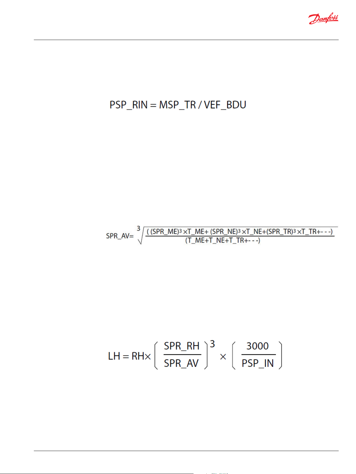
Calculate the required BDU input shaft speed to satisfy maximum BDU output shaft speed by using the
following equation:
Equation-7
•
PSP_RIN = required BDU input shaft speed in min-1 (rpm)
•
VEF_BDU = BDU volumetric efficiency for this mode
Confirm BDU input shaft speed is larger than PSP_RIN.
Unit Life
The unit life of selected BDU transmissions should be determined by using average system pressure
under overall operating modes, because vehicles generally operate in their maximum tractive effort
mode for a small percentage of their life. If a duty cycle for a transmission is known, weighted average
system pressure can be calculated and can estimate the life expectancy of the transmission selected. The
duty cycle can be assumed for instances including several modes. Calculate weighted average system
pressure by using the following equation:
Equation-8
SPR_AV = weighted average system pressure. This is the mean pressure of the duty cycle in bar
•
SPR_ME = the system pressure for maximum tractive effort mode and T_ME is its time in the duty
•
cycle
SPR_NE = the system pressure at the normal tractive effort which means with normal weight and at
•
0% Grade and T_NE is its time in the duty cycle
SPR_TR = the system pressure for traveling mode and T_TR is its time in the duty cycle
•
If needed, define other system pressures at other operating conditions and add them to the equation.
The BDU Unit Life hours at weighted average pressure is determined by using the following equation:
Equation-9
•
LH = Unit Life hours of selected BDU at the duty cycle estimated
•
SPR_RH = The system pressure at Rated Unit Life (See table A)
•
PSP_IN = The input shaft speed of BDU unit. Normally, input shaft speed of BDU is constant
Confirm LH of selected BDU to satisfy the Life requirement. If LH is shorter than the requested
specification, the next larger size transmission may be needed and the repeat the calculation for
Component Selection on other BDU using Equation -1 through -9. Contact Danfoss for assistance in
correct transmission selection.
©
Danfoss | November 2021 BC152886484098en-000207 | 29
Page 30

Technical Information
BDU Series Hydrostatic Transmissions
Component Selection
Table A
Parameter Unit
RH hour 300 300 1000 1600 2500
SPR_RH bar 55 70 70 70 70
BSP_OP min
BDU-06S BDU-10S BDU-10L BDU-21L BDU-21H
-1
3000 3000 3000 3000 3000
Frame
30 | © Danfoss | November 2021 BC152886484098en-000207
Page 31
JF GE H K
BDU -
B DCA
Technical Information
BDU Series Hydrostatic Transmissions
Model Code
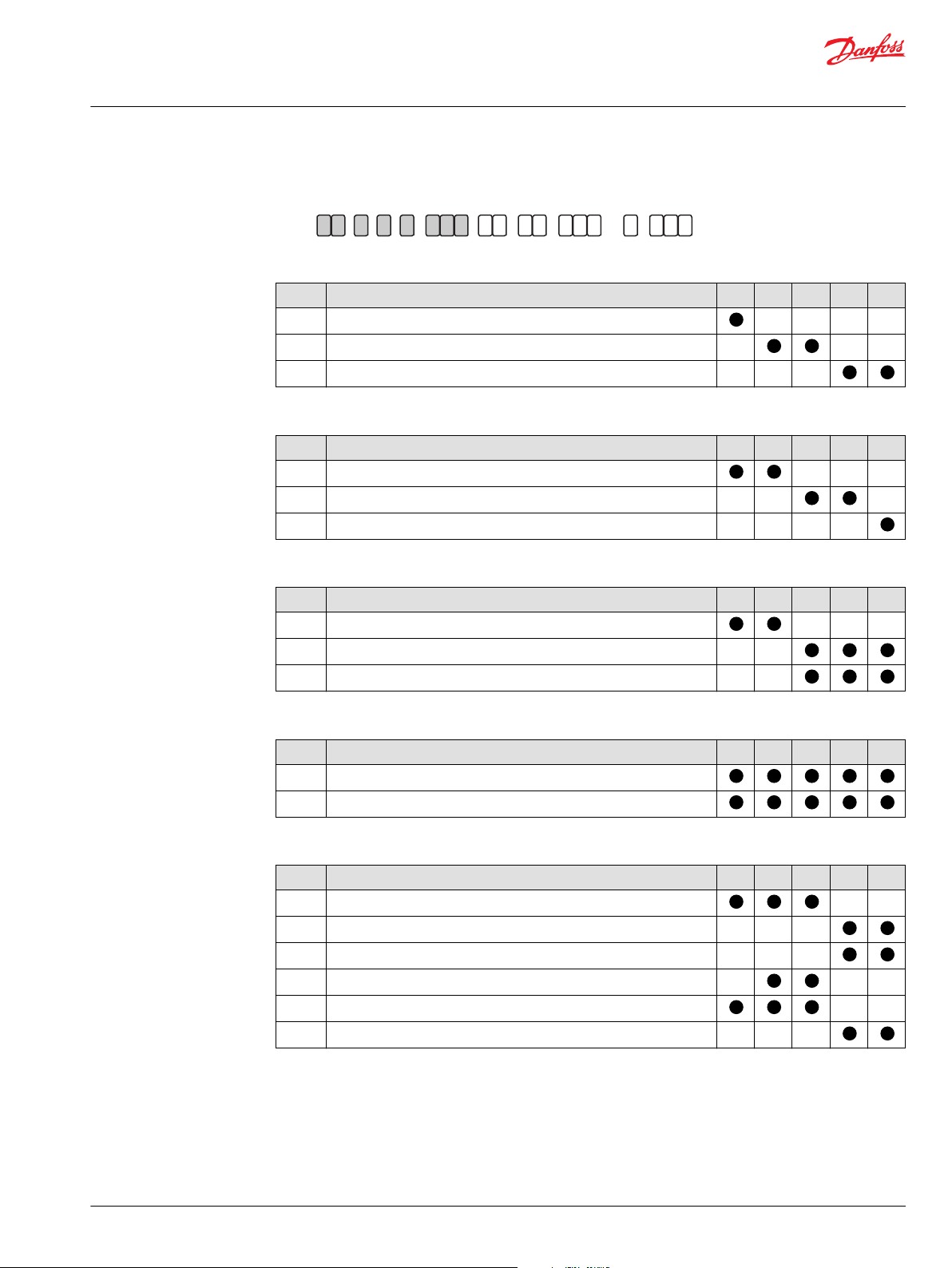
BDU : Model Code (A - B - C - D - E)
A - Displacement
Code Description 06S 10S 10L 21L 21H
06 6 cm
10 10 cm
21 21 cm
B - Design
Code Description 06S 10S 10L 21L 21H
S Standard
L Long Life
H High Pressure
3
3
3
C - Rotation
Code Description 06S 10S 10L 21L 21H
W Bi-directional rotation
R Clockwise rotation
L Counter-Clockwise rotation
D - Contrl Arm Location
Code Description 06S 10S 10L 21L 21H
R Right-hand side viewing from input shaft (pump located upside)
L Left-hand side viewing from input shaft (pump located upside)
E - Output Shaft
Code Description 06S 10S 10L 21L 21H
J13 JIS Spline 15×13×1.0
J14 JIS Spline 20×14×1.25
J18 JIS Spline 20×18×1.0
K18 JIS Spline 15×18×0.75
S16 SAE Spline 32/64 - 16T
S22 SAE Spline 32/64 - 22T
©
Danfoss | November 2021 BC152886484098en-000207 | 31
Page 32

JF GE H K
BDU -
B DCA
Technical Information
BDU Series Hydrostatic Transmissions
Model Code
BDU : Model Code (F - G)
F - Check & Relief Valve (Left-hand side viewing from Housing)
Code Description 06S 10S 10L 21L 21H
BB Ball Check Valve
00 Poppet-type Check Valve
07 Check Valve w/dia = 0.7 orifice
08 Check Valve w/dia = 0.8 orifice
10 Check Valve w/dia = 1.0 orifice
12 Check Valve w/dia = 1.2 orifice
R0 Check and High Pressure Relief Valve 210 bar
R1 Check and High Pressure Relief Valve 175 bar
R2 Check and High Pressure Relief Valve 140 bar
RA Check and High Pressure Relief Valve 210 bar w/dia=0.7 twin orifice
RB Check and High Pressure Relief Valve 210 bar w/dia=0.85 orifice
G - Check & Relief Valve (Right-hand side viewing from Housing)
Code Description 06S 10S 10L 21L 21H
BB Ball Check Valve
00 Poppet-type Check Valve
07 Check Valve w/dia = 0.7 orifice
08 Check Valve w/dia = 0.8 orifice
10 Check Valve w/dia = 1.0 orifice
12 Check Valve w/dia = 1.2 orifice
R0 Check and High Pressure Relief Valve 210 bar
R1 Check and High Pressure Relief Valve 175 bar
R2 Check and High Pressure Relief Valve 140 bar
RA Check and High Pressure Relief Valve 210 bar w/dia=0.7 twin orifice
RB Check and High Pressure Relief Valve 210 bar w/dia=0.85 orifice
32 | © Danfoss | November 2021 BC152886484098en-000207
Page 33

JF GE H K
BDU -
B DCA
Technical Information
BDU Series Hydrostatic Transmissions
Model Code
BDU : Model Code (H - J - K)
H - Input shaft / PTO shaft Configuration & Charge Pump Displacement
Code Description 06S 10S 10L 21L 21H
KAO Straight-keyed D=15mm shaft / None & w/o Charge Pump
KBO Straight-keyed D=15mm shaft / None & w/o Charge Pump
KB1 Straight-keyed D=15mm shaft / None & w/1.9cm3 Charge Pump
KC1 Straight-keyed D=17mm shaft / None & w/2.1cm3 Charge Pump
KC2 Straight-keyed D=17mm shaft / None & w/3.1cm3 Charge Pump
PB1 Straight-keyed D=15mm shaft /Straight 12.7 mm shaft & w/o Charge
Pump
PB2 Straight-keyed D=15mm shaft /JIS Serration 12 x 23 x 0.5 shaft & w/o
Charge Pump
PB3 Straigt-keyed D=15mm shaft /Straight 12.6 mm shaft & w/2.4cm
Charge Pump
PB4 Straight-keyed D=15mm shaft /JIS Serration 12 x 23 x 0.5 shaft & w/
2.4cm3 Charge Pump
PC1 Straight-keyed D=17mm shaft /JIS Spline 15 x 13 x 1.0 shaft & w/2.1cm
Charge Pump
PC2 Straight-keyed D=17mm shaft /JIS Spline 15 x 13 x 1.0 shaft & w/3.1cm
Charge Pump
PC5 Straight-Keyed D=17mm shaft /SAE Spline 32/64 -16T & w/2.1cm
Charge Pump
PC6 Straight-Keyed D=17mm shaft /SAE Spline 32/64 -16T & w/3.1cm
Charge Pump
3
3
3
3
3
J - Bypass & Nuetral Valve
Code Description 06S 10S 10L 21L 21H
N None
A w/Nuetral Valve Pressure 35 bar w/dia=1.0 orifice
B w/Bypass Valve
K - Special Hardware
Code Description 06S 10S 10L 21L 21H
NNN None
WOL Oil-filled in case
©
Danfoss | November 2021 BC152886484098en-000207 | 33
Page 34

Technical Information
BDU Series Hydrostatic Transmissions
Recommended Installation and Maintenance
Housing Installation
The center section of BDU transmission has 4 holes for fixing screws. The screws should be inserted in the
holes and tightened to specifications.
*Fitting Torque 1569 ~ 2058 N·cm
Shaft Installation
The input shaft of the BDU transmission should be connected to the prime mover by a belt drive device,
sheave or coupling. When using a belt drive device, the radial load on the input shaft should not exceed
the maximum allowable load shown in Shaft Load on page 18.
When installing the BDU motor shaft to the gearbox or to other devices directly, utilize the groove on the
center section of the BDU transmission, which is located concentric to the motor shaft, to ensure the
accuracy of concentricity. When using the coupling for connection of the shaft, ensure the accuracy of
concentricity is kept in the region of ±0.025mm. Do not beat the coupling strongly into the shaft with a
hammer.
It is recommended the shaft to be lubricated when using a spline shaft.
Start Up Procedure
After installing the BDU transmission and corresponding pipeline connection, remove the case drain port
plug from the housing. Fill the BDU transmission case with the recommended oil through the drain port.
Operation
Maintenance
BDU-10S is filled with oil at the plant shipment.
Make sure the control shaft of the BDU transmission is set to the neutral position. The BDU transmission
pump must be at zero position. Depress the bypass valve plunger manually to connect both side of the
main hydraulic circuit to housing case. Allow the prime mover to turn at idling speed. Turn the control
shaft and oil fills into main circuits. Stop depressing the bypass valve plunger. Then, the output shaft will
start to turn. Check the oil tank or reservoir level and refill the oil to the proper level if necessary. Repeat
the control shaft movement from full displacement in one direction to full displacement in the opposite
direction. Oil should not contain air trapped in the oil during the initial operation.
Check all joints and connections for leaks, and check that the oil tank or reservoir level is proper at the
time of first operation and every day.
Start the prime mover turning in the neutral position of the control shaft of the BDU transmission.
If some water, dust or grease are mixed in, with the transmission oil, change to new recommended oil.
Always keep at less than 0.1 % water in the transmission oil. It is recommended to change oil and filter
every year or at the every 500 operating hours.
34 | © Danfoss | November 2021 BC152886484098en-000207
Page 35

C
2.4
3.5
22 3
4.1
R7.5
A
a b
B
A
A
27 ± 0.5
15
19
Bypass Valve
68 ± 0.5
11.9 ± 0.1
56 ± 0.5
26.5 ± 0.5
14 ± 0.2
51 ± 0.4
Rese rvoir Fitting
7/8-14UNF-2B
SAE Straig ht THD.
O Ring Boss
(Both Sides)
55 ± 0.5
65.5 ± 0.4
52
48
R7.5
48
65.5 ± 0.4
55 ± 0.5
Rese rvoir Fitting
7/8-14UNF-2B
SAE Straig ht THD.
O Ring Boss
60 ± 0.565 ± 0.05
45 ± 0.1845 ± 0.18
62.4 ± 0.7
51 ± 0.82.9
45 ± 0.1845 ± 0.18
25.5
20
Bypass Valve
Open
Bypass Valve
Close
Section A-A
View C
Ø 65
Ø 35
Ø 47
+0.03
0
56
+0.8
-0.5
91
+0.8
-0.5
97
+1
-0.15
Ø 15
0
0.036
114
+1
-0.15
15°
+0.5
-2.5
15°
+0.5
-2.5
(30)
144
+2
-1
5
+0.03
0
4- Ø 8.7
Ø 71
Ø 6
52
+0.2
0
P400234
Technical Information
BDU Series Hydrostatic Transmissions
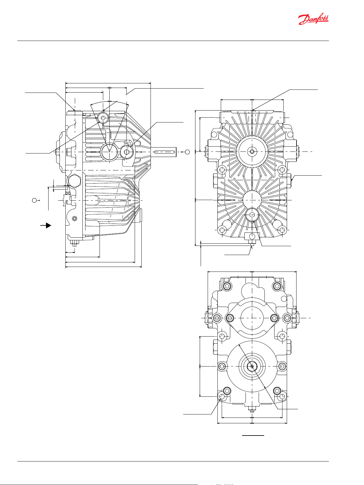
Installation Drawings
BDU-06S : Ports and Dimensions
.
©
Danfoss | November 2021 BC152886484098en-000207 | 35
Page 36

THRTHR
Left-hand side viewing from input shaft
(when pump located upside)
Option Code : L
Right-hand side viewing from input shaft
(when pump located upside)
Option Code : R
View B-B
B
B
10 ± 0.2
12
7.57.5
8181
-0.006
-0.024
13.5
+0.8
0
13.5
+0.8
0
Ø 5
+0.12
0
Ø 5
+0.12
0
P400235
17
4 ± 0.5
Involute Spline
Fillet Root Side Fit
SAE 1963 class 1
Pitch Diameter = 12.7
Pressure Angle = 30°
Number of Teeth = 16
Spline Pitch = 32/64
Involute Spline
JIS 15x13x1.0 class a
Tooth Profile Short Teeth
Module = 1.0
Pressure Angle = 20°
Number of Teeth = 13
Pitch Diameter = Ø13.0
Addendum Modification Coefficient = 0.8
30
0
-2.5
30
0
-2.5
20
0
-2.5
5
0
-2.5
Ø 14.8
Ø 15
Ø 15
0
-0.15
Ø 13.495
0
-0.15
P400236
Technical Information
BDU Series Hydrostatic Transmissions
Installation Drawings
Option Code R L
Input Rotation as Seen From A Direction CW CCW
Control Shaft Rotation a b a b
Output Rotation as Seen From B Direction CCW CW CW CCW
The tightening torque to install HST is 1569 to 2058 N·cm.
BDU-06S : Control Arm Location
BDU-06S : Motor Shaft
36 | © Danfoss | November 2021 BC152886484098en-000207
Page 37
103
20
20
3.5
6
a b
54.5 54.5
63
2.9
B
A
BDU-10L
Charge Pump
Suction Port
Reservoir Fitting
7/8- 14UNF-2B
SAE Straight THD.
O Ring Boss
(Both Sides)
67 ± 0.5
61.5 ± 0.4
21°
15°
+0.5
-2.5
21°
+0.5
-2.5
121
+1
-0.15
14 ± 0.2
27 ± 0.5
18 ± 0.3
97
+0.8
-0.5
Ø 47
+0.03
0
C
25 ± 0.5
66.75 ± 0.5
49 ± 0.5
66.5 ± 0.575 ± 0.0565 ± 0.8
77.4 ± 0.7
Bypass Valve Close
Bypass Valve
Open
30
Reservoir Fitting
7/8- 14UNF-2B
SAE Straight THD.
O Ring Boss
Reservoir Fitting
7/8- 14UNF-2B
SAE Straight THD.
O Ring Boss
BDU-10L
Charge Pump
Suction Port
7/8- 14UNF-2B
SAE Straight THD.
O Ring Boss
25 ± 0.5
68.5 ± 0.5 68.5 ± 0.5
Bypass Valve
View C
53 ± 0.18 53 ± 0.18
53 ± 0.18 53 ± 0.18
Ø 6
Ø 75
4- Ø 9 THR
Mounting Holes
0
-0.3
P400237
Technical Information
BDU Series Hydrostatic Transmissions
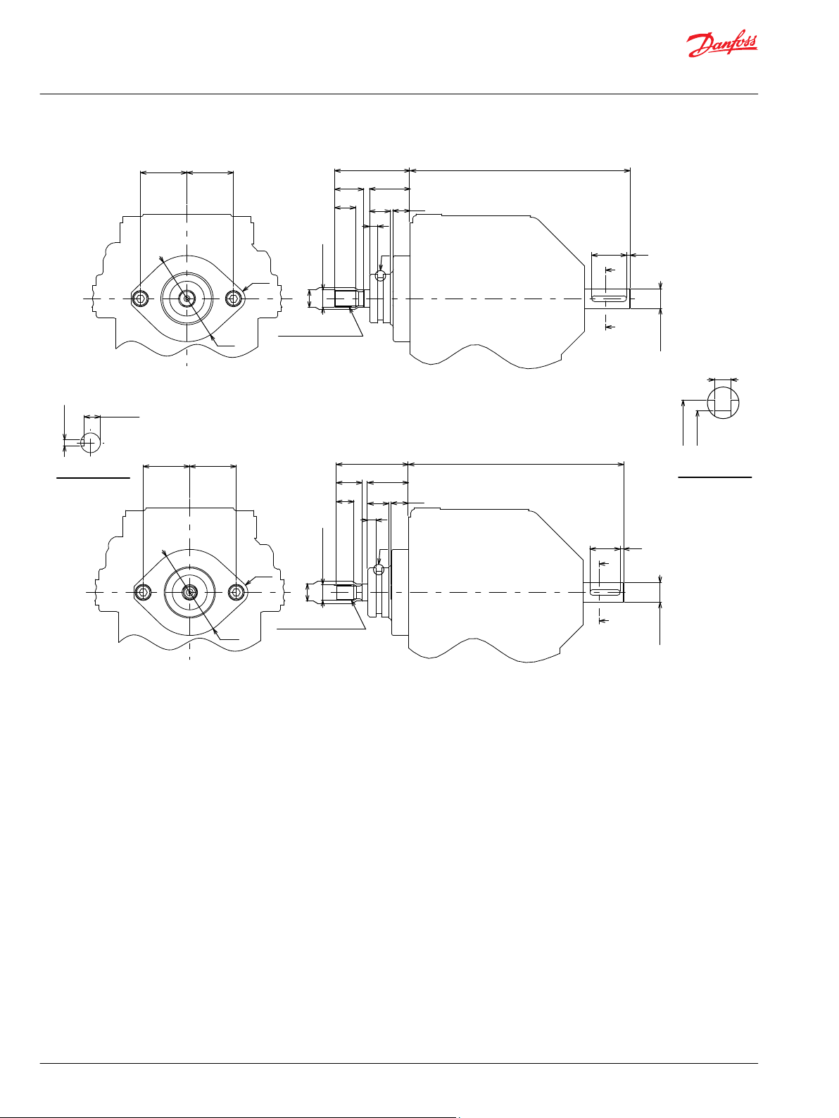
Installation Drawings
BDU-10S/10L : Ports and Dimensions
.
©
Danfoss | November 2021 BC152886484098en-000207 | 37
Page 38

7.5
84
7.5
84
E
E
E
E
Left-hand side viewing from input shaft
(when pump located upside)
Option Code : L
Right-hand side viewing from input shaft
(when pump located upside)
Option Code : R
13.5
+0.8
0
13.5
+0.8
0
5
+0.12
0
5
+0.12
0
Ø12
-0.006
-0.024
Ø12
-0.006
-0.024
10 ± 0.15
View E-E
P400238
Technical Information
BDU Series Hydrostatic Transmissions
Installation Drawings
Option Code R L
Input Rotation as Seen From A Direction CW CCW
Control Shaft Rotation a b a b
Output Rotation as Seen From B Direction CW CCW CCW CW
The tightening torque to install HST is 1569 to 2058 N·cm.
BDU-10S/10L : Control Arm Location
38 | © Danfoss | November 2021 BC152886484098en-000207
Page 39

17
4
Involute Spline
JIS 15x13x1.0 class a
Tooth Profile = Short Teeth
Module = 1.0
Pressure Angle = 20°
Number of Teeth = 13
Pitch Diameter = Ø13.0
Addendum Modification Coefficient = 0.8
Involute Spline
JIS 15x18x0.75 class a
Tooth Profile = Short Teeth
Module = 0.75
Pressure Angle = 20°
Number of Teeth = 18
Pitch Diameter = Ø13.5
Addendum Modification Coefficient = 0.5
Shaft : JIS 15x18x0.75
Option Code : K18
Shaft : JIS 15x13x1.0
Option Code : J13
Shaft : SAE 32/64-16T
Option Code : S16
Involute Spline
Fillet Root Side Fit
SAE 1963 class 1
Pitch Diameter = 12.7
Pressure Angle = 30°
Number of Teeth = Ø16
Spline Pitch = 32/64
4 ± 0.5
Ø14.8
Ø15
Ø15
0
-0.15
Ø13.495
Ø15
0
-0.15
Ø14.8
0
-0.15
30
0
-2.5
30
0
-2.5
24
0
-2.5
2.5
0
-2.5
5
0
-2.5
2.5
0
-2.5
P400239
Technical Information
BDU Series Hydrostatic Transmissions
Installation Drawings
BDU-10S/10L : Motor Shaft
©
Danfoss | November 2021 BC152886484098en-000207 | 39
Page 40

F
F
G
G
F
F
3030
8
8
18
8
30
F
F
3
9.6 ± 0.1
11.9 ± 0.1
Pump Sha ft : 15mm Straigh t Keyed
PTO Shaft : None
Charge Pump : None
Option Code : KB
Pump Sha ft : 15mm Straigh t Keyed
PTO Shaft : 12.7mm Straight Keyed
Charge Pump : None
Option Code : PB1
Pump Sha ft : 15mm Straigh t Keyed
PTO Shaft : Serration 12x23x0.5
Charge Pump : None
Option Code : PB2
Model Involute Serration
Module = 0.5
Pressure Angle = 45°
Number of Teeth = 23
Pitch Diameter = Ø11.5
(Effective Length of Spline)
165
+2
-1
165
+2
-1
165
+2
-1
24
+1
-2
30
+1
-2
22
+0.5
0
Ø15
0
-0.036
Ø15
0
-0.036
5
+0.03
0
5
+0.03
0
Ø12
0
-0.05
Ø15
0
-0.036
Ø12.7
0
-0.011
Section F-F
Section G-G
P400241
Technical Information
BDU Series Hydrostatic Transmissions
Installation Drawings
BDU-10S : Shaft Configuration
40 | © Danfoss | November 2021 BC152886484098en-000207
Page 41

H
H
I
I
30
R1
3
18
1.65
14
17
MAX.
MAX.
25
J
8
33 33
2-R7
H
H
30
16
8
10
33 33
2-R7
2-R7
33 33
8
30
J
25
H
H
2-R0.2
2-R0.5
1.65
1.4
1.7
R1
165
+2
-1
165
+2
-1
2.7
+0.23
0
165
+2
-1
50.1
+1
-2
55
+1
-2
22
+0.5
0
Ø15
0
-0.036
Ø15
0
-0.036
Ø31.8 ± 0.05
(Ø35)
Ø15
0
-0.036
5
+0.03
0
5
+0.03
0
Ø42Ø42
Ø35
-0.02
-0.05
Ø35
-0.02
-0.05
Ø12
0
-0.05
Ø12.6
0
-0.018
View J
11.9 ± 0.1
9.6 ± 0.1
Section H-H
Section I-I
Pump Sha ft : 15mm Straigh t Keyed
PTO Shaft : None
Charge Pump : 1.9 cc/rev
Option Code : KB1
Pump Sha ft : 15mm Straigh t Keyed
PTO Shaft : Serration 12x23x0.5
Charge Pump : 2.4 cc/rev
Option Code : PB4
Pump Sha ft : 15mm Straigh t Keyed
PTO Shaft : 12.7mm Straight Keyed
Charge Pump : 2.4 cc/rev
Option Code : PB3
Ø56
Ø58
Ø58
Ø41
(Effective Length of Spline)
Model Involute Serration
Module = 0.5
Pressure Angle = 45°
Number of Teeth = 23
Pitch Diameter = Ø11.5
P400240
Technical Information
BDU Series Hydrostatic Transmissions
Installation Drawings
BDU-10L : Shaft Configuration and Charge Pumps Displacement
©
Danfoss | November 2021 BC152886484098en-000207 | 41
Page 42
4.5
3.5
66
77.5
16
30
a b
Bypass Valve Close
Bypass Valve
Open
4
6161
7878
Bypass Valve
B
A
73
60
Ø 47
+0.03
0
C
150 ± 1.0
60 ± 0.7
122 ± 1.0
134 ± 1.5
Charge Pump
Suction Port
9/16- 18UNF-2B
SAE Straight THD.
O Ring Boss
In case of
External Filter
Charge Pump
Suction Port
9/16- 18UNF-2B
SAE Straight THD.
O Ring Boss
W/Option Filter
(Both Side)
Charge Pump
Suction Port
3/4- 16UNF-2B
SAE Straight THD.
O Ring Boss
In case of
External Filter
Drain Port
3/4- 16UNF-2B
SAE Straight THD.
O Ring Boss
(Both Side)
Drain Port
3/4- 16UNF-2B
SAE Straight THD.
O Ring Boss
Plug for C & HPRV
Only for BDU-21H
(Both Side)
Charge Pump Suction Port
In case of External Filter
View C
22°
+0° 40’
-2° 10’
22°
+0° 40’
-2° 10’
55 ± 0.555 ± 0.5
85 ± 0.07
53 ± 0.1853 ± 0.18
53 ± 0.18
53 ± 0.18
80.5
4- Ø 8.5 THR
Ø 90
Mounting Holes
P400243
Technical Information
BDU Series Hydrostatic Transmissions
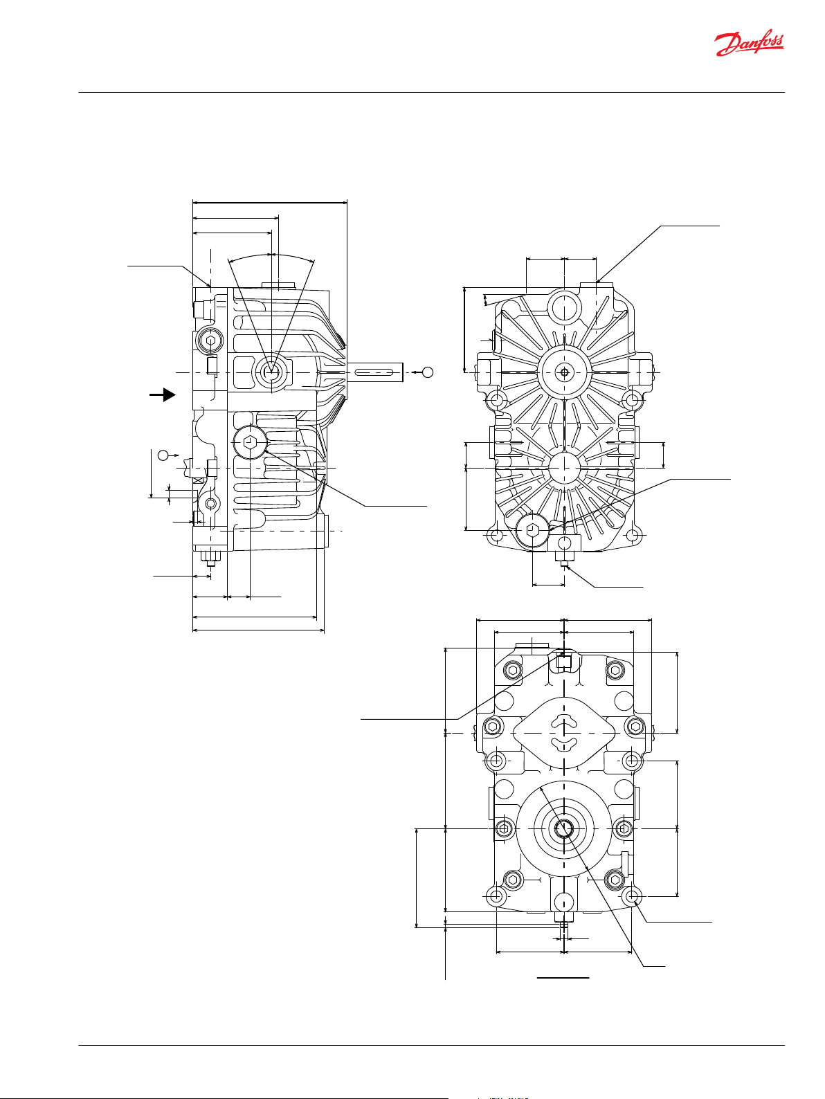
Installation Drawings
BDU-21L/21H : Ports and Dimensions
42 | © Danfoss | November 2021 BC152886484098en-000207
Page 43

9
9
97
E
E
E
E
97
Left-hand side viewing from input shaft
(when pump located upside)
Option Code : L
Right-hand side viewing from input shaft
(when pump located upside)
Option Code : R
P400242
15
+0.8
0
15
+0.8
0
Ø6
+0.12
0
Ø6
+0.12
0
Ø15
-0.006
-0.030
Ø15
-0.006
-0.030
12 ± 0.2
View E-E
Technical Information
BDU Series Hydrostatic Transmissions
Installation Drawings
Option Code R L
Input Rotation as Seen From A Direction CW CCW
Control Shaft Rotation a b a b
Output Rotation as Seen From B Direction CCW CW CW CCW
The tightening torque to install HST is 1569 to 2058 N·cm.
BDU-21L/21H : Control Arm Location
©
Danfoss | November 2021 BC152886484098en-000207 | 43
Page 44

Model Involute Spline
20x14x1.25 class a
Tooth Profile = Short Teeth
Module = 1.25
Pressure Angle = 20°
Number of Teeth = 14
Pitch Diameter = Ø17.5
Addendum Modification Coefficient = 0.8
Model Involute Spline
Fillet Root Side Fit
SAE 1963 class 1
Pressure Angle = 30°
Number of Teeth = 22
Pitch Diameter = Ø17.643
Spline Pitch = 32/64
Model Involute Spline
20x18x1.0 class a
Tooth Profile = Short Teeth
Module = 1.0
Pressure Angle = 20°
Number of Teeth = 18
Pitch Diameter = Ø18.0
Addendum Modification Coefficient = 0.8
21.5
0
-0.5
16
2
32
32
5
4
37
Shaft : JIS 20x18x1.0
Option Code : J18
Shaft : JIS 20x14x1.25
Option Code : J14
Shaft : SAE 32/64-22T
Option Code : S22
Ø20
Ø19.75
0
-0.15
Ø20
0
-0.1
Ø18.263
0
-0.15
Ø20
Ø19.8
(Effective Length of Spline)
P400244
Technical Information
BDU Series Hydrostatic Transmissions
Installation Drawings
BDU-21L/21H : Motor Shaft
44 | © Danfoss | November 2021 BC152886484098en-000207
Page 45

7
R10
40 40
18
G
F
F
25 ± 0.25
15
26
3
185 ± 2.0
13.9 ± 0.1
3
36
F
F
16
40 40
R7
10
R7
40 40
3
36
F
F
18
12
Ø17
0
-0.036
Ø17
0
-0.036
Ø40
60
°
Ø72
Ø40
Ø72
Ø74
Pump Shaft : 17mm Straight Keyed (Key Length 36mm)
PTO Shaft : None
Charge Pump : 3.1cc/rev (for 21H)
Option Code : KC2
Pump Shaft : 17mm Straight Keyed (Key Length 36mm)
PTO Shaft : None
Charge Pump : 2.1cc/rev (for 21L)
Option Code : KC1
Pump Shaft : 17mm Straight Keyed (Key Length 26mm)
PTO Shaft : Involute Spline JIS 15x13x1.0
Charge Pump : 2.1cc/rev (for 21L), 3.1 cc/rev (for 21H)
Option Code : PC1 (2.1cc/rev), PC2(3.1 cc/rev)
195 ± 2.0
195 ± 2.0
65 ± 2.0
35
0
-0.5
18
+0.5
0
Ø15
Ø14.8
0
-0.1
Ø17
0
-0.036
5
+0.03
0
Ø42
Ø36
0
-0.039
4.7
+0.25
0
Model Involute Spline
JIS 15x13x1.0 Class a
Tooth Profile = Short Teeth
Module = 1.0
Pressure Angle = 20°
Number of Teeth = 13
Pitch Diameter = Ø13.0
Addendum Modification
Coefficient = 0.8
View G-G
Section F-F
P400245
Technical Information
BDU Series Hydrostatic Transmissions
Installation Drawings
BDU-21L/21H : Shaft Configuration and Charge Pump Displacement
©
Danfoss | November 2021 BC152886484098en-000207 | 45
Page 46
189 ± 2.0
3
30
65 ± 2.0
25 ± 0.25
22
18
15
F
F
40 40
R10
7
G
G
7
R10
40 40
F
F
15
62± 2.0
26
3
185 ± 2.0
13.9 ± 0.1
18
15
5
+0.03
0
Section F-F
Ø42
Ø36
0
-0.039
4.7
+0.25
0
View G-G
Ø74
Ø74
Pump Shaft : 17mm Straight Keyed (Key Length 30mm)
PTO Shaft : Involute Spline JIS 15x13x1.0
Charge Pump : 2.1cc/rev (for 21L), 3.1 cc/rev (for 21H)
Option Code : PC3 (2.1 cc/rev), PC4(3.1 cc/rev)
Pump Shaft : 17mm Straight Keyed (Key Length 26mm)
PTO Shaft : Involute Spline SAE 32/64-16T
Charge Pump : 2.1cc/rev (for 21L), 3.1 cc/rev (for 21H)
Option Code : PC5 (2.1 cc/rev), PC6(3.1 cc/rev)
Model Involute Spline
JIS 15x13x1.0 Class a
Tooth Profile = Short Teeth
Module = 1.0
Pressure Angle = 20°
Number of Teeth = 13
Pitch Diameter = Ø13.0
Addendum Modification
Coefficient = 0.8
Model Involute Spline
Fillet Root Side Fit
SAE 1963 Class 1
Module = 1.0
Pressure Angle = 30°
Number of Teeth = 16
Pitch Diameter = Ø12.7
Spline Pitch = 32/64
35
0
-0.5
35
0
-0.5
18
+0.5
0
+0.5
0
Ø15
Ø14.8
0
-0.1
Ø15
Ø13.495
0
-0.15
Ø17
0
-0.036
Ø17
0
-0.036
P400247
Technical Information
BDU Series Hydrostatic Transmissions
Installation Drawings
46 | © Danfoss | November 2021 BC152886484098en-000207
Page 47

CCW
A
2.5
23
18.5
31.8
Rotation
(4 Places) Ø7.1
L
Ø45.7
Ø177.8
Ø88.9
Ø24
Wind
+0.4
-0.6
Ø84
0
-1.5
P400248
Technical Information
BDU Series Hydrostatic Transmissions
Installation Drawings
Optional Fan
©
Danfoss | November 2021 BC152886484098en-000207 | 47
Page 48

Danfoss
Power Solutions GmbH & Co. OHG
Krokamp 35
D-24539 Neumünster, Germany
Phone: +49 4321 871 0
Danfoss
Power Solutions ApS
Nordborgvej 81
DK-6430 Nordborg, Denmark
Phone: +45 7488 2222
Danfoss
Power Solutions (US) Company
2800 East 13th Street
Ames, IA 50010, USA
Phone: +1 515 239 6000
Danfoss
Power Solutions Trading
(Shanghai) Co., Ltd.
Building #22, No. 1000 Jin Hai Rd
Jin Qiao, Pudong New District
Shanghai, China 201206
Phone: +86 21 2080 6201
Products we offer:
Hydro-Gear
www.hydro-gear.com
Daikin-Sauer-Danfoss
www.daikin-sauer-danfoss.com
Cartridge valves
•
DCV directional control
•
valves
Electric converters
•
Electric machines
•
Electric motors
•
Gear motors
•
Gear pumps
•
Hydraulic integrated
•
circuits (HICs)
Hydrostatic motors
•
Hydrostatic pumps
•
Orbital motors
•
PLUS+1® controllers
•
PLUS+1® displays
•
PLUS+1® joysticks and
•
pedals
PLUS+1® operator
•
interfaces
PLUS+1® sensors
•
PLUS+1® software
•
PLUS+1® software services,
•
support and training
Position controls and
•
sensors
PVG proportional valves
•
Steering components and
•
systems
Telematics
•
Danfoss Power Solutions is a global manufacturer and supplier of high-quality hydraulic and
electric components. We specialize in providing state-of-the-art technology and solutions
that excel in the harsh operating conditions of the mobile off-highway market as well as the
marine sector. Building on our extensive applications expertise, we work closely with you to
ensure exceptional performance for a broad range of applications. We help you and other
customers around the world speed up system development, reduce costs and bring vehicles
and vessels to market faster.
Danfoss Power Solutions – your strongest partner in mobile hydraulics and mobile
electrification.
Go to www.danfoss.com for further product information.
We offer you expert worldwide support for ensuring the best possible solutions for
outstanding performance. And with an extensive network of Global Service Partners, we also
provide you with comprehensive global service for all of our components.
Local address:
Danfoss can accept no responsibility for possible errors in catalogues, brochures and other printed material. Danfoss reserves the right to alter its products without notice. This also applies to products
already on order provided that such alterations can be made without subsequent changes being necessary in specifications already agreed.
All trademarks in this material are property of the respective companies. Danfoss and the Danfoss logotype are trademarks of Danfoss A/S. All rights reserved.
©
Danfoss | November 2021 BC152886484098en-000207
 Loading...