Danfoss BD Controller 101N07 User guide

MAKING MODERN LIVING POSSIBLE

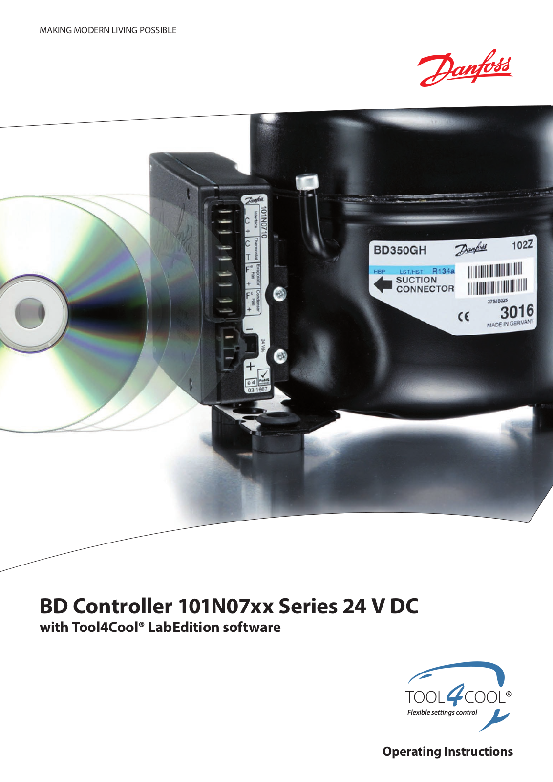
BD Controller 101N07xx Series 24 V DC

with Tool4Cool® LabEdition software

Operating Instructions

Operating Instructions

BD Controller 101N07xx Series 24 V DC


2

DEHC.PS.100.I.02

Operating Instructions

BD Controller 101N07xx Series 24 V DC


1.0Introduction

1.1

Applications..................................................................................................................................

5

1.2

Capability ......................................................................................................................................

5

1.3

Functions .......................................................................................................................................

5

1.4

Programming Interface ............................................................................................................

5

2.0Installation

2.1

Checklist ........................................................................................................................................

7

2.2

Connect cables ............................................................................................................................

8

2.3

Install and configure software ...............................................................................................

9

3.0Operation

3.1

User interface .............................................................................................................................

11

3.2

Operation ....................................................................................................................................

11

4.0Parameters


4.1 Parameter Overview................................................................................................................

13


4.2 Description of Parameters ....................................................................................................

15


4.2.1

Main Functions............................................................................................................

15


4.2.2

Battery protection......................................................................................................

15


4.2.3

Compressorn ...............................................................................................................

16


4.2.4

Condenser fan.............................................................................................................

17


4.2.5

Evaporator fan ............................................................................................................

17


4.2.6

Thermostat....................................................................................................................

18


4.2.7

ECO function................................................................................................................

19


4.2.8

Compressor safety......................................................................................................

20


4.2.9

Communication..........................................................................................................

20


4.2.10

Product information.................................................................................................

21


4.2.11

Customer register .....................................................................................................

21


4.2.12

Actual error...................................................................................................................

21


4.2.13

Inverter Temperature (PCB)....................................................................................

22

5.0

Ordering

...........................................................................................................................................

25

6.0

More Information ......................................................................................................................

27

DEHC.PS.100.I1.02

3

4

TOOL4COOL®

BD Controller 1. Introduction

101N07xx Series

24 V DC

1.1 Applications

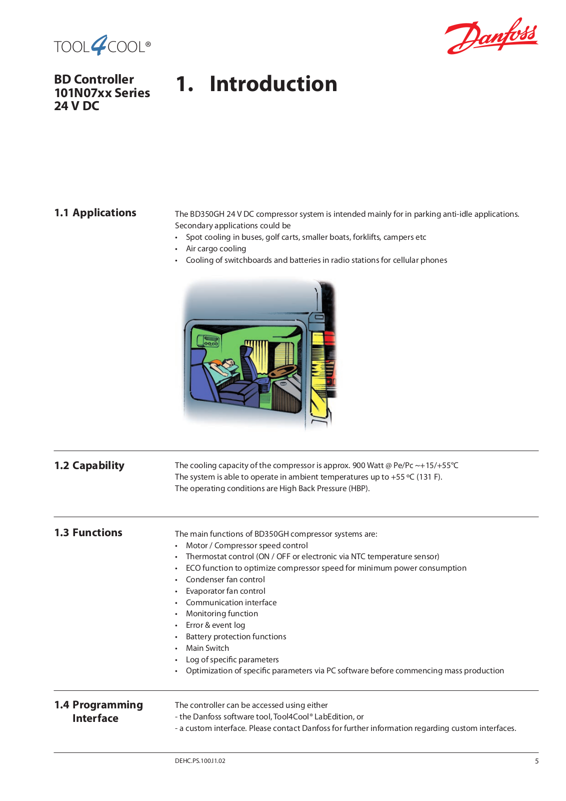
The BD350GH 24 V DC compressor system is intended mainly for in parking anti-idle applications. Secondary applications could be

Spot cooling in buses, golf carts, smaller boats, forklifts, campers etc

Air cargo cooling

Cooling of switchboards and batteries in radio stations for cellular phones

1.2 Capability

The cooling capacity of the compressor is approx. 900 Watt @ Pe/Pc ~+15/+55°C The system is able to operate in ambient temperatures up to +55 ºC (131 F). The operating conditions are High Back Pressure (HBP).

1.3 Functions

The main functions of BD350GH compressor systems are:

Motor / Compressor speed control

Thermostat control (ON / OFF or electronic via NTC temperature sensor)

ECO function to optimize compressor speed for minimum power consumption

Condenser fan control

Evaporator fan control

Communication interface

Monitoring function

Error & event log

Battery protection functions

Main Switch

Log of specific parameters

Optimization of specific parameters via PC software before commencing mass production

1.4Programming Interface

The controller can be accessed using either

-the Danfoss software tool,Tool4Cool® LabEdition, or

-a custom interface. Please contact Danfoss for further information regarding custom interfaces.

DEHC.PS.100.I1.02

5

6

TOOL4COOL®

BD Controller 2. Installation

101N07xx Series

24 V DC

2.1 Checklist

Installation involves the following steps:

Checklist

Cable connection

Software installation and confi guration

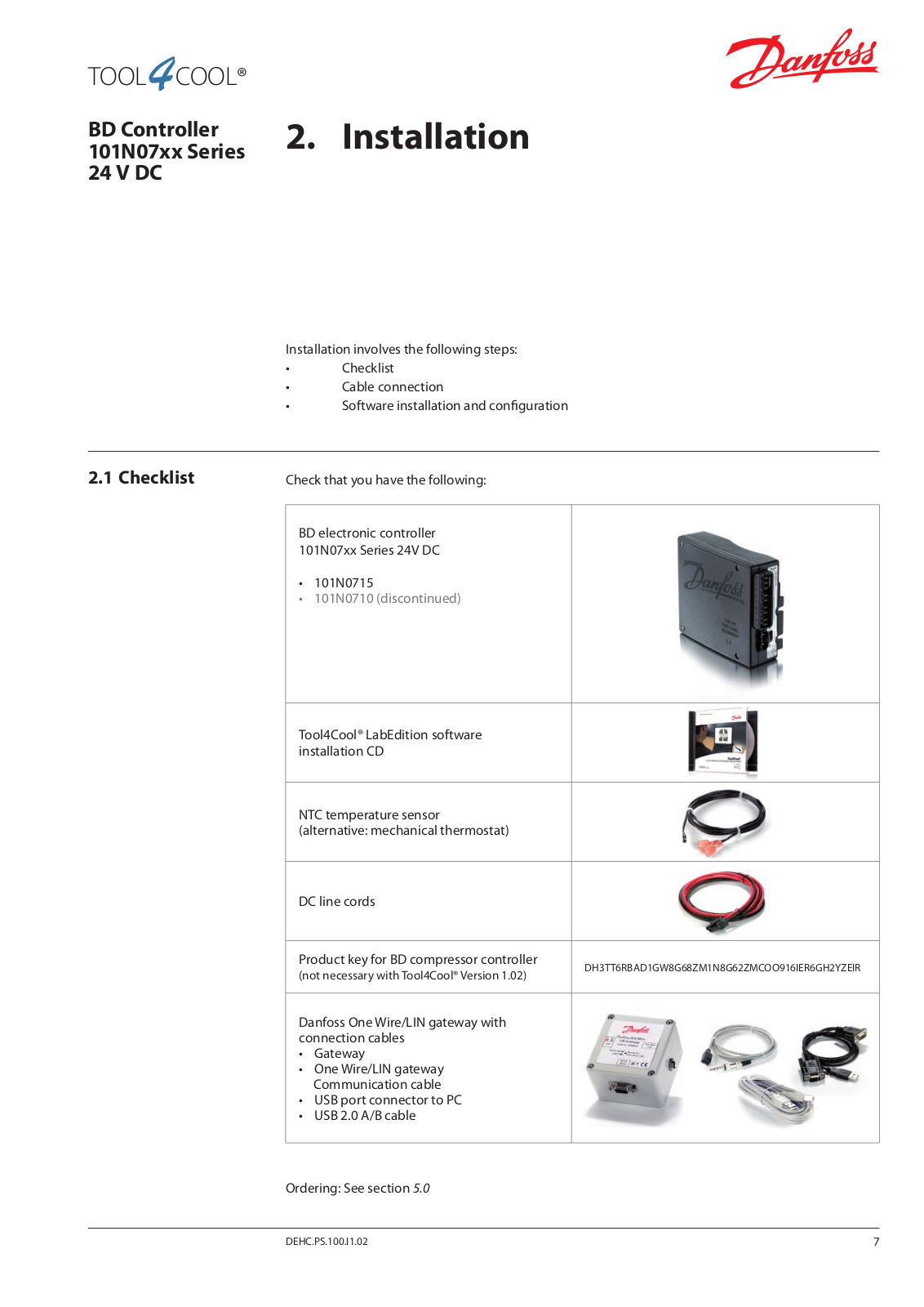
Check that you have the following:

BD electronic controller 101N07xx Series 24V DC

101N0715

101N0710 (discontinued)

Tool4Cool® LabEdition software


installation CD


NTC temperature sensor


(alternative: mechanical thermostat)


DC line cords


Product key for BD compressor controller

DH3TT6RBAD1GW8G68ZM1N8G62ZMCOO916IER6GH2YZEIR

(not necessary with Tool4Cool®Version 1.02)


Danfoss One Wire/LIN gateway with connection cables

Gateway

One Wire/LIN gateway Communication cable

USB port connector to PC

USB 2.0 A/B cable

Ordering: See section 5.0

DEHC.PS.100.I1.02

7

Danfoss BD Controller 101N07 User guide

Operating Instructions BD Controller 101N07xx Series 24 V DC

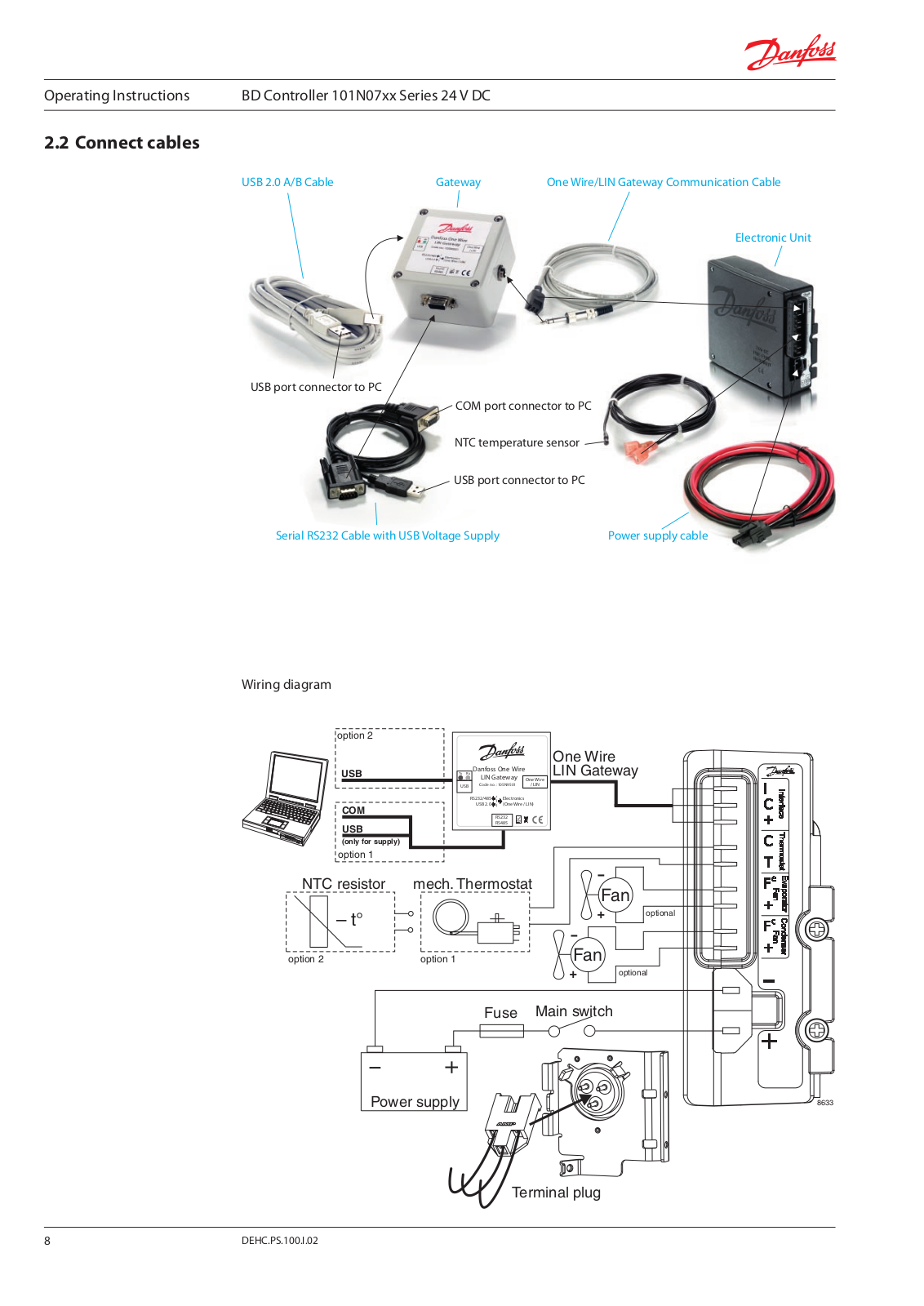
2.2 Connect cables

USB 2.0 A/B Cable

Gateway

One Wire/LIN Gateway Communication Cable


Electronic Unit

USB port connector to PC

COM port connector to PC

NTC temperature sensor

USB port connector to PC

Serial RS232 Cable with USB Voltage Supply

Power supply cable

Wiring diagram

option 2

USB

COM

USB

(only for supply) option 1

NTC resistor

– t°

option 2


One Wire

Tx Rx

Danfoss One Wire

LIN Gateway


LIN Gateway


One Wire

USB

Code n o.: 105N9501

/ LIN


RS232/485 Electronics


USB 2.0 (One Wire / LIN)


RS232


RS485


mech. Thermostat

-


Fan


+

optional


-


option 1

Fan


+

optional

Fuse

Main switch


Power supply

8633

Terminal plug

8

DEHC.PS.100.I.02

Operating Instructions

BD Controller 101N07xx Series 24 V DC


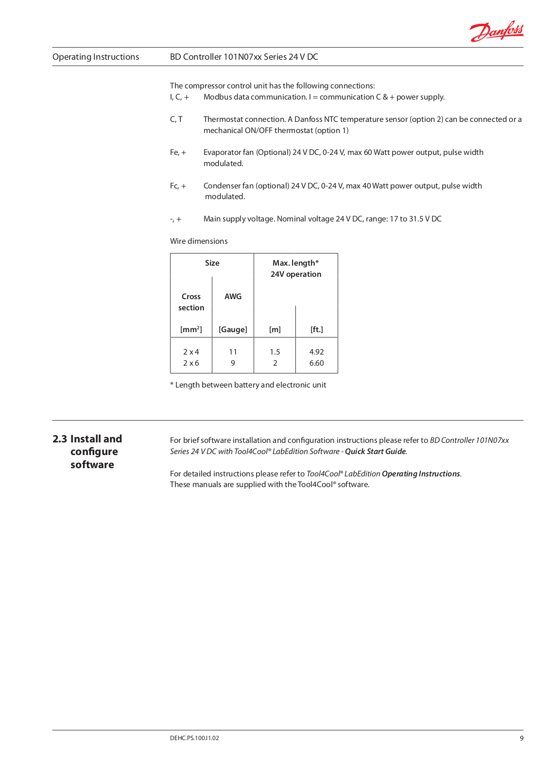
The compressor control unit has the following connections:

I, C, + Modbus data communication. I = communication C & + power supply.

C,T Thermostat connection. A Danfoss NTC temperature sensor (option 2) can be connected or a mechanical ON/OFF thermostat (option 1)

Fe, + Evaporator fan (Optional) 24V DC, 0-24V, max 60Watt power output, pulse width modulated.

Fc, + Condenser fan (optional) 24V DC, 0-24V, max 40Watt power output, pulse width modulated.

-, +

Main supply voltage. Nominal voltage 24V DC, range: 17 to 31.5V DC

Wire dimensions


Size

Max. length*


Cross


AWG

24V operation


section


[mm2]


[Gauge]

[m]

[ft.]


2 x 4


11

1.5

4.92


2 x 6


9

2

6.60


* Length between battery and electronic unit

2.3Install and configure software

For brief software installation and configuration instructions please refer to BD Controller 101N07xx Series 24 V DC with Tool4Cool® LabEdition Software - Quick Start Guide.

For detailed instructions please refer to Tool4Cool® LabEdition Operating Instructions.

These manuals are supplied with theTool4Cool® software.

DEHC.PS.100.I1.02

9

Loading...
+ 19 hidden pages