

Page 1
INSTRUCTIONS
8238-16
8527-2
230V AC
or
300V DC
BD150F
COMPRESSOR INVERTER xxV
Type xx – BD 150
Pure sine wave
Code no 105N09xx
Powe
r
Low battery
xxVDC
+
-
Remote
12 / 24V DC
+
–
Battery
Inverter for BD150F Compressors
Type 12 – BD150 code no 105N0912
Type 24 – BD150 code no 105N0924
12/24V DC - 230V AC
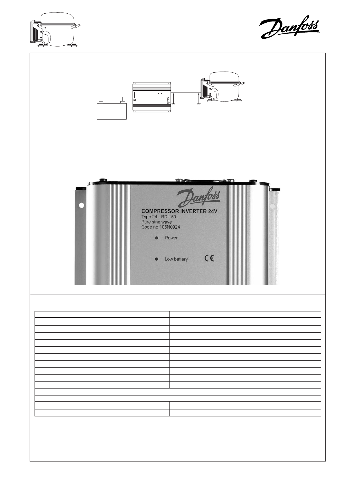
System conguration
Identication
The identication of the code no is shown on the photo below.
• 12V DC units: 105N0912
• 24V DC units: 105N0924
Technical data
Electrical specications
Input voltage 12V DC version 12V DC nominal, range 10-15V DC
Input voltage 24V DC version 24V DC nominal, range 20-30V DC
Output voltage 230 V AC ±3%
Frequency 50 Hz
Output wave form Pure sine-wave
Continuous output power 300 W
Standby consumption 5 mW
No load power consumption 12V DC version 8.5 W
No load power consumption 24V DC version 12 W
Efciency at full load > 90 %
Environmental specications
Ambient temperature during operation –20°C to + 55°C
Cooling Static air cooling
CI.46.F1.02 10-2003
Page 2
3
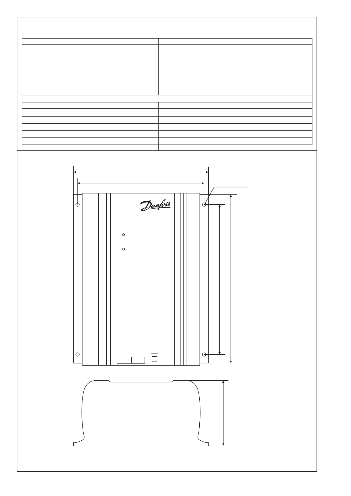
Technical data (continued)
98 mm (3.86")
8526
COMPRESSOR INVERTER 12V
Type 12 – BD 150
Pure sine wave
Code no 105N0912
Powe
r
Low battery
205 mm
(8.07")
250 mm (9.04")
190 mm
(7.48")
215 mm
(8.46")
Ø
")
5 mm
(0.2
12VDC
+
-
Remote
Mechanical specications
Housing Anodized extruded aluminum
Weight 4.5 kg ~ 10 lbs
AC outlet 3-pole female IEC socket
Housing dimensions in mm (L x W X H) 250 x 205 x 98)
Mounting Horizontal or vertical
Alarm indication Overload/High temp./Short circuit/Low battery
Enclosure IP 21
Standards
CE marking EMC directive 89/336/EEC
Automotive directive 95/54/EC
Emission EN 50081-1
Immunity EN 50082-2
Safety IEC 950
Dimensions
2
Page 3

Installation
It is recommended to install the inverter in a dry and dust free environment.
Place the inverter as close as possible to the battery, in order to keep the lengths of the cables between battery and inverter as short
as possible.
Never use the inverter in environments with presence of dust or explosive gases.
The inverter can be mounted on a wall or at mounted.
Optimum cooling is obtained in a vertical position.
Cables
The cables between the battery and the inverter must be sized
according to the table below.
Good EMC properties are obtained in the following way:
Place the cables in a metal rail. The metal offers resistance
against interference currents. The battery cables should be
The wiring of the cables is inuencing the EMC behavior of the
system, in which the inverter is a component. This is due to the
fact that the cables are receiver and transmitter antennas of
placed close to each other to reduce looping area. Cables from
different groups should not be twisted but be placed parallel
with each other.
radio frequency electromagnetic interference.
Size Max. length between battery Max. length between battery
and inverter. 12V operation and inverter. 24V operation
AWG Gauge
mm
6 16 8 2.5 16 5
4 25 13 4 26 8
Cross section
2
Foot Meter Foot Meter
Mounting of the cables
• Check that the battery voltage matches the inverter DC input
voltage.
• Check that the inverter is switched off.
• Connect the cables to the inverter.
• Check that the cables are well tightened.
• Make sure that the battery poles are clean, and that there is a
good electrical contact.
• Connect the selected cables to the battery.
230V AC
Ensure that the inverter is switched off before connecting an AC
cable to the inverter.
Mount a 3-pole male connector into the 230V AC socket on the
inverter.
Remote input
The remote input is used to turn the inverter ON/OFF remotely
e.g. through a cars ignition system.
The power consumption of BD150F is usually so big that a
standard battery car would be drained very fast if the engine is
not running.
Monitoring
The inverter is equipped with two LED.
The power LED
Constant light: The inverter is in operation mode.
1 ash: Overload. The inverter is overloaded.
2 ashes: High temperature. The inverter is too hot inside,
and will enter standby mode. When the inverter
has cooled down it will restart automatically.
3 ashes: Short circuit. Switch of the inverter and load.
Check all equipment and nd out what caused
the short circuit, before the inverter is restarted.
4 ashes: Battery can not handle high peak power.
Wrong or defect battery.
Note!
Do not interchange the battery cables. It will result in instantaneous damage of the inverter.
The inverter is protected against overload and short circuit. It is
not necessary to mount a fuse at the output of the inverter.
Note!
The remote switch is positive. Do not touch the housing of the
inverter, with the remote switch terminal, it will damage the
switch.
The low battery LED
Constant light: The voltage is below 10V DC on a 12V DC
version or below 20V DC on a 24 V DC version.
Check the condition of the battery, check if there
are loose connections.
Eventually charge the battery.
3
 Loading...