

Data sheet
TR(TW)700
Temperature controller (NC) (PN 25)
AVT / VGU - external thread
AVT / VGUF - flange
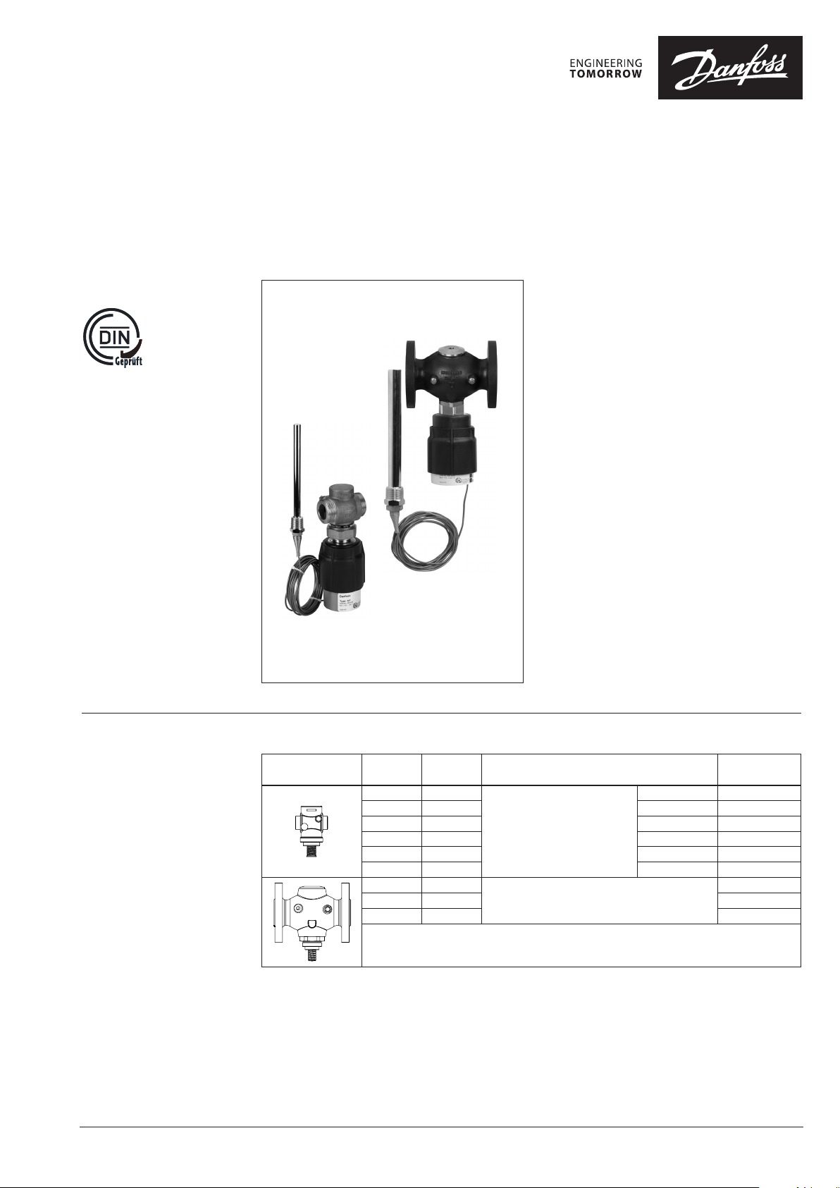
Description
AVT / VGU
AVT / VGUF
The AVT / VGU(F) is a self-acting proportional
temperature controller developed primarily for
cooling applications.
Controller opens on rising temperature.
The controller has a control valve VGU(F),
thermostatic actuator and handle for
temperature setting. Thermostatic actuator
consist of bellows, capillary tube and sensor.
The temperature controller is type-tested
according to EN 14597.
Main data:
• DN 15-50
• kVS 4.0 -25 m3/h
• PN 25
• Setting ranges:
−10 … 40 °C / 20 … 70 °C / 40 … 9 0 °C /
60 … 110 °C
• Temperature:
- Circ. water / glycolic water up to 30%:
2 … 150 °C
• Connections:
- Ext. thread
(weld-on, thread and flange tailpieces)
- Flange
• Flow and return mounting.
Ordering
Example:
Temperature controller for cooling,
DN 15; kVS 4.0 ; PN 25; setting range
−10 … 40 °C; T
- 1× VGU DN 15 valve
Code No: 065 B0791
- 1× AVT thermostatic actuator,
−10 … 40 °C
Code No: 065-0596
Option:
- 1× Weld-on tailpieces
Code No: 003H6908
150 °C; ext. thread
max
© Danfoss | 2017.08
VGU, VGUF valve
Picture
DN k
(mm) (m3/h)
15 4.0
20 6.3 G 1 A 065B0792
25 8.0 G 1¼ A 065B0793
32 12.5 G 1¾ A 065B0794
40 16 G 2 A 065B0795
50 20 G 2½ A 065B 0796
32 12.5
40 20 065B0798
50 25 065B0799
VS
Cylindrical external thread acc. to
ISO 228/1
Flanges PN 25, acc. to EN 1092-2
Connection Code No.
G ¾ A 065B0791
065B0797
VD.JK.B6.02 | 1
Data sheet Temperature controller AVT / VGU(F) (PN 25)
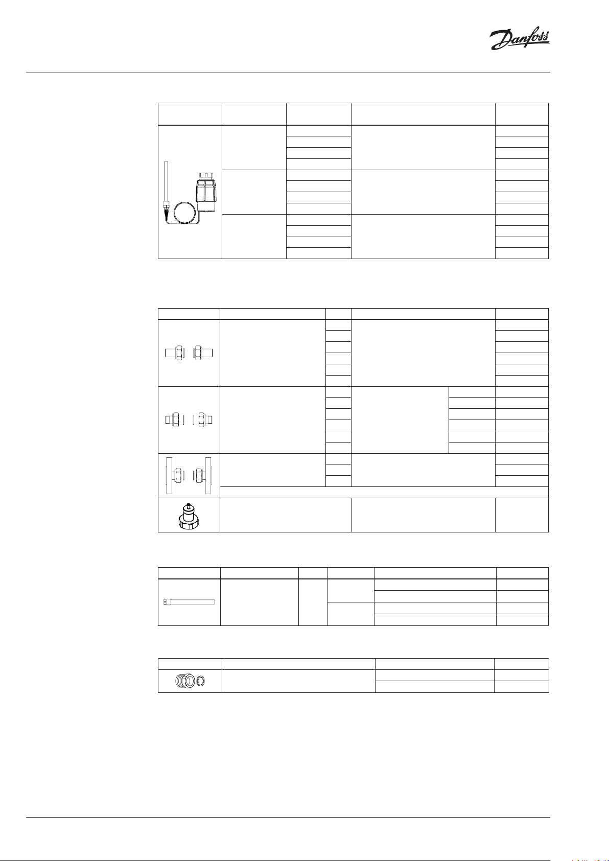
Ordering (continuous)
AVT thermostatic actuator
Picture For valves
Setting range
(°C)
−10 … +40
DN 15-2 5
20 … 70 065-0597
40 … 90 065-0598
60 … 110 065-0599
−10 … +40
DN 32-50
20 … 70 065-0601
40 … 90 065-0602
60 … 110 065-0603
10 … 45
DN 15-50
35 … 70 065-0605
60 … 100 065-0606
85 … 12 5 065-0607
1)
conic male threa d EN 10226
2)
without imme rsion pocket
3)
setting rang e is for aprox. 5-10 °C higher as stated (see Adjust ment diagram section)
Temperature sensor with brass immersion
pocket, length, connection
170 mm, R ½
210 mm, R ¾
255 mm, R ¾
1)
1)
1) 2) 3)
Accessories for valves
Picture Type designation DN Connection Code No.
15
20 003H6909
Weld-on tailpieces
External thread tailpieces
Flange tailpieces
25 00 3H6910
32 0 03 H69 11
-
40 00 3H6912
50 0 03H6 913
15
R ½ 003H6902
20 R ¾ 003H6903
25 R 1 003H6904
Conical ex t. thread acc. to EN
32 R 1¼ 003H6905
10226-1
40 R 1½ 065F6061
50 R 2 065F6062
15
20 003H6 916
Flanges PN 25, acc. to EN 1092-2
25 0 03H6 917
Code No.
065-0596
065-0600
065-0604
003H6908
003H6 915
1)
Adapter
1)
Adapter for VGU(F) comb inations with electrical a ctuators type AMV(E) 20, 23, 30, 33.
M45 × 1.5 mm / M30 × 1. 5 mm 003H6928
Accessories for thermostats
Picture Type designation PN For valves Material Code No.
DN 15-2 5
Immersion pocket 25
DN 32-50
1)
Not for AVT the rmostatic actuator code numb er: 065-0604, 065-0605, 065 -0606, 065 -0607
Stainless steel, mat. No. 1.4571 065- 4415
Stainless steel, mat. No. 1.4435 06 5- 4417
Brass 06 5-4 414
Brass 065 -4416
Service kits
Picture Type designation for sensors Code No.
Housing of sensor stuffing box
AVT R ½ 065- 4420
AVT R ¾ 065-4 421
1)
1)
1)
1)
2 | VD.JK.B6.02
© Danfoss | 2017.08
Data sheet Temperature controller AVT / VGU(F) (PN 25)
Technical data
Valves
Nominal diameter DN 15 20 25 32 40 50
kVS value m3/h 4.0 6.3 8.0 12.5 20 25
Stroke mm 5
Control ratio >1:50
Control characteristic linear
Cavitation factor z ≥ 0.6 ≥ 0.55 ≥ 0.5
Leakage acc. to standard IEC 534 % of k
Nominal pressure PN 25
Max. differential pressure bar 20 16
Medium Circulation water / glycolic water up to 30%
Medium pH Min. 7, max. 10
Medium temperature °C 2 … 150
valve External thread External thread and flange
Connections
Materials
Valve body Red bronze CuSn5ZnPb (Rg5)
Valve seat Stainless steel, mat. No. 1.4571
Valve cone Dezincing free brass CuZn36Pb2As
Sealing EPDM
Pressure relieve system Piston
tailpieces
VS
≤ 0.02 ≤ 0.05
Weld-on and external thread
Flange -
Ductile iron
EN-GJS-400-18-LT (GGG 40.3)
Thermostatic actuator
Setting range X
Time constant T acc. to EN 14597 s max. 50 (170 mm, 210 mm), max. 30 (255 mm)
Gain K
Max. adm. temperature at sensor 50 °C above maximum setpoint
Max. amb. temperature at sensor
Nominal pressure sensor
Nominal pressure immersion pocket
Capillary tube length 5 m (170 mm, 210 mm), 4 m (255 mm)
Materials
Temperature sensor Cooper
Immersion pocket
Handle for temp. setting Polyamide, glass fiber-reinforced
Scale carrier Polyamide
1)
for sensor 170 and 210 mm
s
s
1)
Ms design Brass, nickel-plated
Stainless steel design Mat. No. 1.4571 (170 mm), mat. No. 1.4435 (210 mm)
°C
mm / °K
°C
PN 25
−10 … 40 / 2 0 … 70 / 40 … 9 0 / 60 … 11 0
10 … 45 / 35 … 70 / 60 … 100 / 85 … 125
0.2 (170 mm), 0.3 (210 mm), 0.7 (255 mm)
0 … 70
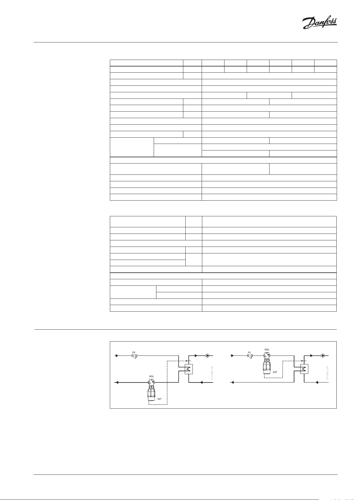
Application principles
© Danfoss | 2017.08
VD.JK.B6.02 | 3

Data sheet Temperature controller AVT / VGU(F) (PN 25)
Installation positions
Temperature controller
Temperature controller AVT / VGU(F) can be
installed in any position.
Temperature sensor
The place of installation must be chosen in a way
that the temperature of the medium is directly
taken without any delay. Avoid overheating of
temperature sensor. The temperature sensor
must be immersed into the medium in its full
length.
Temperature s
ensors 170 mm R ½ and 210 mm R ¾
- The temperature sensor may be installed in
any position.
Temperature sensor 255 mm R ¾
- The temperature sensor must be installed as
shown on the picture.
Pressure temperature
diagram
4 | VD.JK.B6.02
EN-GJS- 400-18 -LT (GGG 40.3) PN 25
CuSn5ZnPb (Rg5) PN 25
Maximum allowed operating pressure as a function of medium temperature (according to EN 1092-2 and EN 1092-3).
© Danfoss | 2017.08

Data sheet Temperature controller AVT / VGU(F) (PN 25)
×
×
Valve sizing
Given data:
P
= 10 kW
max
t = 6 K
pv = 0.15 bar
P
- cooling power (kW)
max
t - temperature difference (K)
pv - differential pressure across the valve
Maximum flow Q
calculated according to formula:
Q
Q
max
=
max
= 1.43 m3/h
max
(m3/h) through the valve is
max
86.0P
=
t
∆
86.010
6
kv value is calculated according to formula:
max
1.43
==
0.15
V
Q
k
v
Δp
kv = 3.7 m3/h
Chosen kVS = 4.0 m3/h
or
read from the sizing diagram by taking a line
through Q scale (1.43 m3/h) and pv scale
(0.15 bar) to intersect kv-scale at 3.7 m3/h
Chosen kVS = 4.0 m3/h
Solution:
The example selects ext. thread valve VGU DN 15,
kVS value 4.0 .
© Danfoss | 2017.08
VD.JK.B6.02 | 5

Data sheet Temperature controller AVT / VGU(F) (PN 25)
Design
1. Valve VGU(F)
2. Valve insert
3. Pressure relieved valve cone
4. Valve stem
5. Union nut
6. Thermostatic actuator AVT
7. Thermostat stem
8. Bellows
9. Setting spring for
temperature control
10. Handle for temperature
setting, prepared for sealing
11. Scale carrier
12. Capillary tube
13. Flexible protected pipe
(only at AVT 255 mm)
14. Temperature sensor
15. Immersion pocket
16. Sensor stuffing box
17. Housing of sensor stuffing
box
Function
AV T 170
AVT 255
AV T 210
Medium temperature changes cause pressure
changes in temperature sensor. Resulting
pressure is being transferred through the
capillary tube to the bellows. Bellows moves
thermostat stem and opens or closes the valve.
By increasing of medium temperature valve cone
moves away the seat (valve opens by decreasing
of medium temperature valve cone moves
towards from the seat (valve closes).
Handle for temperature setting can be sealed.
Settings
Adjustment diagram
Temperature setting
Temperature setting is being done by the
adjustment of the setting spring for temperature
control.
Temperature setting
Relation between scale numbers 1-5 and closing
temperature.
Note: The va lues given are approximate
AVT Thermostat ... 170 mm, 210 mm
AVT Thermostat ... 255 mm
The adjustment can be done by means of handle
for temperature setting and/or temperature
indicators.
6 | VD.JK.B6.02
© Danfoss | 2017.08

Data sheet Temperature controller AVT / VGU(F) (PN 25)
Dimensions
L
1
L
2
H
H
3
150
H
L L1H H1H2H
DN
mm
15 65 - 180 - 34 -
20 70 - 180 - 34 -
25 75 - 180 - 37 -
32 100 180 221 221 63 70
40 110 200 221 221 63 75
50 130 230 221 221 63 82
Note: othe r flange dimensions - see tab le for tailpieces
L
L
1
1
H
2
H
H
H
2
H
1
H
Ø 76
AVT
3
1
H
H
2
H
Typ e Weight
sensor 170 mm
sensor 210 mm 1.5
1.3
kg
sensor 255 mm 1.6
L
H
© Danfoss | 2017.08
VGU DN 15-25
VGU DN 32-50
VGU
DN
L H H
mm
15 65 80 34 46 0.7
20 70 80 34 46 0.8
25 75 83 37 46 0.9
32 100 154 63 91 3.2
40 110 15 4 63 91 3.3
50 130 154 63 91 4 .1
H
1
2
Weight
(kg)
VGUF DN 32-50
VGUF
DN
L H H
mm
32 180 158 70 88 7. 5
40 200 163 75 88 9.0
50 230 17 1 83 88 11.1
Note: other flan ge dimensions - see table for tail pieces
H
1
Weight
2
(kg)
VD.JK.B6.02 | 7

Danf
already on order pro
All trademarks in this material are property of the respec
Data sheet Temperature controller AVT / VGU(F) (PN 25)
Dimensions (continuous)
d
L
L
3
d
R
SW
L
2
SW
1
n
SW
DN R
SW d L
1)
2)
L2L
1
k d
3
2
mm
2
k
45°
n
15 ⁄ 32 (G ⁄A) 21 130 131 139 65 14 4
20 ⁄ 41 (G 1A ) 26 15 0 14 4 15 4 75 14 4
25 1 50 (G 1⁄A) 33 160 160 159 85 14 4
32 - - - - - - 10 0 18 4
40 - - - - - - 11 0 18 4
50 - - - - - - 125 18 4
1)
Conical ex t. thread acc. to EN 10226-1
2)
Flanges PN 25, acc. to EN 1092-2
Ø 16
Ø 16
Ø 19
Ø 9.5
Ø 12
SW 17
AV T 170
223
174
M14×1
170
6
AV T 170
SW 22
R ½
SW 22
AV T 210
M22×1
Immersion pocket
SW 25 (R ½)
SW 27 (R ¾)
M 20×1 (R ½)
M 22×1 (R ¾)
215
10
R ¾
SW 27
AV T 210
Immersion pocket
266
SW 22
R ¾
AVT 255
R ½; R ¾
26 (R ½)
30 (R ¾)
Housing of sensor
stuffing box
oss can accept no responsibility for possible errors in catalogues, brochures and other printed material. Danfoss reserves the right to alter its products without notice. This also applies to products
vided that such alterations can be made without subsequential changes being necessary eady agreed.
8 | VD.JK.B6.02
tive companies. Danfoss and the Danfoss logotype are trademarks of Danfoss A/S. All rights reserved.
© Danfoss | DHS-SRMT/SI | 2017.08
 Loading...