

TR(TW)700
Data sheet
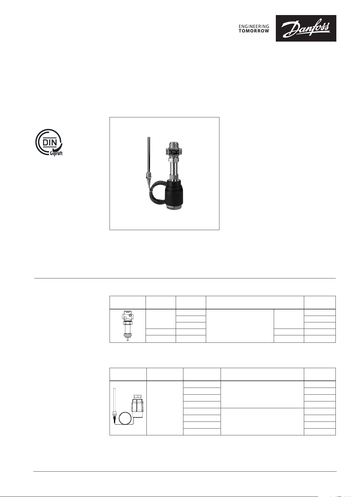
Temperature controller for steam (PN 25)
AV T / VGS - external thread
Description
The AVT / VGS controller is a self-acting
proportional temperature controller developed
primarily for steam or hot water applications for
temperatures up to 200 °C. Controller closes on
rising temperature.
The controller has a control valve VGS,
thermostatic actuator and handle for
temperature setting. Thermostatic actuator
consist of bellows, capillary tube and sensor.
The temperature controller is type-tested
according to EN 14597 and can be used in
combinations with safety temperature monitors
STM and safety temperature limiters STL.
Main data:
• DN 15-25
• kVS 1.0 - 6 . 3 m3/h
• PN 25
• Setting ranges:
−10 … 40 °C / 20 … 70 °C / 40 … 90 °C / 60 … 110 °C
and
10 … 45 °C / 35 … 70 °C / 60 … 100 ° C / 85 … 125 °C
• Temperature:
• Steam / circ. water / glycolic water up to 30 %:
2 … 200 °C
• Connections:
• Ext. thread (weld-on, thread and flange
tailpieces)
• Flow and return mounting.
Ordering
Example:
Temperature controller for steam,
DN 15; kVS 1.6; PN 25; setting range
40 … 90 °C; T
- 1× VGS DN 15 valve
Code No: 065B0787
- 1× AVT thermostatic actuator,
40 … 90 °C
Code No: 065-0602
Option:
- 1× Weld-on tailpieces
Code No: 0 03H6908
The valve will be delivered
(assembled) together with an
adapter M34 × M45.
200 °C; ext. thread
max
Picture
1)
DN k
(mm) (m3/h)
15
20 4.5 G 1 A 065B0789
25 6.3 G 1¼ A 065B0790
VS
1.0
1.6 065B0787
3.2 065B0788
Cylindrical external thread acc. to
Connection Code No.
ISO 228/1
VGS Valve
1)
Adapter M34 × M45 fo r connection to AVT thermos tat is factory assembled on t he valve.
(info: Adapter M34 × M30 fo r connection to AMV(E) electri cal actuators is part of t he valve delivery too.)
AVT Thermostatic actuator
Picture For valves
1)
conic male th read EN 10226 -1
2)
without imme rsion pocket
DN 15-25
Setting range
(°C)
−10 … + 4 0
20 … 70 065-0601
40 … 90 065-0602
60 … 110 065-0603
10 … 45
35 … 70 065-0605
60 … 100 065-0606
85 … 125 065-0607
Temperature sensor with brass immersion
pocket, length, connection
210 mm, R ¾
255 mm, R ¾
1)
1) 2)
065B0786
G ¾ A
Code No.
065-0600
065-0604
© Danfoss | 2017.07
VD.JK.C5.02 | 1
Data sheet Temperature controller for steam AVT/VGS (PN 25)
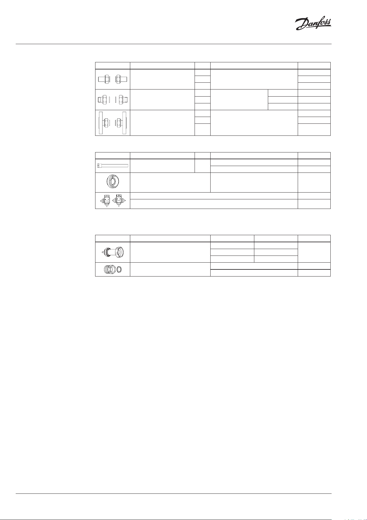
Ordering (continuous)
Accessories for valves
Picture Type designation DN Connection Code No.
15
Weld-on tailpieces
20 003H6909
-
25 00 3H6910
External thread tailpieces
15
Conical ex t. thread acc. to
20 R ¾ 003H6903
25 R 1 003H6904
EN 10226 -1
R ½ 0 03H6902
15
Flange tailpieces
20 003H 6916
Flanges PN 25, acc. to EN 1092-2
25 0 03H6 917
Accessories for thermostats
Picture Type designation PN Material Code No.
Immersion pocket 25
2)
Adapter
Stainless steel, mat. No. 1.4435 06 5-4 417
M34 × 1.5 mm / M45 × 1.5 mm 003H6927
Brass 065- 4416
Combination piece K2 003H6855
Combination piece K3 003H6856
1)
Not for AVT th ermostatic actuator code n umbers: 065-0604, 065-0605, 065-0606, 065-0607
2)
Adapter for VGS comb inations with thermostatic ac tuators AVT, temperature monito rs STM and temperature limite rs STL
Service kits
Picture Type designation for valves DN k
15 3.2
Valve body extension with stuf fing box
25 6.3
Housing of sensor stuffing box
for sensors Code No.
AVT R ¾ 065 -4421
VS
003H6908
003H 6915
1)
1)
Code No.
003H687720 4.5
2 | VD.JK.C5.02
© Danfoss | 2017.07
Data sheet Temperature controller for steam AVT/VGS (PN 25)
Technical data
Valves
Nominal diameter DN 15 20 25
kVS value m3/h 1.0 1.6 3.2 4.5 6.3
Stroke mm 3 5
Control ratio >1: 50
Control characteristic linear
Cavitation factor z ≥ 0.6 ≥ 0.55
Leakage acc. to standard IEC 534 % of k
Nominal pressure PN 25
Max. differential pressure bar 10
Media Steam / Circulat ion water / gl ycoli c water up t o 30 %
Media pH Min. 7, max. 10
Media temperature °C 2 … 20 0
Connections
Materials
Valve body Red bronze CuSn5ZnPb (Rg5)
Valve seat Stainless steel, mat. No. 1.4571
Valve cone Stainless steel, mat. No. 1.4122
Pressure relieve system Bellows
valve External thread
tailpieces Weld-on, external thread and flange
VS
≤ 0.05
Thermostatic actuator
Setting range X
Time constant T acc. to EN 14597 s max. 50 (210 mm), max. 30 (255 mm)
Gain K
Max. adm. temperature at sensor 50 °C above maximum setpoint
Max. amb. temperature at thermostat °C 0 … 70
Nominal pressure sensor
Nominal pressure immersion pocket
Capillary tube length 5 m (210 mm), 4 m (255 mm)
Materials
Temperature sensor Cooper
Immersion pocket
Handle for temp. setting Polyamide, glass fiber-reinforced
Scale carrier Polyamide
1)
for sensor 210 mm
s
s
1)
Ms design Brass, nickel-plated
Stainless steel design Mat. No. 1.4435 (210 mm)
°C
mm/°K
PN 25
−10 … 4 0 / 20 … 70 / 40 … 90 / 60 … 110
10 … 45 / 35 … 70 / 60 … 100 / 85 … 125
0.3 (210 mm), 0.7 (255 mm)
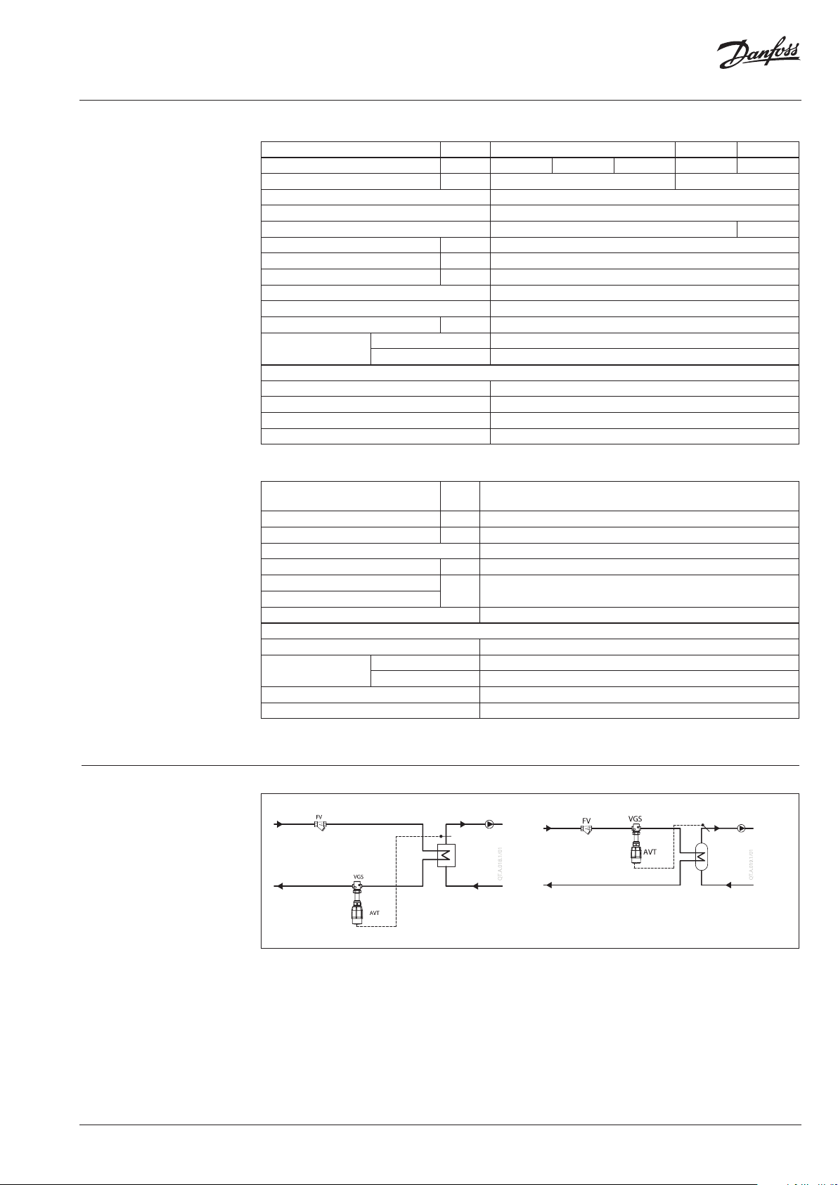
Application principles
© Danfoss | 2017.07
VD.JK.C5.02 | 3
Data sheet Temperature controller for steam AVT/VGS (PN 25)
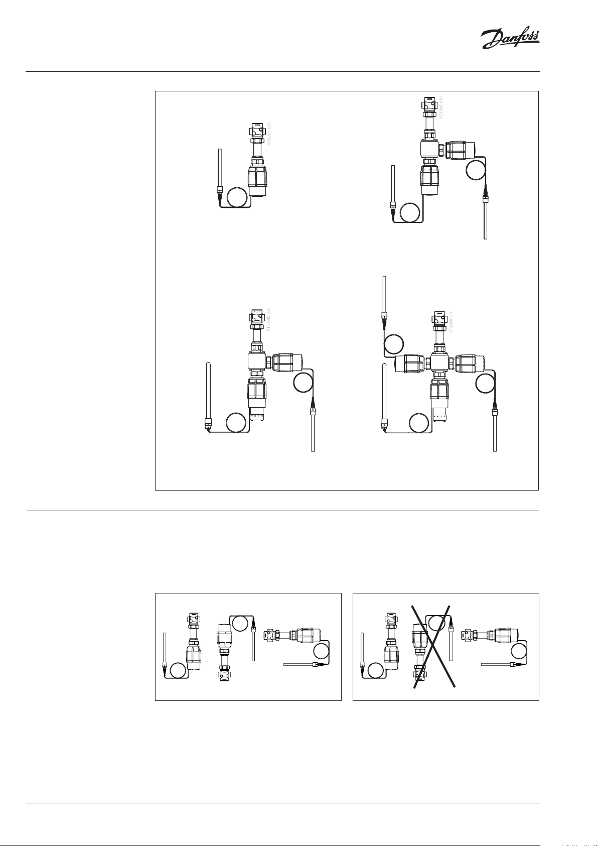
Combinations
Example:
Temperature controller with safety
temperature monitor for steam,
DN 15, kVS 1.6, PN 25, setting range
40 … 90 °C, T
- 1× VGS DN 15 valve
Code No: 065B0787
- 1× AVT thermostatic actuator,
40 … 90 °C
Code No: 065-0602
- 1× STM thermostat, 30 … 110 °C
Code No: 065-0608
- 1× K2 combination piece
Code No: 003H6855
Products will be delivered seperatly.
Note:
For safety te mperature monitor
STM / VGS data and safety temperatu re
limiter STLS d ata see relevant data sheet
200 °C, ex t. thread
max
AVT / VGS
- temperature controller
AVT / AVT / VGS
- two temperature controllers
STM / AVT / VGS
- temperature controller with safety
temperature monitor for steam
Temperature controllerInstallation positions
Up to media temperature of 160 °C the
controllers AVT / VGS can be installed in any
position.
STM / AVT / AVT / VGS
- two temperature controllers with safety
temperature monitor for steam
For higher temperatures the controllers
AVT / VGS have to be installed horizontal and
in horizontal pipes with the actuator oriented
downwards.
4 | VD.JK.C5.02
© Danfoss | 2017.07

Data sheet Temperature controller for steam AVT/VGS (PN 25)
Installation positions
(continuous)
Temperature sensor
The place of installation must be chosen in a way
that the temperature of the media is directly
taken without any delay. Avoid overheating of
temperature sensor. The temperature sensor
must be immersed into the media in its full
length.
Temperature sensor 210 mm R¾”:
• The temperature sensor may be installed in
any position.
Temperature sensor 255 mm R¾”:
• The temperature sensor must be installed as
shown on the picture.
Pressure temperature
diagram
CuSn5ZnPb (Rg5) PN 25
Maximum allowed operating pressure as a function of media temperature (according to EN 1092-3).
© Danfoss | 2017.07
VD.JK.C5.02 | 5
Data sheet Temperature controller for steam AVT/VGS (PN 25)
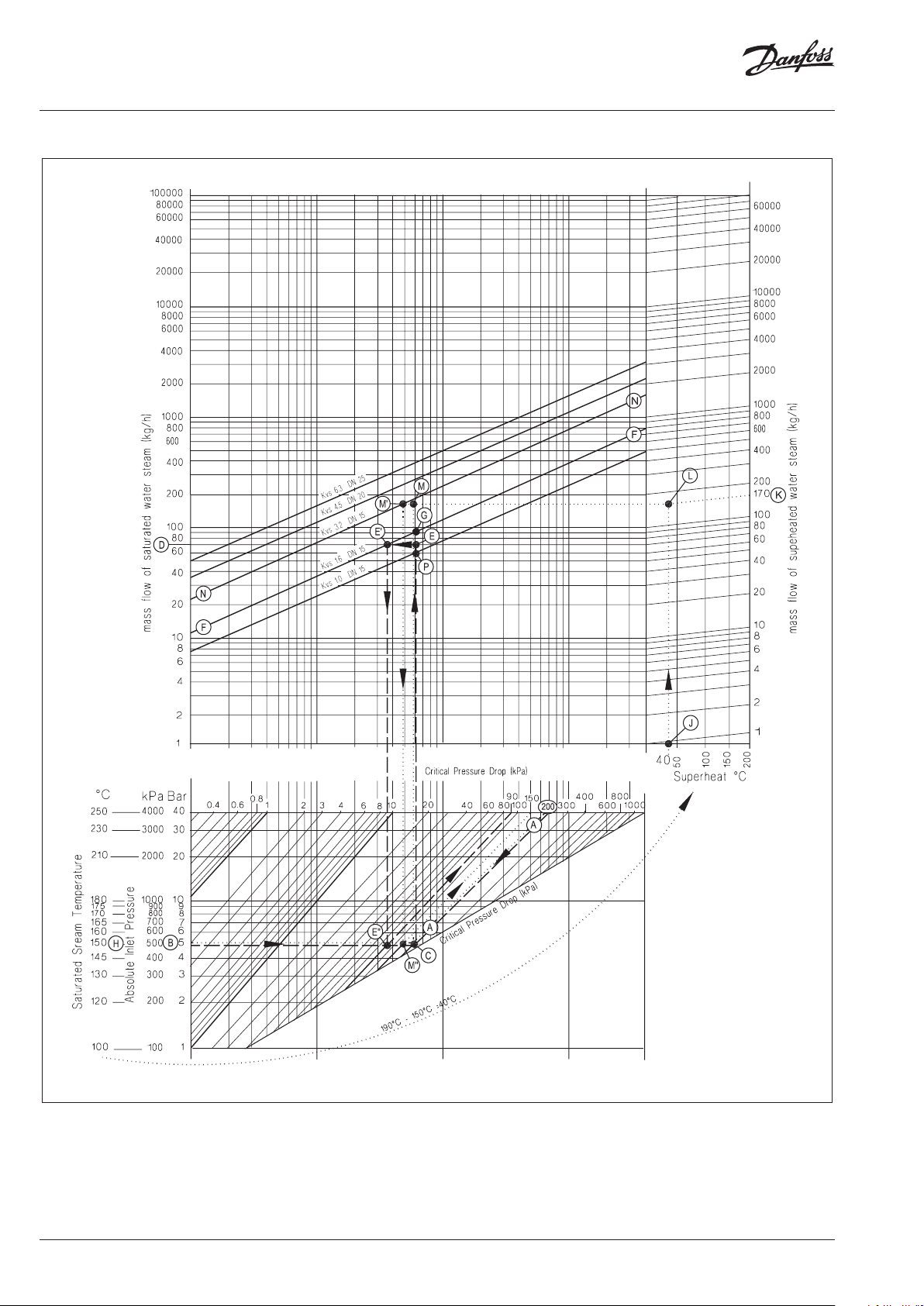
Valve sizing
6 | VD.JK.C5.02
Steam valve sizing is based on 40 % drop of the
steam pressure across the valve when fully open.
At this condition the steam is travelling at or
close to its critical velocity (approx. 300 m/s) and
throttling would occur over the full valve stroke.
If the steam is travelling slower than this, then
the first part of the valve stroke would merely
increase the velocity of the steam without
reducing the volumetric flow.
© Danfoss | 2017.07

Data sheet Temperature controller for steam AVT/VGS (PN 25)
Valve sizing (continuous) 1. For saturated steam
Given data:
Flow rate: 70 kg/h
Absolute inlet pressure: 5 bar (500 kPa)
Remark:
For this example follow dashed line
The absolute inlet pressure is 500 kPa. Critical
pressure drop (40 % of 500 kPa) is 200 kPa. Locate
the diagonal line corresponding to the pressure
drop of 200 kPa (line A-A).
Read the absolute inlet pressure on the lower left
hand scale (point B), and draw a horizontal line
across until it meets the pressure drop diagonal
A-A at point C.
From this point C extend a vertical line upwards
until it meets the horizontal line representing
the steam flow of 70 kg/h from point D. The
intersection of this is point E.
The nearest diagonal kVS line above this is line
F-F with a kVS of 1.6. If the ideal valve size is not
available the next largest size should be selected
to ensure design flow.
The pressure drop through valve at the flow rate
is found by the intersection of the 70 kg/h line
with F-F (point E’) and dropping a vertical line
downwards; this actually hits the horizontal line
for 500 kPa absolute inlet pressure (point E’’)
at a pressure drop diagonal of 90 kPa. This is
only 18 % of the pressure drop accross the valve
and the control quality will not be good until
the valve has partially closed. As with all steam
valves this compromise is necessary since the
next smaller valve would not pass the required
flow (maximum flow would be about 60 kg/h;
point P).
The maximum flow for the same inlet pressure
is found by extending the vertical line (C-E)
through point E until it crosses the kVS 1.6 line F-F
(point G) and reading off the flow (90 kg/h).
2. For superheated steam
Given data:
Flow rate: 170 kg/h
Absolute inlet pressure: 5 bar (500 kPa)
Steam temperature: 190 °C
Remark:
For this exampl e follow dotted line
The procedur e for superheated steam is muc h the same as for
saturated steam , but uses a different flow s cale which slightly
elevates the read ings according to the degree of sup erheat.
As before, the diagonal critical pressure drop
line A-A is located at 40 % of 500 kPa (200 kPa).
The horizontal inlet pressure line through
point B is now extended to the left to read off
the corresponding saturated steam temperature
at point H (150 °C). The difference between
the saturated steam temperature and the
superheated steam temperature is
190 °C − 150 °C = 40 °C (see point J).
The superheated steam flow 170 kg/h is found
on the upper right hand scale (point K). From
here the diagonal line is followed down until it
meets a vertical line from the steam temperature
elevation (40 °C, point J) at point L.
As before, the horizontal line through point B
is drawn to cut line A-A at point C. The point
where the vertical line from point C meets the
horizontal line from point L is the operating
point (point M). This horizontal line, L-M, is the
corrected flow line. The nearest diagonal line
above this is line N-N with a kVS 3.2. A vertical
line dropped from the intersection of L-M line
with line N-N (point M’) intersects the 500 kPa
absolute inlet pressure line (point M’’) at a
pressure drop diagonal of about 150 kPa.
This is about 30 % of the pressure drop accross
the valve which will give reasonable control
quality (compared to recommended ratio of
40 %).
© Danfoss | 2017.07
VD.JK.C5.02 | 7

Data sheet Temperature controller for steam AVT/VGS (PN 25)
Design
1. Valve VGS
2. Valve insert
3. Pressure relieved valve cone
4. Valve stem
5. Valve body extension
6. Union nut
7. Thermostatic actuator AVT
8. Thermostat stem
9. Bellows
10. Setting spring for
temperature control
11. Handle for temperature
setting, prepared for sealing
12. Scale carrier
13. Capillary tube
14. Flexible protected pipe
(only at AVT 255 mm)
15. Temperature sensor
16. Immersion pocket
17. Sensor stuffing box
18. Housing of sensor stuffing
box
Function By increasing of media temperature valve
AVT 255
Media temperature changes cause pressure
changes in temperature sensor. Resulting
pressure is being transferred through the
capillary tube to the bellows. Bellows moves
AV T 210
cone moves towards the seat (valve closes), by
decreasing of media temperature valve cone
moves away from the seat (valve opens).
thermostat stem and opens or closes the valve.
Handle for temperature setting can be sealed.
Settings
Temperature setting
Temperature setting is being done by the
adjustment of the setting spring for temperature
control. The adjustment can be done by means
of handle for temperature setting and / or
temperature indicators.
Adjustment diagram Temperature setting
Relation between scale numbers 1-5 and closing
temperature.
Note: The va lues given are approximate
AVT Thermostat ... 210 mm
AVT Thermostat ... 255 mm
Note:
STM Safety te mperature monitor (actuato r):
temperature sca le is already written on th e product
8 | VD.JK.C5.02
© Danfoss | 2017.07

Data sheet Temperature controller for steam AVT/VGS (PN 25)
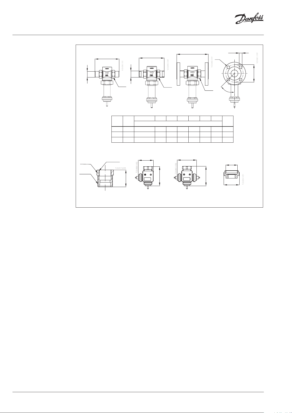
Dimensions
AVT / VGS
DN
15 65 257 34
20 70 257 34
25 75 257 37
L H H
mm
L
2
H
H
150
H
Ø 76
VGS
2
DN
15 178 1.3
20 178 1.4
25 178 1.6
H Weight
(mm) (kg)
AVT
Typ e Weight
sensor 210 mm
sensor 255 mm 1.6
Ø 16
kg
1.5
223
SW 22
AV T 210
Ø 16
M22×1
Immersion pocket
215
10
SW 27
AV T 210
Ø 19
R ¾
SW 22
AVT 255
266
R ¾
© Danfoss | 2017.07
VD.JK.C5.02 | 9
Data sheet Temperature controller for steam AVT/VGS (PN 25)
Dimensions (continuous)
d
SW 27
R ¾
Housing of sensor
stuffing box
L
L
L
3
2
1
R
SW
DN R
SW d L1 2)L2L3k d
1)
SW
mm
15 ⁄ 32 (G ⁄A) 21 130 120 139 65 14 4
20 ⁄ 41 (G 1A) 26 150 131 154 75 14 4
25 1 50 (G 1⁄A) 33 160 145 159 85 14 4
1)
Conical ex t. thread acc. to EN 10226-1
2)
Flanges PN 25, acc. to EN 1092-2
M22×1
85
30
Combination piece K2
109
108
109
Combination piece K3
d
2
n
SW
45°
2
n
M34
M45
Adapter
M34 × 1.5 mm / M45 × 1.5 mm
k
10 | VD.JK.C5.02
© Danfoss | 2017.07

Data sheet Temperature controller for steam AVT/VGS (PN 25)
© Danfoss | 2017.07
VD.JK.C5.02 | 11

Danf
already on order pro
All trademarks in this material are property of the respec
Data sheet Temperature controller for steam AVT/VGS (PN 25)
oss can accept no responsibility for possible errors in catalogues, brochures and other printed material. Danfoss reserves the right to alter its products without notice. This also applies to products
vided that such alterations can be made without subsequential changes being necessary eady agreed.
12 | VD.JK.C5.02
tive companies. Danfoss and the Danfoss logotype are trademarks of Danfoss A/S. All rights reserved.
© Danfoss | DHS-SRMT/SI | 2017.07
 Loading...