

Page 1
Data sheet
TR(TW)700
Temperature controller for heating (PN 25)
AVT / VG - external thread
AVT / VGF - flange
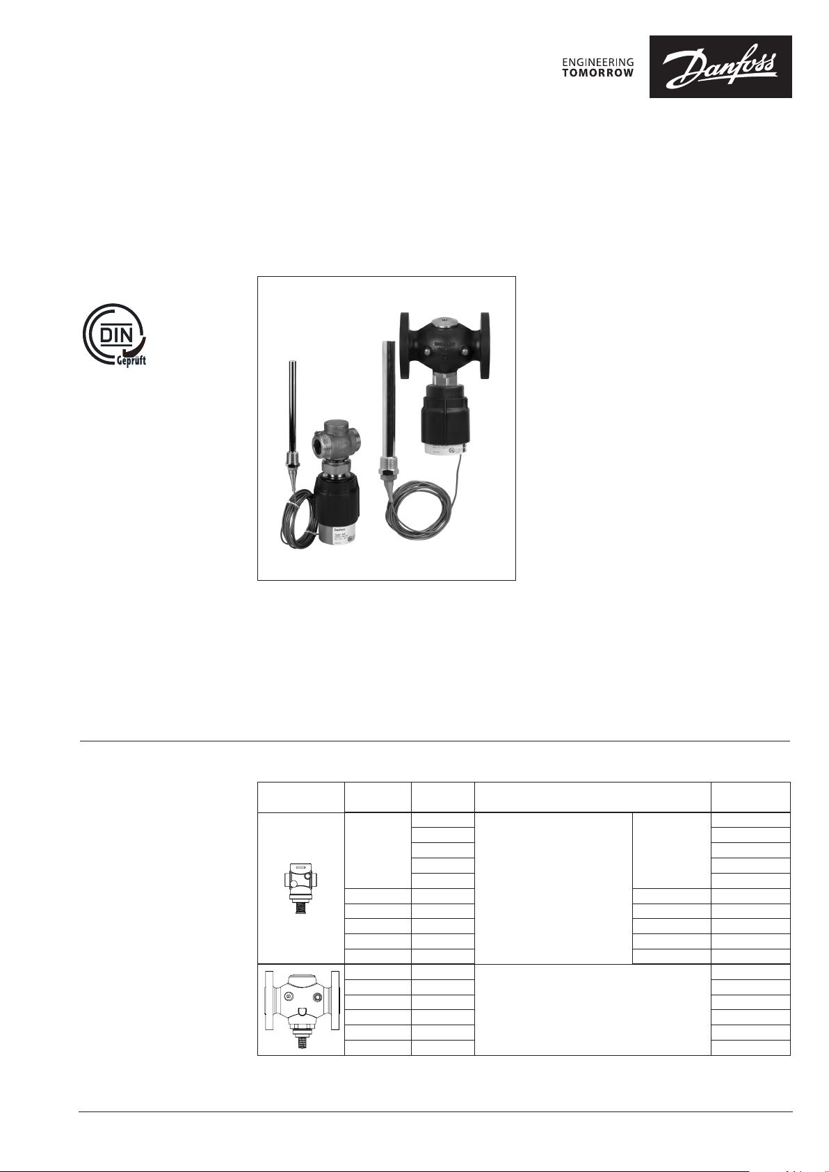
Description
AVT / VGF
AVT / VG
The AVT / VG(F) controller is a self-acting
proportional temperature controller developed
primarily for domestic hot water (DHW)
production:
- Hot water tanks
- Storage charge systems
- Instantaneous domestic hot water production
(AVT 255 mm version)
It can be used in mixing loops and room heating
systems as well.
Controller closes on rising temperature.
The controller has a control valve VG(F),
thermostatic actuator and handle for
temperature setting. Thermostatic actuator
consist of bellows, capillary tube and sensor.
The temperature controller is type-tested
according to EN 14597 and can be used in
combinations with safety temperature monitors
STM and safety temperature limiters STL.
Main data:
• DN 15-50
• kVS 0.4 -25 m3/h
• PN 25
• Setting ranges:
−10 … 40 °C / 20 … 70 °C / 40 … 90 °C / 60 … 110 °C
and
10 … 45 °C / 35 … 70 °C / 60 … 100 °C / 85 … 125 °C
• Temperature:
- Circ. water / glycolic water up to 30 %:
2 … 150 °C
• Connections:
- Ext. thread (weld-on, thread and flange
tailpieces)
- Flange
• Flow and return mounting.
Ordering
Example:
Temperature controller, DN 15;
kVS 1.6 ; PN 25; setting range 40…90°C
T
150 °C; ext. thread
max
- 1× VG DN 15 valve
Code No: 065B0772
- 1× AVT thermostatic actuator,
40 … 90 °C
Code No: 065-0598
Option:
- 1× Weld-on tailpieces
Code No: 003H6908
© Danfoss | 2020.08
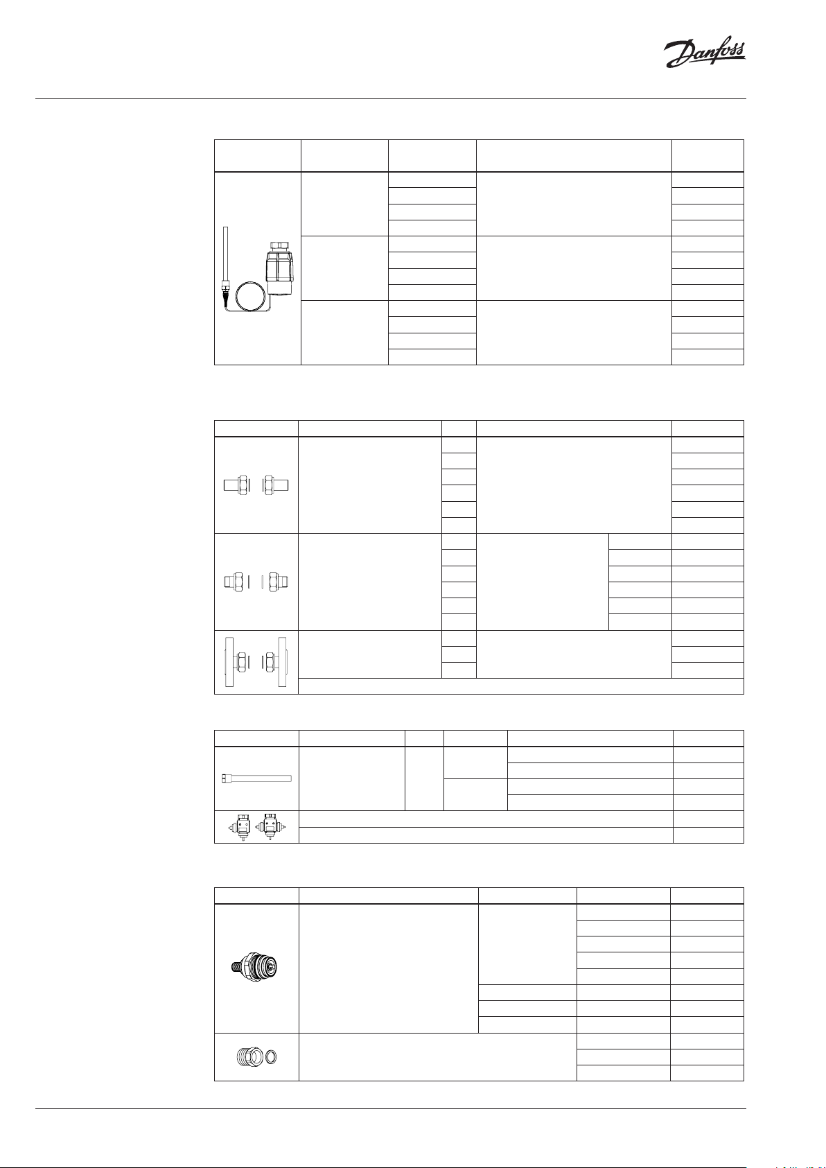
VG, VGF valve
;
Picture
DN k
(mm) (m3/h)
15
20 6.3 G 1 A 065B0775
25 8.0 G 1¼ A 065B0776
32 12.5 G 1¾ A 065B0777
40 16 G 2 A 065B0778
50 20 G 2½ A 065B0779
15 4.0
20 6.3 065B0781
25 8.0 065B0782
32 12.5 065B0783
40 20 065B0784
50 25 065B0785
VS
0.4
1.0 065B0771
1.6 065B0772
2.5 065B0773
4.0 065B07 74
Cylindrical external thread acc. to
Connection Code No.
065B0770
G ¾ A
ISO 228 / 1
065B0780
Flanges PN 25, acc. to EN 1092-2
AI173286467274en-000503 | 1
Page 2
Data sheet Temperature controller AVT / VG(F) (PN 25)
Ordering (continuous)
AVT thermostatic actuator
Picture For valves
1)
conic male thre ad EN 10226
2)
without immersion pocket
DN 15-2 5
DN 32-50
DN 15-50
Setting range
(°C)
−10 … +4 0
20 … 70 065-0597
40 … 90 065-0598
60 … 110 065-0599
−10 … +4 0
20 … 70 065-0601
40 … 90 065-0602
60 … 110 065-0603
10 … 45
35 … 70 065-0605
60 … 100 065-0606
85 … 12 5 065-0607
Temperature sensor with brass immersion
pocket, length, connection
170 mm, R ½
210 mm, R ¾
255 mm, R ¾
1)
1)
1) 2)
Accessories for valves
Picture Type designation DN Connection Code No.
15
20 003H6909
Weld-on tailpieces
External thread tailpieces
Flange tailpieces
25 00 3H6910
32 0 03 H69 11
-
40 065B2006
50 065B2007
15
R ½ 003H6902
20 R ¾ 003H6903
25 R 1 003H6904
Conical ex t. thread acc. to EN
32 R 1¼ 003H6905
10226-1
40 R 1½ 065B2004
50 R 2 065B2005
15
20 003H6 916
Flanges PN 25, acc. to EN 1092-2
25 0 03H6 917
Code No.
065-0596
065-0600
065-0604
003H6908
003H6 915
2 | AI173286467274en-000503
Accessories for thermostats
Picture Type designation PN For valves Material Code No.
Brass 06 5-4 414
Brass
Immersion pocket 25
DN 15-2 5
DN 32-50
Stainless steel, mat. No. 1.4571 065- 4415
Stainless steel, mat. No. 1.4435 06 5-4 417
Combination piece K2 003H6855
Combination piece K3 003H6856
1)
Not for AV T thermostatic actuator code numbers: 065-0604, 065- 0605, 065-0606, 065-0607
Service kits
Picture Type designation DN (mm) kVS (m3/h) Co de No.
0.4 003H6869
1.0 003H6870
15
Valve insert
1.6 003H6871
2.5 003H6872
4.0 0 03H6873
20 6.3 003 H6874
25 8.0 003H6 875
32 / 40 / 50 125 / 16 / 20 / 25 003H6876
for sensors Code No.
Housing of sensor stuffing box
AVT 170 R 1/ 065- 4420
AVT 210, 255 R / 065-44 21
© Danfoss | 2020.08
065- 4416
1)
1)
1)
1)
Page 3
Data sheet Temperature controller AVT / VG(F) (PN 25)
Technical data
Valves
Nominal diameter DN 15 20 25 32 40 50
k
value m3/h 0.4 1.0 1. 6 2.5 4.0 6.3 8 12.5 16 / 20 1)20 / 25
VS
Stroke mm 3 5 10
Control ratio > 1:50
Control characteristic linear
Cavitation factor z ≥ 0.6 ≥ 0.55 ≥ 0.5
Leakage acc. to standard IEC 534 % of k
VS
Nominal pressure PN 25
Max. differential pressure bar 20 16
Medium Circulation water / glycolic water up to 30 %
Medium pH Min. 7, ma x. 10
Medium temperature
°
C 2 … 150
valve
Connections
tailpieces
Materials
Valve body
thread Red bronze CuSn5ZnPb (Rg5)
flange - Ductile iron EN -GJS-400-18-LT (GGG 40.3)
Valve seat Stainless steel, mat. No. 1.4571
Valve cone Dezincing free brass CuZn36Pb2As
Sealing EPDM
Pressure relieve system Piston
1)
Flange valve bod y
≤ 0.02 ≤ 0.05
External thread
- Flange
Weld-on and external thread
Flange -
Ductile iron
EN-GJS-400-18-LT (GGG
40. 3)
1)
Application principles
Thermostatic actuator
Setting range X
s
°C
Time constant T acc. to EN 14597 s max. 50 (170 mm, 210 mm), max. 30 (255 mm)
Gain K
s
mm / °K
Max. adm. temperature at sensor 50 °C above maximum setpoint
Max. amb. temperature at sensor
Nominal pressure sensor
Nominal pressure immersion pocket
°C
PN 25
Capillary tube length 5 m (170 mm, 210 mm), 4 m (255 mm)
Materials
Temperature sensor Cooper
Ms design Brass, nickel-plated
Immersion pocket
1)
Stainless steel design Mat. No. 1.4571 (170 mm), mat. No. 1.4435 (210 mm)
Handle for temp. setting Polyamide, glass fiber-reinforced
Scale carrier Polyamide
1)
for sensor 170 and 210 mm
−10 … 40 / 20 … 70 / 40 … 90 / 60 … 110
10 … 45 / 35 … 70 / 60 … 100 / 85 … 125
0.2 (170 mm), 0.3 (210 mm), 0.7 (255 mm)
0 … 70
© Danfoss | 2020.08
AI173286467274en-000503 | 3
Page 4
Data sheet Temperature controller AVT / VG(F) (PN 25)
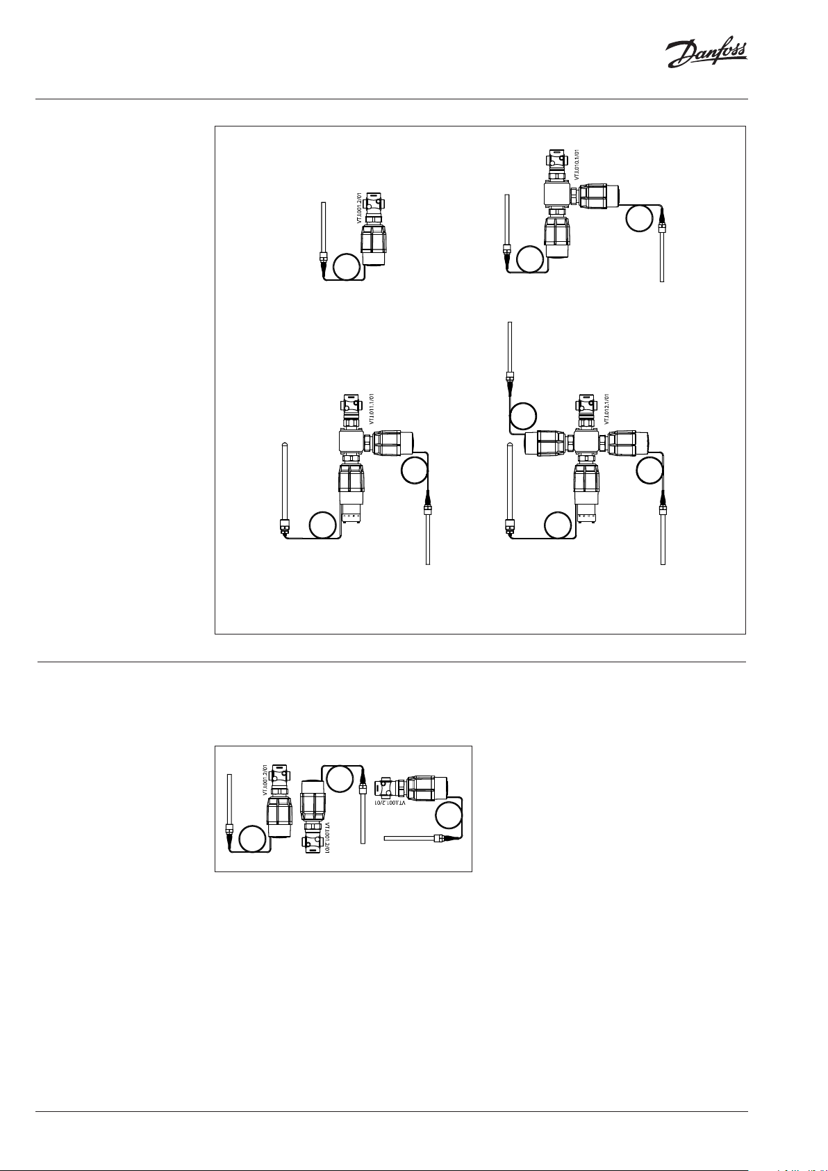
Combinations
Example:
Temperature controller with safety
temperature monitor, DN 15; kVS 1.6 ;
PN 25; setting range 40 … 90 °C;
T
150 °C; ext. thread
max
- 1× VG DN 15 valve
Code No: 065B0772
- 1× AVT thermostatic actuator,
40 … 90 °C
Code No: 065-0598
- 1× STM thermostat, 30 … 110 °C
Code No: 065-0608
- 1× K2 combination piece
Code No: 003H6855
Products will b e delivereed separatly
Note:
For safety temperature monitor
STM / VG(F) data and safet y
temperature limiter STLV data see
relevant data sheet.
AVT / VG
- temperature controller
AVT / AVT / VG
- two temperature controllers
Installation positions
STM / AVT / VG
- temperature controller with
safety temperature monitor
Temperature controller
Temperature controller AVT / VG(F) can be
installed in any position.
STM / AVT / AVT / VG
- two temperature controllers with
safety temperature monitor
4 | AI173286467274en-000503
© Danfoss | 2020.08
Page 5

Data sheet Temperature controller AVT / VG(F) (PN 25)
Installation positions
(continuous)
Temperature sensor
The place of installation must be chosen in a way
that the temperature of the medium is directly
taken without any delay. Avoid overheating of
temperature sensor. The temperature sensor
must be immersed into the medium in its full
length.
Temperature sensors 170 mm R ½ and 210 mm R ¾
- The temperature sensor may be installed in
any position.
Temperature sensor 255 mm R ¾
- The temperature sensor must be installed as
shown on the picture.
Pressure temperature
diagram
EN-GJS-400-18-LT (GGG 40.3) PN 25
CuSn5ZnPb (Rg5) PN 25
Maximum allowed operating pressure as a function of medium temperature (according to EN 1092-2 and EN 1092-3).
© Danfoss | 2020.08
AI173286467274en-000503 | 5
Page 6

Data sheet Temperature controller AVT / VG(F) (PN 25)
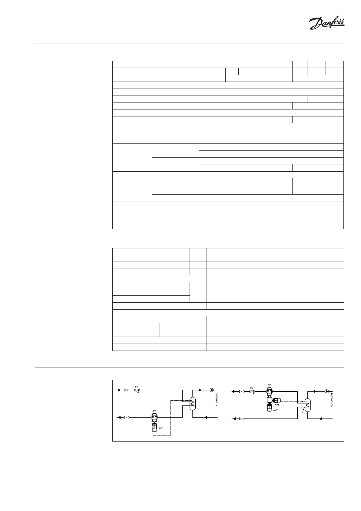
Valve sizing
Given data:
P
= 14 kW
max
∆t = 20 K
∆pv = 0.15 bar
P
- heating power (kW)
max
∆t -temperature difference (K)
∆pv - differential pressure across the valve
Maximum flow Q
calculated according to formula:
max
= 0.6 m3/h
max
max
Q
Q
(m3/h) through the valve is
max
8 6 , 0P
t
86,014
20
kv value is calculated according to formula:
Q
max
k
v
p
6,0
1 5, 0
V
kv = 1.5 m3/h
Chosen kVS = 1.6 m3/h
or read from the sizing diagram by taking a
line through Q scale (0.6 m3/h) and ∆pv scale
(0.15 bar) to intersect kv-scale at 1.5 m3/h
Chosen kVS = 1.6 m3/h
Solution:
The example selects
1) ext. thread valve VG DN 15, kVS value 1.6 or
2) flange valve VGF DN 15, kVS value 1.6
6 | AI173286467274en-000503
© Danfoss | 2020.08
Page 7

Data sheet Temperature controller AVT / VG(F) (PN 25)
Design
1. Valve VG(F)
2. Valve insert
3. Pressure relieved valve cone
4. Valve stem
5. Union nut
6. Thermostatic actuator AVT
7. Thermostat stem
8. Bellows
9. Setting spring for
temperature control
10. Handle for temperature
setting, prepared for sealing
11. Scale carrier
12. Capillary tube
13. Flexible protected pipe
(only at AVT 255 mm)
14. Temperature sensor
15. Immersion pocket
16. Sensor stuffing box
17. Housing of sensor stuffing
box
Function
AV T 170
AVT 255
AV T 210
Medium temperature changes cause pressure
changes in temperature sensor. Resulting
pressure is being transferred through the
capillary tube to the bellows. Bellows moves
thermostat stem and opens or closes the valve.
By increasing of medium temperature valve
cone moves towards the seat (valve closes), by
decreasing of medium temperature valve cone
moves away from the seat (valve opens).
Handle for temperature setting can be sealed.
Settings
Temperature setting
Temperature setting is being done by the
adjustment of the setting spring for temperature
control. The adjustment can be done by means
of handle for temperature setting and/or
temperature indicators.
Adjustment diagram Temperature setting
Relation between scale numbers 1-5 and closing
temperature.
Note: The values given are approximate
AVT Thermostat ... 170 mm, 210 mm
AVT Thermostat ... 255 mm
© Danfoss | 2020.08
AI173286467274en-000503 | 7
Page 8

Data sheet Temperature controller AVT / VG(F) (PN 25)
Dimensions
L
1
L
2
H
H
L L1H H1H2H
DN
mm
15 65 130 18 0 229 34 47
20 70 15 0 180 229 34 52
25 75 16 0 18 0 229 37 57
32 100 180 2 21 2 21 62 70
40 110 200 221 221 62 75
50 130 230 2 21 2 21 62 82
Note: other flange dimensions - see table for tailpieces
L
L
1
H
2
H
1
H
2
H
H
3
H
1
H
150
Ø 76
AVT
3
1
H
H
2
H
Typ e Weight
sensor 170 mm
sensor 210 mm 1.5
sensor 255 mm 1.6
L
1
H
H
2
H
1.3
kg
L
H
8 | AI173286467274en-000503
VG DN 15-25 VGF DN 15-25 VGF DN 32-50VG DN 32-50
VG
L H H1 H2
DN
15 65 80 34 46 0.7
20 70 80 34 46 0.8
25 75 83 37 46 0.9
32 10 0 151 63 88 3.0
40 110 151 63 88 3.1
50 13 0 151 63 88 3.8
mm
Weight
(kg)
VGF
L H H1 H2
DN
mm
15 130 14 4 48 96 3.3
20 150 149 53 96 4.1
25 160 15 4 58 96 4.7
32 18 0 158 70 88 7. 5
40 200 163 75 88 9.0
50 230 17 1 83 88 11.1
Note: other flange dimensions - see table for tailpieces
Weight
(kg)
© Danfoss | 2020.08
Page 9

Data sheet Temperature controller AVT / VG(F) (PN 25)
Dimensions (continuous)
L
L2L
1
k d
3
2
L
3
d
DN R
R
1)
L
2
SW d L
2)
1
mm
d
2
k
n
15 ⁄ 32 (G ⁄A) 21 130 131 139 65 14 4
20 ⁄ 41 (G 1A) 26 150 144 154 75 14 4
25 1 50 (G 1⁄A) 33 160 16 0 159 85 14 4
32 1⁄ 63 (G 1¾A) 42 - 17 7 18 4 100 18 4
40 1 ⁄ 70 (G 2A) 47 - 195 204 110 18 4
50 2 82 (G 2½A) 60 - 252 234 125 18 4
1)
Conical ex t. thread acc. to EN 10226-1
2)
Flanges PN 25, acc. to EN 1092-2
Ø 16
Ø 16
Ø 19
174
SW 17
AV T 170
SW 22 (R ½)
SW 27 (R ¾)
R ½; R ¾
Ø 9.5
170
6
M14×1
AV T 170
Immersion p ocket
M 14×1 (R ½)
M 22×1 (R ¾)
Housing of sensor
stuffing box
Ø 12
SW 22
30 (R ¾)
25 (R ½)
R ½
Combination piece K2
223
SW 22
AV T 210
85
M22×1
109
215
10
SW 27
R ¾
AV T 210
Immersion p ocket
Combination piece K3
108
SW 22
AVT 255
266
R ¾
109
© Danfoss | 2020.08
AI173286467274en-000503 | 9
Page 10

Data sheet Temperature controller AVT / VG(F) (PN 25)
10 | AI173286467274en-000503
© Danfoss | 2020.08
Page 11

Data sheet Temperature controller AVT / VG(F) (PN 25)
© Danfoss | 2020.08
AI173286467274en-000503 | 11
Page 12

Data sheet Temperature controller AVT / VG(F) (PN 25)
12 | AI173286467274en-000503
© Danfoss | DHS-SRMT/SI | 2020.08
 Loading...