

Data sheet
Temperature controller AVTB (PN 16)
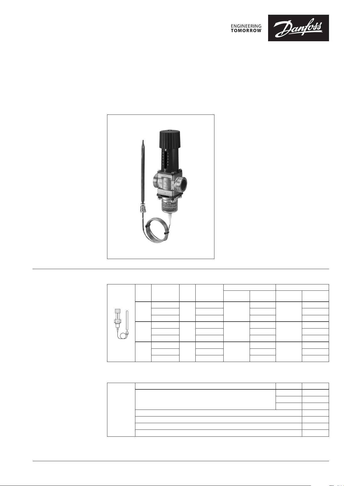
Description AVTB is self-acting temperature controller used
to control the water temperature in hot water
tanks, heat exchangers, oil preheaters, etc.
Controller closes on rising temperature.
The controller has a control valve, thermostatic
actuator and handle for temperature setting.
Thermostatic actuator consist of a bellows,
capillary tube and sensor.
Main data:
• DN 15, 20, 25
• kVS 1.9; 3.4; 5.5m3/h
• PN 16
• Setting range:
0 … 30°C/20 … 60°C/30 … 100°C
• Temperature:
- Circulation water/glycolic water up to 30%:
2 … 130°C
• Connections:
- Int. thread
- Ext. thread (weld-on and ext. thread
tailpieces)
• Flow or return mounting, depending on
sensor type.
Ordering
1)
Complete control ler including sensor
stuffi ng box. The immersion p ocket is
an accessor y.
2)
Including sma ll sensor Ø 9.5 × 180.
The sensor is to be m ounted where the
system tempe rature is warmer than
the temperatu re in the valve housing.
Insulaton disk is fac tory mounted on
the controller.
3)
Including sma ll sensor Ø 9.5 × 150.
Capillar y tube length 2.3 m.
4)
Including se nsor Ø 18 × 210; available
on request
Example:
Temperature controller; DN 15;
kVS 1.9; PN 16; setting range
30 … 100°C; T
- 1× AVTB DN 15 Controller
Code No: 0 0 3N5141
Option:
- 1× Imm. pocket, brass
Code No: 013U 029 0
- 1× Weld-on taipieces
Code No: 003H6908
130 °C; ext. thread
max
AVTB Controller
DN
15
20
25
Capillary tube length: 2 m.
Setting
range
(°C)
0 … 30
20 … 60 90 003N8229
30 … 100 130 003N 8141
0 … 30
20 … 60 90 003N8230
30 … 100 130 003 N8142
0 … 30
20 … 60 90 003N8253
30 … 100 130 003N8143
k
VS
(m3/h)
1.9
3.4
5.5
Max. se nsor
temp.
(°C)
55
55
55
Internal thread External thread
Connection
IS O 7/1
Rp ½
Rp ¾
Rp 1
Code No.
003N2232
003N3232
003N4232
1)
4)
2)
3)
4)
2)
3)
4)
2)
3)
Connection
ISO 228/1
Service kits
Type designation for Code No.
Repair set
Two diaphragms, two O-rings, one rubber cone,
one tube of grease and eight valve cover screws
Thermostatic actuator 0 … 30 °C, sensor Ø 18 × 210, 2m 003N0075
Thermostatic actuator 20 … 60 °C, sensor Ø 9.5 × 180, 2m 00 3N0130
Thermostatic actuator 30 … 100 °C, sensor Ø 9.5 × 150, 2.3m 00 3N0131
Housing of sensor stuffing box, R ½ × M14 × 1 mm, rubber EPDM Ø 12.6 × 4 × 6 mm 013U 8102
1)
For thermostatic a ctuators 20 … 60°C and 30 … 100° C; code includes housing an d gasket of sensor stuffi ng box
Code No.
003 N5101
G ¾ A
G 1 A
G 1¼ A
DN 15 003N4006
DN 20 003N4007
DN 25 003N4008
00 3N 5114
00 3N5141
003 N5102
00 3N 5115
00 3N5142
003 N5103
00 3N 5116
003N5143
1)
4)
2)
3)
4)
2)
3)
4)
2)
3)
1)
© Danfoss | 2018.04 VD.JK.Z4.02 | 1
Data sheet Temperature controller AVTB (PN 16)
Ordering (continuous)
Technical data
Accessories
Picture Type designations DN Connection Code No.
15
Weld-on taipieces
External thread taipieces
Immersion pocket
Insulation disk
1)
For details see “ Installation positions” sec tion
Nominal diameter DN 15 20 25
k
value m3/h 1.9 3.4 5.5
VS
Cavitation factor z 0.4
Nominal pressure PN 16
Max. differential pressure bar 10
Medium Circulation water/glycolic water up to 30%
Medium pH Min. 7, max. 10
Medium temperature
Connections
Materials
Valve body
Valve seat Cr Ni steel, DIN 17440, W.No. 1.4301
Valve cone NBR-rubber
Spindle Dezincing-free brass, BS 2872/CZ132
Other metal parts Dezincing-free brass, BS 2874/CZ132
Diaphragms, O-rings EPDM-rubber
Temperature sensor Copper
Sensor charge
1)
o
valve Internal and external thread
tailpieces Weld-on and external thread
internal thread MS 58, hot-pressed, DIN 17660, W.No. 2.0402, CuZn40Pb2
external thread Dezincing-free brass, BS 2872/CZ132
20 003H6909
25 00 3H6910
15
20 R ¾” 003H6903
25 R 1” 003H6904
Rp ½ × M14 × 1 mm, brass 182 mm, without sens.stuff. box
Rp ½ × M18 × 1.5 mm, st. steel 182 mm, with sens.stuff. box
Rp ¾ × M22 × 1 mm, brass 220 mm, with sens.stuff. box
Rp ¾ × M22 × 1 mm, st. steel 220 mm, with sens.stuff. box
C 2 … 130
0 … 30 oC R 152 A, C2H4F2
20 … 60 oC Butane R600, C4H10
30 … 100 oC Carbon dioxide, CO2
Con. ext. thread acc. to
EN 10226 -1
-
R ½” 003H6902
003H6908
013U 0290
003 N0196
003N0050
003 N0192
003N4022
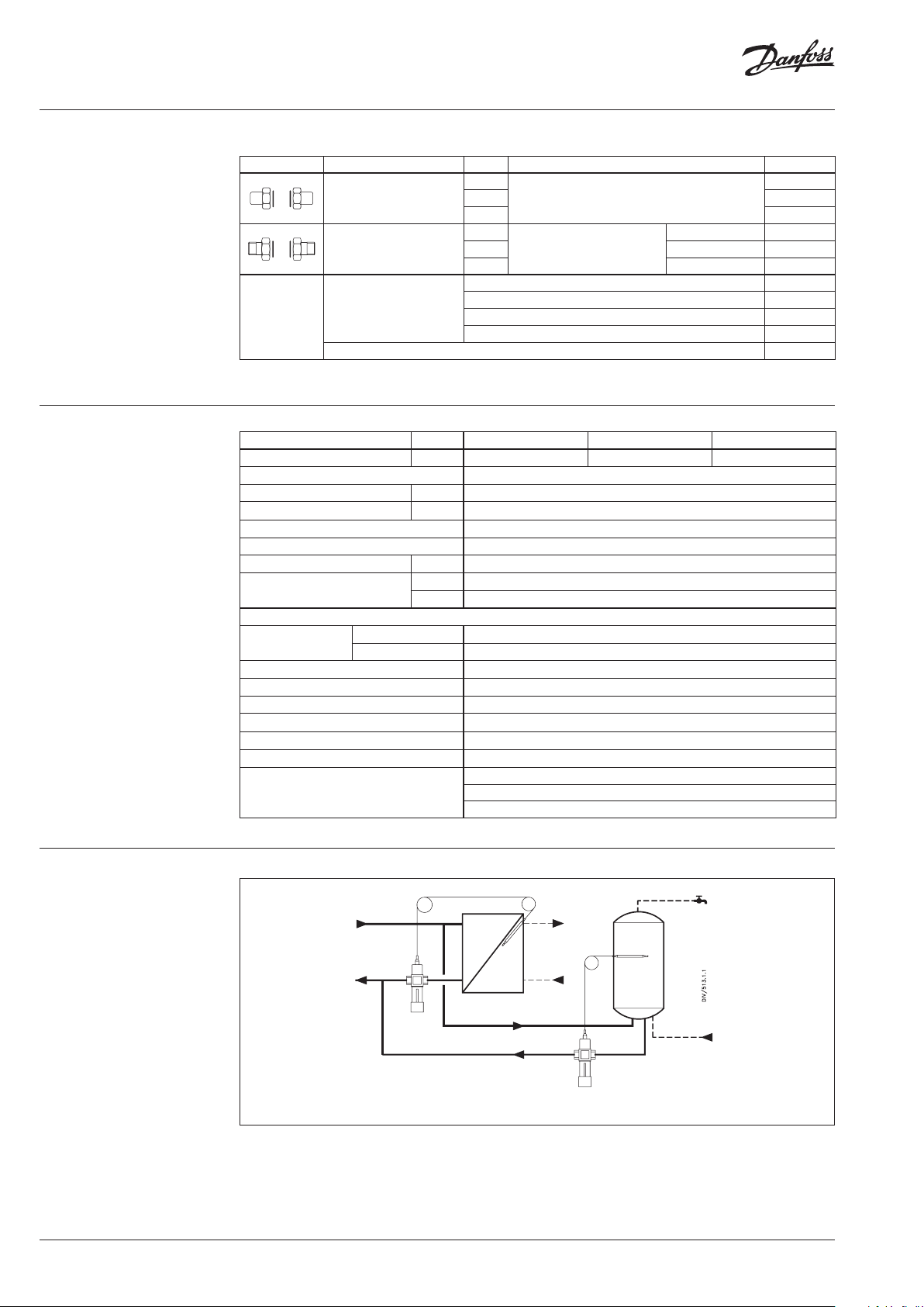
Application principle
Slow control system, setting range 30 …100°C
Fast control system, setting range 0 … 30°C/20 … 60°C
2 | VD.JK.Z4.02 © Danfoss | 2018.04
Data sheet Temperature controller AVTB (PN 16)
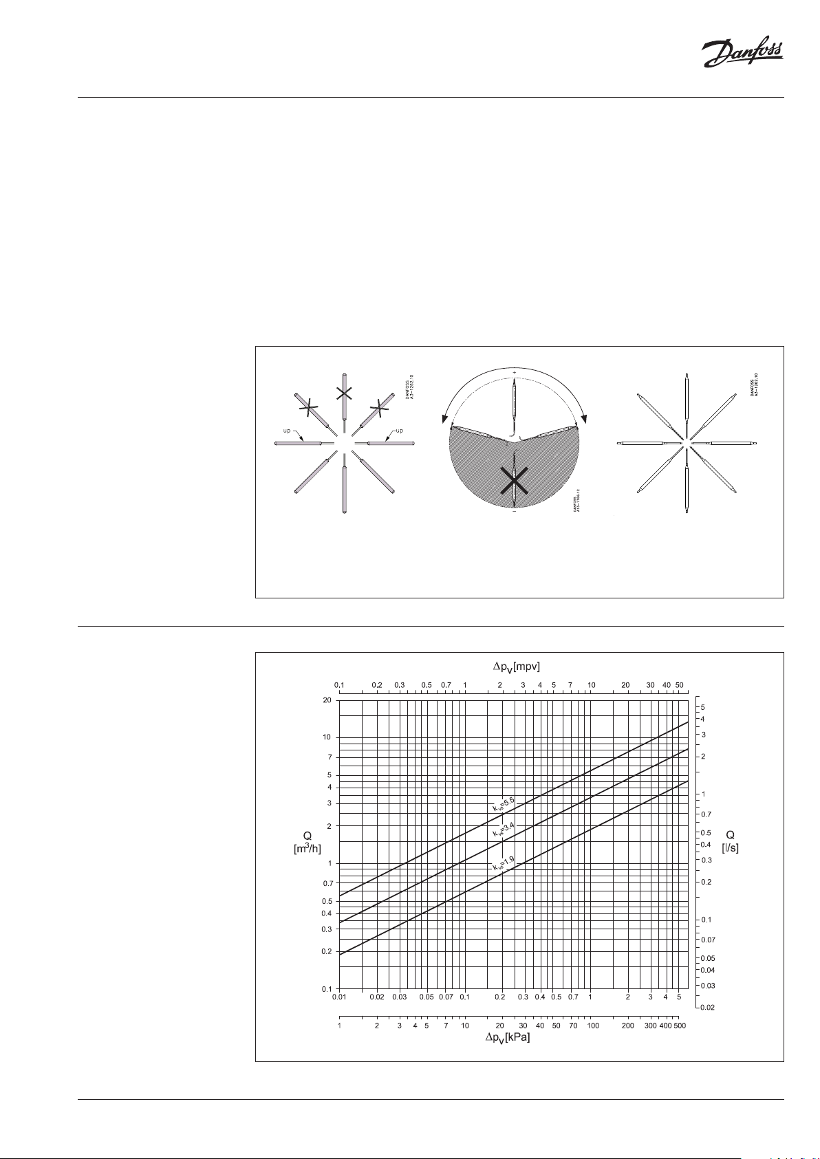
Installation positions Temperature controller
The controller can be installed in any position,
with flow in the direction of the cast-in arrow.
AVTB 20 … 60 must always be installed in the
return line (sensor warmer than valve).
If AVTB 20 … 60 has been installed in the return
line from a service water heat exchanger (where
for certain periods the return temperature
approaches the sensor temperature) the
installation of insulation disk is recommended
(003N4022).
Insulation disk is factory mounted
on the product.
Temperature sensor
AVTB 0 … 30 and 30 …100 can be installed either
in flow or in return line.
With AVTB 30 … 100, if temperature variations
of more than 20°C occur at the valve, insulation
disk (003N4022) must be installed between
thermostatic actuator and valve body.
o
f
r
r
m
e
a
p
t
s
e
B
n
c
e
Sizing
Sensor Ø 18 × 210 mm
2)
Sensor Ø 9.5 × 180 mm1) Sensor Ø 9.5 × 150 mm
(AVTB 0 … 30 °C) (AVTB 20 … 60 °C) (AVTB 30 … 100 °C)
1)
The sensor is to be m ounted where the system temp erature is warmer than the temp erature in the valve body
2)
The sensor can be m ounted where the system temp erature is either warmer or col der than the temperature in th e valve body
2)
VD.JK.Z4.02 | 3© Danfoss | 2018.04
Data sheet Temperature controller AVTB (PN 16)
hm 1,3
20
0,8631
3
hm 1,0
1,7
3,1
p
Q
k
3
v
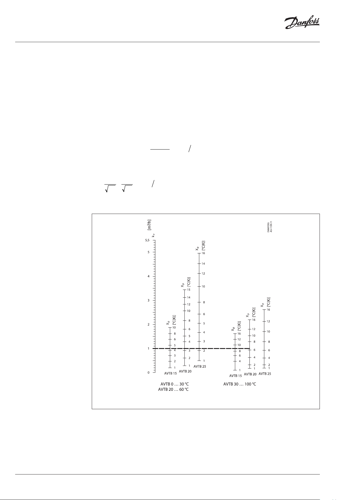
Sizing (continuous) Temperature range and P-band
Example
Hot water temperature control in hot water
tanks.
Primary medium: Water
Given:
Load: 31 kW (26500 kcal/h)
Primary temperature
drop Δt: 20 K
Differential pressure
Δp across the valve: 1.7 bar
Max. hot water
temperature: 55°C
Water volume Q:
Calculated kv value is 1m3/h.
From this value on the kV scale in the AVTB
diagram, take a line horizontally to intersect
the columns for recommended sizing range.
Select the smallest possible valve, here an AVTB
15. A temperature range of 30 …100°C can be
assumed as suitable for this example.
The P-band (XP) and final temperature range
can also be read from the AVTB diagram. The
required closing temperature can be read from
the scale for the valve selected. However, there
are two temperature ranges that meet the
requirement for a closing temperature of 55°C.
XP is 9 K for the range 30 …100°C, which means
that the controller will yield the calculated
capacity at a sensor temperature of 55°C minus 9
K = 46°C. For the range 20 … 60°C XP = 4 K. This
Required:
The correct valve size
means that the controller will yield the calculated
capacity at 55°C minus 4 K = 51°C.
To ensure the most stable control an AVTB 15
with a range 30 … 100 °C should be chosen. The
water in the hot water tank will reach the closing
temperature (55°C) only when there has been no
hot water demand for some time.
AVTB diagram to determine valve size, temperature range and proportional band (XP).
Note: The values stated are mean values
4 | VD.JK.Z4.02 © Danfoss | 2018.04
Data sheet Temperature controller AVTB (PN 16)
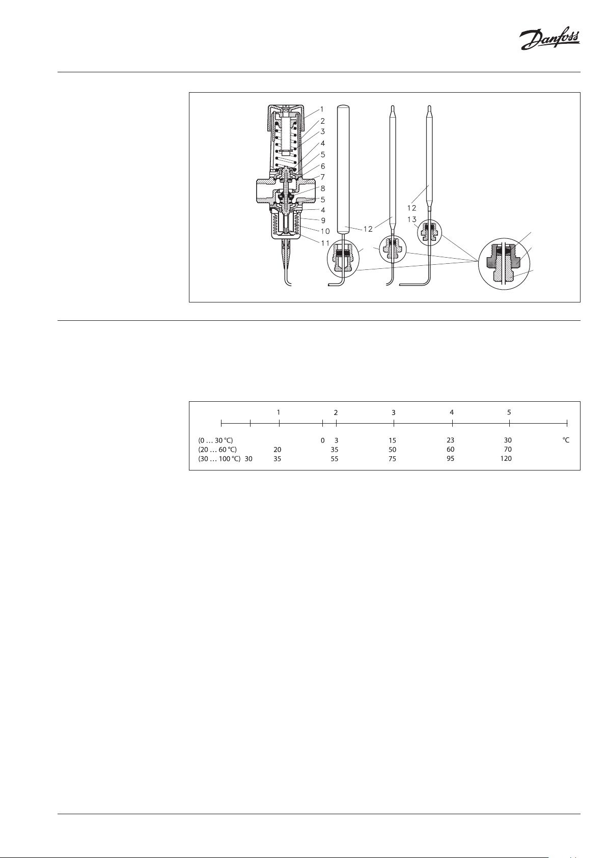
Design
1. Handle for temperature
setting
2. Spring housing
3. Setting spring
4. O-ring
5. Diaphragm
6. Spindle
7. Valve body
8. Valve cone
9. Bellows
10. Bellows stop
11. Pres sure stem
12. Temperature sensor
13. Sensor stuffing box
14.
Housing of sensor stuffing
box
15. Gasket of sensor stuffing box
16. Sealing bolt of sensor
stuffing box
Settings Temperature setting
Relation between scale numbers 1-5 and the
closing temperature.
15
13
14
16
The values given are approximate.
Scale settin g
Closing temperature
VD.JK.Z4.02 | 5© Danfoss | 2018.04
Data sheet Temperature controller AVTB (PN 16)
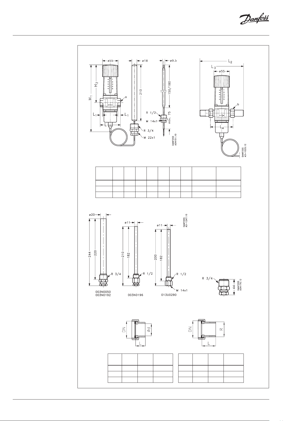
Dimensions
AVTB with internal thread AVTB with external thread
H
H
1
Typ e
AV TB 15 217 133 72 14 141 149 75 Rp ½ G ¾A
AVT B 20 217 133 90 16 154 164 80 Rp ¾ G 1A
AVT B 25 227 138 95 19 16 8 167 83 Rp 1 G 1¼ A
mm
2
mmLmm
L
1
mmL2mmL3mmL4mm
a
IS O 7/1
(int. thread)
b
ISO 228/1
(ext. thread)
Immersion pockets Sensor stuffing box
Weld-on tailpieces External thread tailpieces
G Ød L Weight
(mm) (mm) (mm) (kg)
15 15 35 0.18
20 20 40 0.26
25 27 40 0.38
G R L Weight
(“) (“) (mm) (kg)
¾ ½ 25.5 0 .17
1 ¾ 2 7. 5 0.27
1 ¼ 1 32.5 0.45
6 | VD.JK.Z4.02 © Danfoss | 2018.04

Data sheet Temperature controller AVTB (PN 16)
VD.JK.Z4.02 | 7© Danfoss | 2018.04

Danfos
produc
Al
Danfoss A/S
Heating Segment
Data sheet Temperature controller AVTB (PN 16)
s can accept no responsibility for possible errors in catalogues, brochures and o ther printed material. Danfoss reserves the right to alter its pro ducts without notice. This also applies to
ts already on order provided that such alterations can be m ade without subsequential changes being necessary in specications already agreed.
l trademarks in this material are property of the r espective companies. Danfoss and all Danfoss logotypes are trademark s of Danfoss A/S. All rights reserved.
• heating.danfoss.com • +45 7488 2222 • E-Mail: heating@danfoss.com
© Danfoss | DHS-SRMT/SI | 2018.048 | VD.JK.Z4.02
 Loading...