

Page 1

Operating Guide
AME 25, AME 35
ENGLISH
DANSK
DEUTSCH
FRANÇAIS
ESPAÑOL
SUOMI
NEDERLANDS
POLSKI
РУССКИЙ
ROMÂNĂ
AME 25, AME 35 +
Adapter (0 6 5Z 0311) +
VRB 2, VRG 2 (D N 15-50)
AME 25, AME 35 www.danfoss.com Page 5
AME 25, AME 35 www.danfoss.dk Side 6
AME 25, AME 35 www.danfoss.de Seite 7
AME 25, AME 35 www.danfoss.fr Page 8
AME 25, AME 35 www.danfoss.es Página 9
AME 25, AME 35
AME 25, AME 35 www.danfoss.nl Bladzijde 11
AME 25, AME 35
AME 25, AME 35
AME 25, AME 35 www.incalzire.danfoss.com Pagina 14
AME 25, AME 35 +
Adapter (0 6 5Z 0311) +
VRB 3, VR3 2 (D N 15-50)
AME 25, AME 35 +
Adapter (0 6 5Z 0311) +
VF 2, VL 2 (DN 15-50)
www.danfoss.fi Sivu 10
www.danfoss.pl Strona 12
www.danfoss.ru Страница 13
AME 25, AME 35 +
Adapter (0 6 5Z 0311) +
VF 3, VL 3 (DN 15-50)
AME 25, AME 35 +
VFS 2 (DN 15-50)
中文
© Danfoss | 2016.11
AME 25, AME 35 www.danfoss.com.cn 第 16 页
EI.LF.M1.2V | 1
Page 2

AME 25, AME 35
=
AUTO
➊
MAINTENANCE
①
FREE
5-95 % RH
no condensing
②
4×
or
❸
=
4 – 6 mm × 1 mm T 10 2 / 4 mm
③
③
❹
❷
4×
➊
BLUE
RED
B
A
A B
❷
T
≤150 ° C T
max
=150 … 200° C
max
≈5°
065Z 7548
≈5°
2 | © Danfoss | 2016.11
EI.LF.M1.2V
Page 3

AME 25, AME 35
❸
Wiring for modulating mode
Proportional 3 point/ RL
Wiring fo r 3-point flo ating mode
Controll er with relay outpu t
SN 0 V Neutral
SP 24 VAC Power supply
Y
1
3
X 0(2) -10 V Output
0(2)-10 V
0(4) -20 mA
0 V Input
Input
Proportional 3 point/ RL
Wiring fo r 3-point flo ating mode
Controll er with triacs out put
Proportional 3 point/ RL
SN 0 V Neutral
SP 24 VAC Pow er supply
1
24 VAC Input
3
X 0(2)-10 VDC Output
SN
SP
1
3
24 VAC Neutral
0 V Power suppl y
24 VAC Input
EI.LF.M1.2V
X 0(2)-10 V DC Output
© Danfoss | 2016.11 | 3
Page 4

AME 25, AME 35
❹
⑦
④
②①
⑤
⑧
③
⑥
⑨
❺
⑩
155
179
16
47, 5
min . 160
83
EI.LF.M1.2V
© Danfoss | 2016.11 | 4
Page 5

AME 25, AME 35
ClampXO
O
OOO
YokeXO
O
OOO
ENGLISH
Safety Note
To avoid injury of persons and
damages to the device, it is absolutely
instructions carefully.
Necessary assembly, start-up, and maintenance
work must be performed by qualified and
authorized personnel only.
Please comply with the instructions of the
system manufacturer or system operator.
Disposal instruction
Mounting
Fix the actuator on the valve ❶
Admissible Installation Positions ❷
Wiring ❸
Control signal
Control signal from the controller must be
connected to terminals Y (input signal) and SN
(common) on the AME printed board.
Output signal
Output signal from the terminal X can be used
for indication of the current position. Range
depends on the DIP switch settings.
Supply voltage
Supply voltage (24 V~ –15 to +10 %, 50 Hz) must
be connected to the terminals SN and SP.
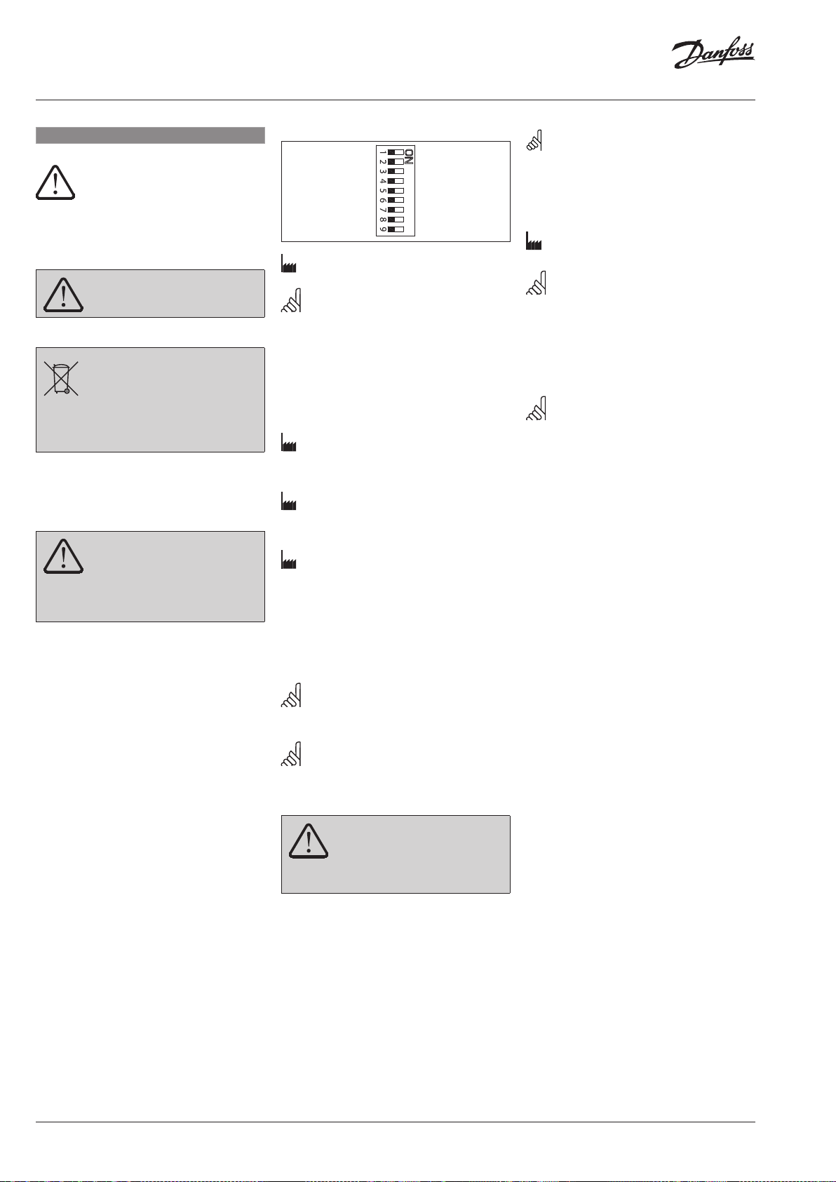
DIP switch settings ❹
necessary to read and observe these
Do not remove the cover before th e
power supply is ful ly switched off.
This product shou ld be dismantled
and its components so rted, if possible,
in various groups befo re recycling or
disposal.
Always follow the local d isposal regulations.
Do not touch anythin g on the PCB!
Switch off the power lin e before wire
the actuator! Lethal voltage!
Wire the actuator according to the wi ring
diagram.
U I
2 V_---V 0 V_---V
Direct Inverse
--- S equential
0(2) V_5(6) V 5(6) V_10 V
Proportional 3 point/RL
LOG. fl ow L IN. flow
100 % k
VS
Reset Reset
RED. k
VS
Factory settings:
ALL switches are on OFF position! ❹①
Note: All combinations of DIP switches are
allowed. All functions that are selected are added
consecutively. There is only one logic override of
functionalities i.e. the switch No.6 Propor tional/3
point, which sets actuator to ignore control signal
and works as a “simple” 3-point actuator.
SW1: U/I ❹②
Factory settings:
Voltage control signal (0-10 V).
SW2: 2-10 V/0-10 V ❹③
Factory settings:
2-10 V.
SW3: Direct/Inverse ❹④
Factory settings:
DIRECT
SW4:---/Sequential ❹⑤
Two actuators can be set to work parallel with
one control signal. If the SEQUENTIAL is set than
an actuator respowwnds to split control signal
(see 0(2)-5(6) V/5(6)-10 V).
Note: This combination works in combination
with switch No.5: 0(2)-5(6) V/5(6)-10 V
SW5: 0(2)-5(6) V/5(6)-10 V ❹⑥
Note: This function is available if switch No.4:
---/Sequential is set.
SW6: Proportional/3 point ❹⑦
Actuator needs to pe rform Self
stroking prior chan ging DIP 6 to ON.
Output signal dep ends on DIP 2, 3&5
setting.
Actuator can operate in modulating (DIP 6 to
OFF) or in “simple” 3-point mode, if the 3-point
function is selected (DIP 6 to ON).
Connect power supply on terminals SN and SP
terminals.
Factory set DIP 6 to OFF for operating actuator
in Modulating mode.
Actuator’s stem will run to its totally extended
or retracted position by bridging SN signal to
terminals 1 or 3 and will remain in this positron
as long as potential is present.
Set DIP 6 to ON for operating actuator in 3 point
mode.
Look carefully wiring diagram as wiring is
different for controllers with triac output (ECL)
in comparison to controllers with relay output.
Return signal X indicates the correct position.
Note: If 3 point function is selected actuator
does not respond to any control signal on port Y.
It only rises and lowers spindle if power is supplied
on port 1 or 3.
SW 7: LOG. flow/LIN. flow ❹⑧
Factory setting is:
LOG. Flow (characteristic of valve is unchanged)
Note: If this function is used in combination
with non-logarithmic valves the characteristic
of motorised valve will be anti-logarithm of
valve’s characteristic (e.g. valve with linear
characteristic will be transformed to quick open
characteristic).
SW 8: 100% KVS/RED. KVS ❹⑨
Note: This function works proper only with
logarithmic (equal percentage) valves.
SW9: Reset ❹⑧
After the actuator has been connected to
power supply, the actuator will start the
self-adjustment procedure. The indicator LED
flashes until self adjustment is finished. The
duration depends on the spindle travel and will
normally last a few minutes. The stroke length
of the valve is stored in the memory after self
adjustment has been completed. To restart
self adjustment, change the position of RESET
switch (switch No.9). If the supply voltage is
switched off or falls below 80 % in more than
0.1 s, the current valve position will be stored
in the memory and all data remain saved in the
memory also after a power supply cut-out.
Function test
The indicator light shows whether the
positioner is in operation or not. Moreover, the
indicator shows the control status and faults.
Constant light
- normal operation
No light
- no operation or no power supply
Intermittent light (1 Hz)
- self adjusting-mode
Intermittent light (3 Hz):
- power supply too low
- insufficient valve stroke (<20 s)
- end-position cannot be reached.
Dimensions ➎
Part Name
Housing X O O O O O
Bushings X O O O O O
O: Indica tes that this hazar dous substance con tained in all of the h omogeneous ma terial for this par t is below the limi t requirement in GB /T 26572;
X: Indica tes that this hazar dous substance co ntained in at least o ne of the homogen eous material fo r this part is above th e limit requirem ent in GB/T 26572;
Lead (P b) Mercur y (Hg) Cadmium (Cd) Hexavalent Chromium (Cr(VI)) Polybrominated biphenyls (PBB) Polybrominated diphenyl ethers (PBDE)
EI.LF.M1.2V
Hazardous Substances Table
© Danfoss | 2016.11 | 5
Page 6

AME 25, AME 35
DANSK
Sikkerhedsbestemmelser
For at undgå skader på personer og
udstyr, er det absolut nødvendigt at
gennemlæse følgende vejledning.
Montering, opstart og vedligeholdelse må
kun foretages af kvalificeret og autoriseret
personale.
Følg fabrikantens eller operatørens
instruktioner.
Fjern ikke dækslet , før
strømforsyning en er helt koblet fra.
Bortskaffelsesinstruktion
Dette produk t skal, om muligt,
adskilles og sor teres i dets forskellige
materialegrupper, før det genbruges
eller bortskaffes.
Følg altid de lokale regulati ver for bortskaffelse .
Montering
Fastgør AME 25, AME 35 på ventilen ❶
Tilladelige installationspositioner ❷.
Elektrisk tilslutning ❸
Rør ikke ved PCB!
Sluk for strømmen ind en elektrisk
tilslutning af motoren! Kan være
livsfarlig!
Tilslut motoren iht. ledningsdiagrammet.
* El-tilslutning for modulerende styring
(Wiring for modulating mode)
** El-tilslutning for 3-punkts styring med
relæudgang i regulator (Wiring for 3-point
floating mode Controller with relay output)
*** El-tilslutning for 3-punkts st yring med
triacudgang i regulator (Wiring for 3-p oint
floatig mode Controller with triacs output)
Styresignal
Styresignalet fra regulatoren skal tilsluttes
terminal Y (indgangssignal) og SN (fælles) på
AME´s klemrække.
Udgangssignal
Udgangssignal fra terminal X kan anvendes til
indikering af aktuel position.
Området afhænger af DIP kontakternes
indstilling.
Forsyningsspænding
Forsyningsspændingen (24 V~ –15/+10 %, 50
Hz) skal tilsluttes klemme SN og SP.
Indstilling af DIP kontakter ❹
U I
2 V_---V 0 V_---V
Direkte Sekventiel
---
0(2) V_5(6) V 5(6) V_10 V
Omvendt 3-punkt/RL
LOG. fl ow L IN. flow
100 % K
VS
Reset Nulstil
Fabriksindstilling:
Alle kontakter er I OFF position! ❹①
Bemærk: Alle kombinationer af
kontaktindstillinger er tilladelige. Alle
funktionsvalg er tilføjet en efter en. Der er kun
en logisk overskridelse af funktionaliteten:
Kontakt Nr. 6 Proportional/3-punkt styring,
som sætter ak tuatoren i stand til at ignorere
reguleringssignalet og arbejde som en ”simpel”
3-punkt motor.
SW1: U/I ❹②
Fabriksindstilling
Spændingssignal (0-10 V).
SW2: 2-10 V/0-10 V ❹③
Fabriksindstilling:
2-10 V.
SW3: Direkte/Indirekte ❹④
Fabriksindstilling:
DIREKTE
SW4: ---/Sekvens ❹⑤
To aktuatorer kan arbejde parallelt med et
reguleringssignal. I SEKVENS indstilling reagerer
aktuatoren på delt styresignal (se 0(2)-5(6)
V/5(6)-10 V).
Bemærk: Denne kombination arbejder
sammen med kontakt Nr. 5: 0(2)-5(6) V/5(6)-10 V
SW5: 0(2)-5(6) V/5(6)-10 V ❹⑥
Bemærk: Denne funktion er tilgængelig hvis
kontakt Nr. 4:---/ekvens er indstillet.
SW6: Proportional/3-punkt ❹⑦
Når DIP 6 er på Ak tuator skal udføre
automatiske kalibrering foru d at
DIP-6.
Udgangssignal afhæ nger af DIP-2, 3 &5
Indstilling.
Aktuator kan køre i modulerende (DIP 6 til OFF)
eller i “simple” 3-punkts funktion, hvis 3-punkt
funktionen er valgt (DIP 6 til ON).
Tilslutte forsyningsspænding på klemme SN og
SP terminaler.
Fabriksindstillet DIP 6 til OFF for at drive
Aktuator i modulerende tilstand.
Aktuator’s stem løber frem til dens fuldt
udstrakt eller tilbagetrukne position ved at
bygge bro mellem SN signal til klemme 1
eller 3 og forbliver i denne positron så længe
potentiale er til stede.
Indstil DIP 6 på ON for Aktuator kører i 3 punkts
funktion.
Proportional
Red. K
VS
Se nøje ledningsdiagram som ledningsføring er
forskellig for regulatorer med triacudgang (ECL)
i caparison til regulatorer med relæudgang.
Bemærk: Hvis 3-punkt funk tionen er valgt,
reagerer aktuatoren ikke på signaler på klemme Y.
Motorspindelen bevæger sig kun opad eller nedad
ved signaler på klemme 1 eller 3.
SW 7: LOG. flow/LIN. flow ❹⑧
Fabriksindstilling:
LOG.flow (ventilkarakteristikken er uændret).
Bemærk: Anvendes denne funktion i
kombination med ikke logaritmiske ventiler, vil
karakteristikken for motorventilen blive modsat
logaritmisk i forhold til ventilkarakteristikken
(d.v.s. en ventil med lineær karakteristik vil blive
transformeret til hurtig åben karakteristik).
SW 8: 100% KVS/RED. KVS ❹⑨
Bemærk: denne funktion virker kun ved
logaritmiske ventiler.
SW9: Reset ❹⑧
Efter tilslutning af forsyningsspænding,
vil aktuatoren starte en selvjusterings
procedure. LED indikatoren blinker indtil
selvjusteringen er færdig. Varigheden afhænger
af spindelvandringen og tager normalt
nogle få minutter. Ventilens spindelvandring
lagres i hukommelsen efter selvjusteringen
er færdig. For at starte selvjustering, skiftes
positionen af RESET kontakten (kontakt Nr. 9).
Hvis forsyningsspændingen svigter eller falder
til under 80 % i mere end 0,1 sekund, vil den
aktuelle ventilposition lagres i hukommelsen
og alle data bliver bevaret i hukommelsen, også
efter at forsyningsspændingen afbrydes.
Funktions test
Lysdioden indikerer, om aktuatoren er i drift,
ligesom den viser driftsstatus og eventuelle fejl.
Konstant lys
- normal drift
Intet lys
- ikke i drift, ingen strømforsyning
Interval blink (1 Hz)
- selvjusteringsmodul
Interval blink (3 Hz)
- strømforsyning for lav
- ventil slaglængde utilstrækkelig
- endestilling kan ikke nås
Mål ➎
6 | © Danfoss | 2016.11
EI.LF.M1.2V
Page 7

AME 25, AME 35
DEUTSCH
Sicherheitshinweise
Um Verletzungen an Personen und
Schäden am Gerät zu vermeiden, ist
diese Anleitung unbedingt zu
beachten.
Montage, Inbetriebnahme und
Wartungsarbeiten dürfen nur von sachkundigen
und autorisierten Personen durchgeführt
werden.
Die Vorgaben des Anlagenherstellers und
Anlagenbetreibers sind zu beachten.
Entfernen Sie die Ab deckung nicht,
bevor die Stromversorgung komplett
ausgeschaltet ist.
Anweisung zur Entsorgung
Dieses Produkt sollte ausgebaut und
in dessen Bestandteile zerlegt werden.
Sortieren Sie die einzelnen
Bestandteile entsprechend der
Entsorgungsgruppen zur Wiederverwertung
oder Entsorgung.
Beachten sie dabei immer die lokalen
Entsorgungsrichtlinien.
Montage
AME 25, AME 35 am Ventil ansetzen ❶
Zulässige Einbaulagen ❷.
Elektrischer Anschluß ❸
Bitte die Platine nicht dire kt
berühren!
Trennen Sie das Netzkabel vor
der Verdrahtung des Stellantriebs! Tödliche
Spannung!
Schließen Sie den Stellantrieb gemäß
dem Verdrahtungsplan an.
* Verdrahtung für die modulierende
Regelung (Wiring for modulating mode)
** Verdrahtung für die 3-Punkt-Regelung mit
Relaisausgang (Wiring for 3-point f loating
mode Controller with relay output)
*** Verdrahtung für die 3-Punkt-Regelung mit
Triac-Ausgang (Wiring for 3-point floatig
mode Controller with triacs output)
Steuersignal
Das Steuersignal des Reglers ist an Klemme
Y (Eingangssignal) und Klemme SN
(Sammelklemme) an der AME-Printplatte
anzuschließen.
Ausgangssignal
Das Ausgangssignal von Klemme X kann zur
Anzeige der aktuellen Position benutzt werden.
Der Bereich hängt von der Brücke ab.
Spannungsversorgung
Die Spannungsversorgung (24 V~ –15 bis +10 %,
50 Hz) ist an Klemme SN und SP anzuschließen.
Einstellung der DIP Brücke ❹
U I
2 V_---V 0 V_---V
Direkte Sekventiel
---
0(2) V_5(6) V 5(6) V_10 V
Omvendt 3-punkt/RL
LOG. fl ow L IN. flow
100 % K
VS
Reset Nulstil
Werkseinstellung:
ALLE Schalter sind in der Position OFF! ❹①
Bemerkung: Alle Kombinationen von DIP
Schalter sind erlaubt. Gewählte Funktionen sind
hintereinandergelegt. Es gibt nur eine logische
Umsteuerung der Funktionen: Brücke Nr.6
proportional/3-Punkt. Dadurch wird der Antrieb so
umgeschaltet, dass das Signal ignoriert wird und
arbeitet als “üblicher” 3-Punkt Anrieb.
SW1: U/I ❹②
Werkseinstellung:
Spannungsregelsignal (0-10V).
SW2: 2-10 V/0-10 V ❹③
Werkseinstellung:
2-10 V .
SW3: Direct/Inverse ❹④
Werkseinstellung:
DIRECT
SW4: ---/Sequentiell ❹⑤
Zwei Antriebe können parallel mit einem
Steuersignal arbeiten. Bei der Einstellung
SEQUENTIAL Antrieb reagiert auf geteilten
Steuersignal (sehe 0(2)-5(6) V/5(6)-10V).
Bemerkung: Diese Kombination funktioniert
mit dem Schalter No.5: 0(2)-5(6) V/5(6)-10 V
SW5: 0(2)- 5(6) V/5(6)-10 V ❹⑥
Bemerkung: Diese Funktion ist wirksam,
wenn der Schalter No.4: --- /Sequentiell eingestellt
ist.
SW6: Proportionäl/3-Punkt ❹⑦
Wenn der DIP- 6 ist auf Stellmotor
muss Ventilhub vor dem Ändern der
DIP 6 auf ON.
Ausgangssignal ist abhängi g von DIP-2, 3 &5
Einstellung.
Stellmotor kann bei jeglichen arbeiten
modulierend (DIP-6, um AUS) oder in “einfacher”
3-Punkt, wenn die 3-Punkt Funktion ausgewählt
ist (DIP-6, um auf).
Anschließen Spannungsversorgung an den
Klemmen SN und SP-Klemmen.
Werkseitig eingestellte DIP 6 auf OFF für den
Betrieb in Stellmotor modulierend Modus.
Stellmotor Antriebsstange ausgeführt
werden soll, der vollkommen erweitert oder
eingefahrener Stellung Audio-Bestandskunden
SN Signal an den Klemmen 1 oder 3 und bleibt
in diesem Elektron-Positron -so lange wie
Potenzial vorhanden ist.
Stellen Sie DIP-Schalter 6 auf EIN für den
Stellmotor in 3 Punkt.
Proportional
Red. K
VS
Bitte schauen Sie Schaltplan als Verdrahtung
ist anders für Regler mit Tricausgang (ECL) in
Prachtdecke durch Controller mit Relaisausgang.
BEMERKUNG: Wenn die 3-Punkt Funktion
gewählt wird, reagier t der Antrieb nicht auf
irgendwelche der Steuersignale Y Klemme. Der
Antrieb bewegt die Motorenspindel nach oben
oder nach unten bei dem Steuersignal auf Klemme
1 oder 3.
SW7: LOG. flow/LIN. flow ❹⑧
Werkseinstellung:
LOG. Flow (Ventilcharakteristik bleibt
unverändert).
Bemerkung: falls diese Funktion mit dem
nicht logarithmischen Ventil verwendet wird,
übernimmt der Antrieb die Anti-Logarithem der
Ventilcharakteristik. (Ventil mit linearer Kennlinie
wird in die Kennlinie umgewandelt).
SW 8: 100% KVS/RED. KVS ❹⑨
Bemerkung: diese Funktion arbeitet richtig
nur mit logarithmischen (gleichprozentigen)
Ventilen.
SW9: Reset ❹⑧
Nach Einschalten der Stromversorgung startet
der Regelantrieb den Selbstanpassungsvorgang.
Die Leuchtdiode blinkt, bis die Anpassung
abgeschlossen ist. Dies dauert normalerweise
einige Minuten, abhängig von der Distanz
der Spindelbewegung. Die Hublänge
des Ventils wird nach abgeschlossener
Selbstanpassung im Speicher registriert. Der
Selbstanpassungsvorgang kann durch Drücken
der RESET-Taste wiederholt werden (Schalter No.
9). Bei Ausfall der Versorgungsspannung - oder
beim Absinken auf einen Wert kleiner 80 % länger als 0,1 s, wird die aktuelle Ventilposition
im Speicher gespeichert. Alle Daten sind also
auch im Falle einer Stromunterbrechung
gesichert.
Funktionstest
Die Leuchtdiode zeigt den Motorbetrieb, den
Betriebszustand und eventuelle Fehler an.
Dauerlicht
- normaler Betrieb
Kein Licht
- nicht in Betrieb oder keine
Stromversorgung
Blinklicht (1 Hz)
- Selbstanpassungsmodus
Blinklicht (3 Hz)
- Versorgungsspannung zu niedrig
- Ventilhublänge ungenügend (<20 s)
- Endposition nicht erreichbar.
Abmessungen ➎
EI.LF.M1.2V
© Danfoss | 2016.11 | 7
Page 8

AME 25, AME 35
FRANÇAIS
Sécurité
Pour éviter des blessures des
personnes et des dégâts au dispositif,
il est absolument nécessaire de lire
attentivement et de respecter ces instructions.
Le montage, la mise en marche et toute
opération de maintenance doivent être
effectués par un service ou une personne de
qualification.
Suivre les instructions du fabricant du système
ou de son service.
Ne pas retirer le capot avant d ’avoir
totalement coupé l’alimentation.
Indications de mise au rebus
Ce produit peut être dém onté et tous
ses composants classés si possible e n
différentes catégor ies en vue de leur
recyclage ou dest ruction
Dans tous les cas , suivre la législatio n locale de
mise au rebus.
Montage
Fixer l’AME 25, AME 35 sur la vanne ❶
Orientations de montage ❷
Branchement éléctrique ❸
Ne pas toucher la car te de circuit
imprimé !
Couper l’alimentation avant de
raccorder l’actionneur ! Dang er de mort !
Raccorder l’actionneur confo rmément au
schéma de branchement électrique.
* Raccordement pour le mode modulant
(Wiring for modulating mode)
** Raccordement pour mode flottant 3 points -
Régulateur avec sortie relais (Wiring for 3-point
floating mode Controller with relay output)
*** Raccordement pour mode flottant 3 points -
Régulateur avec sortie triac (Wiring for 3-point
floatig mode Controller with triacs output)
Signal de commande
Le signal du régulateur doit être branché sur
la borne Y (signal d’entrée) et la borne SN
(commun) sur la carte imprimée de l’AME.
Signal de sortie
Le signal de sortie de la borne X peut servir pour
indiquer la position actuelle. La zone dépend
des réglages du sélecteur de fonction DIP.
Tension d’alimentation
La tension d’alimentation (24 V~ –15/+10 %, 50
Hz) doit être branchée aux bornes SN et SP.
Réglages du sélecteur de fonction DIP ❹
U I
2 V_---V 0 V_---V
Direct Inverse
--- Séquentiel
0(2) V_5(6) V 5(6) V_10 V
Proportionnel 3 points/RL
Débit LO G. Débit LIN.
100 % K
VS
Reset Reset
Réglage d’usine:
TOUTES les commandes sont en position
ARRÊT! ❹①
Remarque: Toutes les combinaisons
des commandes DIP sont possibles. Toutes les
fonctions sélectionnées sont ajoutées l’une à
l’autre. Il y a seulement un pontage logique des
fonctions: commande 6 Proportionnel/ 3 points
qui fait le moteur ignorer le signal de commande et
fonctionne comme un »simple« 3-points moteur.
SW1: U/I ❹②
Réglage de l’usine:
Le signal de commande de tension (0 -10 V).
SW2: 2-10 V/0-10 V ❹③
Réglage de l’usine:
2-10 V.
SW3: Direct/Inverse ❹④
Réglage de l’usine:
DIRECT
SW4: ---/Séquentiel ❹⑤
Deux moteurs peuvent être réglés de telle
manière qu’ils fonctionnent parallèlement
avec un signal de commande. Si la fonction
SÉQUENTIEL est réglée, le moteur répond au
signal de commande »split«
(voir 0(2)-5(6) V/5(6)-10 V).
Remarque: Cette combinaison fonctionne
en combinaison avec la commande 5: 0(2)-5(6)
V/5(6) -10V.
SW5: 0(2)-5(6) V/5(6)-10V ❹⑥
Remarque: Cette fonction est disponible, si la
commande 4: ---/Séquentiel est réglée.
SW6: Proportionnel/3 points ❹⑦
Lorsque le DIP 6 est SUR Act uateur
doit exécuter autorég ulation avant le
DIP en perpét uelle évolution 6 sur
ON.
Signal de sortie dé pend du commutateur DIP 2,
3 et 5 Réglage.
Actuateur permet de fonctionner en modulant
(DIP 6 sur OFF) ou dans “simple” 3-points mode,
si la fonction 3 points est sélectionnée (DIP 6
sur ON).
Alimentation pour alimenter les bornes SN et SP
les bornes.
Réglage d’usine DIP 6 sur OFF pour la mise en
œuvre d’Actuateur en mode modulant.
Actuateur tige continue de fonctionner à sa
position rétractée en établissant totalement
étendue ou signal de SN à la borne 1 ou 3
et resteront dans cette positon tant que le
potentiel est présent.
Red. K
VS
Régler le DIP 6 sur ON pour l’exploitation
Actuateur en mode 3 points.
Schéma de raccordement en tant que regarder
attentivement câblage est différente pour
les régulateurs avec sortie triac (ECL) en
comparaison avec les régulateurs avec sortie de
relais.
REMARQUE: Si la fonction 3 points est
sélectionnée, le moteur ne répond à aucun signal
de commande sur la borne Y. Cette fonction
seulement déplace la broche vers le haut et vers
le bas, s’il y a de l’alimentation en courant sur les
bornes 1 et 3.
SW7: Débit LOG./ débit LIN. ❹⑧
Réglage de l’usine:
débit LOG. (caractéristique de la vanne ne change
pas).
Remarque: Si cette fonction est
utilisée en combinaison avec les vannes
non-logarithmiques, la caractéristique de la
vanne motorisée sera l’anti-logarithme de la
caractéristique de la vanne (p.e. une vanne avec
la caractéristique linéaire sera transformée en
caractéristique »rapidement ouverte«).
SW 8: 100% KVS/RED. KVS ❹⑨
Remarque:
Cela ne fonctionne proprement qu’avec les vannes
logarithmiques (même pourcentage).
SW9: Exploitation ❹⑧
Une fois alimenté, le moteur commence un
procédé d’auto-réglage. La diode lumineuse
clignote jusqu’à ce que l’auto-réglage soit
términé. Cela dure normalement env. 2 minutes,
suivant le déplacement de la broche. La course
de la vanne est conservée en mémoire à la fin
de l’auto-réglage. Le changement de position
de la commande R. À Z. (commande 9) fera
redémarrer l’auto-réglage. Si l’alimentation est
interrompue – ou chute à une valeur inférieure
à 80 % - pendant plus de 0,1 sec., la position
actuelle de la vanne est mémorisée. Toutes les
données seront donc mémorisées, même en cas
de coupure de courant.
Test de fonction
La diode lumineuse indique que le moteur est
en fonction. Elle indique aussi l’état de marche
et les erreurs éventuelles.
Lumière permanente
- marche normale
Pas de lumière
- fonction arrêtée, pas d’alimentation
Clignotements par intervalles (1 Hz)
- mode d’auto-réglage
Clignotement par intervalles (3 Hz)
- alimentation en courant trop faible
- course de vanne insuffisante (<20 s)
- la fin de course ne peut pas être atteinte.
Dimensions ➎
8 | © Danfoss | 2016.11
EI.LF.M1.2V
Page 9

AME 25, AME 35
ESPAÑOL
Nota de seguridad
A fin de evitar lesiones personales o
daños en el dispositivo, es
absolutamente necesario leer y
respetar estrictamente estas instrucciones.
Las operaciones de montaje, puesta en
marcha y mantenimiento deben ser realizadas
únicamente por personal cualificado y
autorizado.
Por favor, respete las instrucciones del
fabricante u operador del sistema.
No retire la cubier ta antes de haber
desconectado el suministro eléctrico
por completo.
Instucciones de eliminación
Este producto deb e ser desmontado y
si es posible, sus componentes d eben
ser separados en varios gru pos antes
de su reciclado o destrucció n.
Siga siempre la regulació n local sobre
eliminación.
Montaje
Montaje del AME 25, AME 35 en la válvula ❶
Posiciones de instalación permitidas ❷
Cableado ❸
¡No toque nada en la pl aca de circuito
impreso! ¡Tensión letal!
¡Desactive la lín ea de suministro
eléctrico antes de conectar el actuador!
Conecte el actuador de acuerdo con el esquema
de cableado.
* Cableado para modo modulante
(Wiring for modulating mode)
** Cableado para modo f lotante de 3
puntos, controlador con salida para
relé (Wiring for 3-point floating mode
Controller with relay output)
*** Cableado para modo flotante de 3 puntos,
controlador con salida triacs (Wiring for 3-point
floatig mode Controller with triacs output)
Seńal de control
La seńal de control proveniente del regulador
deberá ser conectada al terminal Y (seńal de
entrada) y al terminal SN (común) en el circuito
impreso del AME.
Seńal de salida
La seńal de salida del terminal X puede usarse
para indicar la posición actual. El rango
dependerá de la configuración del interruptor
DI P.
Tensión de alimentación
La tensión de alimentación
(24 V~–15/+10 %, 50 Hz) tiene que ser conectada
a los terminales SN y SP.
Las configuarciones del interruptor
DIP ❹
U I
2 V_---V 0 V_---V
Directo Secuencial
--- Proporcional
0(2) V_5(6) V 5(6) V_10 V
Inverso 3 puntos R / L
Flujo LOG . Flu jo LIN.
100 % K
Restablecimiento
VS
Ajuste de fábrica:
Todos los interruptores tienen que estar en la
posición OFF! ❹①
Importante: Todas las combinaciones de los
interruptores están permitidas. Todas las funciones
seleccionadas serán añadidas una a la otra.
Solamente hay una sobreposición de las funciones:
el interruptor No.6 Proporcional/ 3 vías que hace
que el actuador ignore la señal y funcione como
un “sencillo” actuador de 3 vías.
SW1: U/I ❹②
Ajuste de fábrica:
señal de control de tensión (0-10 V).
SW2: 2-10 V/0-10 V ❹③
Ajuste de fábrica:
2-10 V.
SW3: Directo/Inverso ❹④
Ajuste de fábrica:
DIRECTO
SW4: ---/Secuencial ❹⑤
Se pueden ajustar dos acuadores
simultaneamenete que respondan a la misma
señal de control a la vez. Al elegir SEQUENTIAL
el actuador responderá a la señal de control
dividida
(vease 0(2)-5(6) V/5(6)-10 V).
Nota: Esta combinación funciona en
combinación con el interruptor No.5: 0(2)-5(6)
V/5(6)-10 V ).
SW5: 0(2)-5(6) V/5(6)-10 V ❹⑥
Nota: Esta función es posible al elegir el
interruptor No.4:---/Secuencial.
SW6: Proporcional/3 vías ❹⑦
Cuando los interruptores DIP 6 e s de
actuador deb e realizar ajuste
automático de la longitud de ca rrera
antes del conmutador DIP 6 en la p osición ON.
Señal de salida de pende de los interruptores DIP
2, 3 &5 Ajuste.
Actuador puede funcionar en modulante (DIP
6 a OFF) o en modo “simple” 3-puntos, si la
función se selecciona 3 puntos (DIP 6 a).
Conectar la corriente de alimentación SN y SP.
terminales de los terminales.
Ajuste de fábrica los interruptores DIP 6 en la
posición OFF para el funcionamiento actuador
modulante en modo.
Actuador vástago es totalmente extendida
o se ejecutará hasta su posición retraída,
señal de transición SN a los terminales 1 o 3
y permanecerá en tal tomografía mientras
potencial está presente.
Red. K
VS
Restablecimiento
Ajuste los interruptores DIP 6 en
funcionamiento actuador de 3 puntos modo.
Observe atentamente diagrama de
conexionado como cableado es diferente
para los controladores con salida triac (ECL) en
caparison a los controladores con salida de relé.
Importante: Al elegir la función de 3 vías, el
actuador no responerá a ninguna de las señales de
control en el puerto Y. El vástago se moverá hacia
arriba o abajo si hay alimentación en el puerto 1
ó 3.
SW7: LOG.flow/LIN.flow ❹⑧
(LOG.flujo /LIN.flujo)
Ajuste de fábrica:
LOG flow (característica de la válvula no
cambiada)
Imporatante: Al usar esta función con
las válvulas no logarítmicas, la característica
de la válvula motorizada será el antilogaritmo
de la característica de la válvula (por ejemplo
la válvula con la característica linear será
transformada en al caracteristica de apertura
rápida).
SW 8: 100% KVS/RED. KVS ❹⑨
Imporatante:
Esta función funciona correctamente solamente
con las válvulas logarítmicas (de flijo igual
porcentage).
SW9: Funcionamiento ❹⑧
Después de suministrar corriente de
alimentación al actuador, éste inicia un proceso
de auto ajuste. El diodo LED parpadea hasta
que el proceso de auto ajuste haya llegado a
término. Este proceso dura normalmente un
par de minutos dependiendo del recorrido
del vástago. El recorrido de la válvula es
almaceneado en la memoria después de
terminado el auto ajuste. Para empezar de
nuevo el auto ajuste pulsar el interruptor
RESET (interruptor No.9). Si se corta la tensión
de alimentación o en caso de que ésta caiga
por debajo de 80 % durante más de un 0,1 s, la
posición actual de la válvula será guardada en
la memoria. De esta manera, todos los datos
quedarán guardados en la memoria, incluso en
caso de corte de corriente.
Test de funcionamiento
El diodo luminoso indica si el motor está
funcionando. Además indica el estado de
funcionamiento y fallos eventuales.
Luce constantemente
- funcionamineto normal
No luce
- no está en marcha, no hay alimentación
Luce intermitentemente a intervalos (1 Hz)
- estado de auto ajuste
Luce intermitentemente a intervalos (3 Hz)
- corriente de alimentación demasioado baja
- recorrido de la válvula insuficinete
(<20 s)
- el recorrido máximo no puede ser
alcanzado
Dimensiones ➎
EI.LF.M1.2V
© Danfoss | 2016.11 | 9
Page 10
AME 25, AME 35
SUOMI
Turvallisuushuomautus!
Näitä ohjeita on ehdottomasti
noudatettava henkilö- ja
omaisuusvahinkojen välttämiseksi.
Ainoastaan ammattitaitoiset ja valtuutetut
henkilöt saavat tehdä kokoonpano-, käynnistysja huoltotöitä.
Noudata järjestelmän valmistajan ohjeita.
Älä irrota kantta, ennen kui n
virransyöttö on täysin katkaistu.
Tuotteen hävittäminen jätteenä
Mikäli mahdollista tämä tuote tulee
purkaa ja lajitella pure tut osat ennen
niide n kierrät tämistä tai hä vittämistä
jätteenä.
Noudata aina paikallista lainsäädäntöä
ja jätehuoltomääräyksiä jätteiden
hävittämisestä.
Kiinnittäminen
Kiinnitä AME 25, AME 35 venttiiliin ❶
Sallitut asennusasennot ❷
Johdotus ❸
Älä koske mihinkään piirilevyllä!
Käännä virta pois pää ltä ennen
toimimoottorin kytkemistä!
Hengenvaarallinen jännite!
Kytke toimimoottori johdotuskaavion
mukaisesti.
* Jännite- ja virtaohjaus (Wiring
for modulating mode)
** Kytkentä 3-pisteohjatulle säätimelle, jossa
on relelähtö (Wiring for 3-point floating
mode Controller with relay output)
*** Kytkentä 3-pisteohjatulle säätimelle, jossa
on triac-lähtö (Wiring for 3-point floatig
mode Controller with triacs output)
Ohjaussignaali
Ohjaimen ohjaussignaali on liitettävä painetun
AME-piirin liitäntöihin Y (sisäänmenosignaali) ja
SN (tavallinen signaali).
Lähtösignaali
X-liitännän lähtösignaalia voidaan käyttää
nykyisen sijainnin ilmaisemiseen. Alue
määräytyy DIP-kytkinasetusten mukaan.
Käyttöjännite
Käyttöjännite
(24 V~ –15– +10 %, 50 Hz) on yhdistettävä SN- ja
SP-liitäntöihin.
DIP-kytkinasetukset ❹
U I
2 V_---V 0 V_---V
Suora Käänteinen
--- Vaiheittainen
0(2) V_5(6) V 5(6) V_10 V
Verrannollinen 3-piste/RL
LOG. vir taus Lineaarinen virtaus
100 % K
VS
Nollaaminen Nollaaminen
Tehdasasetukset:
Kaikki kytkimet ovat OFF-asennossa! ❹①
Huomautus: Kaikki DIP-kytkinasetusten
yhdistelmät ovat sallittuja. Kaikki valitut toiminnot
yhdistetään keskenään. Vain yksi logiikka ohittaa
toiminnot: ky tkimen nro 5
Suhteellinen /kolmipiste -asetus, joka
määrittää käyttölaitteen jättämään signaalin
huomiotta, jolloin se toimii yksinkertaisena
kolmipistekäyttölaitteena.
SW1: U/I ❹②
Tehdasasetus:
Jänniteohjaussignaali (0–10 V).
SW2: 2–10 tai 0–10 V ❹③
Tehdasasetus:
2–10 V
SW3: Suora tai käänteinen ❹④
Tehdasasetus:
SUORA
SW4: ---/vaiheittainen ❹⑤
Kaksi käyttölaitetta voidaan määrittää
toimimaan rinnakkain samasta
ohjaussignaalista. Jos vaiheittaisuus otetaan
käyttöön, käyttölaite reagoi jaettuun
ohjaussignaaliin. Lisätietoja on kohdassa
0(2)–5(6)V/5(6)–10V.
Huomautus: Tämä yhdistelmä toimii
yhdessä kytkimen 5 kanssa: 0(2)–5(6)V/5(6)–10V
SW5: 0(2)–5(6) V/5(6)–10V ❹⑥
Huomautus: Tämä toiminto on
käytettävissä, jos kytkin 4 - --/vaiheittainen on
määritetty.
SW6: Suhteellinen/3-pisteinen ❹⑦
Jos DIP 6 on ON- asennossa
moottorille tar vitsee ajaa rajat
uudelleen.
Ohjaussignaali riip puu DIP-ky tkimen 2,3 ja 5
asennoista.
Moottori toimii moduloivalla ohjauksella tai
3-piste ohjauksella, jos 3-piste toiminto on
valittu (DIP 6 ON).
Kytke syöttö liittimiin SN ja SP.
Tehdasasetus DIP 6 kytkimelle on modulaatio
asennossa (OFF).
Moottori ajaa karan ääriasentoon auki/kiinni
kytkemällä SN signaalin liittimeen 1 tai 3 ja
jää asentoon niin kauan kuin kytkentä on
paikallaan.
Aseta DIP 6 ON-asentoon halutessasi moottorin
olevan 3-piste ohjauksessa.
Tarkista kytkennät triak (ECL) ja rele tulojen
kytkentöjen osalta. Kytketään eri tavalla.
Pien. K
VS
HUOMAUTUS: Jos 3-pisteinen toiminta
valitaan, käyttölaite ei reagoi portin Y signaaliin.
Se nostaa ja laskee karaa vain, jos portteihin 1 tai 3
syötetään virtaa.
SW 7: Logaritminen tai lineaarinen
virtaus ❹⑧
Tehdasasetus:
Logaritminen virtaus (venttiilin toiminta ei muutu).
HUOMAUTUS: Jos tätä toimintoa
käytetään yhdessä muun kuin logaritmisen
venttiilin kanssa, moottoroidun venttiilin
toiminta muuttuu vastakkaisesti logaritmiseksi,
eli lineaarinen venttiili muuttuu nopeasti
avautuvaksi.
Lisätietoja on tuotetiedotteessa.
SW 8: 100% KVS/RED. KVS ❹⑨
HUOMAUTUS: Tämä toiminto toimii oikein
vain logaritmisissa venttiileissä.
SW9: Nollaaminen ❹⑧
Kun käyttölaite on yhdistetty virtalähteeseen,
se aloittaa itsesäätötoimet. LED-merkkivalo
vilkkuu, kunnes itsesäätötoimet on tehty.
Kestoaika määräytyy karan liikkeen mukaan,
ja on tavallisesti muutama minuutti. Venttiilin
karan liikkeen pituus tallennetaan muistiin,
kun itsesäätötoimet on tehty. Voit aloittaa
itsesäädön uudelleen muuttamalla RESETkytkimen asentoa (kytkin 9). Jos virransyöttö
katkeaa tai putoaa alle 80 prosenttiin yli 0,1
sekunnin ajaksi, nykyinen venttiilin sijainti ja
kaikki tiedot tallennetaan muistiin. Ne säilyvät
siellä sähkökatkon ajan.
Toimintojen testaaminen
Merkkivalo ilmaisee, onko käyttölaite käytössä
vai ei. Lisäksi merkkivalo ilmaisee ohjaustilan ja
viat.
Palaa jatkuvasti
- normaali toiminta
Ei valoa
- ei toiminnassa tai ei virransyöttöä.
1 Hz:n taajuudella vilkkuva valo
- itsesäätötila
3 Hz:n taajuudella vilkkuva valo
- virransyöttö ei riitä
- venttiilin iskunpituus ei riitä (alle 20 s)
- loppusijaintia ei voi saavuttaa.
Dimensions ➎
10 | © Danfoss | 2016.11
EI.LF.M1.2V
Page 11

AME 25, AME 35
NEDERLANDS
Veiligheid
Om verwondingen van personen en
schade aan het apparaat te
voorkomen dient men deze instructies
met aandacht te lezen.
Montage, inbedrijfstelling en
onderhoudswerkzaamheden mogen alleen
door deskundig en erkend personeel uitgevoerd
worden.
Neem alle instructies betreffende
installatiecomponenten van andere fabrikanten
in acht.
Verwijder de afdek kap niet voordat
de voedingsspanning voll edig is
uitgeschakeld
Afvalverwerking
Dit product of d elen ervan dienen te
worden afgevoerd op ee n
milieuverantwoorde wijze.
Apparatuur die elektrische onderdelen
bevat, mag niet samen m et huishoudelijk afval
worden afge voerd.
Deze apparatuur m oet apart worden
ingezameld sam en met ander elektrisch
en elektronisch a fval conform de geldende
wetgeving.
Montage
Plaats de AME 25, AME 35 op de afsluiter ❶
Toegestane montage posities ❷
Elektrische aansluiting ❸
Gevaarlijke spanning, raak n iets aan
op de printplaat! Dodelijke spanning!
Schakel de stroom uit voo rdat
de bedrading van de ser vomotor wordt
aangebracht!
Sluit de servomotor a an volgens het
aansluitschema.
Stuursignaal
Het stuursignaal van de regelaar wordt
aangesloten op klem Y (ingangssignaal) en op
klem SN (gemeenschappelijke nul) van de AME
printplaat.
Uitgangssignaal
Het uitgangssignaal van klem X (t.o.v. klem
SN) kan gebruikt worden als indicatie van de
klepstand. Het bereik hangt af van de instelling
van de DIP schakelaars.
Voedingsspanning
De voedingsspanning (24V~ –15 tot +10 %, 50
Hz) wordt aangesloten op de klemmen SN (nul)
en SP (24 VAC).
DIP schakelaars ❹
U I
2 V_---V 0 V_---V
Direkt Omgekeerd
--- Volgorde
0(2) V_5(6) V 5(6) V_10 V
Proportioneel 3 punts/RL
LOG. fl ow L IN. flow
100 % K
VS
Reset Reset
Fabrieksinstelling:
Alle schakelaars staan in de OFF (uit) positie! ❹①
Opmerking: Alle combinaties van DIP
instellingen zijn toegestaan. Alle gekozen funkties
worden bij elkaar opgeteld. Er is echter één
uitzondering:
Schakelaar 6 Propor tional/3 point, welke de motor
instelt als “simpele” 3-punts servomotor.
SW 1: U/I ❹②
De servomotor kan reageren op een spanningsstuursignaal (U) of een stroom-stuursignaal (I).
Het spanningsbereik is 0-10 V, het stroombereik
is 0-20 mA.
Fabrieksinstelling:
0-10 V stuursignaal
SW 2: 2---- V/0---- V ❹③
Fabrieksinstelling:
2 V (4 mA)
SW 3: Direct/Inverse
(Direkt/Omgekeerd) ❹④
Fabrieksinstelling:
Direct.
SW 4: ---/Sequential (volgorde) ❹⑤
Twee motoren kunnen naar hetzelfde signaal
“luisteren”.
Als Sequential is ingesteld reageert de motor op
een gedeeld signaal.
Deze instelling werkt samen met schakelaar 5.
SW 5: 0(2)-5(6) V/5(6)-10 V ❹⑥
Opmerking: Deze funktie is geldig als
schakelaar 4 op Sequential staat.
SW 6: Proportional/3 point
(Proportioneel/3punts) ❹⑦
De servomotor werkt als een simpele 3-punts
motor als de 3-punts funktie is ingesteld.
Voedingsspanning wordt aangesloten op
de klemmen SN en SP. Op de klemmen 1 en
3 wordt 24 VAC voor “omlaag” en “omhoog”
aangesloten. Uitgangs-signaal X geeft de
werkelijke stand aan.
Opmerking: In de 3-punts funk tie reageert
de servomotor niet op signalen via klem Y. De
spindel beweegt alleen bij spanning op klem 1 of
klem 3.
Red. K
VS
SW 7: LOG. flow/LIN. flow ❹⑧
Fabrieksinstelling:
LOG.flow (afsluiter-karakteristiek ongewijzigd)
Opmerking: Als deze funktie wordt
gebruikt in combinatie met niet-logarithmische
afsluiters dan wordt de karakteristiek van de
gemotoriseerde afsluiter anti-logarithmisch
(bijv. een afsluiter met een lineaire karakteristiek
wordt omgevormd tot een snel open
karakteristiek).
Zie DATABLAD voor meer informatie.
SW 8: 100% KVS/RED. KVS ❹⑨
Opmerking:
Deze funktie werkt alleen nauwkeurig bij
logarithmische (equi-procentuele) afsluiters.
SW 9: Reset ❹⑧
Nadat de servomotor is aangesloten op de
voedingsspanning begint de automatische
afstelprocedure. De indicatie LED knippert
tot de afstelling is beëindigd. De tijdsduur
is afhankelijk van de kleplift en bedraagt
gewoonlijk enkele minuten. De slag van de klep
wordt in het geheugen opgeslagen.
Om de afstelprocedure opnieuw te starten dient
de stand van RESET veranderd te worden.
Wanneer de voedings-spanning wordt
uitgeschakeld of langer dan 0,1s onder 80 %
daalt, wordt de momentele klepstand in het
geheugen opgeslagen en blijven alle gegevens
bewaard, ook na het uitschakelen van de
voeding.
Funktietest
De LED indicator toont het motorbedrijf,
bedrijfstoestand en eventuele fouten.
Continue aan
- normaal bedrijf
Continue uit
- geen bedrijf of geen voedingsspanning
Knipperend (1 Hz)
- automatische afstelprocedure
Knipperend (3 Hz)
- voedingsspanning te laag
- onvoldoende klepslag (< 20 s)
- eindpositie onbereikbaar.
Afmetingen ➎
EI.LF.M1.2V
© Danfoss | 2016.11 | 11
Page 12

AME 25, AME 35
POLSKI
Warunki bezpieczeństwa
Aby uniknąć obrażeń u ludzi oraz
uszkodzenia sprzętu, należy
koniecznie zapoznać się
z tymi informacjami i przestrzegać ich.
Niezbędne prace związane z montażem,
uruchomieniem i konserwacją mogą być
wykonywane wyłącznie przez autoryzowany i
wykwalifikowany personel.
Prosimy stosować się do instrukcji producenta
lub operatora układu.
Nie zdejmować pok rywy pr zed
całkowitym odłączeniem zasilania.
Instrukcja usuwania odpadów
Ten produkt powinien być rozebrany a
jego komponent y posegregowane,
jeśli to możliwe, na różne gru py przed
poddaniem rec yklingowi lub utyli zacji.
Zawsze stosuj się do miejscowych pr zepisów w
zakresie usuwania odpadów.
Montaż
Zamontować siłownik AME 25, AME 35 na
zaworze ❶
Dopuszczalne pozycje montażu ❷
Okablowanie ❸
Nie wolno niczego d otykać na pły tce
drukowanej!
Przed przys tąpieniem do
podłącza nia do siłownika przewodów
elektrycznych należy odłącz yć zasilanie
sieciowe! Zagrożenie życia!
Podłączyć siłownik zgodnie z podanym
schematem.
* Połączenia elek tryczne dla sterowania
analogowego (Wiring for modulating mode)
** Połączenia elektryczne dla sterowania
3-punk towego, sterownik z wyjściem
przekaźnikowym (Wiring for 3-point floating
mode Controller with relay output)
*** Połączenia elektr yczne dla sterowania
3-punk towego, sterownik z wyjściem
na triakach (Wiring for 3-point floatig
mode Controller with triacs output)
Sygnał sterujący
Sygnał sterujący ze sterownika musi być
podłączony do wyprowadzeń Y (sygnał
wejściowy) oraz SN (masa) na płytce drukowanej
siłownika AME.
Sygnał wyjściowy
Sygnał wyjściowy z wyprowadzenia X może być
użyty do wskazania bieżącej pozycji. Zakres
zależy od ustawień przełącznika DIP.
Napięcie zasilania
Napięcie zasilania
(24 V~ –15 do +10 %, 50 Hz) musi być
podłączone do wyprowadzeń SN i SP.
Ustawienia przełącznika DIP ❹
U I
2 V_---V 0 V_---V
Zgodnie Odwrotnie
--- S equential
0(2) V_5(6) V 5(6) V_10 V
Proporcjonalny
LOG. fl ow L IN. flow
100 % K
VS
Reset Reset
Ustawienia fabryczne: ❹①
wszystkie przełączniki są w położeniu OFF!
Uwaga: Dozwolone są wszystkie kombinacje
przełączników DIP. Wszystkie wybierane funkcje są
sumowane. Istnieje t ylko jedno logiczne ominięcie
funkcjonalności: przełącznik nr 6 Proportional
/3 point (Proporcjonalny/3-punktow y), który
powoduje, że siłownik ignoruje sygnał sterujący i
działa jako prosty 3-punktowy siłownik .
SW1: U/I ❹②
Ustawienie fabryczne:
sterowanie sygnałem napięciowym (0-10 V).
SW2: 2-10 V/0-10 V ❹③
Ustawienie fabryczne:
2-10 V.
SW3: Direct/Inverse ❹④
Ustawienie fabryczne:
DIRECT
SW4: ---/Sequential ❹⑤
Dwa siłowniki mogą być sterowane równolegle
jednym sygnałem sterującym. Jeśli wybrana jest
opcja SEQUENTIAL, siłownik reaguje na dzielony
sygnał sterujący (patrz 0(2)-5(6) V/5(6)-10 V).
Uwaga: To ustawienie działa w połączeniu
z przełącznikiem nr 5: 0(2)-5(6) V/5(6)-10 V
SW5: 0(2)-5(6) V/5(6)-10 V ❹⑥
Uwaga: Ta funkcja jest dostępna, gdy
ustawiony jest przełącznik nr 4: ---/Sequential.
SW6: Proportional/3 point ❹⑦
Gdy przełąc znik DIP 6 jest NA
Siłownik musi w ykonywać
samodostrajania pr zed zmianą
ustawień przełąc znika DIP 6 na ON (WŁ. ).
Sygnał wyjściow y zależy od DIP 2, 3 &5 nastawa.
Siłownik może pracować w modulujący (DIP 6
do WYŁĄCZONY) lub w “proste” 3-punktowego,
po wybraniu opcji 3-point (DIP 6 ON).
Podłączyć napięcie zasilania na zaciskach SN i
SP zacisków.
Fabrycznie ustawione na OFF DIP 6 do obsługi
Siłownik w trybie modulujący.
Siłownik jest całkowicie wysunięty trzpień
będzie pracować w jego trakcie wsuwania
trzpienia lub przez możliwość przemierzania
SN sygnał do zacisków 1 i 3 i pozostanie w
tym pozytronowa tak długo, jak jest obecny
potencjał.
Ustawić Siłownik DIP 6 do pracy w trybie
3-punktowy.
Przyjrzyj się uważnie jak połączenia elektryczne
schemat połączeń elektrycznych jest różne w
3-punktowy/RL
Red. K
VS
zależności od regulatorów z wyjścia triakowe
(ECL) w caparison do regulatorów z wyjście
przekaźnika.
UWAGA: Jeśli wybrano opcję 3-point,
siłownik nie reaguje na jakikolwiek sygnał
sterujący na wyprowadzeniu Y. Siłownik
będzie podnosił i opuszczał wrzeciono, jeśli na
wyprowadzenia 1 i 3 zostanie podane napięcie.
SW 7: LOG. flow/LIN. flow ❹⑧
Ustawienie fabryczne:
LOG. Flow (niezmieniona charakterystyka zaworu)
Uwaga: Jeśli ta funkcja jest używana w
połączeniu z zaworami nielogarytmicznymi,
charakterystyka zaworu napędzanego będzie
antylogarytmem charakterystyki zaworu
(np. zawór liniowy przekształci się w zawór
szybkiego otwarcia).
SW 8: 100% KVS/RED. KVS ❹⑨
Uwaga: Ta funkcja działa prawidłowo
wyłącznie z zaworami logarytmicznymi
(stałoprocentowymi).
SW9: Reset ❹⑧
Po podłączeniu siłownika do zasilania
rozpoczyna się procedura samoregulacji.
Dioda LED błyska do momentu zakończenia
tego procedury. Trwa to zazwyczaj parę
minut w zależności od skoku wrzeciona. Po
zakończonym procesie samoregulacji wartość
skoku zaworu jest zachowana w pamięci.
Zmiana pozycji przełącznika RESET (przełącznik
nr 6) ponownie wyzwala proces samoregulacji.
Jeżeli napięcie zasilające zostanie odcięte lub
przez okres ponad 0,1 sekundy spadnie poniżej
80 %, to aktualna pozycja zaworu jest chowana
w pamięci; zapewnia to, zachowana zachowanie
wszystkich danych-również w przypadku
przerw w zasilaniu.
Test działania
Dioda świetlna wskazuje, czy silnik jest aktywny
czy też nie. Co więcej, dioda LED wskazuje też
status sterowania i błędy.
Stałe świecenie
- normalna pracaBrak świecenia
- brak działania lub zasilania
Miganie z częstotliwością 1 Hz
- tryb samoregulacji
Miganie z częstotliwością 3 Hz
- zbyt niskie napięcie zasilania
- niedostateczny skok zaworu (<20 s)
- nie można osiągnąć położenia
krańcowego.
Wymiary ➎
12 | © Danfoss | 2016.11
EI.LF.M1.2V
Page 13

AME 25, AME 35
РУССКИЙ
Техника безопасности
Во избежание получения травм или
повреждений устройства
инструкцию и тщательно ее соблюдайте.
Все необходимые работы по сборке, вводу
в действие и техническому обслуживанию
оборудования должны выполняться только
квалифицированным персоналом, имеющим
соответствующее разрешение.
Следуйте указаниям производителя системы
или оператора системы.
Инструкция по утилизации
Установка
Закрепить электропривод AME 20, AME 30 на
клапане ❶
Монтажные положения регулятора ❷
Схема электрических соединений ❸
Управляющий сигнал
Управляющий сигнал с регулятора подается
на клеммы Y (входной сигнал) и SN (ноль)
платы AME.
Выходной сигнал
Выходной сигнал с клеммы Х может быть
использован для индикации текущего
положения. Диапазон зависит от настроек
переключателя DIP.
Напряжение питания
Напряжение питания (24 В переменного тока
от –15 до +10 %, 50 Гц) подается на клеммы
SN и SP.
Настройки переключателя DIP ❹
обязательно прочитайте настоящую
Не снимайте крышку до того, как
питание будет полностью
отключено.
Данная продукция подлежи т
демонтажу на части, для
раздельной утилизации
составных компонентов.
Всегда соблюдайте местные правила
утилизации.
Не прикасаться к открытым
контактам!
Отключать линию
питания перед монтажом проводк и
электропривода!
Опасное для жизни напряжение!
Смонтируйте проводку привода сог ласно
электрической схеме.
U I
2 V_---V 0 V_---V
Прямо обратно
---
0(2) V_5(6) V 5(6) V_10 V
Аналоговый 3 импульсный/RL
Логарифмическая Линейная характеристика
100 % Kvs Red. Kvs
Сброс Сброс
последовательно
Примечание: Приемлемы все комбинации
переключателей DIP. Все выбранные функции
добавляются друг к другу. Существует
только одно логическое перерегулирование
функций: переключатель № 6 – (аналоговый/
импульсный) настраивать исполни-тельный
механизм таким образом аналоговый, что он
игнорирует управляющий сигнал и работает
как импульсный исполнительный механизм.
SW1: U/I (напряжение/ток) ❹②
Заводская установка:
управляющий сигнал напряжения (0 -10 B).
SW2: 2-10 B/0-10 B ❹③
Заводская установка:
2-10 B.
SW3: Прямо/обратно ❹④
Заводская установка:
ПРЯМО.
SW4: ---/последовательно ❹⑤
Существует возможность установить
два исполнительных механизма так,
что они работают параллельно, с одним
управляющим сигналом. Если настроена
функция ПОСЛЕДОВАТЕЛЬНО, то
исполнительный механизм реагирует на
управляющий сигнал «сплит» (см. 0(2)-5(6)
В/5(6)-10 В).
Примечание: Данная схема работает в
комбинации с переключателем № 5: 0(2)-5(6)
В/5(6) -10 В.
SW5: 0(2)-5(6) В/5(6)-10 В ❹⑥
Примечание: Данная функция имеет
место лишь в случае, если настроен
переключатель № 4: ---/последовательно.
SW6: Аналоговый/импульсный ❹⑦
Если DIP- 6 - это на привод,
исполнительный механизм
необходимо выполнить выходно й
сигнал зависит от DIP-2, 3 5 настройка.а
перед изменением DIP 6.
привод, исполнительный механизм могут
работать в модулирующий (6 в положение
OFF (выкл.)) или в “простой” 3-позиционное
режим, если 3-позиционное функция
выбирается (6).
сеть питания подключается на клеммы SN и
SP. клеммам.
Заводские настройки переключателя DIP
6 в положение OFF (выкл.) для управления
привод, исполнительный механизм в
модулирующий режим.
привод, исполнительный механизм клапана
будет работать в его совершенно продление
или отведенное положение, связывая их SN
сигнал к клеммам 1 или 3 и будет оставаться в
этом positron до тех пор, пока потенциал.
Установите переключатель DIP 6 на привод,
исполнительный механизм для работы в 3
режима точки.
Внимательно посмотрите электрическая
схема как монтаж проводки для регуляторов
с симисторные выходы (ECL) в caparison для
регуляторов с релейный выход.
ПРИМЕЧАНИЕ: В случае, если выбрана
импульсная функция, исполнительный
механизм не реагирует ни на какой
аналоговый управляющий сигнал на входе
Y. Исполнительный механизм поднимает
и опускает шток только в случае, если
электропитание подается на вход 1 или 3.
SW7: Логарифмическая/Линейная
характеристика ❹⑧
Заводские установки:
(Логарифмическая)
характеристика регулирования
клапана не меняется.
Примечание: В случае применения
данной функции в комбинации с
“нелогарифмическими” к лапанами,
характеристика моторного клапана будет
являться антилогарифмом характеристики
клапана (например, клапан с линейной
характеристикой трансформируется в
характеристику быстрого открывания).
SW 8: 100% KVS/RED KVS ❹⑨
Примечание: Данная функция
работает корректно только в случае
применения клапанов с логарифмической
(равнопоцентной) характеристикой
регулирования.
SW9: Reset (Сброс) ❹⑧
После подачи тока на исполнительный
механизм последний начинает процесс
автоподстройки. Об этом свидетельствует
мигание светодиода, которое продолжается
до окончания процесса автоподстройки.
Продолжительность процесса обычно
составляет несколько минут, в зависимости
от перемещения штока. Величина хода
клапана после окончания автоподстройки
регистрируется в запоминающем устройстве.
Процесс автоподстройки возобновляется
нажатием на кнопку сброса «RESET»
(переключатель № 9). При сбросе напряжения
питания или при его падении более чем на 80
% в течение более 0,1 с, текущее положение
клапана регистрируется в запоминающем
устройстве. Таким образом, вся информация
сохраняется в запоминающем устройстве,
в том числе в случаях сбоя напряжения
питания.
Заводские установки:
ВСЕ переключатели находятся в положении
OFF (выключено). ❹①
EI.LF.M1.2V
© Danfoss | 2016.11 | 13
Page 14

AME 25, AME 35
Функциональный тест
Световой диод наряду с индикацией
задействования привода производит также
индикацию рабочего состояния и возможных
ошибок.
Постоянное свечение
- обычное рабочее состояние
эксплуатации
Отсутствие свечения
- выключение, напряжение отключено.
Прерывистое свечение (1 Гц):
- режим автоподстройки
Прерывистое свечение (3 Гц):
- электропитание слишком мало
- недостаточная величина времени хода
клапана (<20 с)
- невозможность входа в исходное
положение.
Габаритные ➎
14 | © Danfoss | 2016.11
EI.LF.M1.2V
Page 15

AME 25, AME 35
ROMÂNĂ
Notă privind siguranţa în funcţionare
cu atenţie aceste instrucţiuni.
Activitatea necesară de instalare, pornire şi
întreţinere trebuie executată numai de personal
calificat şi autorizat.
Vă rugăm să respectaţi instrucţiunile
fabricantului sistemului sau ale operatorului de
sistem.
Scoatere din uz
Montarea
Fixaţi servomotorul AME 25, AME 35, pe vana ❶
Pozitiile admisibile de montare ❷.
Cablarea ❸
* Cablare pentru modul de control modulant
** Cablare pentru modul f lotant în 3 puncte
*** Cablare pentru modul flotant în 3 puncte
Semnal comandă
Semnalul de comandă de la regulator trebuie
conectat la bornele Y (borna de semnal de
intrare) şi SN (borna comună) de pe placa cu
circuite imprimate AME.
Semnal ieşire
Semnalul de ieşire de la borna X poate fi utilizat
pentru indicarea poziţiei curente. Domeniul
depinde de setările comutatorului DIP.
Tensiune de alimentare
Tensiunea de alimentare (24 V~ -15 ÷ +10%, 50
Hz) trebuie conectată la bornele SN şi SP.
Pentru a evita rănirea persoanelor şi
distrugeri ale echipamentului, este
absolut necesar să citiţi şi să respectaţi
Nu îndepărtaţi cap acul până când
alimentarea cu elect ricitate nu este
complet deconectată.
Acest produs trebuie dem ontat şi,
dacă este posibil, compone ntele
acestuia sortate în diverse g rupe,
înainte de reciclare sau scoatere di n uz.
Respectaţi întotdeauna reglementările privind
eliminarea deşeuri lor valabile în regiunea
dumneavoastră.
Nu atingeţi nicio compo nentă de pe
placa circuitelor integrate!
Deconectaţi linia de a limentare
electrică înainte de cone ctarea prin fire a
servomotorului! Tensiune letală!
Conectaţi servom otorul prin fire în conformitate
cu schema de conexiu ni.
(Wiring for modulating mode)
Regulator cu ieșire pe releu (Wiring for 3-point
floating mode Controller with relay output)
Regulator cu ieșire triac (Wiring for 3-point
floatig mode Controller with triacs output)
Setările comutatorului DIP ❸
U I
2 V_---V 0 V_---V
Directă Inversă
--- S ecvenţial
0(2) V_5(6) V 5(6) V_10 V
Proporţional 3 puncte/RL
LOG. fl ow L IN. flow
100 % K
VS
Resetare Resetare
Setări de fabrică:
TOATE comutatoarele se află în poziţia „OFF”
(decuplat)!!
Notă!
Sunt permise toate combinaţiile de comutatoare
DIP. Toate funcţiile selectate sunt adăugate
consecutiv. Există o singură logică de supracontrol
al funcţionalităţilor şi anume, comutatorul
nr. 6 Proporţional / în 3 puncte, care setează
servomotorul să ignore semnalul de comandă şi
să funcţioneze ca servomotor „simplu” în 3 puncte.
SW1: U/I ❹①
Setare de fabrică:
semnal de comandă de tensiune (0 … 10 V).
SW2: 2 V … 10 / 0 V … 10 ❹②
Setarea de fabrică este:
2 … 10 V.
SW3: Directă/Inversă ❹③
Setarea de fabrică este:
DIRECTĂ
SW4: ---/Secvenţial ❹④
Două servomotoare pot fi setate să lucreze în
paralel, cu un singur semnal de comandă. Dacă
este setat SECVENŢIAL, atunci un servomotor
răspunde la semnalul de comandă distribuit
(vezi 0(2) V … 5(6 V) / 5(6) V … 10 V).
Notă!
Această combinaţie lucrează în legătură cu
comutatorul nr5: 0(2)-5(6) V/5(6)-10 V.
SW5: 0(2) V … 5(6 V) / 5(6) V … 10 V ❹⑤
Notă:
Această funcţie este disponibilă în cazul în care
comutatorul nr. 4:
este setat --- / secvenţial.
SW6: Proporţional/în 3 puncte ❹⑥
Cand DIP 6 este ON ser vomotorul
trebuie sa-si faca capetele d e cursa
inainte de schimbarea DI P 6 pe ON.
Semnalul de iesire de pinde de setarea DIP 2, 3
si 5.
Servomotorul poate functiona in modul
modulant (DIP 6 OFF) sau in modul 3 puncte,
daca functia 3 puncte este selectata (DIP 6 ON).
Conectati alimentarea electrica la terminalele
SN si SP.
Setarea de fabrica la DIP 6 este OFF pentru
functionare in modul modulant.
Tija servomotorului se va duce catre pozitia
complet deschis sau inchis dace se face punte
intre SN si 1 sau 3 si va ramane in aceasta pozitie
atat timp cat potentialul persista.
Red. K
VS
Setati DIP 6 la ON pentru functionare in modul
3 puncte.
Verificati cu atentie schema electrica deoarece
cablarea este diferita pentru regulatoare
electronice cu iesire tip triac (ECL) fata de cele cu
iesire tip releu.
NOTĂ: Dacă se selectează funcţia în 3 puncte,
servomotorul nu răspunde la niciun semnal de
comandă de pe portul Y. Doar ridică şi coboară
axul, dacă se alimentează portul 1 sau 3.
SW 7: Debitul LOG./debitul LIN. ❹❹
Setări de fabrică:
Debitul LOG. (caracteristica vanei este
nemodificată)
Notă!
Dacă această funcţie se foloseşte în combinaţie
cu vanele nelogaritmice, caracteristica vanei
motorizate va fi anti-logaritmul caracteristicii
vanei (de ex. vana cu caracteristică liniară se va
transforma într-o caracteristică cu deschidere
rapidă).
SW 8: K
100% / K
VS
REDUS ❹❹
VS
Notă!
Această funcţie lucrează corect numai cu
caracteristici logaritmice (proporţii egale)
ale vanei.
SW9: Resetare ❹⑦
După ce servomotorul a fost conectat la sursa
de alimentare, acesta va porni procedura
de autoreglare. LED-ul indicator se aprinde
intermitent până la terminarea autoreglării.
Durata depinde de cursa axului şi în mod
normal, va dura câteva minute. Lungimea
cursei vanei este stocată în memorie după ce
autoreglarea a fost finalizată. Pentru a reporni
autoreglarea, modificaţi poziţia comutatorului
RESETARE (comutatorul nr. 9). Dacă tensiunea de
alimentare este decuplată sau scade sub 80%
în mai mult de 0,1 s, poziţia actuală a vanei va fi
stocată în memorie şi toate datele rămân salvate
în memorie şi după o oprire a alimentării.
Testul de funcţionare
Lumina indicatoare arată dacă dispozitivul
de poziţionare este sau nu este în funcţiune.
În plus, indicatorul arată starea comenzii şi
defecţiunile:
Lumină continuă
- funcţionare normală
Nicio lumină
- nu funcţionează sau nu este alimentat
Lumină intermitentă (1 Hz):
- modul autoreglare
Lumină intermitentă (3 Hz):
- alimentarea cu energie de nivel prea scăzut
- cursă insuficientă a vanei (<20 s)
- capătul de cursă nu mai poate fi atins.
Dimensiuni ➎
EI.LF.M1.2V
© Danfoss | 2016.11 | 15
Page 16

Danf
already on order pro
All trademarks in this material are property of the respec
AME 25, AME 35
XOOOO
O
XOOOO
O
中文
安全注意事项
为避免发生人身和设备事故,请仔细
阅读本手册。
安装、调试、维修必须由专业人员进行。
请遵循系统制造商或系统操作人员的说明。
电 源 未 完 全 关 闭 前 ,请 勿 取 下 顶 盖
弃置说明
在回收或丢弃前,应当将本产品拆
卸并对元件进行归类
请遵循当地的废弃法规。
安装
将 AME 25,35 驱动器安装到阀体上。❶
允许的安装朝向 ❷
接线 ❸
不要 碰 触 电 路 板 上 的 任 何元件!
接线前请先断开电源!致命的电
请按接线图接线
* 调节模式接线(Wiring for modulating mode)
** 带继电器输出的三点浮动模式控 制
*** 带双控输出的三点浮动模式控制
控制信号
从控制器来的控制信号接到 AME 的 Y 端
( 输 入 信 号 )和 SN 端( 公 共 端 )。
阀位反馈
阀位 反馈信号从 X 端输出,SN 为公共端。
电源电压
电 源 电 压( 24V -15 % 到+10 % ,50 Hz)连 接 到 端
子 SN 和 SP。
DIP 拨动开关的设定 ❹
压!
器 (Wiring for 3-point floating mode
Controller with relay output)
器 (Wiring for 3-point floatig mode
Controller with triacs output)
U I
2 V_---V 0 V_---V
正向 反向动作
---
0(2) V_5(6) V 5(6) V_10 V
比例控制 三点控制 /RL
LOG. fl ow L IN. flow
100 % k
VS
Reset Reset
顺序动作
RED. k
VS
出厂设 定:
所有位都在 OFF 位置。
注意:
允许对 DIP 拨动开关进行任意组合。 所有选定
的功能将依次添加。 只有一种功能逻辑操控,
即拨动开关第 6 位比例控制/三 点 控 制 ,它 将 把
驱动器设为不理会控制信号,而是作为“简单的”
三点驱动器使用。.
SW1: U/I ❹①
出厂设 定:
电压控制信号
SW2: 2-10 V/0-10 V ❹②
出厂设 定:
2- -10 V.
SW3: 正向/反向动作 ❹③
出厂设 定:
正向
SW4: ---/顺序动作 ❹④
两个驱动器可共用一 个控制
信 号 并 联 工 作 。选 择 顺 序 动
作功能后 控制信号将被分割
(0(2)-5(6)V/5(6)-10 V)。
注意:
此项功能与拨动开关第 5 位配合 使用。
0(2)V-5(6V)/5(6)V-10 V。
SW5: 0(2) V-5(6) V/5(6)-10 V ❹⑤
注意:
此项功能当拨动开关第 4 位设为顺序动作时有
效。
SW6: 比例控制/三点控制 ❹⑥
当 DIP 6是在驱动器需要执行行程自检之前
更改 DIP 6为" ON "。
输出信号取决于 DIP 2、3和5设定。
驱 动 器 可 以 运 行 的 调 制( DIP 6为 ”关 闭 ”)或
在”简单的”三点”模式中,如果三点功能( DIP
6为” ON “)。
连 接 电 源端 子上 SP 和 SN 端子接线端连接。
原厂设置 DIP 6为 OFF 来运行驱动器在调制模
式。
驱动器阀杆它仍会运行完全扩展或缩回位置的
衔接 SN 信号端子1或3,将 一 直 保 持 这 种 正 电 子
只要潜力。
设置 DIP 6为 On 用于操作驱动器在3点模式。
仔细观察电路接线图为接线不同控制器带有双
向 可 控 硅 输 出( ECL )在 caparison 控制器与继
电器输出。
注 意: 选择三点控制以后驱动器不对 Y 端
子的控制信号作出反应。
SW 7: 对数流量特性/线性流量特性 ❹⑧
几乎所有丹佛斯阀门的流量特性都是对数特性
的。如果驱动器设定为线性,则驱动器的工作特
性与阀体配合后可得出线性的特性。
出厂设 定:
对数特性
注意:
如果驱动器设定为线形而阀体特性不是对数特
性,则组合后的特性可解为快开特性。
SW 8: 100% KVS 降低 / KVS ❹⑨
选择降低KVS功能后阀门的KVS 值可降为比它小一
号阀门的KVS值与它本身KVS值之间的中间值。
如 :阀 门 本 身 KVS值为16,比它小一号阀门的KVS值
为10,则降低以后的KVS值为13。
注意:
此项功能仅对对数特性的阀门有效。
SW9: 复位 ❹⑦
驱动器第一次通电后将自动进行行程自检,自检
时 LED 指示灯闪烁直到自检结束。
自检的时间根据行程大小和速度快慢各不相同,
大 致 需 几 分 钟 时 间 。自 检 结 束 后 行 程 信 息 被 记 录
到 存 储 器 中 。将 拨 动 开 关 的 第 9 位拨 到复位位置
也可启动自检进程。电源断电或电压降低于 80
% 的时间超过 0.1 秒,所有的当前数据被保存到
存储 器中。
功能测试功能测试
LED 指示灯可提供当前状态和故障指示:
持续亮
- 正常工作
不亮
- 没有任何操作或无电源电压
闪 烁( 1 Hz)
- 自检中
闪 烁( 3 Hz)
- 电源电压过低
- 行 程 不 对(<20 s)
- 不能到达末端位置
尺寸 ➎
部件名称
外壳
轴套管
压板
连接架
O: 表示该有害物质在该部件所有均质材料中的含量均在GB/T 26572规定的限量要求以下。
X: 表示该有害物质至少在该部件的某一均质材料中的含量超出GB/T 26572规 定的限量要求。
oss can accept no responsibility for possible errors in catalogues, brochures and other printed material. Danfoss reserves the right to alter its products without notice. This also applies to products
vided that such alterations can be made without subsequential changes being necessary eady agreed.
铅 (Pb) 汞 (Hg) 镉 (Cd)
X O O O O O
X O O O O O
tive companies. Danfoss and the Danfoss logotype are trademarks of Danfoss A/S. All rights reserved.
16 | © Danfoss | DHS-SRMT/SI | 2016.11
有害物质含量表
六价铬 (Cr (VI)) 多溴 联苯 (PBB) 多溴二 苯 醚 (PBDE )
73692280 / EI.LF.M1.2V
 Loading...