

Page 1
Data sheet
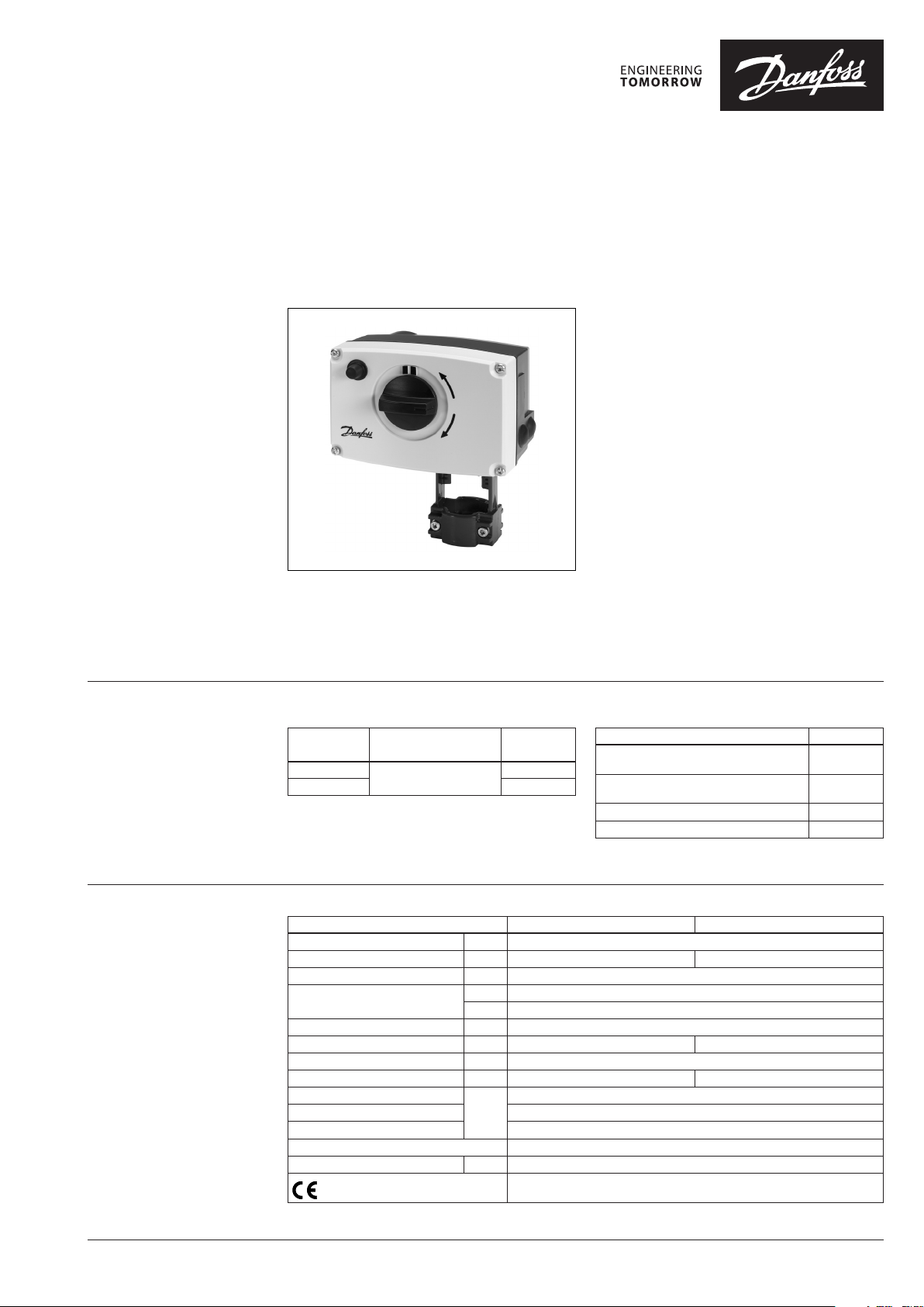
Actuators for modulating control
AME 25, AME 35
Description
AME electric actuators are used with, VRB, VRG,
VF, VL valves
065Z0311, not supplied) and VFS valves up to
DN 50 diameter.
Ordering Actuators
Typ e
AME 25
AME 35 082G3022
with additional adapter (Code No.
Supply voltage
(Vac)
24
Code No.
082G3025
The actuator automatically adapts its
stroke to valve end positions which reduces
commissioning time.
The actuator has some special features:
• The advanced design incorporates load
related ‘switch-off’ to ensure that actuators
and valves are not exposed to overload;
• The advanced design incorporates a
diagnostic LED, operational data capture and
self stroking feature;
• Low weight and robust.
Main data:
• Nominal voltage:
- 24 Vac, 50 Hz/60 Hz
• Control input signal:
- 0(4)…20 mA
- 0(2) … 10 V
• Stroke: 15 mm
• Max. medium temperature: 150 °C
• Self stroking
• Output signal
Accessories
Typ e Code No.
Adapter for VFS 2 valve DN 15-50
(for media temp. over 150 °C)
Adapter for VRB/VRG/VF/VL valves
(gen.2009) DN 15-50
Stem heater for VFS valve DN 15-50 06 5B2171
Clutch AMV(E) 25, AMV(E) 35 003G6396
* Needs to be orde red separately.
065Z 7548
06 5Z03 11*
Technical data
Typ e AME 25 AME 35
Power supply V 24 ac; +10 to –15%
Power consumption VA 4 9
Frequency Hz 50/60
Control input Y
Output signal X V 0 -10 (2-10)
Closing force N 1000 600
Max. stroke mm 15
Speed by 50(60) Hz s/mm 11 ( 8. 8) 3 (2.4)
Max. medium temperature
Ambient temperature 0 … 55
Storage and transpor t temp. –40 … 70
Grade of enclosure IP 54
Weight kg 1.70
- marking in accordance with standards
V 0-10 (2-10) Ri = 24 kΩ
mA 0-20 (4-20) Ri = 500 Ω
150 (200 - with adapter or mounted horizontally)
°C
Low Voltage Directive 73/23/EEC,
EMC-Directive 2006/95/EEC:
- EN 60730-1, EN 60730-2-14
© Danfoss | 2020.11 AI117586476321en-010302 | 1
Page 2
Data sheet Actuators for modulating control AME 25, AME 35
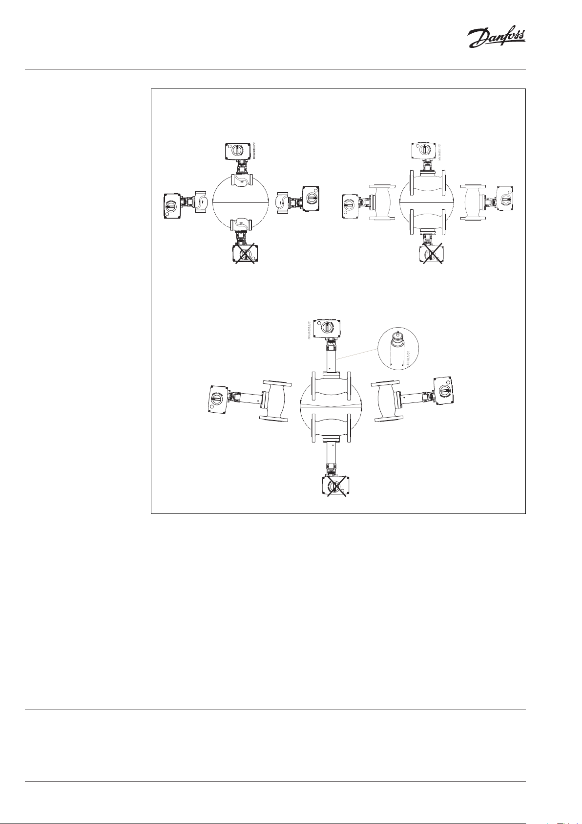
Installation
T
≤150°C for AME 25, 35
max
and VRB, VRG, VF and VL
T
= 200°C for AME 25, 35
max
and VFS
T
≤150°C for AME 25, 35
max
and VFS
Adapter for VFS
(Code No. 065Z7548)
o
≈5
Mechanical
Use 4 mm Allan key (not part of actuator delivery)
to mount actuator on the valve. Installation
of the valve with the actuator is allowed in
horizontal position or upwards. Installation
downwards is not allowed.
The actuator must not be installed in an
explosive atmosphere, at ambient temperature
lower than 0 °C or at ambient temperature higher
than 55 °C. It must not be subject to steam jets,
water jets or dripping liquid as well.
Note: the actuator may be rotated up to 360° with
respect to the valve stem by loosening the retaining
fixture. Once the actuator is placed, retighten
thefixture.
o
≈5
Electrical
Electrical connections can be accessed by
removing the actuator cover. Two cable gland
entries with thread (M20 x 1.5 and M16 x 1.5) are
prepared for cable glands.
Note: Cable and cable gland used must not
compromise the actuator’s IP rating, and must
ensure the connectors are fully strain relieved.
Please observe local rules and regulations as well.
Disposal The actuator must be dismantled and the
elements sorted into various material groups
before disposal.
2 | AI117586476321en-010302 © Danfoss | 2020.11
Page 3

Data sheet Actuators for modulating control AME 25, AME 35
DIP switch setting
vs
I
0 …--- V
Inverse
Sequential
5(6) … 10 V
3 point/RL
Reset
LIN fl ow
Red. K
U
- - -
Direct
2 …--- V
0(2) … 5(6) V
vs
Reset
100 % K
LOG f low
Proportional
The actuator has a function selection DIP switch
under the removable cover. In particular, if SW6
is set to ON, the actuator will perform as 3-point
actuator.
The switch provides the following functions:
•
SW1: U/I - Input signal type selector:
If set to OFF position, voltage input is selected. If
set to ON position, current input is selected.
•
SW2: 0/2 - Input signal range selector:
If set to OFF position, the input signal is in
the range from 2-10 V (voltage input) or from
4-20mA (current input). If set to ON position, the
input signal is in the range from 0-10 V (voltage
input) or from 0-20 mA (current input).
•
SW3: D/I - Direct or inverse acting selector:
If set to OFF position, the actuator is direct acting
(stem lowers as voltage increases). If actuator is
set to ON position the actuator is inverse acting
(stem raises as voltage increases).
•
SW4: —/Seq - Normal or sequential mode
selector:
If set to OFF position, the actuator is working
in range 0(2)-10 V or 0(4)-20 mA. If set to ON
position, the actuator is working in sequential
range; 0(2)-5(6) V or (0(4)-10(12) mA) or
(5(6)-10 V) or (10(12)-20 mA).
•
SW5: 0-5 V/5-10 V - Input signal range in
sequential mode:
If set to OFF position, the actuator is working in
sequential range 0(2)-5(6) V or 0(4)-10(12) mA.
If set to ON position, the actuator is working in
sequential range; 5(6)-10 V or 10(12)-20 mA.
•
SW6: Prop./3-pnt - Modulating or 3-point
mode selector:
If set to OFF position, the actuator is working
normally according to control signal. If set to
ON position, the actuator is working as 3-point
actuator.
For this operation please refer to page 4
(wiring 3-point control).
When DIP switch SW6 is set to ON than all
functions from other DIP switch become inactive.
•
SW7: LOG/LIN - Equal percentage or linear
flow through valve selector 1):
If set to OFF position, the flow through valve
is equal percentage. If set to ON position, the
flow through valve is linear according to control
signal.
•
SW8: 100% KVS/Reduced KVS - Flow reduction
through valve selector 1):
If set to OFF position, the flow through valve
is not reduced. If set to ON position, the flow
through valve is reduced by half of increment
between standard KVS values. Example: valve
with KVS 16 and SW8 set to ON – maximum flow
through the valve is K
standard KVS 16 and next lower standard KVS 10).
1)
NOTE: To be used only in comb ination with valves with equal
percentage characteristic.
•
SW9: Reset:
13 (middle between
VS
Changing this switch position will cause the
actuator to go through a self stroking cycle.
AI117586476321en-010302 | 3© Danfoss | 2020.11
Page 4
Data sheet Actuators for modulating control AME 25, AME 35
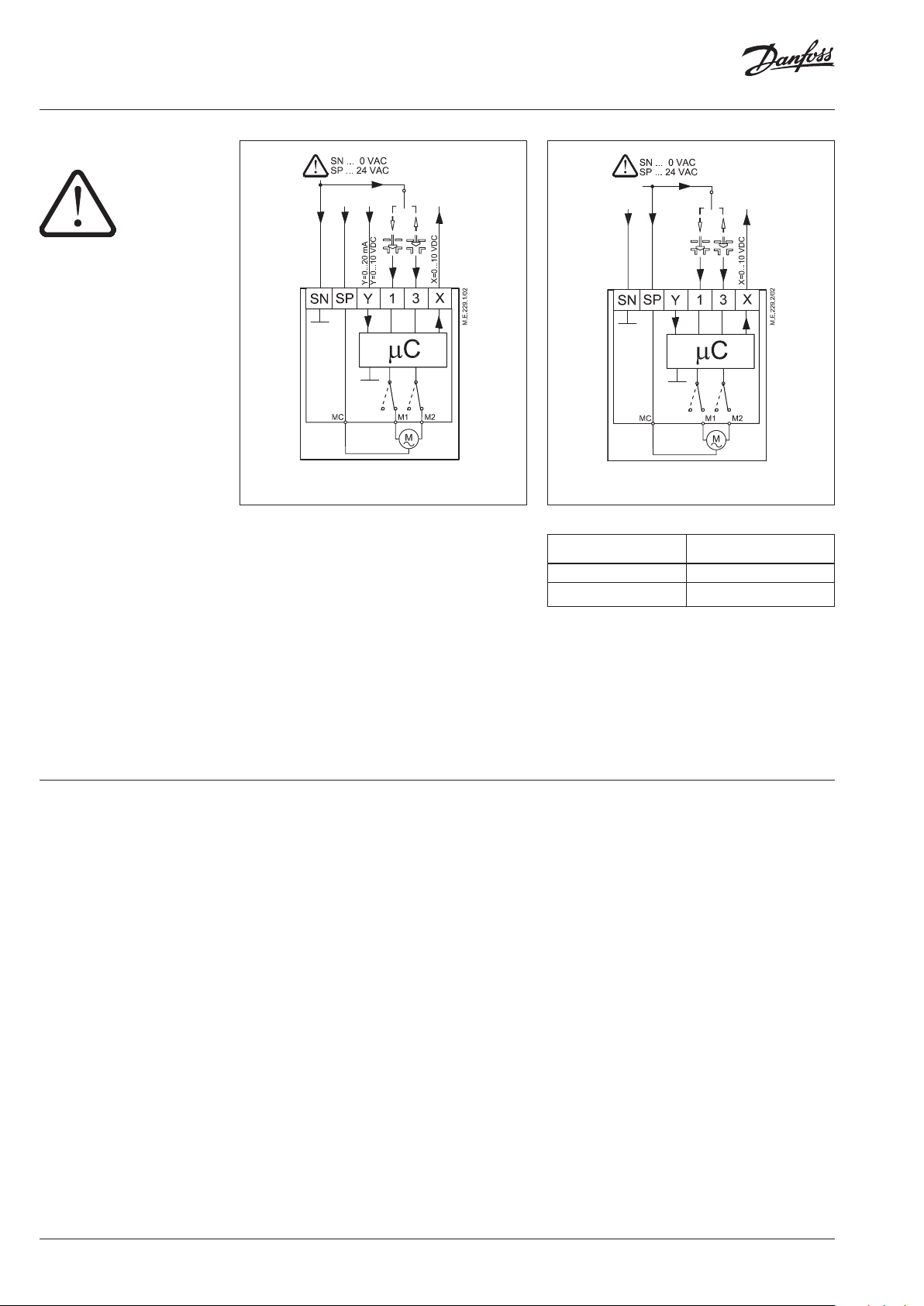
Wiring
24 Vac
Note:
If switch SW6 is set to ON tha n use this wiring.
Wiring for modulating control Wiring for 3-point control
Commissioning
Automatic self stroking feature
When power is first applied, the actuator will
automatically adjust to the length of the valve
stroke. Subsequently, the self stroking feature
can be re-initialised by changing position of SW9.
Diagnostic LED
The red diagnostic LED is located on the pcb
under the cover. It provides indication of three
operational states:
• Actuator Healthy (Permanently ON),
• Self Stroking (Flashes once per second),
• Error (Flashes 3 times per second - seek
technical assistance).
Complete the mechanical and electrical
installation and perform the necessary checks
and tests:
•
Isolate control medium. (E.g. self stroking
in a steam application without suitable
mechanical isolation could cause a hazard).
•
Apply the power.
Note that the actuator will now perform the
self stroking function.
•
Apply the appropriate control signal and
check the valve stem direction is correct for
the application.
•
Ensure that the actuator drives the valve over
its full stroke, by applying the appropriate
control signal. This action will set the valve
stroke length.
Wiring length
0-50 m 0.75 mm
> 50 m 1.5 mm
Recommended
square of the wiring
2
2
SP 24 V ac .........................................Power supply
SN 0 V ........................................................ Common
Y 0-10 V .............................................. Input signal
(2-10 V)
0-20 mA
(4-20 mA)
X 0-10 V ...........................................Output signal
(2-10 V)
Commissioning / testing feature
The actuator can be driven to the fully open or
closed positions (depending on valve type) by
connecting SN to terminals 1 or 3.
The unit is now fully commissioned.
4 | AI117586476321en-010302 © Danfoss | 2020.11
Page 5

Data sheet Actuators for modulating control AME 25, AME 35
Manual override The manual override is achieved by turning the
manual knob to the required position.
Observe the direction of rotation symbol.
If manual override has been used then X and Y
signal are not correct until the actuator reaches
its end position. If this is not accepted, mount
accessory active return signal kit.
Procedure
• Press rubber button
• Adjust valve position using control knob
• Set valve to closed position
• Restore power supply
Actuator - valve
combinations
AME 25, AME 35 +
Adapter (065Z0311)
VRB 2, VRB 3 ext. thread (DN 15-50)
VRG 2, VRG 3 ext. thread (DN 15-50)
AME 25, AME 35 +
Adapter (065Z0311)
VRB 2, VRB3 Int. thread
(DN 15-50)
AME 25, AME 35 +
VFS 2 (DN 15-50)
AME 25, AME 35 +
Adapter (065Z0311)
VF 2, VF 3 (DN 15-50)
VL 2, VL 3 (DN 15-50)
AI117586476321en-010302 | 5© Danfoss | 2020.11
Page 6

Data sheet Actuators for modulating control AME 25, AME 35
Dimensions
Adapter 065Z0311
for VRG, VRB, VF, VL (DN 15-50)
Adapter 065Z7548
for VFS (DN 15-50)
for media temperatures over 150 oC
6 | AI117586476321en-010302 © Danfoss | 2020.11
Page 7

Data sheet Actuators for modulating control AME 25, AME 35
AI117586476321en-010302 | 7© Danfoss | 2020.11
Page 8

Data sheet Actuators for modulating control AME 25, AME 35
© Danfoss | DHS-SRMT/SI | 2020.118 | AI117586476321en-010302
 Loading...