

Operating Guide
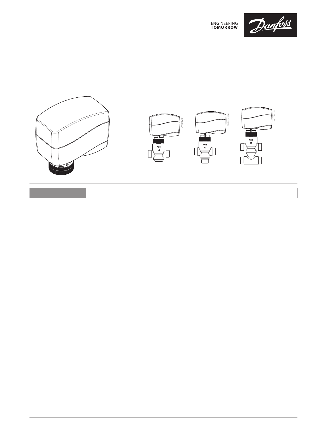
AME 140X
ENGLISH
AME 140X +
VZ 2, VZL 2
Actuators for modulating control AME 140X www.danfoss.com Page 5
AME 140X +
VZ 3, VZL 3
AME 140X +
VZ 4, VZL 4
© Danfoss | 2017.01
VI.IR.A2.02 | 1
AME 140X
❶
❷
MAINTENANCE
FREE
5-95 % RH
no condensing
①
②
③
❸
❹
④
②
③
①
0-10 V (2-10); Ri=200 kΩ
Y
0-20 MA (4-20; Ri=500 Ω
X 0-10 V (2-10); Ro
0-10 V
INV
SEQ
5-10 V
MOD
ASTX
I
---
DIR
2-10 V
U
---
LIN
0-5 V
(min)
=38 kΩ
2 | © Danfoss | 2017.01
VI.IR.A2.02
AME 140X
❹
❺
③
L R
②
②
①
④
①
①
R
+
⑤
②
L
L
VI.IR.A2.02
⑥
R
© Danfoss | 2017.01 | 3

AME 140X
mm
LED Indication type Operating mode
❻
Constantly lit
Positioning mode - Actuator is retracting the stem
Constantly lit
Positioning mode - Actuator is extracting the stem
Green
Flashing (1 s cycle)
Self stroking mode - Actuator is retracting the stem
Self stroking mode - Actuator is extracting the stem
Flashing (1 s cycle)
Constantly lit
Stationary mode - Actuator has reached upper end position (retracted stem)
Yellow
Stationary mode - Actuator has reached bottom end position (extracted stem)
Constantly lit
Flashing (2.5 s cycle) Stationary mode
Red Flashing (1 s cycle) Error Mode
Dark No indication No power supply
❼
92
50
92
H
h
L
AME140X +
VZ (DN 15, 20)
Valve t ype d
VZ 2 / DN 15 G ½” 65
VZ 2 / DN 20 G ¾” 77
VZ 3 / DN 15 G ½” 65
VZ 3 / DN 20 G ¾” 77
VZ 4 / DN 15 G ½” 65
VZ 4 / DN 20 G ¾” 77
88
d
L H H1h
mm
26.5
119 125
68
92
H
4.7
Ø5
Stem extension
plug
Valve t ype d
VZL 2 DN 15 G ½” 65 111 117 29.5
VZL 2 DN 20* G ¾” 77 117 123 34.0
35
65
VZL 3 DN 15 G ½” 65 111 117 35.0
VZL 3 DN 20 G ¾” 77 117 12 3 35.0
VZL 4 DN 15 G ½” 65 111 117 51. 0
VZL 4 DN 20* G ¾” 77 117 123 65.0
* conex valve s DN 20 - G 1 ¹/₈” 14 TPI
1
h
L
AME 140X + VZL (DN15, 20)
+ stem extension plug
L H H1h
d
1
4 | © Danfoss | 2017.01
VI.IR.A2.02

AME 140X
ENGLISH
Safety Notes
To avoid injury of persons and
damages to the device, it is absolutely
necessary to read and observe these
instructions carefully.
Necessary assembly, start-up, and maintenance
work must be performed by qualified and
authorized personnel only.
Please comply with the instructions of the
system manufacturer or system operator.
Do not remove the cover befo re the
power supply is fu lly switched off.
AC 24 V
Connect via safet y isolating
transformer.
Disposal instruction
This product should be dismantled
and its components sorted, if possible,
in various groups befo re recycling or
disposal.
Always follow the local disposal regulations.
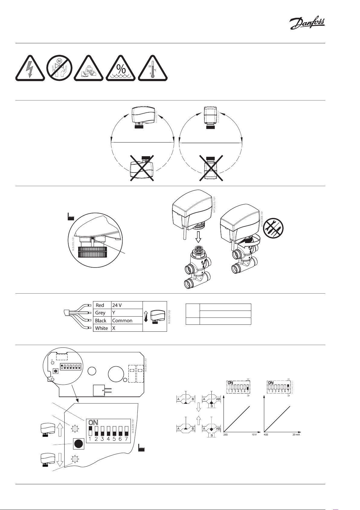
Mounting ❶
The actuator should be mounted with the valve
stem in either horizontal position or pointing
upwards.
Installation ❷
• Check the valve neck.
• The actuator should be in steam up position
(factory setting) ①.
• Ensure that the actuator is mounted securely
on the valve body ②, ③.
The actuator is fixed to the valve body by
means of a ribbed nut which requires no
tools for mounting. The ribbed nut should
be tightened by hand.
• Wire the actuator according to the wiring
diagram ❸.
• The direction of stem movement can be
observed on the position indicator ①.
Auto sleep mode
1. If actuator is not mounted to the valve but
connected to the power supply, it will first
run to its extracted end position (buzz noise
from the motor will appear). This behavior
will last for max 3 minutes when power
supply will be automatically cut off from
electro motor and LED indicators.
2. It is mandatory to drive the spindle of the
actuator to upper position before it will be
installed on valve (please refer to manual
override drawings)!
3. Auto sleep mode switches back to learning
mode by pressing RESET button or by
cycling power supply.
Wiring ❸
Do not touch anythi ng on the PCB!
Switch off the power li ne before wire
the actuator! Lethal vo ltage!
Wire the actuator accordin g to the wiring
diagram.
DIP switch settings ❹
Factory settings:
ALL switches (except SW 1 which is in ON
position) are in OFF position! ④
NOTE:
All combinations of DIP switches are allowed.
All functions that are selected are added
consecutively.
SW 1: 0/2 - Input signal range selector
If set to OFF position, the input signal is in
the range from 2-10 V (voltage input) or from
4-20mA (current input).
If set to ON position, the input signal is in the
range from 0-10 V (voltage input) or from 0-20
mA (current input).
SW 2 : D/I - Direct or inverse acting selector
If set to OFF position, the actuator is direct
acting (stem lowers as voltage increases).
If the actuator is set to ON position, the
actuator is inverse acting (stem raises as voltage
increases).
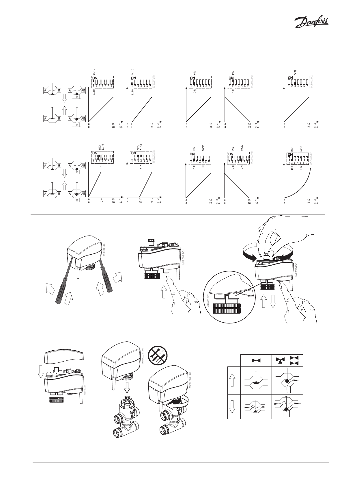
SW 3: ---/Seq - Normal or sequential mode
selector
If set to OFF position, the actuator is working in
range 0(2)-10 V or 0(4)-20 mA.
If set to ON position, the actuator is working in
sequential range; 0(2)-5(6) V or (0(4)-10(12)mA)
or (5(6)-10 V) or (10(12)-20 mA).
SW 4: 0-5 V/5-10 V - Input signal range in
sequential mode
If set to OFF position, the actuator is working in
sequential range 0(2)-5(6) V or 0(4)-10(12) mA.
If set to ON position, the actuator is working in
sequential range; 5(6)-10 V or 10(12)-20 mA.
SW 5: LIN/MOD - Linear or modified flow
through the VZL valves
If set to ON position, the flow through the
LINEAR characterized VZL valve will modify to
equal percentage-wise equals the control signal.
If set to OFF position, the flow through the valve
VZ or VZL remains same as is valve characteristic
in accordance to the control signal.
SW 6: ---/ASTK - Anti-blocking function
Exercises the valve to avoid blocking in periods
when the heating/cooling is off.
If set to ON position (ASTK), the valve motion is
switched on. The actuator opens and closes the
valve every 7 days.
If set to OFF position (---), the function is
disabled.
SW 7: U/I - Input signal type selector
If set to OFF position, voltage input is selected.
If set to ON position, current input is selected
Reset button ❹③
Press the reset button will cause the actuator to
go through a self stroking cycle (press it for 2 s).
Manual override ❺
Do not man ually oper ate the drive
if power is c onnected !
Do not dis mount the ac tuator
from the val ve when it is in a ste m down
position!
If dismounted in a stem down p osition, there is a
high risk that the actuator g ets stuck.
- Remove cover ①
- Press and hold the button (on the bottom
side of the actuator) ② during manual
override ③
- Replace cover ④
- Install actuator on valve ⑤, ⑥
Remark:
A ‘click’ sound af ter energising the actuator
indicates that the gear wheel has jumped into
normal position.
LED signalisation ❻
- lit - no - flashing
0-10 V
INV
SEQ
5-10 V
MOD
ASTX
I
U
---
---
LIN
DIR
0-5 V
2-10 V
Dimensions ❼
Part Name
部件名称
Connecting nut/
连接螺母
O: Indica tes that this hazar dous substance co ntained in all of the h omogeneous ma terial for this par t is below the limi t requirement in GB /T 26572;
O: 表示该有害物质在该部件所有均质材料中的含量均在GB/T 26572规定的限量要求以下。
X: Indica tes that this hazar dous substance co ntained in at leas t one of the homoge neous material fo r this part is above t he limit requirem entw in GB/T 26572;
X: 表示该有害物质至少在该部件的某一均质材料中的含量超出GB/T 26572规 定的限量要求。
Lead (P b)
铅 (Pb)
X O O O O O
Mercur y (Hg)
汞 (Hg)
Cadmium (Cd)
镉 (Cd)
Hazardous Substances Table/有害物质含量表
Hexavalent Chromium (Cr(V I))
六价铬 (Cr (VI))
Polybrominated biphenyls (PBB)
多溴联 苯 (PB B)
VI.IR.A2.02
Polybrominated diphenyl ethers (PBDE)
多溴二 苯醚 (PBDE)
© Danfoss | 2017.01 | 5

AME 140X
6 | © Danfoss | 2017.01
VI.IR.A2.02

AME 140X
VI.IR.A2.02
© Danfoss | 2017.01 | 7

Danf
already on order pro
All trademarks in this material are property of the respec
AME 140X
oss can accept no responsibility for possible errors in catalogues, brochures and other printed material. Danfoss reserves the right to alter its products without notice. This also applies to products
vided that such alterations can be made without subsequential changes being necessary eady agreed.
8 | © Danfoss | DHS-SRMT/SI | 2017.01
tive companies. Danfoss and the Danfoss logotype are trademarks of Danfoss A/S. All rights reserved.
73691500 / VI.IR.A2.02
 Loading...