

Operating Guide
Ste m Trav el
5,5 mm
COM
COM
AME 13 SU/SD-1
➊
Travel Speed 11,7 (14) s/mm
MAINTENANCE
FREE
5-95 % RH
no condensing
AME 13 SD-1 +
AB-QM
Washer 003Z0257 Adapter 003Z3960
AME 13 SU-1 +
AB-QM
AUTO
=
=
4 – 6 mm × 1 mm
❷
Do not use as
ON/Off actuator.
AME13 SU/SD-1, Modulang
SN SP Y 1 3 X
~ AC 24V
50/60Hz
0(2)-10VDC
0(4)-20mA
+
DC 0-10V
AME13 SU/SD-1, Floang point
SN SP Y 1 3 X
+
~ AC 24V
50/60Hz
DC 0(2)-10V
+
AQ283757724898en-000301 | 1© Danfoss | 2020.03
AME 13 SU/SD-1
Loss of Power
❸
SD
½”
④
①
②
⑤
Max. 6 Nm/53 in-lb
for AB-QM valves.
③
Loss of Power
SU
½”
④
①
②
Max. 6 Nm/53 in-lb
for AB-QM valves.
⑤
③
AQ283757724898en-000301 2 | © Danfoss | 2020.03

AME 13 SU/SD-1
❹
121 ( 4.76”)
83 (3.27”)
110 (4. 33 ”)
min. 200 (7.87”)
❺
① ② ③
④
⑦
⑤ ⑥
⑧
⑨
© Danfoss | 2020.03 | 3AQ283757724898en-000301

AME 13 SU/SD-1
ENGLISH
Safety Note
To avoid personal injury and damage to
the device or other property, it is
necessary to read and follow these
instructions carefully.
Assembly, start-up, and maintenance work
must be performed by qualified and authorized
personnel.
Comply with the instructions of the system
manufacturer or system operator.
Please comply with the instructions of the
system manufacturer or system operator.
Do not remove the cover before th e
power supply is ful ly switched off.
Disposal
This product shou ld be dismantled
and its components sorted, if
possible, in various grou ps before
Always follow the local d isposal regulations.
recycling or disposal .
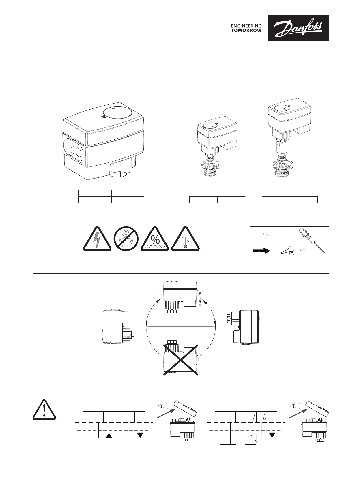
Mounting Position ➊
The actuator should be mounted with the valve
stem in either a horizontal position or pointing
upwards.
Wiring ❷
AC 24 V
Connect via Class 2 (Nor th America)
or Safety E xtra-Low Voltage (SELV)
(Europe). Failure to comply can lead to
equipment damage or personal injury.
Switch off power bef ore wiring the
actuator!
1. Make all wiring connections in accordance
with local, national, or regional regulations.
2. For applications requiring conduit, a field
supplied 1/2” trade size electrician’s fitting
and lock nut can be mounted in the actuator
enclosure. Use flexible metallic tubing or its
equivalent with the field supplied fitting.
3. Insert wiring material through the removable
plug or conduit fitting, and connect to the
terminal block using the applicable wiring
diagram ❷.
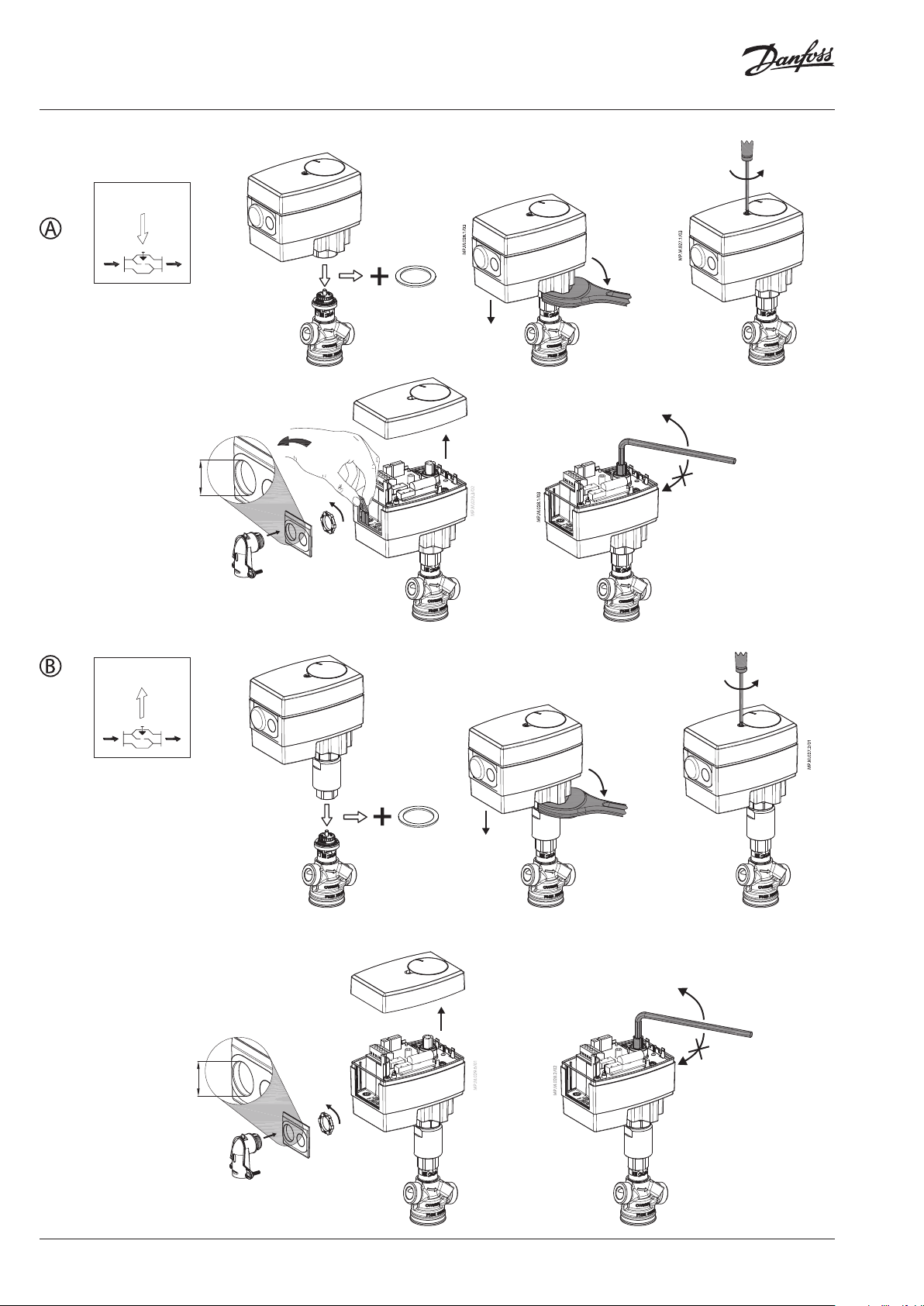
Installation ❸
1. Depending on the version of actuator
(SU/SD) prior to installation an included washer
and adapter is required to be installed:
SD, Washer (003Z0257)
The washer is placed on the valve neck prior to
the installation of the actuator.
SU, Adapter (003Z3960) and washer (003Z0257)
Hand tighten the adapter to the neck of the
valve. The actuator will be installed to the
adapter.
2. The actuator should be in the full up position
① (factory setting). If it is not, refer to the
manual override instructions ❸④.
3. The actuator is fixed to the valve body or
adapter by means of a union nut which requires
an adjustable wrench to assist in tightening the
actuator to the valve.
DIP switch settings ❺
Factory settings:
ALL switches are on OFF position!
(except SW2 which is in ON position)!
NOTE:
All combinations of DIP switches are allowed.
All functions that are selected are added
consecutively. There is only one logic override of
functionalities i.e. the switch No.6 Propor tional /3
point, which sets actuator to ignore control signal
and works as a “simple” 3-point actuator.
SW 1: VDC / mA - Input signal type
selector ①
If set to OFF position, voltage input is
selected. If set to ON position, current input is
selected.
SW 2: 0/2 - Input signal range selector ②
If set to OFF position, the input signal is in the
range from 2-10 V (voltage input) or from 4-20
mA (current input). If set to ON position, the
input signal is in the range from 0-10 V (voltage
input) or from 0-20 mA (current input).
SW3: D/I - Direct or inverse acting
selector ③
If set to OFF position, the actuator is direct
acting (stem retracts as voltage increases). If
the actuator is set to ON position, the actuator
is inverse acting (stem extends as voltage
increases).
SW4:---/Seq - Normal or sequential
mode selector ④
If set to OFF position, the actuator is working
normally in 0(2)-10V or 0(4)-20mA range. If set
to ON position, the actuator is working in a
sequential mode with its range dependent on
the position of SW 4.
SW5: 0-5 V/5-10 V - Input signal range in
sequential mode ⑤
If set to OFF position, the actuator is working in
sequential range 0(2)-5 (6) V or 0(4)-10 (12) mA.
If set to ON position, the actuator is working in
sequential range; 5(6)-10 V or 10(12)-20 mA
SW6: Proportional/Floating point ⑥
If set to ON position, the actuator can operate
as Floating point actuator. Power supply should
be connected on SN and SP ports. On port 1 or 3
24 VAC signal is connected for rising or lowering
of actuator. Return signal X indicates the correct
position.
If set to OFF position, the actuator operates on
modulating input signal.
NOTE:
if 3 point function is selected actuator does not
respond to any control signal on port Y. It only rises
and lowers spindle if power is supplied on port 1
or 3.
SW7: LIN/LOG - Linear or equal
percentage flow through valve selector
⑦
If set to ON position, the flow through the valve
is equal percentage to the control signal.
If set to OFF position, the valve position is linear
acc. to the control signal.
SW8: ⑧
Set to ON for valve bodies 1/2” to 1-1/4” HF. The
actuator will modulate on max stem travel of
4.5mm.
Set to OFF for valve body 1/2” Low flow. The
actuator will modulate on max stem travel of
2.5mm.
SW9: Reset ⑨
Toggling the switch will cause the actuator to go
through an auto-calibration cycle.
Function test
The indicator light shows whether the
positioner is in operation or not. Moreover, the
indicator shows the control status and faults.
Constant light
- normal operation
No light
- no operation or no power supply
Intermittent light (1 Hz)
- self adjusting-mode
Intermittent light (3 Hz):
- power supply too low
- insufficient valve stroke (<20 s)
- end-position cannot be reached.
73694760 / AQ283757724898en-0003014 | © Danfoss | DHS-SMDBT/SI | 2020.03
 Loading...