

Operating Guide
AME 130(H), AME 140(H)
AME 130, 140
AME 130H, 140H
ENGLISH
DANSK
DEUTSCH
NEDERLANDS
LIETUVIŲ K.
LATVISKI
MAGYAR
ČESKY
POLSKI
AME + VZ 2 / VZL 2 AME + VZ 3 / VZL 3 AME + VZ 4 / VZL 4
Actuators for modulating control
AME 130, AME 140, AME 130H, AME 140H
Motorer til modulerende styring AME 130, AME 140, AME 130H, AME 140H www.danfoss.dk Side 6
Stellantriebe für stetiges Eingangssignal
AME 130, AME 140, AME 130H, AME 140H
Servomotoren voor modulerende regeling
AME 130, AME 140, AME 130H, AME 140H
Tolygaus valdymo pavaros AME 130, AME 140, AME 130H, AME 140H www.danfoss.lt 9 puslapis
Modulēšanas vadības izpildmehānismi
AME 130, AME 140, AME 130H, AME 140H
AME 130, AME 140, AME 130H, AME 140H szelepmozgató motorok
arányos szabályozáshoz
Servopohony s modulačním regulačním signálem
AME 130, AME 140, AME 130H, AME 140H
Siłowniki do sterowania modulacyjnego
AME 130, AME 140, AME 130H, AME 140H
www.danfoss.com Page 5
www.danfoss.de Seite 7
www.danfoss.nl Pagina 8
www.danfoss.com Lpp. 10
www.danfoss.com 11. oldal
www.danfoss.cz Strana 12
www.danfoss.pl Strona 13
AME + AHQM
© Danfoss | 2017.07
VI.KU.M6.9O | 1
AME 130(H), AME 140(H)
❶
❷
MAINTENANCE
FREE
5-95 % RH
no condensing
30°
30°
4 – 6 mm × 1 mm 6 mm
❸
①
Red
Gray
Black
24 VAC
Y 0 - 10 VDC
Common
2 | © Danfoss | 2017.07
VI.KU.M6.9O
AME 130(H), AME 140(H)
Reset
0V…---V
Inverse
Sequential
5(6)…10 V
I
➍
Reset
①
U I
--- S equential
Reset
Direct Inverse
2 V...---V 0V...---V
0(2)...5(6)V 5(6)...10V
② ③
④ ⑤
➎
⑥
AME 130, 140
①
②
⑦
6 mm
⑤
④
VI.KU.M6.9O
③
© Danfoss | 2017.07 | 3
AME 130(H), AME 140(H)
mm
mm
AME 130H, 140H
❻
stem up
2 port
3 or 4 port
➐
92
H
h
L
AME 130/140 +
VZ (DN 15, 20)
Valve t ype d
VZ 2 / DN 15 G ½” 65
VZ 2 / DN 20 G ¾” 77
VZ 3 / DN 15 G ½” 65
VZ 3 / DN 20 G ¾” 77
VZ 4 / DN 15 G ½” 65
VZ 4 / DN 20 G ¾” 77
88
H
d
L H H1h
①
92
68
AME 130, 140
92
1
L
AME 130H/140H +
VZ 2, VZ 3, VZ 4 (DN 15, 20)
26.5
119 125
35
65
①
stem down
50
94
d
4.7
Ø5
Stem extension
plug
h
92 50
74
AME 130H, 140H
92
H
1
L
AME130/140 + VZL
+ stem exte nsion plug
Valve t ype d
VZL 2 DN 15 G ½” 65 111 117 29.5
VZL 2 DN 20* G ¾” 77 117 123 34.0
VZL 3 DN 15 G ½” 65 111 117 35.0
VZL 3 DN 20 G ¾” 77 117 12 3 35.0
VZL 4 DN 15 G ½” 65 111 117 51.0
VZL 4 DN 20* G ¾” 77 117 123 65.0
* conex valve s DN 20 - G 1 ¹/₈” 14 TPI
1
H
d
L H H1h
92
L
AME130H/140H + VZL
+ stem exte nsion plug
1
1
2
H
H
L
4 | © Danfoss | 2017.07
DN 15 20 25 32
L
1
L
2
H
1
H
1
L
2
2
118 125 141 160
148 156 174 194
mm
168 178 19 6 216
152 162 180 200
VI.KU.M6.9O
AME 130(H), AME 140(H)
Gray
Y 0-10 VDC
Black
Common
Reset
0V…---V
Inverse
Sequential
5(6)…10 V
I
ENGLISH
Safety Note
To avoid injury of persons and
damages to the device, it is absolutely
necessary to read and observe these
instructions carefully.
Necessary assembly, start-up, and maintenance
work must be performed by qualified and
authorized personnel only.
Please comply with the instructions of the
system manufacturer or system operator.
Do not remove the cover before th e
power supply is ful ly switched off.
Disposal instruction
This product shou ld be dismantled
and its components so rted, if possible,
in various groups befo re recycling or
disposal.
Always follow the local d isposal regulations.
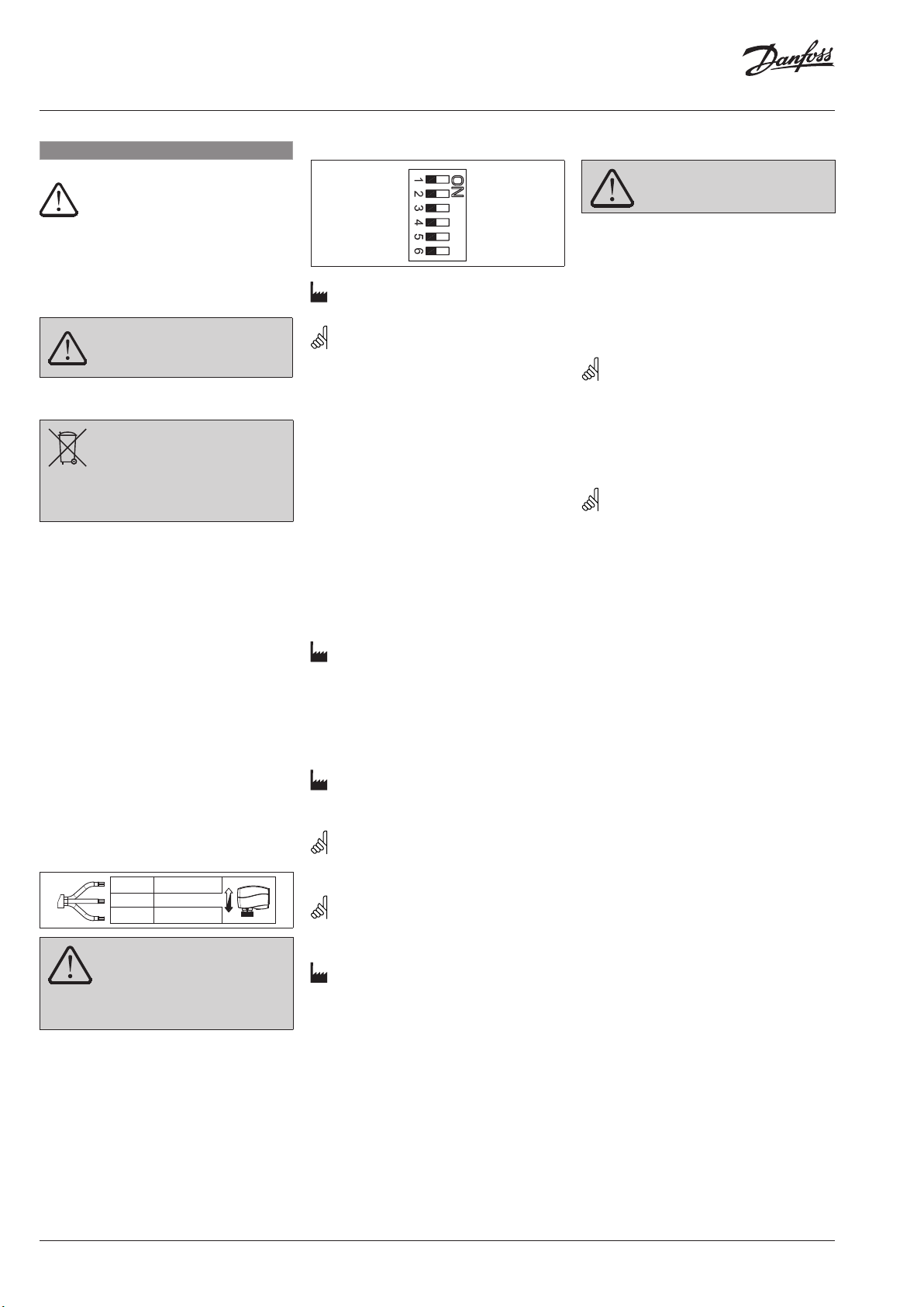
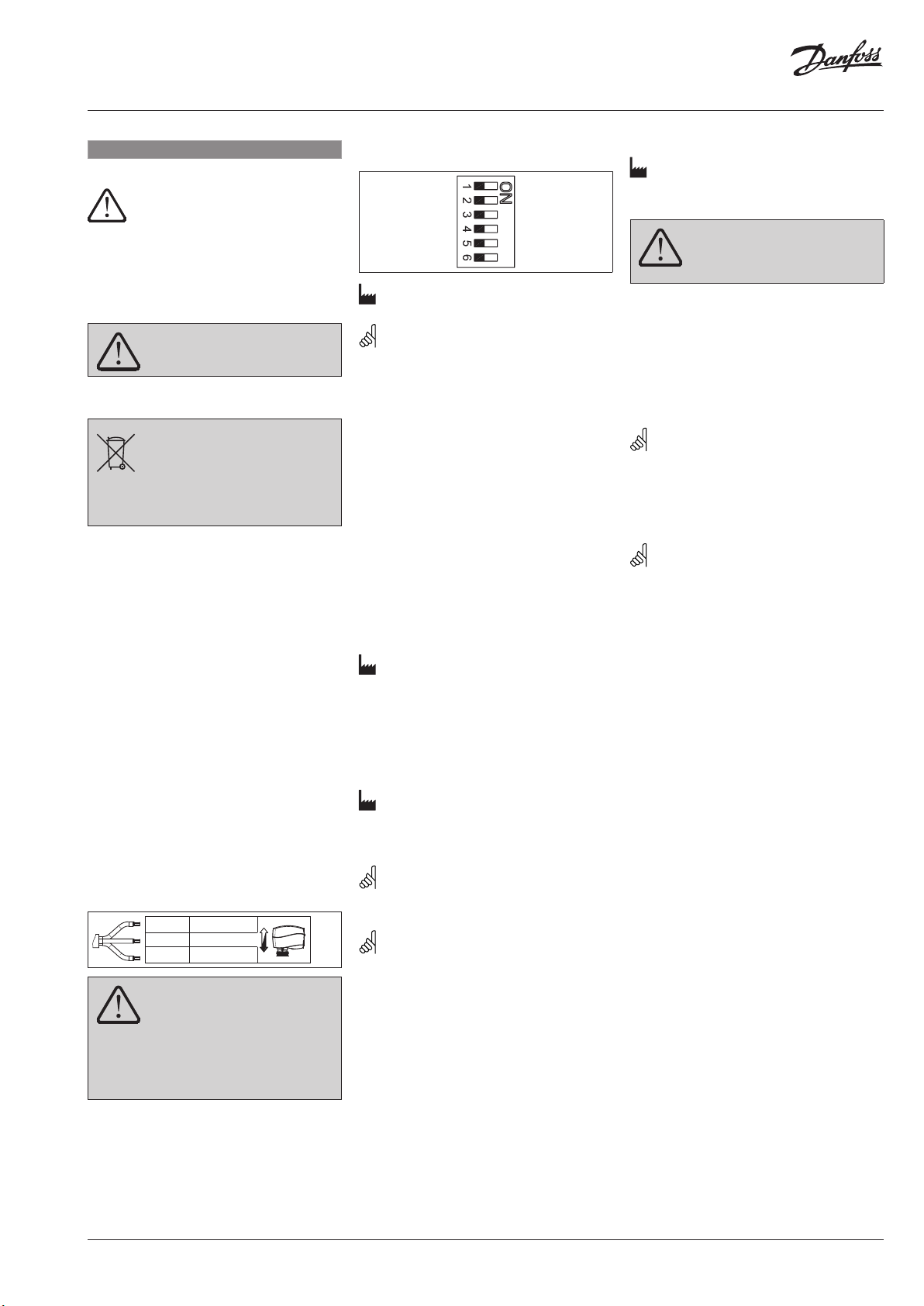
Mounting ➊
In case of ship applications (on water) actuator
should be mounted with the valve stem in
either 30° above horizontal position or pointing
upwards.
In case of building applications actuator should
be mounted with the valve stem in either
horizontal position or pointing
upwards.The actuator is fixed to the valve body
by means of a ribbed nut which requires no
tools for mounting. The ribbed nut should be
tightened by hand.
Installation ❷
1. Check the valve neck. The actuator should
be in steam up position (factory setting).
Ensure that the actuator is mounted securely
on the valve body
2. Wire the actuator according to the wiring
diagram
3 The direction of stem movement can be
observed on the position indicator ①
Wiring ❸
Red 24 VAC
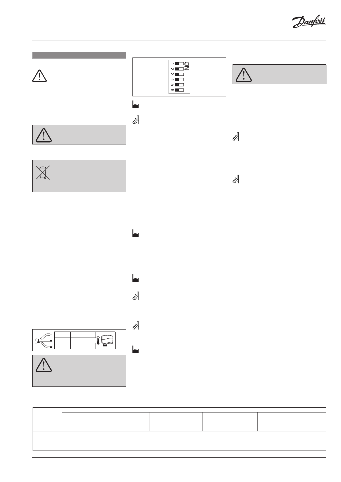
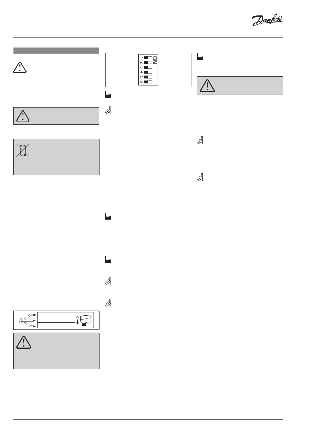
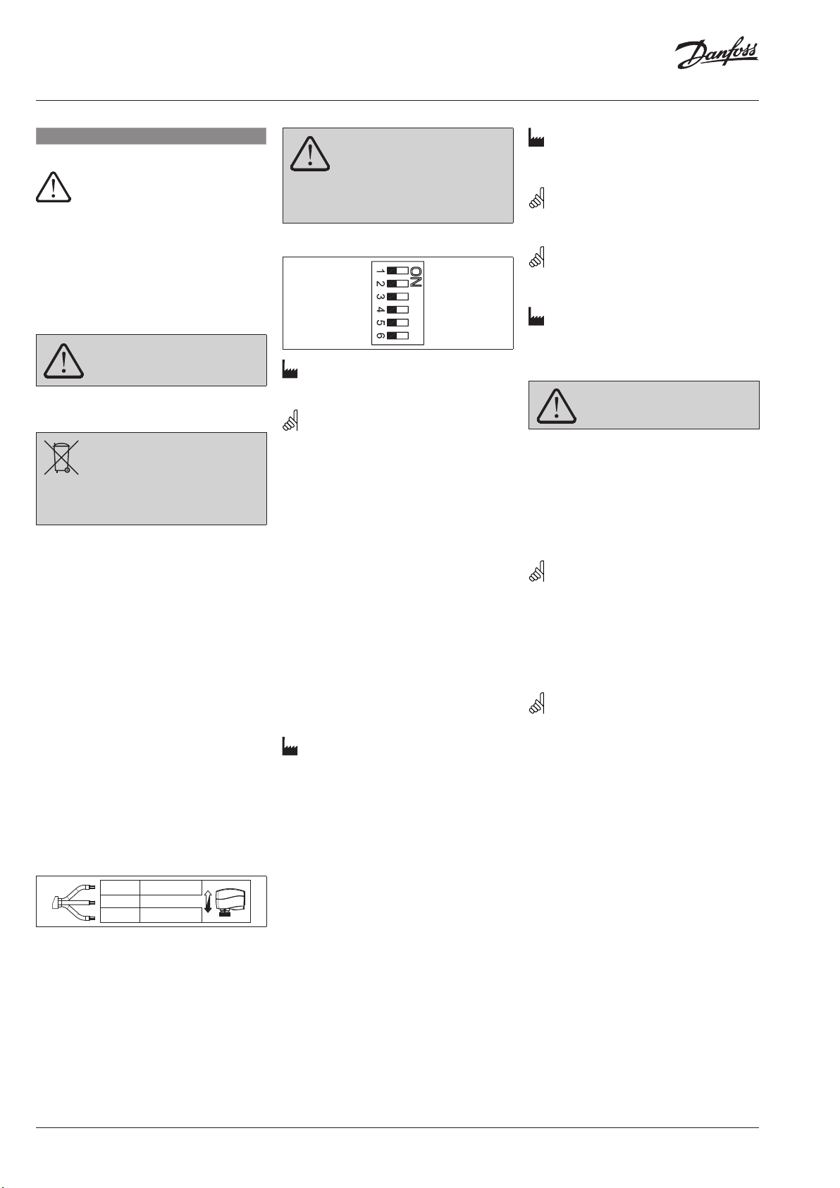
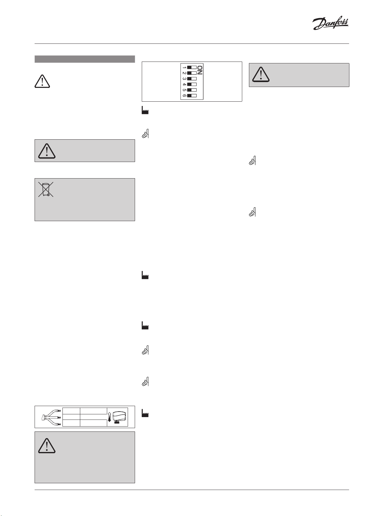
DIP switch settings ➍
Reset
2 V...---V 0V...---V
Direct Inverse
--- S equential
0(2)...5(6)V 5(6)...10V
U I
Factory settings:
ALL switches are on OFF position!
NOTE: All combinations of DIP switches are
allowed. All functions that are selected are
added consecutively.
SW1: Reset ②
After the actuator has been connected to
power supply, the actuator will start the selfadjustment procedure. The indicator LED ①
flashes until self adjustment is finished. The
duration depends on the spindle travel and will
normally last a few minutes. The stroke length
of the valve is stored in the memory after self
adjustment has been completed. To restart self
adjustment, change the position of the RESET
switch (switch No.1). If the supply voltage is
switched off or falls below 80 % in more than
0.1 s, the current valve position will be stored
in the memory and all data remain saved in the
memory also after a power supply cut-out.
SW2: 2-10 V/0-10 V ③
Factory setting is:
2-10 V.
SW3: Direct/Inverse ④
The actuator can be set for the spindle to
travel downwards on the rising control signal
(DIRECT), OR for the spindle to travel upwards
on the rising control signal (INVERSE)
Factory setting is:VI.KU.M6.9ODIRECT
SW4: ---/Sequential ⑤
NOTE: This combination works in
combination with switch No.5: 0(2)-5(6) V/5(6)10 V.
SW5: 0(2)-5(6) V/5(6)-10 V ⑥
NOTE: This function is available if switch
No.4: ---/Sequential is set.
SW6: U/I ⑦
Reset
Manual override
(for service purposes only)
Do not manually operate the drive
under power!
AME 130, AME 140 ➎
① Remove the cover
② Insert the Allen key 6 into the spindle
③ Press and hold the button (on the bottom
side of the actuator) during manual override
④ Pull out the tool
⑤ Replace cover
Remark: A ‘click’ sound af ter energising
the actuator means that the gear wheel has
jumped into normal position.
AME 130H, AME 140H ❻
Press and hold the button ① (on the bottom
side of the actuator) during manual override.
Remark: A ‘click’ sound af ter energising
the actuator means that the gear wheel has
jumped into normal position.
Function test
The light emitting diode (LED) ❹① indicates
whether the actuator is in operation or not, the
operating status, and failures, if any.
• No light
- no operation or no power supply
• Constant light
- normal operation
• Flashing light (1 Hz)
- self-adjusting mode
• Flashing light (~ 3 Hz):
- power supply too low
- initial self-adjusting time to short due too
short valve’s stroke must last more than 12
sec.
Dimensions ❼
Factory setting:
Do not touch anythin g on the PCB!
voltage control signal (2-10 V).
Switch off the power lin e before
wiring the actuator! Lethal voltage!
Wire the actuator according to the
wiring diagram.
Part Name
部件名称
Connecting nut
连接螺母
O: Indica tes that this hazar dous substance con tained in all of the h omogeneous ma terial for this par t is below the limi t requirement in GB /T 26572;
O: 表示该有害物质在该部件所有均质材料中的含量均在GB/T 26572规定的限量要求以下。
X: Indica tes that this hazar dous substance co ntained in at least o ne of the homogen eous material fo r this part is above th e limit requirem entw in GB/T 26572;
X: 表示该有害物质至少在该部件的某一均质材料中的含量超出GB/T 26572规 定的限量要求。
VI.KU.M6.9O
Lead (P b)
铅 (Pb)
X O O O O O
Mercur y (Hg)
汞 (Hg)
Cadmium (Cd)
镉 (Cd)
Hazardous Substances Table/有害物质含量表
Hexavalent Chromium (Cr(V I))
六价铬 (Cr (VI))
Polybrominated biphenyls (PBB)
多溴联 苯 (PB B)
Polybrominated diphenyl ethers (PBDE)
多溴二 苯醚 (PBDE)
© Danfoss | 2017.07 | 5
AME 130(H), AME 140(H)
Rød
24 VAC
Grå
Y 0-10 VDC
Reset
0V…---V
Inverse
Sequential
5(6)…10 V
I
DANSK
Sikkerhedsbestemmelser
For at undgå skader på personer og
udstyr, er det absolut nødvendigt at
gennemlæse følgende vejledning.
Montering, opstart og vedligeholdelse må kun
foretages af kvalificeret og autoriseret
personale.
Følg fabrikantens eller operatørens
instruktioner.
Dækslet må ikke ernes, før
strømforsyningen er ernet fra
stikkontakten.
Bortskaffelse
Før genbrug eller b ortskaffelse skal
dette produk t skilles ad, og
komponenterne skal sor teres i
forskellige materialegrupper.
Der henvises til de lokal e regulativer for
bortskaffelse.
Montering ➊
I tilfælde af anvendelser ombord på et skib skal
motoren monteres med ventilspindelen i enten
30° over vandret stilling eller pegende opad.
I tilfælde af anvendelser i bygninger skal
motoren monteres med ventilspindelen i enten
vandret eller pegende opad.
Motoren monteres på ventilhuset med en riflet
møtrik, der kan monteres uden værktøj. Den
riflede møtrik skal spændes med håndkraft.
Installation ❷
1. Kontroller ventilens hals. Motoren skal stå
i en position med spindelen trukket op.
(fabriksindstilling). Kontroller, at motoren er
monteret solidt på ventilhuset.
2. Tilslut motoren iht. ledningsdiagrammet – se
ovenfor.
3. Spindelens bevægelsesretning kan ses på
positionsindikatoren ①.
Wiring ❸
El-tilslutning ❹
Nulstilling
2 V...---V 0V...---V
Direkte Omvendt
--- Sek ventiel
0(2)...5(6)V 5(6)...10V
U I
Fabriksindstillinger:
ALLE omskiftere er stillet på OFF!
BEMÆRK: Alle kombinationer af
funktionsomskifterindstillinger er tilladt.
Alle funktioner, der vælges, tilføjes i den
rækkefølge, hvori de vælges.
SW1: Nulstilling ②
Når motoren er tilsluttet netspænding, starter
den en selvjusteringsprocedure. LED-dioden ①
blinker, indtil selvjusteringen er gennemført.
Varigheden afhænger af spindelens vandring
men tager normalt nogle få minutter. Ventilens
slaglængde gemmes i hukommelsen, når
selvjusteringen er gennemført. Selvjusteringen
kan genstartes ved at ændre RESETomskifterens position (omskifter nr.1). Hvis
forsyningsspændingen afbrydes eller falder til
under 80 % i mere end 0,1 sek., vil den aktuelle
ventilposition blive gemt i hukommelsen, og
alle data forbliver gemt i hukommelsen.
SW2: 2-10 V/0-10 V ③
Fabriksindstillingen er:
2-10 V.
SW3: Direkte/omvendt ④
Motoren kan indstilles, så spindelen vandrer
nedad, når styresignalet er stigende (DIREKTE),
ELLER så spindelen vandrer opad, når
styresignalet er stigende (OMVENDT)
Fabriksindstillingen er:
DIREKTE
SW4: ---/Sekventiel ⑤
BEMÆRK: Denne funktion indstilles med
omskifter nr. 5: 0(2)-5(6) V/5(6)-10 V.
SW5: 0(2)-5(6) V/5(6)-10 V ⑥
Nulstilling
Manuel overstyring
Drevet må ikke betjenes manuelt,
når det modtager strømforsyning!
AME 130, AME 140 ❺
① Tag dækslet af.
② Sæt en unbrakonøgle nr. 6 i spindelen.
③ Tryk på knappen (på undersiden af motoren)
og hold den inde under en manuel
overstyring.
④ Træk værktøjet ud.
⑤ Sæt dækslet tilbage på plads på motoren.
Bemærk: Hvis der høres en klik-lyd, efter
at strømforsyningen er sluttet til motoren,
betyder det, at tandhjulet er drejet i normal
position.
AME 130H, AME 140H ❻
Tryk på knappen ① (på undersiden af motoren)
og hold den inde under en manuel overstyring.
Bemærk: Hvis der høres en klik-lyd, efter
at strømforsyningen er sluttet til motoren,
betyder det, at tandhjulet er drejet i normal
position.
Funktionstest
LED-dioden ❹① angiver, om motoren er i
drift eller ej, dens driftsmæssige status samt
eventuelle fejl.
• Lyser ikke
- ude af drift eller ingen forsyningsspænding
• Lyser konstant
- normal drift
• Blinkende lys (1 Hz)
- selvjusteringstilstand
• Blinkende lys (~ 3 Hz):
- spændingen er for lav
- selvjustering-stidsrummet er for kort, fordi
ventilens vandring er for kort. Vandringen
skal have en varighed af over 12 sek.
Mål ❼
livsfarlig!
Tilslut motoren iht. ledningsdiagrammet.
6 | © Danfoss | 2017.07
Sort Fæ lles
Rør ikke ved PCB!
Sluk for strømmen inden elektrisk
tilslutning af motoren! Kan være
BEMÆRK: Denne funktion er tilgængelig, hvis
omskifter nr. 4: ---/Sekventiel er indstillet.
SW6: U/I ⑦
Fabriksindstilling:
styresignal (2-10 V).
VI.KU.M6.9O

AME 130(H), AME 140(H)
Grau
Y 0-10 VDC
Schwarz
Nullleiter
Reset
0V…---V
Inverse
Sequential
5(6)…10 V
I
DEUTSCH
Sicherheitshinweise
Um Verletzungen an Personen und
Schäden am Gerät zu vermeiden, ist
diese Anleitung unbedingt zu
beachten.
Montage, Inbetriebnahme und
Wartungsarbeiten dürfen nur von sachkundigen
und autorisierten Personen durchgeführt
werden.
Die Vorgaben des Anlagenherstellers und
Anlagenbetreibers sind zu beachten.
Abdeckung erst e ntfernen, wenn die
Stromversorgung komplett
ausgeschaltet ist.
Anweisung zur Entsorgung
Dieses Produkt sollte ausgebaut und
in dessen Bestandteile zerlegt werden.
Sortieren Sie die einzelnen
Bestandteile entsprechend der
Entsorgungsgruppen zur Wiederverwertung
oder Entsorgung.
Beachten sie dabei immer die lokalen
Entsorgungsrichtlinien.
Montage ❶
Bei Schiffsanwendungen (auf dem Wasser) sollte
der Stellmotor so installiert werden, dass die
Ventilspindel entweder 30° steiler als horizontal
ausgerichtet ist oder nach oben zeigt
Beim Einsatz in Gebäuden sollte der Stellmotor
so installiert werden, dass die Ventilspindel
entweder horizontal ausgerichtet ist oder nach
oben zeigt.
Der Stellantrieb wird am Ventilgehäuse mittels
einer Rändelschraube befestigt, für die kein
besonderes Werkzeug nötig ist. Diese Schraube
wird mit der Hand angezogen.
Einbau ❷
1. Überprüfen Sie den Anschluss am Ventil.
Die Antriebsstange des Stellantriebs sollte
eingefahren sein. Stellen Sie sicher, dass
der Stellantrieb fest auf dem Ventilkörper
montiert ist.
2. Schließen Sie den Stellantrieb entsprechend
dem Verdrahtungsplan (unten) an.
3. Die Bewegungsrichtung der Antriebsstange
kann an der Positionsanzeige überprüft
werden ①.
Verdrahtung ❸
Rot 24 VAC
Einstellung der DIP-Schalter ❹
Reset
2 V...---V 0V...---V
Direct Inverse
--- S equential
0(2)...5(6)V 5(6)...10V
U I
Werkseinstellung:
ALLE Schalter stehen auf OFF!
HINWEIS: Alle Kombinationen der DIP-
Schalter sind erlaubt.
SW1: Reset ②
Nachdem der Stellantrieb an die
Stromversorgung angeschlossen wurde,
startet eine Selbstjustierungs-routine. Die
LED-Anzeige ① blinkt, bis die Anpassung
abgeschlossen ist. Dies dauert je nach Hub ein
paar Minuten. Der maximale Hub des Ventils
wird gespeichert, sobald die Selbstjustierung
vollendet ist. Zum Neustart der Selbstjustierung
muss nur die Position des RESET-Schalters
(Schalter Nr. 1) verändert werden. Wenn die
Stromversorgung ausfällt oder länger als
0,1 Sek. unter 80 % sinkt, wird die aktuelle
Ventilposition gespeichert. Alle Daten werden,,
auch nach einem Stromausfall, gespeichert.
SW2: 2-10 V/0-10 V ③
Werkseinstellung:
2-10 V.
SW3: direkt/invers ④
Der Stellantrieb kann so eingestellt werden, dass
die Antriebsstange bei steigendem Steuersignal
ausfährt (direkt) oder dass sie bei steigendem
Steuersignal einfährt (invers).
Werkseinstellung: direkt
SW4: - --/sequentiell ⑤
HINWEIS: Die Kombination arbeitet im
Zusammenspiel mit dem Schalter 5: 0(2) -5(6 )
V/5( 6)-10 V.
SW5: 0(2)-5(6) V/5(6)-10 V ⑥
HINWEIS: Diese Funktion steht zur
Verfügung, wenn Schalter 4 (---/Sequentiell)
eingestellt wurde.
SW6: U/I ⑦
Werkseinstellung:
Spannungssignal (2-10 V)
Reset
Manuelle Hubverstellung
Verstellen Sie den Antrieb nicht von
Hand, solange er unter Strom steht!
AME 130, AME 140 ❺
1. Deckel abnehmen ①.
2. Den Inbusschlüssel in die Antriebsstange
stecken ②.
3. Knopf (auf der Unterseite des Stellantriebs)
drücken ③ und während der manuellen
Hubverstellung gedrückt halten.
4. Werkzeug entfernen ④.
5. Deckel wieder auf den Stellantrieb setzen ⑤.
Anmerkung: Der hörbare „Klick“ nach
dem Einschalten der Stromzufuhr zeigt, dass
das Getriebe in Normalstellung eingerastet ist.
AME 130H, AME 140H ❻
Knopf ① (auf der Unterseite des Stellantriebs)
drücken und während der manuellen
Hubverstellung gedrückt halten.
Die Hubverstellung erfolgt durch das
Drehen des Handrades auf der Oberseite des
Stellantriebs.
Anmerkung: Der hörbare „Klick“ nach
dem Einschalten der Stromzufuhr zeigt, dass das
Getriebe in Normalstellung eingerastet ist
Funktionstest
Die LED ❹① zeigt, ob der Stellantrieb arbeitet
oder nicht, den Betriebszustand und Fehler,
sofern vorhanden.
• kein Licht
– nicht in Betrieb oder keine Stromversorgung
• Dauerlicht
– Normalbetrieb
• Blinklicht (1 Hz)
– Selbstjustierungsmodus
• Blinklicht (~ 3 Hz)
– Spannungsversorgung zu niedrig; die Zeit
für den Selbstjustierungsmodus ist zu kurz
(dieser muss mehr als 12 Sek. betragen), da
der Ventilhub zu kurz ist.
Abmessungen ❼
Bitte die Platine nicht direkt
berühren!
Trennen Sie das Netzkabel vor
der Verdrahtung des Stellantriebs! Tödliche
Spannung!
Schließen Sie den Stellantrieb gemäß
dem Verdrahtungsplan an.
VI.KU.M6.9O
© Danfoss | 2017.07 | 7
AME 130(H), AME 140(H)
rood
Y (0-10V
stuursignaal)
pelijk (nul )
Reset
Reset
0V…---V
Inverse
Sequential
5(6)…10 V
I
Reset
2 V...---V
0V...---V
Direkt
Omgekeerd
---
Volgorde
0(2)...5(6)V
5(6)...10V
U
I
NEDERLANDS
Veiligheid
Om verwondingen van personen en
schade aan het apparaat te voorkomen
dient men deze instructies met
aandacht te lezen.
Montage, inbedrijfstelling en
onderhoudswerkzaamheden mogen alleen
door deskundig en erkend personeel uitgevoerd
worden.
Neem alle instructies betreffende
installatiecomponenten van andere fabrikanten
in acht.
Verwijder de afdek kap niet voordat de
voedingsspanning volle dig is
uitgeschakeld.
Afvalverwerking
Dit product of delen ervan dienen te
worden afgevoerd op een
milieuverantwoorde wijze.
Apparatuur die elektrische onderdelen bevat,
mag niet samen met huishoudelijk afval
worden afgevoerd.
Deze apparatuur moet apart worden
ingezameld samen met ander elek trisch
en elektronisch afval conform de geldende
wetgeving.
Montage ❶
Wanneer de servomotoren op een schip
worden toegepast dan dient de positie van
de afsluiterspindel minimaal 30° boven het
horizontale vlak gemonteerd te zijn.
Wanneer de servomotoren in een gebouw
worden toegepast dan dient de afsluiterspindel
tussen een horizontale- en een naar boven
wijzende positie gemonteerd te zijn.
De servomotor wordt op de afsluiter
gemonteerd d.m.v. het aandraaien van de
gekartelde ring onder de servomotor. Deze ring
mag uitsluitend met de hand worden vastgezet.
Installatie ❷
1. Controleer of de servomotor op de afsluiter
past. De servomotor dient in de geopende
stand te staan. (fabrieksinstelling) Controleer
of de servomotor goed is bevestigd op de
afsluiter.
2. Sluit de servomotor aan volgens het
onderstaande aansluitschema.
3. De richting van de spindel kan afgelezen
worden aan de positie van de indicator aan
de onderzijde van de servomotor ①.
Elektrische aansluiting ❸
24 V
grijs
gemeenschap-
zwart
Gevaarlijke spanning, raak niets aan
op de printplaat! Dodelijke
spanning!
Schakel de stroom uit voordat de bedrading
van de servomotor wordt aangebracht!
Sluit de servomotor aan volgens het
aansluitschema.
Dip schakelaars ❹
Fabrieksinstellingen:
alle schakelaars staan in de OFF (uit) positie.
Opmerking: Alle combinaties van DIP
instellingen zijn toegestaan.
Alle gekozen functies worden bij elkaar
opgeteld.
SW1: Reset ②
Nadat de servomotor is aangesloten op de
voedingsspanning begint de automatische
afstelprocedure. De indicatie LED ① knippert
tot de afstelling is beëindigd. De tijdsduur
is afhankelijk van de kleplift en bedraagt
gewoonlijk enkele minuten. De slag van de
klep wordt in het geheugen opgeslagen. Om
de afstelprocedure opnieuw te starten dient de
stand van RESET veranderd te worden. Wanneer
de voedingsspanning wordt uitgeschakeld
of langer dan 0,1 sec onder 80 % daalt, wordt
de momentele klepstand in het geheugen
opgeslagen en blijven alle gegevens bewaard.
SW2: 2-10 V/0-10 V ③
Fabrieksinstelling is:
2-10 V.
SW3: Direct/Inverse ④
Direct: spindel omlaag bij stijgend stuursignaal.
Inverse: spindel omhoog bij stijgend
stuursignaal.
Fabrieksinstelling is:
Direct
SW4: ---/Sequential ⑤
OPMERKING: Deze instelling werkt samen
met schakelaar 5: 0(2)-5(6) V/5(6)-10 V.
SW5: 0(2)-5(6) V/5(6)-10 V ❽⑥
Opmerking: Deze functie is geldig als
schakelaar 4 op Sequential staat.
SW6: U/I ⑦
Fabrieksinstelling:
Spanningssignaal (2-10 V)
Handbediening
Maak geen gebruik van de
handbediening wanneer de
servomotor onder spanning staat.
AME 130, AME 140 ❺
① Verwijder de afdekkap.
② Steek de imbussleutel 6 in de spindel.
③ Houd de knop aan de onderzijde van de
servomotor ingedrukt gedurende het
verdraaien van de spindel.
④ Verwijder de sleutel.
⑤ Plaats de afdekkap terug op de servomotor.
Opmerking: Wanneer de servomotor weer
onder spanning wordt ge zet, is er een ˝ klik˝
hoorbaar, dit wil zeggen dat de aandrijving
weer in de normale positie staat.
AME 130H, AME 140H ❻
Houd de knop aan de onderzijde van
de servomotor ingedrukt gedurende het
verdraaien van de handbediening aan de
bovenzijde van de servomotor ①.
Opmerking: Wanneer de servomotor weer
onder spanning wordt ge zet, is er een ˝ klik˝
hoorbaar, dit wil zeggen dat de aandrijving
weer in de normale positie staat.
Funktietest:
De LED ❹① geeft aan of de servomotor loopt
of stil staat, de bedrijfstoestand en eventuele
fout.
• Geen licht (uit)
- geen actie of geen voedingsspanning
• Continu licht (aan)
- normaal bedrijf
• Knipperlicht (1 Hz)
- automatische afstelprocedure
• Knipperlicht (3 HZ)
- voedingsspanning te laag
- tijd van afstelprocedure te kort (min. 12
sec.) vanwege te kleine spindelslag.
Afmetingen ❼
8 | © Danfoss | 2017.07
VI.KU.M6.9O
AME 130(H), AME 140(H)
Raudona
24 VAC
Pilka
Y 0-10 VDC
Reset
0V…---V
Inverse
Sequential
5(6)…10 V
I
LIETUVIŲ K.
Saugos informacija
Siekiant išvengti traumų ir įrenginio
gedimų, būtina atidžiai perskaityti šias
instrukcijas ir jomis vadovautis.
Būtiną montavimą, paleidimą ir techninį
aptarnavimą turi atlikti tik kvalifikuotas
įgaliotasis personalas.
Rekomenduojame laikytis sistemos gamintojų
sistemos operatoriaus instrukcijų.
Nenuimkite dangtelio, kol
maitinimas bus visiškai išjungtas.
Sunaikinimo instrukcija
Šis gaminys turi būti išmontuotas ir jo
dalys surūšiuotos, jei įmanoma, pagal
atskiras medžiagų grupes, prieš
sunaikinant.
Vadovaukitės vietinėmis sunaikinimo
nuostatomis.
Montavimas ❶
Naudojant pavarą laivų sistemose (vandenyje),
ją reiktų montuoti taip, kad pavaros stiebas būtų
30° virš horizontalios padėties arba nukreiptas
į viršų.
Naudojant pavarą pastatų sistemose, ją reiktų
montuoti taip, kad pavaros stiebas būtų
horizontalioje padėtyje arba nukreiptas į viršų.
Pavara prie vožtuvo korpuso prisukama
rantuota veržle, todėl montavimui nereikalingi
jokie įrankiai. Rantuota veržlė priveržiama ranka.
Montavimas ❷
1. Patikrinkite vožtuvo ir pavaros jungimą.
Pavara montuojama vožtuvo stiebą
nukreipiant aukštyn gamintojo nustatyta).
Įsitikinkite, ar pavara saugiai pritvirtinta prie
vožtuvo korpuso.
2. Prijunkite pavarą pagal elektrinių sujungimų
schemą.
3. Stiebo judėjimo kryptį galima stebėti pagal
padėties indikatorių ①.
Elektriniai sujungimai ❸
arba
Funkcijų pasirinkimo jungiklių
nustatymas ❹
Pradinis nustatymas
2 V...---V 0V...---V
Tiesioginis veikimas Atvirkštinis veikimas
--- Nu oseklusis
0(2)...5(6)V 5(6)...10V
U I
Gamintojo nustatymas:
Visi jungikliai yra išjungtoje (OFF) padėtyje.
PA STABA : Leidžiami visi funkcijų pasirinkimo
jungiklių deriniai. Visos pasirinktos
funkcijos pridedamos viena po kitos.
SW1: Pradinis nustatymas ②
Prijungus pavarą prie elektros maitinimo,
prasideda savaiminio nustatymo procedūra.
Kol vyksta ši savaiminio nustatymo procedūra,
mirksi indikatorius, pažymėtas simboliu ①.
Trukmė priklauso nuo stiebo eigos, dažniausiai
ši procedūra užtrunka kelias minutes. Pasibaigus
savaiminio nustatymo procedūrai, atmintyje
išsaugomas vožtuvo stiebo ilgis. Norėdami iš
naujo pradėti savaiminio nustatymo procedūrą,
perjunkite pirmąjį jungiklį, pažymėtą “RESET”.
Jei maitinimo įtampa nutrūksta arba daugiau
negu 0.1s jos reikšmė būna žemesnė už 80 %
nominalios reikšmės, atmintyje išsaugoma
esama vožtuvo padėtis, o nutrūkus maitinimui,
atmintyje išlieka ir visi duomenys.
SW2: 2-10 V/0-10 V ③
Gamintojo nustatymas:
2-10 V.
SW3: Tiesioginis arba atvirkštinis
veikimas ④
signalui didėjant, pavaros kotas judėtų žemyn
(tiesioginis veikimas) arba, valdymo signalui
didėjant, pavaros kotas judėtų aukštyn
(atvirkštinis veikimas).
Gamintojo nustatymas:
TIESIOGINIS VEIKIMAS
SW4: ---/Veikimo pagal seką
nustatymas ⑤
PA STABA : Šią funkciją reikia derinti su
penktuoju jungikliu: 0(2)-5(6) V/5(6)-10 V.
SW5: 0(2)-5(6) V/5(6)-10 V ⑥
Pradinis nustatymas
SW6: U/I ⑦
Gamintojo nustatymas:
Įtampos valdymo signalas (2-10 V).
Rankinis valdymas
Rankiniu būdu nevaldykite pavaros,
prie kurios prijungtas elektros
maitinimas!
AME 130, AME 140 ❺
① Nuimkite dangtelį.
② Į vožtuvo stiebą įstatykite 6 numerio “Allen”
raktelį.
③ Rankiniu būdu sukdami pavarą, paspauskite
ir laikykite mygtuką, esantį pavaros apačioje.
④ Ištraukite įrankį.
⑤ Vėl uždėkite pavaros dangtelį.
Pastaba: Įjungus pavarą, spragtelėjimas
rodo, kad pavaros krumpliaratis įėjo į
normalią padėtį.
AME 130H, AME 140H ❻
Rankiniu būdu sukdami pavarą, paspauskite ir
laikykite mygtuką, esantį pavaros apačioje ①.
Pastaba: Įjungus pavarą, spragtelėjimas
rodo, kad pavaros krumpliaratis įėjo į
normalią padėtį.
Veikimo patikrinimas
Šviesos diodas, pažymėtas simboliu ❹①
rodo, ar pavara veikia, jos darbinę būklę
ir pasitaikančius gedimus.
• Diodas nešviečia
- Pavara neveikia arba nėra elektros
maitinimo.
• Diodas šviečia nuolat
- Pavara veikia normaliai.
• Diodas mirksi 1 Hz dažniu
- Savaiminio nustatymo režimas.
• Diodas mirksi maždaug 3 Hz dažniu:
- Per žema maitinimo įtampa.
- Pradinio savaiminio nustatymo laikas per
trumpas dėl per mažos vožtuvo eigos.
Šis laikas turi būti ne mažesnis kaip
12 sekundžių.
Matmenys ❼
Juoda B endras
Nelieskite jokių dalių, esančių ant
montažines plokštės!
Prieš prijungdami prie pavaros
laidus, išjunkite maitinimą! Įtampa pavojinga
gyvybei!
Prijunkite pavarą pagal elektrinių sujungimų
schemą.
VI.KU.M6.9O
PA STABA : Ši funkcija veikia, jei nustatomas
4-asis jungiklis “---/Sequential”.
© Danfoss | 2017.07 | 9
AME 130(H), AME 140(H)
Sarkans
24 VAC
Pelēks
Y 0-10 VDC
Reset
0V…---V
Inverse
Sequential
5(6)…10 V
I
LATVIEŠU
Drošība
Lai novērstu traumu gūšanas un ierīces
bojājumu risku, obligāti rūpīgi jāizlasa
un jāievēro šie norādījumi.
Nepieciešamā montāža, palaišana un apkope
jāveic tikai kvalificētiem un pilnvarotiem
darbiniekiem.
Lūdzu, ievērojiet sistēmas izstrādātāja vai
sistēmas operatora norādījumus.
Nenoņemiet vāku, p irms strāvas
padeve nav pilnībā izslēgta.
Utilizācijas instrukcija
Šis produkts ir jādemontē pa daļām
un tā komponentes ir jāšķiro dažādās
grupās pirms otreizējās pārstrādes vai
utilizācijas.
Vienmēr ievērojiet vietējo likumdošanu
attiecībā uz atkritumu apsaimniekošanu.
Uzstādīšana ❶
Pielietojuma gadījumā uz kuģa (uz ūdens)
izpildmehānisms jāuzstāda ar vārsta pamatni
30° virs horizontālā stāvokļa vai virzienā uz
augšu.
Pielietojuma gadījumā būvniecībā
izpildmehānisms jāuzstāda ar vārsta pamatni
horizontālā stāvoklī vai virzienā uz augšu.
Izpildmehānisms tiek piestiprināts pie vārsta ar
rievotu uzgriezni, kuram nav nepieciešami citi
instrumenti. Rievotais uzgrieznis ir jāpievelk ar
roku.
Instalācija ❷
1. Pārbaudiet vārsta kātu. Izpildmehānismam
ir jāatrodas ar vārsta kātu uz augšu.
Pārliecinieties, ka izpildmehānisms ir droši
piemontēts pie vārsta.
2. Pieslēdziet izpildmehānismu, izmantojot
elektroinstalācijas diagrammu – skat.
iepriekš.
3. Mehānisma kustības virzienu var noteikt pēc
indikatora stāvokļa ①.
Elektroinstalācija ❸
DIP slēdža uzstādīšana ❹
Ieregulēšana
2 V...---V 0V...---V
Tiešs Pretējs
--- S ecīgs
0(2)...5(6)V 5(6)...10V
U I
Rūpnīcas uzstādījumi:
Visiem slēdžiem ir jābūt izslēgtiem.
Piezīme:
Visas DIP slēdžu kombinācijas ir atļautas. Visas
funkcijas tiek secīgi un atbilstoši atlasītas un
pievienotas.
SW1: Ieregulēšana ②
Pēc motora pieslēgšanas strāvai, tas sāks
pielāgošanās procedūru. LED indikators ① degs
tik ilgi, kamēr pielāgošanās tiks pabeigta. Tās
ilgums ir atkarīgs no vārpstas pārvietošanās
un parasti ilgst dažas minūtes. Virzuļa gājiena
intervāls tiek saglabāts atmiņā pēc tam, kad
pabeigta pielāgošanās. Lai atsāktu pielāgošanu,
mainiet atiestatīšanas slēdža (reset ) stāvokli.
(slēdzis nr. 1). Ja motora spriegums ir atslēgts vai
nokrītas zem 80 % par vairāk nekā 0.1 s, strāvas
vārsta stāvoklis tiks saglabāts atmiņā un arī
visa informācija tiks saglabāta atmiņā arī tad, ja
strāvas padeve tiks pārtraukta.
SW2: 2-10 V/0-10 V ③
Rūpnīcas iestatījums ir:
2-10 V.
SW3: Tiešs/Pretējs ④
Motoru var iestatīt, lai vārpsta virzītos lejup
pieaugot kontrolsignālam (tiešs), vai lai tā
virzītos augšup pieaugot kontrolsignālam
(pretējs )
Rūpnīcas iestatījums ir:
Tiešs
SW4: - --/secīgs ⑤
Piezīme: Šāda kombinācija darbojas kopā ar
slēdža nr. 5 kombināciju: 0(2)-5(6) V/5(6)-10 V.
SW5: 0(2)-5(6) V/5(6)-10 V ⑥
Piezīme: Šī funkcija ir pieejama, ja ir ieslēgts
slēdzis nr.4: ---/secīgs ir ieslēgts.
Ieregulēšana
SW6: U/I ⑦
Rūpnīcas iestatījums:
Sprieguma kontrolsignāls (2-10 V).
Instrukcijas neievērošana
Neaiztieciet ar rokām dzinēju, kas
atrodas zem sprieguma!
AME 130, AME 140 ❺
① Noņemiet vāciņu.
② Ievietojiet vārpstā 6. atslēgu.
③ Piespiediet un paturiet pogu (pārveidotāja
apakšdaļā)
④ Izņemiet instrumentu.
⑤ Novietojiet vāciņu atpakaļ uz motora.
Piezīme: Klikšķa skaņa pēc motora
pieslēgšanas nozīmē, ka zobrats ir pārlecis
normālā stāvoklī.
AME 130H, AME 140H ❻
Piespiediet un paturiet pogu
(motora apakšdaļā) ①
Piezīme: Klikšķa skaņa pēc motora
pieslēgšanas nozīmē, ka zobrats ir pārlecis
normālā stāvoklī.
Darbības pārbaude
Gaismiņa, kas izstaro ❹① norāda, vai motors
darbojas, vai nē, darbības stāvokli un kļūmes, ja
tādas ir.
• Gaismiņa nedeg
- nenotiek darbība vai nav strāvas padeves
• Pastāvīga gaismiņa
- Normāla darbība
• Mirgojoša gaismiņa (1 Hz):
- pielāgošanās režīms
• Mirgojoša gaismiņa (~ 3 Hz):
- pārāk maza strāvas padeve
- sākotnējam pielāgošanās laikam pārāk īsā
virzuļa gājiena dēļ ir jābūt vairāk par 12
sekundēm.
Izmēri ❼
Dzivibai bistams spriegums!
Pievienojiet vadus saskana ar pievienosanas
shemu.
10 | © Danfoss | 2017.07
Melns Kopējs
Neaiztikt PCB plati!
Atsledziet stravu pirms vadu
pievienosanas aktuato ram!
VI.KU.M6.9O

AME 130(H), AME 140(H)
Szürke
Y 0-10 VDC
Fekete
Közös
Reset
0V…---V
Inverse
Sequential
5(6)…10 V
I
MAGYAR
Biztonsági megjegyzések
Az itt szereplő utasítások gondos
elolvasása és betartása feltétlenül
fontos a személyi sérülések és
berendezés károsodások elkerülésére.
A szükséges szerelési, beállítási és
munkákat kizárólag szakképzett
személyzet végezheti el.
Kérjük, tartsa be a rendszer gyártójának és
üzemeltetőjének rendelkezéseit!
Ne távolítsa el a fedelet a
tápfeszültség teljes lekapcsolása
előtt.
Hulladék tárolási instrukció
Ezt a terméket szét kell szerelni és
annak alkatrészeit szét válogatni
amennyiben lehetséges különböző
csoportok szerint az újrahasznosítás vagy a
szemétbe dobás előtt.
Mindig keresse a helyi szemét lerakási helyeket!
Beépítés ❶
Hajózási alkalmazásoknál, a hajtás a vízszintestől
minimum 30°-os szögben elforgatva vagy
felfelé nézően függőleges helyzetben építhető
be.Épületgépészeti alkalmazásoknál a hajtás
vízszintes helyzetben ill. a vízszintes helyzettől
felfelé irányulóan építhető be.
A szelepmozgató a szeleptesthez egy recézett
anyával van rögzítve, - szerszán nélküli szerelés.
A recézett anyát kézzel kell meghúzni.
Beépítés ❷
1. Ellenőrizze a szelepnyak helyzetét.
A szelepmozgatót felfelé mutató
szelepszárra kell felszerelni.(gyári beállítás).
Bizonyosodjon meg a szelepmozgató
szeleptestre történő biztonságos
rögzítéséről.
2. Kösse be a szelepmozgatót a huzalozási rajz
szerint – lásd fent
3. A szelepszár mozgás iránya megfigyelhető a
pozíció kijelzőn ①.
Elektromos bekötés ❸
Piros 24 VAC
karbantartási
és megbízott
Mikrokapcsolók beállításai ❹
Visszaállítás
2 V...---V 0V...---V
Egyenes Fordított
--- Sze kvenciális
0(2)...5(6)V 5(6)...10V
U I
Gyári beállítás:
Mindegyik kapcsoló OFF/KI állásban van!
MEGJEGYZÉS: A mikrokapcsolók
helyzeteinek minden kombinációja
megengedett. Minden kiválasztott funkció
egymás után hozzáadódik a korábbiakhoz.
SW1: Visszaállítás ②
Az egység tápfeszültségre kapcsolása után, a
szelepmozgató elkezdi az önbeállítást. Az ①
LED az önbeállítás befejezéséig villog. Az
időtartam az orsómozgás nagyságától függ, és
normál esetben a folyamat eltart néhány percig.
Az önbeállítás befejezésekor a szeleplöket
hossza eltárolásra kerül a memóriában. Az
önbeállítás újrakezdéséhez változtassa meg
a RESET mikrokapcsoló (1. kapcsoló) állását.
Ha a tápfeszültség lekapcsolódik, vagy 0,1
másodpercnél tovább 80 % alá esik, akkor
az aktuális szeleppozíció elmentésre kerül a
memóriában. Energiaellátás kimaradásakor az
összes adat a memóriában elmentve marad.
SW2: 2-10 V/0-10 V ③
Gyári beállítás:
2-10 V.
SW3: Egyenes/Fordított működés ④
A szelepmozgató beállítható úgy, hogy növekvő
vezérlő jelre az orsó lefelé mozogjon (EGYENES
működés), vagy felfelé mozogjon (FORDÍTOTT
működés).
Gyári beállítás:
EGYENES
SW4: ---/Szekvenciális ⑤
MEGJEGYZÉS: Ez a kombináció az 5. számú
mikrokapcsolóval együtt működik: 0(2)-5(6)
V/5(6)-10 V ).
SW5: 0(2)-5(6) V/5(6)-10 V ⑥
MEGJEGYZÉS: Ez a funkció akkor áll
rendelkezésre, ha a 4 számú mikrokapcsoló:
---/SZEKVENCIÁLIS helyzetben van.
Visszaállítás
SW6: U/I ⑦
Gyári beállítás:
feszültség vezérlőjel (2-10 V).
Kézi működtetés
Feszültség alatti állapotban kéz zel
ne működtesse a szelepet!
AME 130, AME 140 ❺
① Távolítsa el a szelepmozgató fedelét
② Helyezze a 6mm-es imbusz-kulcsot az
orsóba.
③ Kézi működtetés során nyomja meg és
tartsa nyomva a szelepmozgató alsó részén
elhelyezett gombot.
④ Húzza ki az imbusz-kulcsot.
⑤ Helyezze vissza a fedelet a szelepmozgatóra.
Megjegyzés: A szelepmozgató
tápfeszültségre kapcsolása utáni „kattanás”
azt jelenti, hogy a fogaskerék normál
pozícióba ugrott.
AME 130H, AME 140H ❻
Kézi működtetés során nyomja meg és
tartsa nyomva a szelepmozgató alsó részén
elhelyezett gombot ①.
Megjegyzés: A szelepmozgató
tápfeszültségre kapcsolása utáni „kattanás”
azt jelenti, hogy a fogaskerék normál
pozícióba ugrott.
Működés vizsgálat
Az ❹① számú LED jelzi a szelepmozgató
működését, az üzemállapotot, és az esetleges
meghibásodásokat.
• Nincs fényjelzés
- nem működik, vagy nincs energiaellátás
• Állandó fényjelzés
- normál működés
• Villogó fény(1 Hz)
- önbeállító mód
• Villogó fény(~3Hz)
- tápfeszültség túl alacsony
- a kezdeti önbeállítási idő túl rövid,
- a szelep rövid lökete miatt. (minimum 12
másodperc mozgásidő szükséges)
Méretek ❼
Ne érintsen meg semmit a PCB-n!
Kapcsolja ki a tápellátást mielőtt
beköti az állítóművet! Élet veszélyes
feszültség!
Csatlakoztassa az állítóművet az elektromos
bekötési rajz szerint.
VI.KU.M6.9O
© Danfoss | 2017.07 | 11
AME 130(H), AME 140(H)
Cervená
24 V
Šedá
Y 0-10 VDC
Reset
0V…---V
Inverse
Sequential
5(6)…10 V
I
ČESKY
Bezpečnostní pokyny
Abyste předešli zranění osob a
poškození zařízení, před montáží a
uváděním zařízení do provozu si
musíte přečíst tyto pokyny a bezpečnostní
instrukce.
Nedemontujte servopohony s funkcí
bezpečnostní pružiny! Při nesprávné manipulaci
hrozí nebezpečí zranění nebo usmrcení!
Servopohon je těžký. Manipulujte s ním opatrně,
abyste předešli zranění osob nebo poškození
produktu.
Nesundávejte kryt, dokud není
napájení
zcela vypnuto.
Pokyny pro likvidaci
Tento výrobek by měl být před
recyklací nebo likvidací rozebrán na
součástky a ty u místěny do různých
skupin odpadu.
Vždy dbejte aktuál ních pokynů místní
legislativy.
Montáž ❶
V případě lodních aplikací (na vodu) by měl být
pohon instalován s vřetenem ventilu buď 30%
nad horizontální pozicí nebo směrem nahoru.
V případě aplikací v budovách by měl být pohon
instalován s vřetenem ventilu buď v horizontální
pozici nebo směrem nahoru.
Servopohon je k tělesu ventilu připojen pomocí
drážkované převlečné matice. K montáži není
potřeba používat žádné nářadí.
Instalace ❷
1. Zkontrolujte připojovací hrdlo ventilu.
Servopohon je potřeba montovat s
vřetenem nastaveným do horní polohy
(tovární nastavení). Ujistěte se, že
servopohon je k tělesu ventilu správně
namontován.
2. Servopohon zapojte dle schéma zapojení-viz
nahoře.
3. Směr pohybu vřetena je možné sledovat
pomocí indikátoru polohy ①.
Zapojení ❸
Cerná Spolecný
V žádném případě se nedotýkejte
žádné součásti desky s plošnými
spoji!
Před zapojováním servopohonu vypněte
elektrické vedení! Pozor na vysoké napětí!
Servopohon zapojte podle schématu zapojení.
Nastavení DIP spínače ❹
Resetování
2 V...---V 0V...---V
Přímý Inverzní
--- S ekvenční
0(2)...5(6)V 5(6)...10V
U I
Tovární nastavení:
VŠECHNY spínače jsou nastaveny do VYPNUTÉ
polohy!
POZNÁMKA: Na DIP spínači je možné
nastavovat všechny možné kombinace.
Všechny funkce, které byly navoleny, jsou
přidávány postupně.
SW1: Resetování ②
Po zapojení ke zdroji napájecího napětí se
servopohon začne automaticky nastavovat. LED
kontrolka ① bude během tohoto nastavování
blikat. Doba nastavování závisí na délce dráhy
vřetena a obvykle trvá několik minut. Velikost
dráhy zdvihu je po dokončení nastavování
uložena do paměti. Chcete-li nastavování
zopakovat, tak stačí změnit polohu spínače
RESET (spínač č. 1). Jestliže dojde k výpadku
dodávky elektrické energie nebo poklesne-li
napětí pod 80 % nominální hodnoty na dobu
delší než 0,1 sec, zaznamená se do paměti
aktuální poloha kuželky ventilu. Tyto hodnoty
zůstanou v paměti uloženy i v tom případě, kdy
bude servopohon odpojen od zdroje elektrické
energie.
SW2: 2-10 V/0-10 V ③
Tovární nastavení:
2-10 V.
SW3: Přímý/Inverzní ④
Servopohon je možné nastavit tak, aby při
rostoucím regulačním signálu docházelo buď
k pohybu hřídele ventilu směrem dolů (PŘÍMÝ)
NEBO k pohybu hřídele směrem nahoru
(INVERZNÍ).
Resetování
Tovární nastavení:
PŘÍMÝ
SW4: ---/Sekvenční ⑤
POZNÁMKA: Tato kombinace pracuje spolu
se spínačem č.5: 0(2)-5(6) V/5(6)-10 V.
SW5: 0(2)-5(6) V/5(6)-10 V ⑥
POZNÁMKA: Tato funkce je použitelná pouze
s nastaveným spínačem č. 4: ---/Sekvenční.
SW6: U/I ⑦
Tovární nastavení:
Napěťový regulační signál (2-10 V).
Ruční ovládání
Je-li servopohon pod napětím, tak se
ho nikdy nesnažte ovládat ručně!
AME 130, AME 140 ❺
① Sejměte kryt servopohonu.
② Do vřetena zasuňte imbusový klíč číslo 6.
③ Na spodní straně servopohonu stiskněte
tlačítko a držte ho stisknuté po celou dobu
ručního ovládání.
④ Vytáhněte klíč.
⑤ Kryt nainstalujte zpět na servopohon.
Poznámka: Ozve-li se po připojení na zdroj
elektrické energie slyšitelné cvaknutí, tak
to znamená, že převodové kolo zapadlo do
správné polohy.
AME 130H, AME 140H ❻
Na spodní straně servopohonu stiskněte tlačítko
a držte ho stisknuté po celou dobu ručního
ovládání ①.
Poznámka: Ozve-li se po připojení na zdroj
elektrické energie slyšitelné cvaknutí, tak
to znamená, že převodové kolo zapadlo do
správné polohy.
Funkční test
Světelná dioda ❹① signalizuje, zda je či není
servopohon v provozu, provozní stav a v
případě vzniku poruchy i poruchu.
• Nesvítí
- není v provozu nebo není pod napětím
• Svítí trval
- normální provozní podmínky
• Bliká (Frekvence 1 Hz, tzn. 1 × za sekundu)
- automatický nastavovací režim
• Bliká (~ 3 Hz, tzn. asi 3 × za sekundu):
- příliš nízké napětí
- počáteční doba samonastavování příliš
krátká z důvodu krátkého zdvihu ventilu a
musí trvat alespoň 12 sekund.
Rozměry ❼
12 | © Danfoss | 2017.07
VI.KU.M6.9O
AME 130(H), AME 140(H)
Szary
Y 0-10 VDC
Czarny
Wspólny
Reset
0V…---V
Inverse
Sequential
5(6)…10 V
I
POLSKI
Warunki bezpieczeństwa
Aby uniknąć obrażeń u ludzi oraz
uszkodzenia
zapoznać się
z tymi informacjami i przestrzegać ich.
Niezbędne prace związane z montażem,
uruchomieniem i konserwacją mogą być
wykonywane wyłącznie przez autoryzowany
wykwalifikowany personel.
Prosimy stosować się do instrukcji producenta
lub operatora układu.
Nie zdejmować obudowy przed
całkowitym odłączeniem napięcia
zasilania.
Instrukcja usuwania odpadów
Ten produkt powinien być rozebrany
a jego komponent y posegregowane,
jeśli to możliwe, na różne grupy przed
poddaniem recyklingowi lub utylizacji.
Zawsze stosuj się do miejscowych pr zepisów w
zakresie usuwania odpadów.
Montaż ❶
W przypadku aplikacji do instalacji na statku (na
wodzie) siłownik powinien być zamontowany
tak, aby trzpień zaworu był w położeniu pod
kątem 30° powyżej poziomu lub był skierowany
do góry.
W przypadku aplikacji do instalacji w budynkach
siłownik powinien być zamontowany tak, aby
trzpień zaworu był w pozycji poziomej lub
skierowany do góry.
Siłownik jest montowany na zaworze za
pomocą karbowanej nakrętki, nie wymagającej
stosowania narzędzi. Nakrętkę należy dokręcić
ręcznie.
Montaż ❷
1. Sprawdzić szyjkę zaworu. Siłownik powinien
być w pozycji podniesionego trzpienia
zaworu (ustawienie fabryczne). Upewnić
się, że siłownik został zamontowany we
właściwy sposób.
2. Podłączyć do siłownika zasilanie elektryczne
zgodnie z podanym schematem (patrz
poniżej).
3. Sprawdzić kierunek ruchu trzpienia
obserwując wskaźnik położenia
(pozycjoner) ①.
Podłączenia elektryczne ❸
sprzętu, należy koniecznie
i
Czerwony 24 V
Ustawianie mikroprzełączników ➍
Reset
2 V...---V 0 V...---V
Zgodnie Odwrotnie
--- Sek wencyjnym
0(2)...5(6)V 5(6)...10V
U I
Nastawa fabryczna:
WSZYSTKIE przełączniki ustawione są w pozycji
OFF (wyłącz).
UWAGA : Dopuszczalne są dowolne
kombinacje ustawień mikroprzełączników.
Wszystkie wybrane funkcje są odpowiednio
aktywowane.
SW1: Reset ②
Po podłączeniu do zasilania elektrycznego
siłownik rozpoczyna procedurę
samoustawienia. Dioda LED ① błyska do chwili
zakończenia procedury. Czas tej operacji zależy
od drogi (skoku) trzpienia – zazwyczaj zajmuje
to kilka minut. Wielkość skoku zaworu (grzybka)
zostaje zapamiętana po zakończeniu procedury
samoustawienia. Aby ponownie uruchomić
procedurę samoustawienia należy zmienić
położenie przełącznika RESET (przełącznik nr 1).
Jeżeli napięcie zasilające zostanie odłączone
albo spadnie poniżej 80 % wartości nominalnej
przez okres dłuższy niż 0,1 sekundy, w pamięci
zostaje zachowane aktualne położenie zaworu
oraz wszystkie bieżące dane. Podobnie dzieje
się w przypadku wyłączenia zasilania.
SW2: 2-10 V/0-10 V ③
Nastawa fabryczna:
2-10 V.
SW3: Direct/Inverse ④
Siłownik może być ustawiony tak, aby jego
trzpień poruszał się w dół przy wzroście
wartości sygnału sterującego (DIRECT –
Zgodnie) albo w górę (INVERSE – Odwrotnie).
Nastawa fabryczn:
DIRECT (Zgodnie).
SW4: ---/Sequential ⑤
UWAGA : Ustawienie to działa w połączeniu
z ustawieniem przełącznika Nr 5:
0(2)V-5(6) V/5(6)-10 V.
SW5: 0(2)-5(6) V/5(6)-10 V ⑥
UWAGA : Funkcja ta jest dostępna po
włączeniu (ON) przełącznika Nr 4: -- -/
Sequential.
SW6: U/I ⑦
Nastawa fabryczna:
sygnał napięciowy (2-10 V).
Reset
Sterowanie ręczne.
Nie wolno używać sterowania
ręcznego, jeżeli siłownik jest pod
napięciem!
AME 130, AME 140 ❺
① Zdjąć pokrywę.
② Wsunąć klucz imbusowy 6 do otworu we
wrzecionie.
③ Podczas sterowania ręcznego kluczem
imbusowym przycisnąć i przytrzymać
przycisk znajdujący się pod spodem
siłownika.
④ Wyciągnąć klucz imbusowy.
⑤ Założyć pokrywę na siłownik.
Uwaga: „Kliknięcie” po załączeniu zasilania
elektrycznego oznacza, że koło zębate
wskoczyło w normalną pozycję roboczą.
AME 130H, AME 140H ❻
Podczas sterowania ręcznego przycisnąć
i przytrzymać przycisk znajdujący się pod
spodem siłownika ①.
Uwaga: „Kliknięcie” po załączeniu zasilania
elektrycznego oznacza, że koło zębate
wskoczyło w normalną pozycję roboczą.
Wskaźnik działania
Dioda świecąca ❹① sygnalizuje stan pracy
siłownika, jego normalne lub nieprawidłowe
działanie.
• Dioda nie świeci się
– siłownik nie pracuje lub brak zasilania.
• Dioda świeci się ciągle
– normalne działanie.
• Dioda błyska (1 Hz)
– tryb samoustawiania.
• Dioda błyska (~3 Hz)
– za niskie napięcie zasilania lub
– za krótki czas początkowego
samoustawiania spowodowany zbyt
małym skokiem zaworu (czas przejścia od
pełnego zamknięcia do pełnego otwarcia
zaworu powinien wynosić, co najmniej 12
sekund).
Wymiary ❼
Nie wolno niczego dotykać na pł ytce
drukowanej!
Przed przystąpieniem do
podłączania do siłownika
przewodów elektrycznych należy odłączyć
zasilanie sieciowe! Zagrożenie życia!
Podłączyć siłownik zgodnie z podanym
schematem.
VI.KU.M6.9O
© Danfoss | 2017.07 | 13

AME 130(H), AME 140(H)
14 | © Danfoss | 2017.07
VI.KU.M6.9O

AME 130(H), AME 140(H)
VI.KU.M6.9O
© Danfoss | 2017.07 | 15

Danf
already on order pro
All trademarks in this material are property of the respec
AME 130(H), AME 140(H)
oss can accept no responsibility for possible errors in catalogues, brochures and other printed material. Danfoss reserves the right to alter its products without notice. This also applies to products
vided that such alterations can be made without subsequential changes being necessary eady agreed.
16 | © Danfoss | DHS-SRMT/SI | 2017.07
tive companies. Danfoss and the Danfoss logotype are trademarks of Danfoss A/S. All rights reserved.
73690990 / VI.KU.M6.9O
 Loading...