

Page 1
Data sheet
Actuators for modulating control
AME 130, AME 140, AME 130H, AME 140H
DH-SMT/SI VD.KG. Z1.02 © Danfoss 06/20 06 1
Description
AME 130, AME 140, AME 130H and AME 140H
actuators are used with VZ, VZL or VRBZ valves.
The actuator can be used with fan coil units,
induction units, small reheaters, recoolers, and
zone applications in which hot/cold water is the
controlled medium.
Main data:
• Modulating control
• Force switch-off at stem down position
prevents overload of actuator and valve.
• No tools required for mounting
• Maintenance free during lifetime
• Low noise operation
• Self-positioning process
• Supplied with 1.5 m cable.
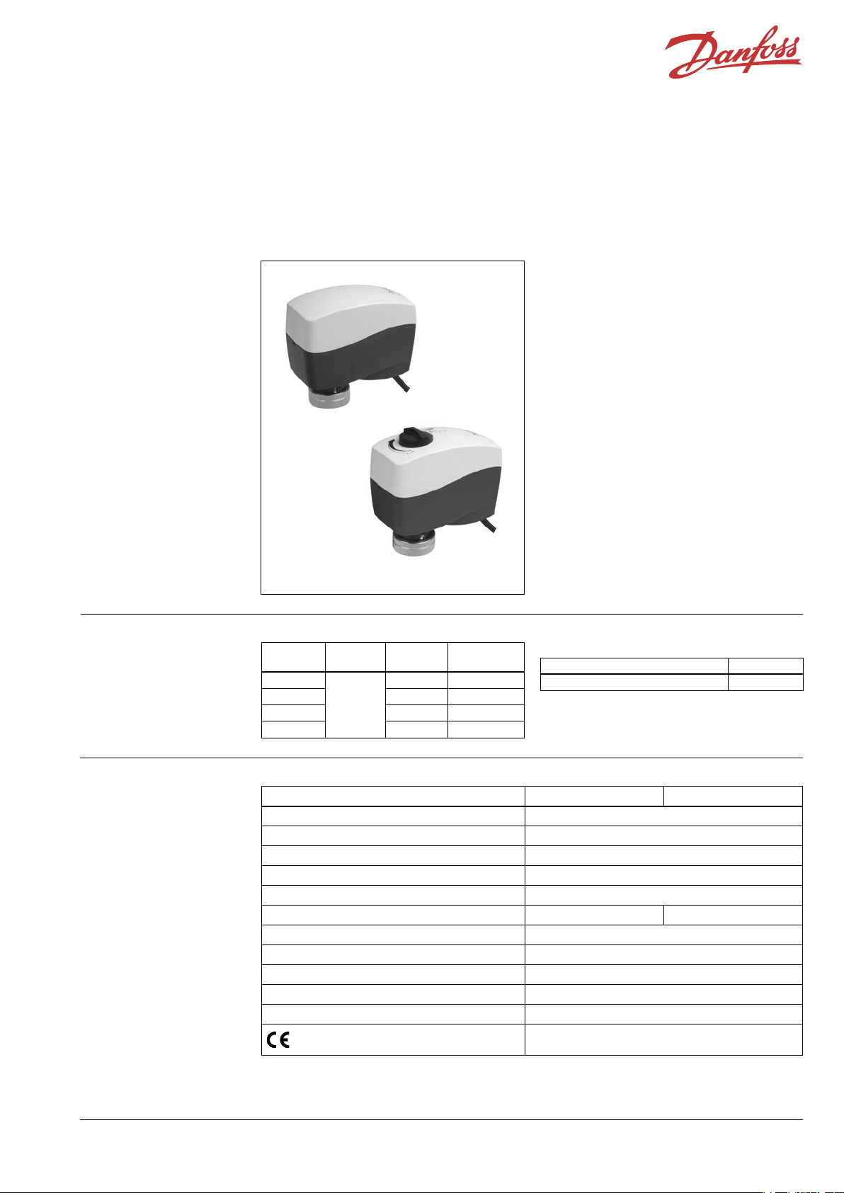
Ordering
Type
Supply
voltage
Speed Code No.
AME 130
24 V~
24 s/mm 082H8044
AME 140 12 s/mm 082H8045
AME 130H 24 s/mm 082H8046
AME 140H 12 s/mm 082H8047
Technical data
Type AME 130, AME 130H AME 140, AME 140H
Power supply 24 Vac; +10 to –15%
Power consumption 1.3 VA
Frequency 50 Hz/60 Hz
Close of force 200 N
Stroke 5.5 mm
Speed 24 s/mm 12 s/mm
Max. medium temperature inside the pipe 130 °C
Ambient temperature 0 … 55 °C
Storage and transport temperature –40 … +70 °C
Protection code IP 42
Weight 0.3 kg
- marking in accordance with standards
EMC- Directive 89/336/EEC, 92/31/EEC, 93/68/EEC,
EN 61000-6-1 and EN 61000-6-3
Spare parts
Type Code No.
Cable (5 m) 082H8053
AME 130H, AME 140H
AME 130, AME 140
Page 2
2 VD.KG. Z1.02 © Danfoss 06/20 06 DH-SMT/SI
Data sheet Actuators for modulating control AME 130, AME 140, AME 130H, AME 140H
Data sheet
Installation
Commissioning
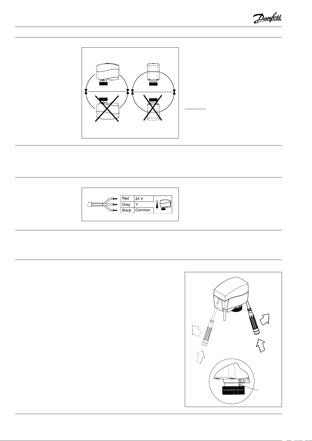
Mechanical
The actuator should be mounted with the valve
stem in either horizontal position or pointing
upwards.
The actuator is fixed to the valve body by means
of a mounting ring which requires no tools for
mounting. The ring should be tightened by
hand.
Electrical
Important: It is strongly recommended that the
mechanical installation is completed before the
electrical installation.
Each actuator is supplied with the connecting
cable for the controller.
The factory setting of the spindle is the fully
stem up position because of easier mechanical
connection of the actuator on the valve.
Wiring
1 Check the valve’s neck. The actuator should
be in steam up position (factory setting).
Ensure that the actuator is mounted securely
on valve body.
2 Energise the actuator according to the wiring
diagram - see page 2.
3 The direction of stem movement can be
observed on the positon indicator.
Installation procedure
Disposal The actuator must be dismantled and the
elements sorted into various material groups
before disposal.
position
indicator
Page 3

DH-SMT/SI VD.KG. Z1.02 © Danfoss 06/20 06 3
Data sheet Actuators for modulating control AME 130, AME 140, AME 130H, AME 140H
DIP Switch Setting
(for service purposes only)
The actuator has a function selection DIP switch
under the removable cover.
The switch provides the following functions:
• SW1:
Reset
Changing this switch position will cause the
actuator to go through a self stroking cycle.
• SW2:
0/2 - Input signal range selector
If set to OFF position, the input signal is in the
range from 2 V … 10 V (voltage input) or from
4 mA … 20 mA (current input). If set to ON
position, the input signal is in the range from
0 V … 10 V (voltage input) or from
0 mA … 20 mA (current input).
• SW3:
D/I - Direct or inverse acting selector
If set to OFF position, the actuator is direct
acting (stem lowers as voltage increases). If
the actuator is set to ON position, the actuator
is inverse acting (stem raises as voltage
increases).
• SW4:
---/Seq - Normal or sequential mode
selector:
If set to OFF position, the actuator is working
in range 0(2)..10V or 0(4)..20mA. If set to ON
position, the actuator is working in sequential
range; 0(2)..5 (6)V or (0(4)..10 (12)mA) or
(5(6)..10V) or (10(12)..20mA).
• SW5:
0 … 5 V/5 … 10 V - Input signal range in
sequential mode:
If set to OFF position, the actuator is working
in sequential range 0(2)..5 (6)V or 0(4)..10 (12)mA.
If set to ON position, the actuator is working
in sequential range; 5(6)..10V or 10(12)..20mA.
• SW6:
U/I - Input signal type selector
If set to OFF position, voltage input is
selected. If set to ON position, current input is
selected.
Manual override
(for service purposes only)
AME 130, AME 140
1 Remove the cover.
2 Insert the Allen key 6 into the spindle.
3 Press and hold the button (on the bottom
side of the actuator) during manual override.
4 Pull out the tool.
5 Place cover back on the actuator.
Caution:
Do not manually operate the
drive under power!
Remark:
A ”click” sound after energizing the actuator
means that the gear wheel has jumped into
normal position.
If manual override has been used, then Y
signal is not correct until the actuator reaches
it’s end position. If this is not accepted, reset
the actuator.
push
Page 4

4 VD.KG. Z1.02 © Danfoss 06/20 06 DH-SMT/SI
Data sheet Actuators for modulating control AME 130, AME 140, AME 130H, AME 140H
AME 130H, AME 140H
1 Press and hold the button (on the bottom
side of the actuator) during manual override.
Remark:
A ”click” sound after energizing the actuator
means that the gear wheel has jumped into
normal position.
Manual override (continuous)
AME 130(H) / 140(H) +
VZ 3, VZL 3
AME 130(H) / 140(H) +
VZ 4, VZL 4
AME 130(H) / 140(H) +
VZ 2, VZL 2
AME 130(H) / 140(H) +
VRBZ 2/3
Dimensions
AME 130, AME 140 AME 130H, AME 140H
Actuator - valve
combinations
 Loading...