

Page 1
Data sheet
Actuator 2 point, ON/OFF control
AMI 120 NL-1
Description
The AMI 120 NL-1 is a 2 point (ON/ OFF), 3
wire actuator used with the AB-QM pressure
independent control valves installed on hot or
chilled water system applications. This actuator is
installed on AB-QM valve sizes ranging from 1/2”
to 1- 1/4”. The AB-QM assembly is suitable for
installation within fan coil units, VAV, induction
units or additional units that require combined
balancing and valve control, which could be
located within enclosures or plenum rated
spaces.
As a 3 wire actuator, it receives constant power to
travel to its default position and upon receipt of
input signal will travel in the opposite direction.
Designed within the actuator is an overload and
gap function to prevent unnecessary travel from
the actuator.
Main data:
• 2-point, ON/ OFF, 3 wires required
• Force switch-off at stem down position
prevents overload of actuator and valve
• Gap function detection on stem up travel
• No tools required for mounting
• Maintenance free during lifetime
• Low noise operation
• 1/2” Conduit hole, removable plate
• Wiring terminal block
• In accordance with UL 2043 for plenum
installation
• UL listed
Ordering
Technical data
Typ e Supply voltage Speed Code No.
AMI 120 NL-1 24VAC 10 s/mm @ 60Hz (12 s/mm @ 50Hz) 082H5003
Power supply V 24 AC; +10%... -15%
Electrical Connection ” 1/2 electrical conduit, wiring terminal block
Power consumption VA 1 VA
Frequency Hz 50 / 60
Control Input ON/OFF, 3-wire
Output Signal End travel position feedback
Actuator Force lbf (N) 45.0 (200)
Max. Stem Travel mm 5
Travel Speed 12s/mm @ 50Hz, 10s/mm @ 60Hz
Max. Medium Temperature
Ambient temperature 32 to 131 (0 to 55)
Humidity 5 to 95% RH, noncondensing
Weight lb (kg) 0.66 (0.3)
USA
C US
Canada
Europe
°F (°C)
UL Listed , CCN XABE, File E480529 ; to ANSI/UL 60730-1 and ANS I/ UL 60730-2-14
Investig ated and approved f or plenum use in accor dance with UL 2043
UL listed , CCN XABE7, File E48029; to CAN/CSA -E60730-1:13 and CAN/CS A-E60730-2-14:13
CE Mark - Danf oss declares that t his product comp lies with all relev ant CE-marking
directives
24 8 (120)
© Danfoss | 2018.01
VD.HU.Z1.22 | 1
Page 2
Data sheet Actuator for two point control AMI 140
1 3
42
1 3
42
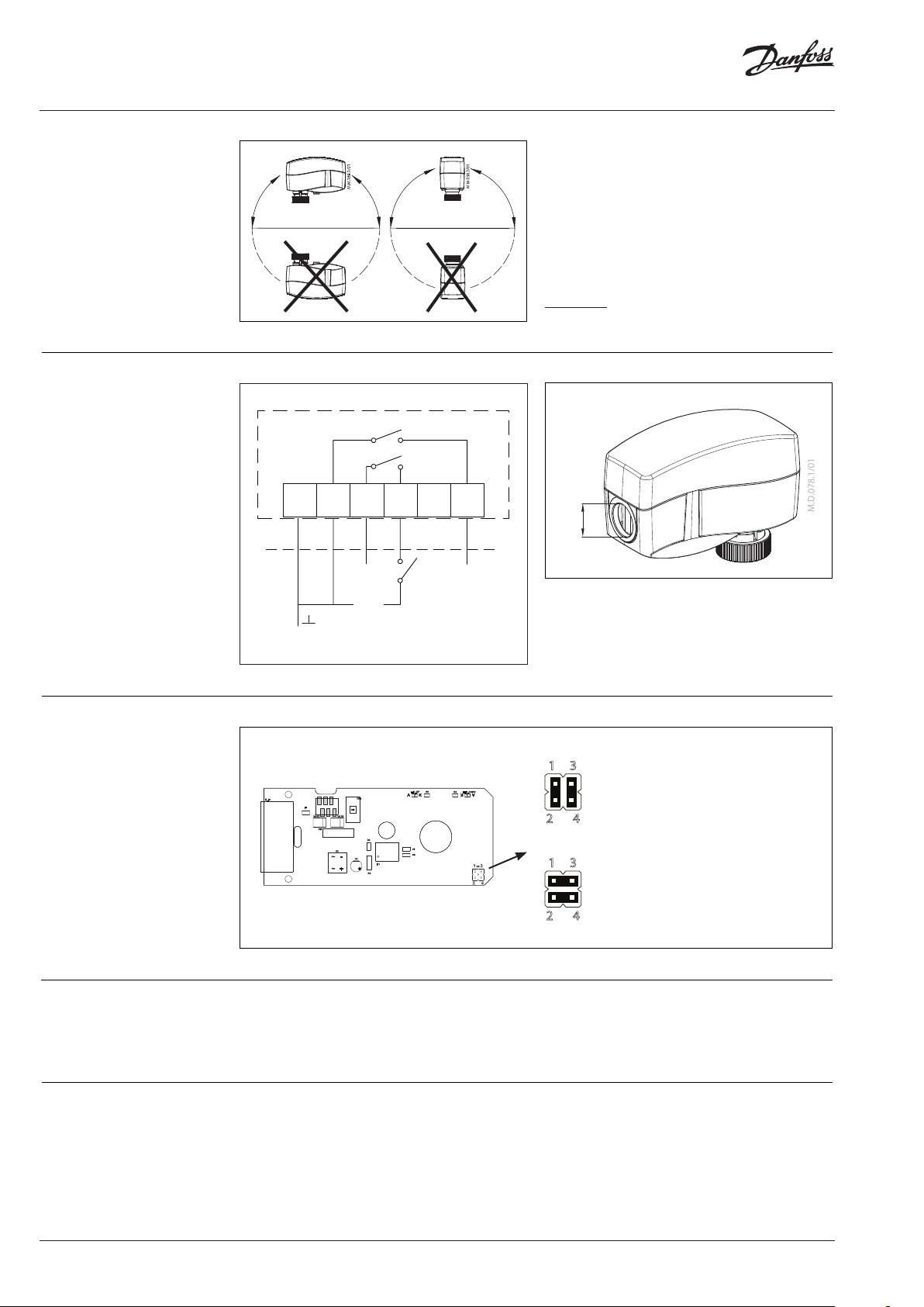
Installation Mechanical
The actuator should be mounted with the valve
stem in either horizontal position or pointing
upwards.
The actuator is xed to the valve body by means
of a mounting ring which requires no tools for
mounting. The ring should be tightened by hand.
Electrical
Important: Prior to energizing the actuator
should be assembled to the AB-QM.
Wiring
AMI 120 NL-1
SN SP 4 1 5
½”
(Oponal)
~ AC 24V
50/60Hz
(Oponal)
Travel Direction
R5LED_UP
R4 LED_DOWN
C6
C5
F1
VAR1 VAR2
MOTOR
CMa
CM
RM
D4
D3
C3
IC1
R3
Disposal The actuator must be dismantled and the
elements sorted into various material groups
before disposal.
A eld supplied 1/2” trade size electrician’s tting
and lock nut can be mounted to the actuator
enclosure. Insert wiring material through the
removable plug or conduit tting, and wire
connection to the terminal block.
Jumper Pos ition “A” (Factory Set ting)
“On” at term inal block posit ion “1”: Actuator drives
down and va lve closes, optio nal terminal 4
closes.
“Off ” at terminal blo ck position “1”: Actuat or drives up
and valve o pens, optional t erminal 5 closes.
XS1 3
2
4
Jumper Pos ition “B”
“On” at term inal block posit ion “1”: Actuator drives u p
and valve o pens, optional t erminal 4 closes.
“Off ” at terminal blo ck position “1”: Actuat or drives
down and va lve closes, optio nal terminal 5
closes.
Commissioning The factory position of the actuator spindle is in a
full stem up position allowing easier mechanical
connection of the actuator on the valve.
2 | © Danfoss | 2018.01
VD.HU.Z1.22
Page 3
Data sheet Actuator for two point control AMI 140
Installation and
commissioning procedure
(if required)
Do not touch anything on
the PCB! Before removing the
cover in need of hand operation
with Allen key power supply
must be disconnected.
Lethal voltage!
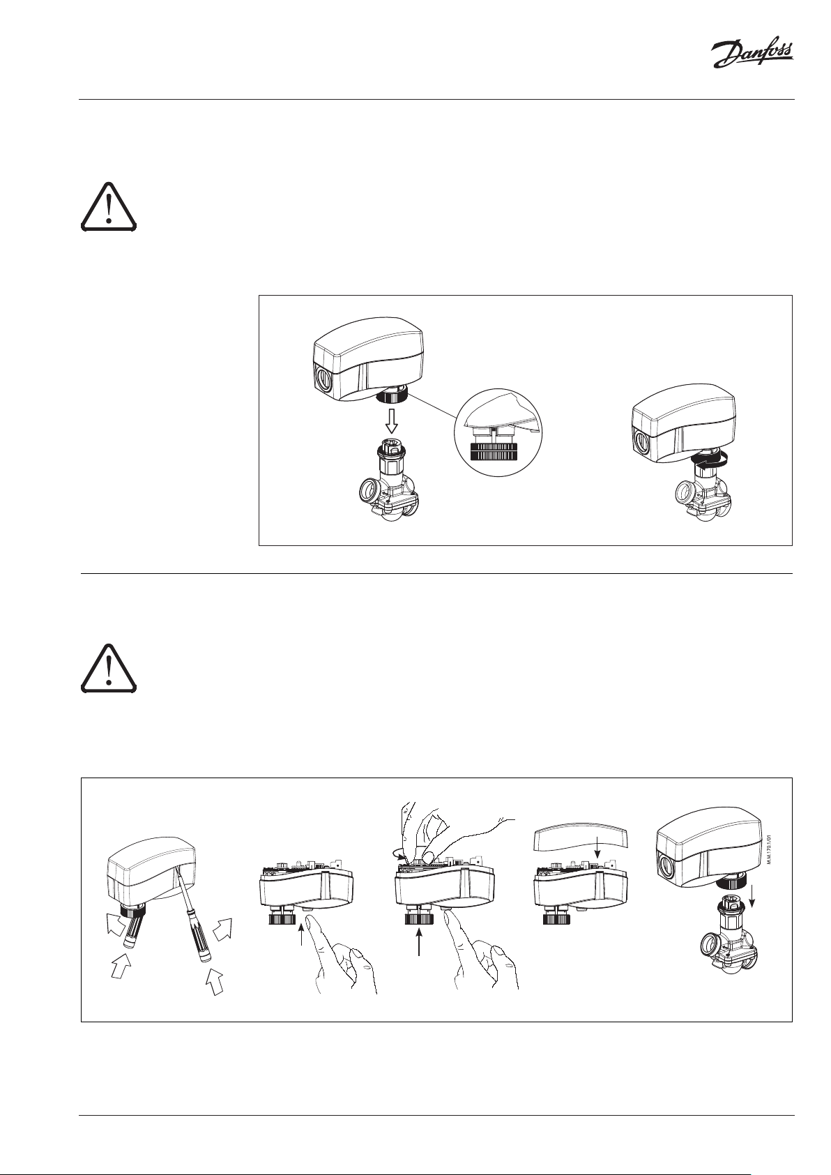
1. Check the valve neck. The actuator should be
in the full up position (factory setting). If it is
not, manually reposition the actuator to its
full up position.
2. The actuator is fixed to the valve body by
means of a ribbed nut which requires no tools
for mounting. The ribbed nut should be hand
tightened only.
‘External position indication
located at the neck of the
motor actuator’
3. For applications requiring conduit, a field
supplied 1/2” trade size electrician’s fitting
and lock nut can mounted in the actuator
enclosure. Make all wiring connections in
accordance with local, national, or regional
regulations.
4. Insert wiring material through the removable
plug or conduit fitting, and connect to
the terminal block according to the wiring
diagram - see page 2.
Manual override
(for service purposes only)
Caution:
Do not manually operate the
drive under power!
②
①
①
• Remove cover ①
• Press and hold the button ② (on the
bottom side of the actuator) during manual
override③
• Replace cover ④
• Install actuator on valve ⑤
Remark:
A ”click” sound after energizing the actuator
means that the gear wheel has jumped into
normal position.
②
VD.HU.Z1.22
© Danfoss | 2018.01 | 3
Page 4

Danfoss
A
11655 Crossroads Circle
Baltimor
T
F
Email: heating
Danf
already on order pr
All trademarks in this material are proper
Data sheet Actuator for two point control AMI 140
Dimensions (mm)
4.66in (118.5mm) 2.09in (53mm)
3. 58in (91mm)
6.16in (156.5mm)
B-QM™ Valves
e, MD 21220 USA
elephone: 1-888-DANFOSS (326-3677), option 3
ax: (416) 352-5981
oss can accept no responsibility for possible errors in catalogues, brochures and other printed material. Danfoss reserves the right to alter its products without notice. This also applies to products
4 | © Danfoss | DHS-SRMT/SI | 2018.01
.cs.na@danfoss.com
ovided that such alterations can be made without subsequential changes being necessary in specications already agreed.
ty of the respective companies. Danfoss and the Danfoss logotype are trademarks of Danfoss A/S. All rights reserved.
VD.HU.Z1.22
 Loading...