

Data sheet
Actuators for modulating control
AME 113 NL SU/SD - with safety function (stem up/down)
AME 113 NLX SU/SD - with feedback signal and safety function
Description
AME 113 is a series of gear actuators for opening
and closing valves for heating and cooling
systems. The predominant area of application
is the energy-efficient control of water-bearing
valves in the area of building services and
automation.
Features • Suitable for AC and DC operation
• Internal energy storage for the safety
function. Positioning in case of supply voltage
failure
• Stroke 8.5 mm or valve path recognition
• Actuating force 125 N
• LC display for status indication
• Function display via LED
• Equal percentage characteristic
• Very fine resolution in valve positioning
• Very short response times
• Max. energy efficiency by means of motor
control via microcontroller
• Self-locking gear in all positions, de-energized
• Antitheft device by removable locking latch
• Special feature for NLX version is feedback signal
• Safety function in case of power failure
The actuator is equipped with a safety function.
If the power supply fails, the valve pressure
plate moves into a parking position. The energy
for this is provided by an internal rechargeable
accumulator.
The actuator has an equal percentage
characteristic, meaning the flow through the
valve is equal percentage to the control signal.
The control is performed by a 0-10 V DC control
signal sent by a central DDC system or a room
thermostat. The current position and the control
voltage are shown on an LC display.
The actuator is supplied with a pluggable
connecting cable and has a manual valve
adjustment which can be used, for example, for
maintenance or installation.
A version with feedback signal is available. The
back channel transmits information about the
current valve position as well as about possibly
occurred errors to the DDC installation.
• Force-dependent deactivation in case of
overload or when the final stop resp. the
closing position is reached
• Manual valve setting
• Very low power consumption
• Valve adapter system
• Simple plug-in installation without tools
• 100 % protection in case of leaky valves (IP 54)
• 360° installation position
• Plug-in connecting cable
• Low-noise and maintenance-free
• High functional safety and long expected
service life
• Control input suitable for 0-10 V
• Automatic valve path recognition / no load
detection
© Danfoss | 2021.08 AI391040222855en-010101 | 1

Data sheet AME 113
Typ e AME 113 NLX SD AME 113 NLX SU AME 113 NL SD AME 113 NL SU
Operating voltage 24 V AC, -10 % ... +20 %, 50-60 Hz 24 V DC, -20 % ... +20 %
Operating power 2.6 VA/ 1.4 W
Charging operating power with battery
(temporarily)
Safety activations / Tag 4
Charging time of int. battery, if empty 16 h
Max. power consumption <160 mA
Standby power consumption <10 mA
Control voltage 0...10 V DC
Working range of the control voltage 0.5...10 V DC
Resistance of control voltage input 100 kΩ
Stroke Max. 8. 5 mm
Actuation force 125 N -20/+40%
Actuation time 15 s/mm
Noise level <30dB/A
LCD (H x W) 10 x 20 mm
LED Multicolour LED
Fluid temperature 0 °C to +100 °C
Storage temperature -20 °C to +70 °C
Characteristic Equal percentage
Ambient temperature 0 °C to +50 °C
Degree of protection IP 54
Protection class III
CE conformity according to EN 60730
Casing
Casing cover
Cable
Dimensions (H x W x D) 65 x 45 x 90 mm
Weight with connection cable (1 m) 155 g
Surge strength according to EN 60730-1 1 kV
Safety function Yes (do wn) Yes (up) Yes (do wn) Yes (up)
Power failure response
Feedback Signal:
1)
In all install ation positions.
Material Polyamide
Colour Signal white (RAL 9003)
Material (polycarbonate)
Colour Transparent
Typ e 4 x 0.22 mm² PVC 3 x 0.22 mm² PVC
Colour white
Length 1 m
Safety function extends the
stem, closes the AB- QM valve
Voltage range 0 - 10 V Output current 1 mA Load impedance 10 kΩ - 1000 kΩ Resolution 0.1 V -
Safety function retrac ts the
stem, opens the AB- QM valve
3.1 VA/ 1.7 W
1)
Safety function extends the
stem, closes the AB- QM valve
Safety function retrac ts the
stem, opens the AB- QM valve
Ordering
Variation
Function
The actuator is available in various versions which differ in their functional features:
LC display
Function display via LED
Valve path recognition
Feedback signal
Manual setting
Safety function display via LED
The actuator mechanism works with a stop motor, a micro controller and a gearing mechanism. After
Typ e Supply voltage Feedback Code no.
AME 113 NLX SD 24 V- AC / DC 0 -10 V 082H5000
AME 113 NLX SU 24 V- AC / DC 0 -10 V 082H5001
AME 113 NL SD 24 V- AC / DC - 082H5007M
AME 113 NL SU 24 V- AC / DC - 082H5008
AME 113 NLX SD AME 113 NLX SU AME 113 NL SD AME 113 NL SU
✓ ✓ ✓ ✓
✓ ✓ ✓ ✓
✓ ✓ ✓ ✓
✓ ✓
✓ ✓ ✓ ✓
✓ ✓ ✓ ✓
switching on the power supply, the actuator carries out an initialization. In the initialization phase, the
traverse path is determined; in the display, alternately “In” (for initialization) and the applied control
voltage are shown. For further descriptions on initialization, refer to the chapter on the actuator.
2 | AI391040222855en-010101 © Danfoss | 2021.08
Data sheet AME 113
valve travel = 100 %
MPR 46845
actuator travel in %
Control
Initialization
Operation
First the valve pressure plate is completely
retracted; the upper end stop of the actuator
is determined by this. The valve pressure plate
then extends completely and determines the
lower end stop, the closing point of the valve.
Subsequently the actual valve path recognition
is performed. For this, the valve pressure plate
retracts at high speed and extends again slowly.
The valve travel is detected during this process.
If the actuator does not detect the valve path,
control is performed using the parameterized
stroke (factory setting: 8.5 mm).
The AME 113 actuator is controlled via a 0-10 V
DC control signal from a room thermostat or a
building management system. The control signal
allows a precise activation and positioning of the
actuator.
Note:
1. For poppet valves with a soft rubber seal, the
compression of the rubber seal is detected as
the valve path.
2. The following diagrams only apply when the
appropriate valve adapter ring is used:
Due to different conditions, the valve travel
for the actuator can change in practice. The
valve has been readjusted or the actuator has
been mounted on a new valve. In both cases,
the values determined during initialization will
change. In order for the actuator to adjust to
the new valve path, the voltage supply and the
control voltage must be interrupted briefly. After
the power supply has been switched on again, a
new initialization phase is carried out.
Note:
The AME 113 needs a maximum of 15 min for an
initialization phase.
100
0
12345678910
UST in V
active voltage control range
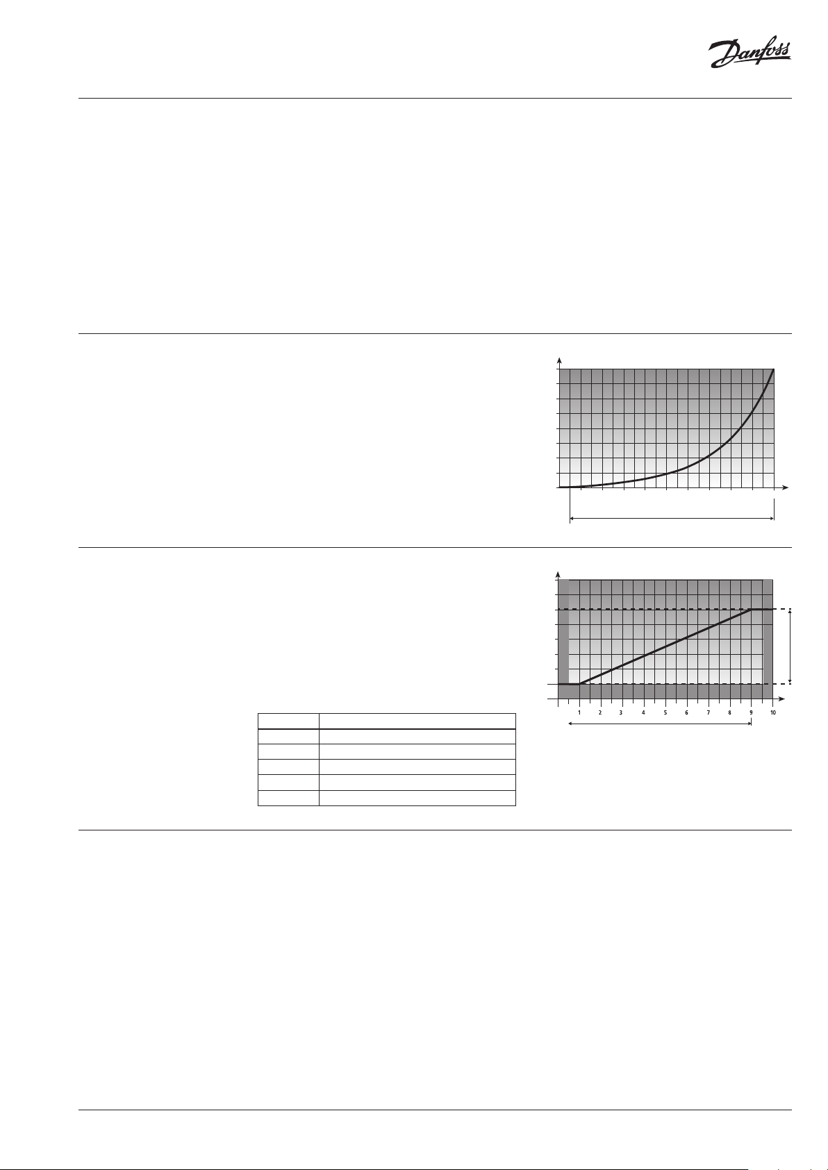
Optional feedback signal
(AME 113 NLX)
The 0-10 V feedback signal of the actuator
enables direct feedback of the current operating
status to the DDC system. Voltages of 1-9 V
provide information about the actuator position.
Voltages <0.5 V and >9.5 V signal any errors
that may occur. The connection of the feedback
signal is volt-age resistant up to 24 V. It outputs
a voltage proportional to the actuator position,
contact error
Stroke in %
actuator error
which is made available to the DDC system.
Safety function
Voltage Description
< 0.5 V No function or no contacting
1-9 V Voltage emitted proportionally to the stroke
1 V Corresponds to a closed valve
9 V Corresponds to an open valve
>9.5 V Internal error
The electronic system of the actuator
continuously monitors the supply voltage. If this
fails for >= 2 seconds, the valve spindle moves
to the specified parking position and closes e. g.
In the event of a power failure during the
initialization phase, the drive stops the
initialization and then moves to the parking
position.
U
the valve. The actuator remains in this parking
position until an operating voltage is applied
again.
• The internal energy storage may only have a small residual charge after longer storage.
• The internal energy storage is designed for at least 4 power failures per day.
• The charging time for a completely empty energy storage is 16 hours.
• When the operating voltage is applied to the failsafe drive again, it starts initialization, see
paragraph Initialization.
• A short start-up can trigger a failsafe event. The valve pressure plate extends and the actuator can
no longer be mounted. In this case, retract the valve pressure plate manually. See paragraph Manual
valve setting.
• Perform the commissioning of the valve.
AI391040222855en-010101 | 3© Danfoss | 2021.08

Data sheet AME 113
5
Function display via LED
Manual valve setting
IP 54
For function signalling of operating statuses, the actuator has two multi-coloured LEDs. Green and
red are used as signal colours.
LED 1
LED 2
55%55%
LED 1 Description
Green (flashes) Initialisation
Red Error1
LED 2 Description
Green (flashes)
Green Device ready
Orange
Red Error1
Failsafe operation, parking
position is approached
Ready for operation, battery
is charging
The manual valve setting allows to bring the valve pressure plate to the desired position in deenergised status. This facilitates e. g. maintenance and installation.
4
Remove the
protective plug and
the connection line,
or switch off the
voltage supply.
LC display
Dimensions
Introduce a
screwdriver (0.3 x 2
mm) into the manual
valve setting device.
When turning to
the right, the valve
pressure plate is
retracted; turning to
the left extracts it.
Note: When the stop
is reached, turn back
by 1/4.
Note
Pull the plug for manual setting. Then wait for
the fail-safe function to end until LED 2 (green)
goes out. See also the chapter “Function
display via LED”.
The LC display alternatively shows the setting
position and the applied control voltage. In case
of a control requirement, the current driving
direction is shown in the LC display by means of
an arrow. In case of an error, the corresponding
error code is shown and the error is indicated by
a steadily lighted LED.
Remove the
screwdriver after
reaching the desired
Install the protective
plug and connect the
connection line.
position.
1)
In case of erro r: Disconnect from voltag e, keep voltage free for
20 minutes and the n reconnect. If this occurs m ore than once,
replace the device.
55%
4 | AI391040222855en-010101 © Danfoss | 2021.08

Data sheet AME 113
4
Electrical connection 24 V
AC/DC L1 (+) L2 (-)
Installation position
AME 11 3
The actuator is controlled via a 0-10 V control unit
or a building management system.
The actuator can be operated in any installation position.
Connection line
We recommend the following maximum
cable lengths for installing a 24 V system:
Cable Section Length
Standard DDC
line
J-Y(ST )Y 0.8 mm² 45 m
NYM / NYIF 1.5 mm ² 136 m
0.22 mm² 20 m
Transformer/power supply unit:
A safety isolating transformer according to
EN 61558-2-6 or a switching power supply
according to EN 61558-2-16 must always be
used.
The dimensioning of the transformer or the
switching power supply results from the
maximum making capacity of the actuators.
Installation with valve
adapter
Note:
The AME 113 needs a
maximum of 15 min for an
initialization phase.
vertical horizontal “overhead”
ATTENTION!
Installation with extracted valve pressure plate
leads to actuator damage.
• Only install the actuator with completely
retracted valve pressure plate.
• Retract an extracted valve pressure plate with
the manual valve setting, or electrically.
Screw the valve
adapter manually
onto the valve.
Position the actuator
manually in vertical
position to the valve
adapter.
The actuator is mounted on the valve using a
valve adapter. The actuator is simply plugged
onto the valve adapter previously installed
manually. The fact that the valve pressure plate is
retracted in factory, allows for easy installation.
Simply latch the
actuator to the valve
Connect the connection
line to the actuator.
adapter manually
by applying vertical
pressure; a clicking
sound can be heard.
AI391040222855en-010101 | 5© Danfoss | 2021.08

Data sheet AME 113
Error codes
Anti-theft device
Certificates
Queued errors are indicated by an error code.
Error code Description Error correction
E8 Indicates an internal error.
The actuator is secured against disassembly by
unauthorised persons by simply removing the
locking button.
The AME 113 has NRTL approval by
TÜV Süd.
The actuator performs a re-initialisation
after 10 seconds. If the error cannot
be eliminated automatically after
a maximum of three attempts, the
indication will become steady. In this
case the customer ser vice must be
called.
ІМПОРТЕР:
UA: ТОВ з ІІ «Данфосс ТОВ», вул. Вікентія Хвойки, 15/15/6, м. Київ, 04080, Україна
© Danfoss | DCS-S/SI | 2021.086 | AI391040222855en-010101
 Loading...