

Data sheet
Actuators for modulating control
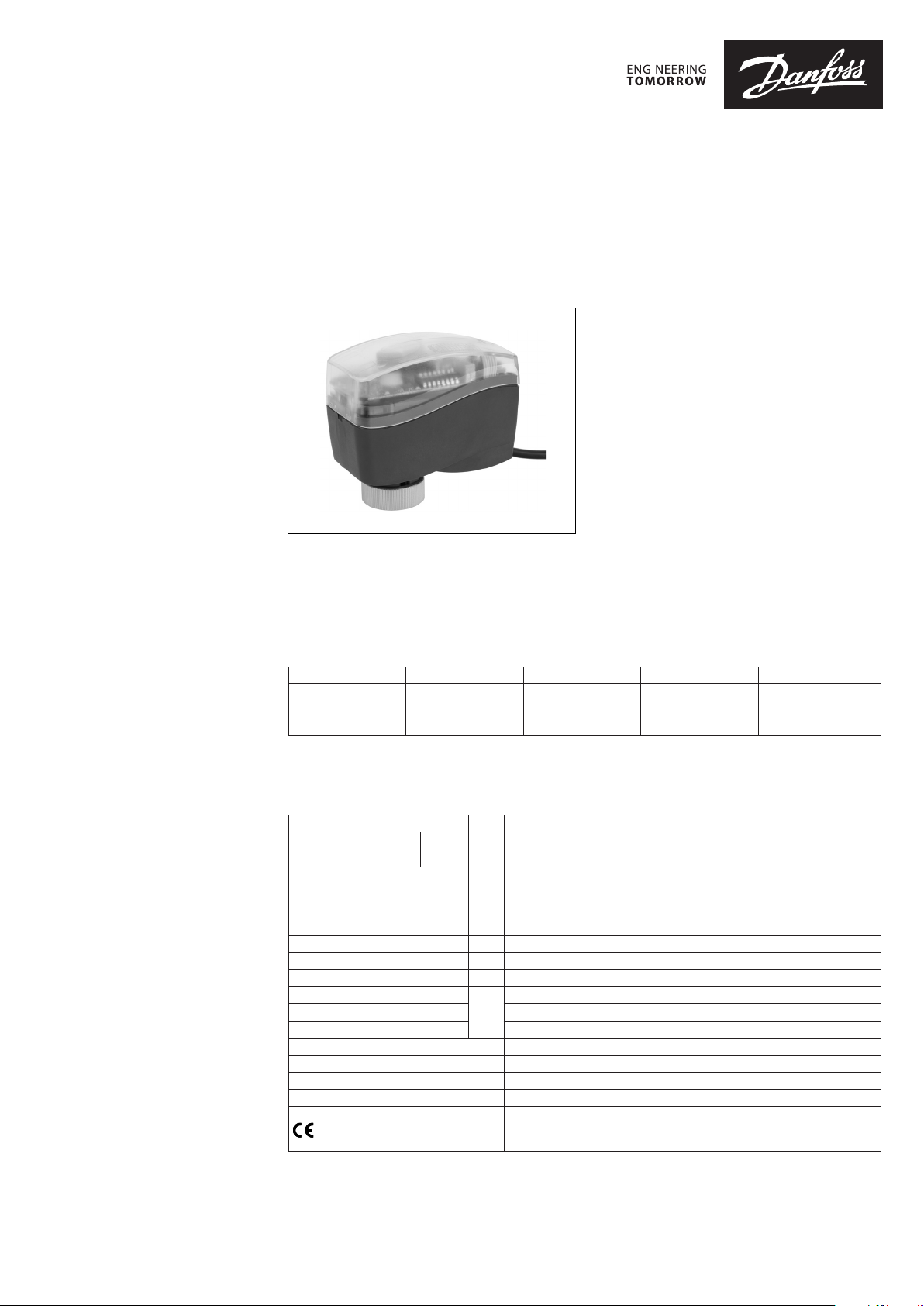
AME 110NLX - with position feedback signal
Description
Ordering
The actuator can be used with fan coil units,
induction units, small reheaters, recoolers and
zone applications in which hot/cold water is the
controlled medium.
Main data:
• Position feedback or output signal
(X=0-10 VDC)
• Gap detection at stem up position
• Modulating control
• Force switch-off at stem down position
prevents overload of actuator and valve.
• No tools required for mounting
• Maintenance-free lifetime
• Low-noise operation
• Self-positioning process
The actuators are used together with
• Halogen free cables
automatically balanced combination valve type
AB-QM for DN 10 to DN 32.
Typ e Supply voltage Speed Cable length Code No.
1,5 m 082H8060
AME 110 NLX 24 V~ 24 s/mm
Note: Package of actu ators is Single Pack - each actua tor is packed in separate box.
5,0 m 082H8062
10 m 082H8064
Technical data
© Danfoss | 2019.05
Power supply V 24 ±20 %; AC
Power consumption
Frequency Hz 50/60
Control input Y
Control output X V 0-10 R o
Closing force N 130
Stroke mm 5
Speed s/mm 24
Max. medium temperature
Ambient temperature 0 … 55
Storage and transport temperature –40 … 70
Ambient humidity 95% r.h., non-condensing
Protection class III safet y extra-low voltage
Grade of enclosure IP 42
Weight 0,3 kg
- marking in accordance with standards
running VA 1,5
standby W 0,4
V 0-10 (2-10) Ri = 200 kΩ
mA 0-20 (4-20) Ri = 500 Ω
(min)
120
°C
Low Voltage Directive 2014/35/EU, EN 60730-1:2011, EN 60730 -2-14:1997 +
A1:2001 + A11:2005 + A2:2008
EMC Directive 2014/30/EU, EN 61000-6-2:2005, EN61000 -6-3:2007 + A1:2011
= 38 kΩ
VD.HU.M3.02 | 1
Data sheet AME 110NLX
Installation
Installation procedure
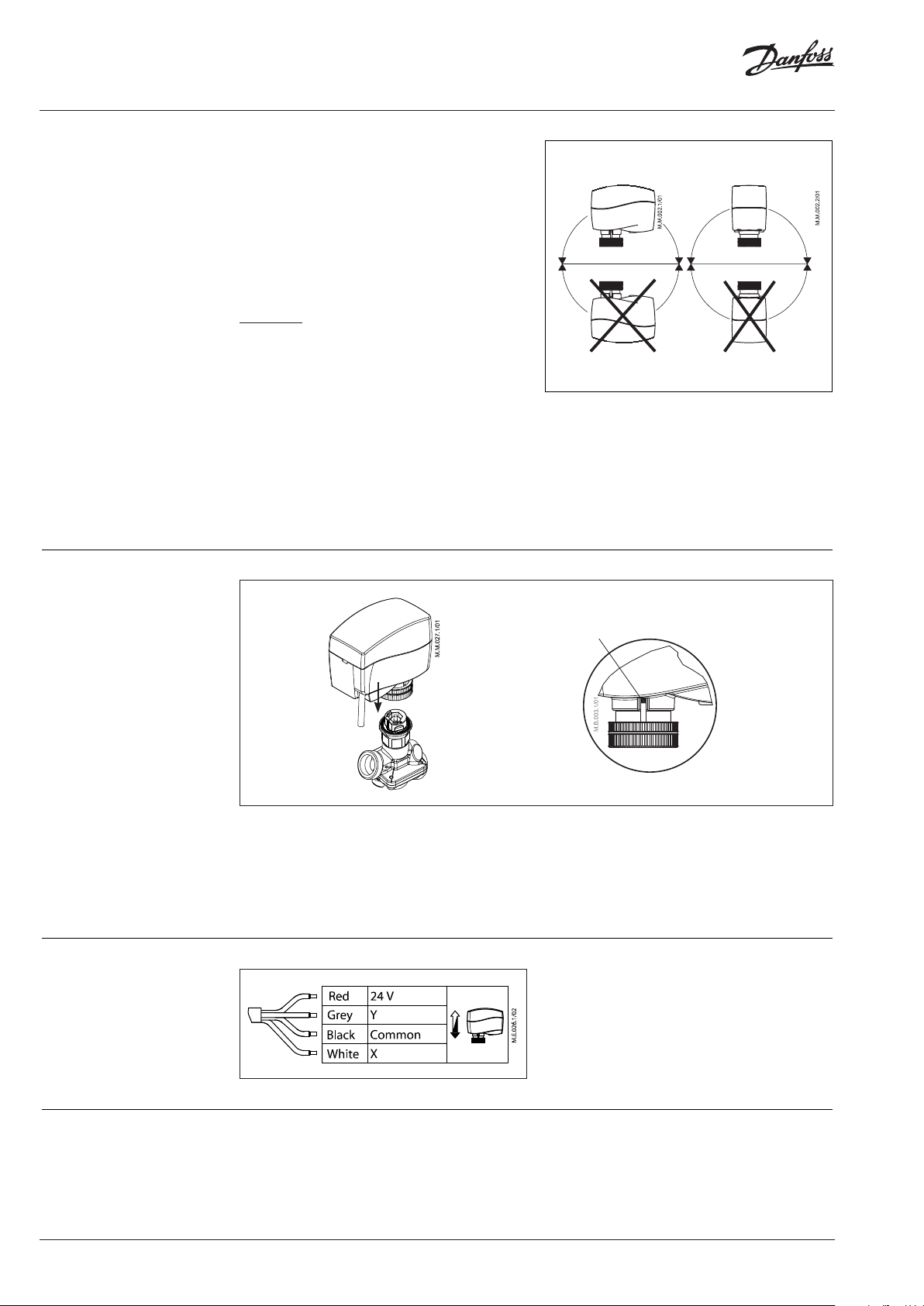
Mechanical
The actuator should be mounted with the valve
stem in either horizontal position or pointing
upwards.
The actuator is fixed to the valve body by means
of a mounting ring, which requires no tools for
mounting. The ring should be tightened by
hand.
Electrical
Important: It is strongly recommended that the
mechanical installation is completed before the
electrical installation.
Auto sleep mode
1. If actuator AME 110NLX is charged by 24 V
supply voltage and if it is not installed on
AB-QM valve, it will stop in lower position and
switch off all LED indicators after 5 minutes.
2. It is mandatory to drive the spindle of the
actuator to upper position before it will be
installed on AB-QM valve (please refer to
manual override drawings)!
3. Auto sleep mode switches back to learning
mode by pressing RESET button or by cycling
power supply.
Each actuator is supplied with the connecting
cable for the controller.
Wiring
1. Check the valve neck. The actuator should be
in stem up position (factory setting).
Ensure that the actuator is mounted securely
on the valve body
position
indicator
2. Wire the actuator according to the
wiring diagram
3. The direction of the stem movement can be
observed on the position indicator
Commissioning
2 | © Danfoss | 2019.05
The factory setting of the spindle is the fully
stem up position because of easier mechanical
connection of the actuator on the valve.
VD.HU.M3.02

Data sheet AME 110NLX
DIP Switch Setting
(for service purposes only)
The actuator has a function selection DIP switch
under the removable cover.
The switch provides the following functions:
• SW1:
0/2 - Input signal range selector
If set to OFF position, the input signal is in the
range from 2-10 V (voltage input) or
from 4-20 mA (current input).
If set to ON position, the input signal is in the
range from 0-10 V (voltage input) or from
0-20 mA (current input).
• SW2:
D/I - Direct or inverse acting selector
If set to OFF position, the actuator is direct
acting (stem contracts as voltage increases). If
the actuator is set to ON position, the actuator
is inverse acting (stem extracts as voltage
increases).
• SW3:
---/Seq - Normal or sequential mode
selector:
If set to OFF position, the actuator is working
in range 0(2)-10 V or 0(4)-20 mA.
If set to ON position, the actuator is working
in sequential range; 0(2)-5(6) V or (0(4)-10(12)
mA) or (5(6)-10 V) or (10(12)-20 mA).
• SW4:
0-5 V/5-10 V - Input signal range in
sequential mode:
If set to OFF position, the actuator is working
in sequential range 0(2)-5(6) V or 0(4)-10(12) mA.
If set to ON position, the actuator is working
in sequential range; 5(6)-10 V or 10(12)-20 mA.
• SW5:
LIN/LOG - Linear or equal percentage flow
through valve selector
If set to OFF position, the flow through the
valve is equal percentage-wise equals the
control signal.
If set to ON position, the flow through the
valve is linear in accordance to the control
signal.
• SW6:
---/ASTK - Anti-blocking function
Exercises the valve to avoid blocking in
periods when the heating/cooling is off.
If set to ON position (ASTK), the valve motion
is switched on. The actuator opens and closes
the valve every 7 days.
If set to OFF position (---), the function is
disabled.
• SW7:
U/I - Input signal type selector
If set to OFF position, voltage input is
selected. If set to ON position, current input is
selected.
Note:
The reset but ton ① will cause the actuator to g o through a self
stroking c ycle (press it for 2 s).
Remark:
When the manua l override has been used, the o utput signal (X) is
not correct unti l the actuator reaches its e nd position.
0-10 V
INV
SEQ
5-10 V
LOG
ASTX
I
ON
OFF
---
DIR
2-10 V
U
---
LIN
0-5 V
Disposal The actuator must be dismantled and the
elements sorted into various material groups
before disposal.
Reset
①
VD.HU.M3.02
© Danfoss | 2019.05 | 3

Danf
already on order pro
All trademarks in this material are property of the respec
Data sheet AME 110NLX
Manual override (for service purposes only)
①
④
Caution:
Do not manually operate the
drive if power is connected!
Do not dismount the actuator
from the valve when it is in a
stem down position!
If dismounted in a stem down
position, there is a high risk
that the actuator gets stuck.
②
⑤
• Remove cover ①
• Press and hold the button ② (on the
bottom side of the actuator) during manual
override ③
• Replace cover ④
• Install actuator on valve ⑤
③
Remark:
A ‘click’ sound after energising the actuator
indicates that the gear wheel has jumped into
normal position.
If manual override has been used, the Y
signal will not be correct until the actuator
has reached its end position. If this is not
accepted, reset the actuator.
Dimensions
oss can accept no responsibility for possible errors in catalogues, brochures and other printed material. Danfoss reserves the right to alter its products without notice. This also applies to products
vided that such alterations can be made without subsequential changes being necessary eady agreed.
4 | © Danfoss | DHS-SRMT/SI | 2019.05
92
68
88
tive companies. Danfoss and the Danfoss logotype are trademarks of Danfoss A/S. All rights reserved.
50
VD.HU.M3.02
 Loading...