

Data sheet
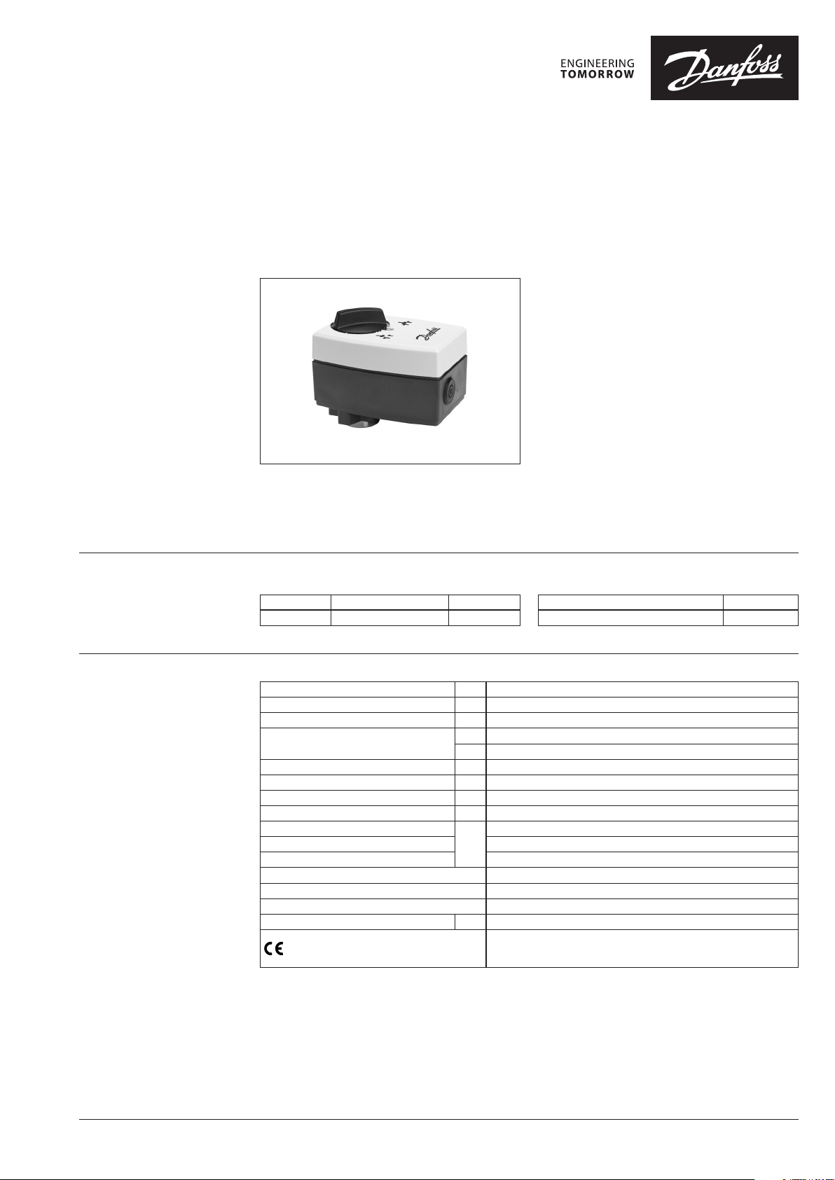
Modulating controlled actuator
AME 11
Description
Ordering
Technical data
In addition to basic function such as manual
control and position indication, the actuators are
also equipped with force sensitive switch-off to
ensure that actuators and valves are not exposed
to overloading.
Main data:
• Nominal voltage: 24 Vac
• Force: 300 N
• Speed: 7 s/mm
• Max. medium temperature:
130 °C + adapter (150 °C)
• End-position signals
The actuator is available for the modulating
controllers with the control Y signal. It is used
with VS2, VM2, VB2, VMV and AVQM valves.
Actuators
Typ e Supply voltage Code No.
AME 11
Power supply Vac 24; +10 to –15 %
Power consumption VA 4.4
Frequency Hz 50/60
Control input Y
Output signal X Vdc 0 -10 (2-10)
Closing force N 300
Max. stroke mm 7
Speed s/mm 7
Max. medium temperature
Ambient temperature 0 … 55
Storage and transport temperature –40 … 70
Ambient humidity 5-95 % r.h., non-condensing
Protection Class II
Grade of enclosure IP 54
Weight kg 0.6
- marking in accordance with standards
24 V
082G3034
Vdc 0-10 (2-10) Ri = 24 kΩ
mA 0-20 (4-20) Ri = 500 Ω
°C
Low Voltage Directive (LVD) 2014/35/EU: EN 60730-1, EN 60730-2-14
Electromagnetic Compatibility Directive (EMC) 2014/30/EU:
EN 61000-6-2,EN 61000-6-3
Note:
The use of AME ac tuators together with V S2 DN 15 is not
recommenda ble. Linear character istics as in VS2 DN 15 valves is
not recommendable in DHW production.
Accessories
Typ e Code No.
High temperature adapter (150°C) 065Z 7547
130 ( 150 with adapter)
© Danfoss | 2018.12 VD.AB.K6.02 | 1
Data sheet AME 11
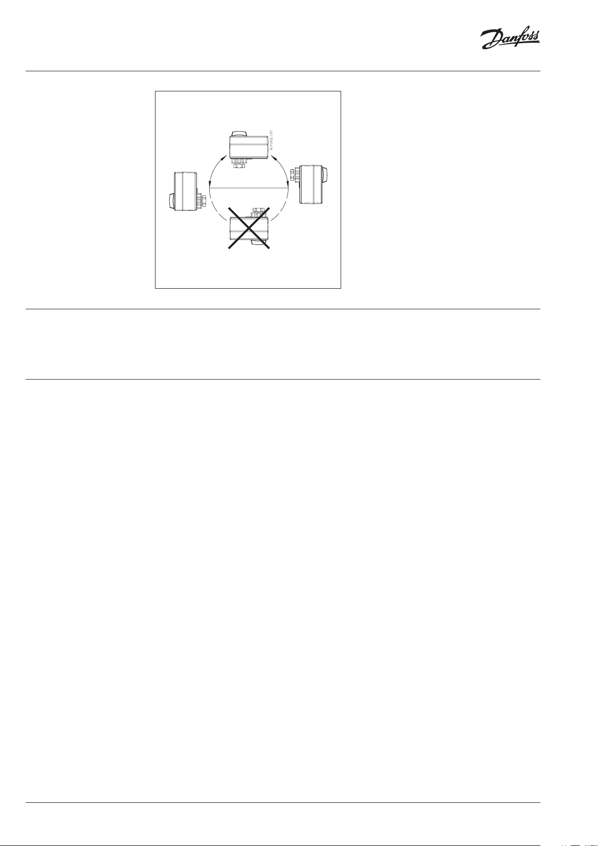
Installation
Disposal The actuator must be dismantled and the
elements sorted into various material groups
before disposal.
Mechanical
The actuator should be mounted with the valve
stem in either horizontal position or pointing
upwards.
The actuator is fixed to the valve body by means
of a mounting ring, which requires no tools for
mounting. The ring should be tightened by
hand.
Electrical
Important: It is strongly recommended that the
mechanical installation is completed before the
electrical installation.
Note: Two cable entries are provided for M 16×1.5
cable glands. One entry is provided with a rubber
grommet. Note that in order to maintain the
enclosure’s IP rating, appropriate cable glands must
be used.
Commissioning
Complete the mechanical and electrical
installation and perform the necessary checks
and tests:
• Isolate control medium. (e.g. self-adjusting
in a steam application without suitable
mechanical isolation could cause a hazard).
• Apply the power. Note that the actuator will
now perform the self-adjusting function.
• Apply the appropriate control signal and
check the valve stem direction is correct for
the application.
• Ensure that the actuator drives the valve over
its full stroke, by applying the appropriate
control signal. This action will set the valve
stroke length.
The unit is now fully commissioned.
Commissioning / testing feature
The actuator can be driven to the fully open or
closed positions (depending on valve type) by
connecting SN to terminals 1 or 3.
2 | VD.AB.K6.02 © Danfoss | 2018.12
Data sheet AME 11
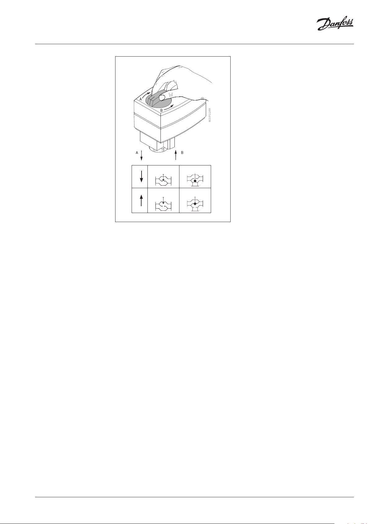
Manual Override
The manual override is achieved by turning the
manual knob to the required position.
Observe the direction of rotation symbol.
If manual override has been used then X and Y
signal are not correct until the actuator reaches
its end position. If this is not accepted reset the
actuator.
• Disconnect power supply
• Adjust valve position using control knob
• Set valve to closed position
• Restore power supply
CLOSE OPEN
A
OPEN CLOSE
B
VD.AB.K6.02 | 3© Danfoss | 2018.12

Data sheet AME 11
DIP switch setting
I
0 …--- V
Inverse
Sequential
5(6) … 10 V
U
- - -
Direct
2 …--- V
0(2) … 5(6) V
3 point/RL
Proportional
Reset
LIN fl ow
Red . Kvs
Reset
LOG f low
100 % Kvs
The actuator has a selection of DIP switches
under the removable cover.
The switch provides the following functions:
DIP1: U/I - Input signal type selector:
• If set to OFF position, input signal Y is set to
voltage (Y).
If set to ON position, input signal Y is set to be
current (mA).
DIP2: 0/2 - Input signal range selector:
• If set to OFF position, the input signal is in the
range from 2 V to 10 V (voltage input) or from
4 mA to 20 mA (current input). If set to ON
position, the input signal is in the range from
0 V to 10 V (voltage input) or from 0 mA to 20
mA (current input).
DIP3: D/I - Direct or inverse acting selector:
• If set to OFF position, the actuator is direct
acting (actuator’s stem extends by voltage
increase). If actuator is set to ON position the
actuator is inverse acting (actuator’s stem
retracts by voltage increase).
DIP4: —/Seq - Normal or sequential mode
selector:
• Two actuators can be set to work parallel with
one control signal. If the SEQUENTIAL is set
than an actuator responds to split control
signal (see 0(2) V … 5(6 V) / 5(6) V … 10 V).
NOTE: This combinatio n works in combination with D IP 5:
0(2)V… 5(6 V) / 5(6) V … 10 V
DIP5: 0-5 V/5-10 V - Input signal range in
sequential mode:
• This function is available if switch
DIP4:---/Sequential is set. Actuator can be
set to match the range of the control signal:
2 … 6 V (DIP 2: 2 V … 10)
0 … 5 V (DIP 2: 0 V … 10)
4 … 12 mA (DIP 2: 2 V … 10)
0 … 10 mA (DIP 2: 0 … 10)
OR
6 … 10 V (DIP 2: 2 V … 10)
5 … 10 V (DIP 2: 0 V … 10)
12 … 20 mA (DIP 2: 2 V … 10)
10 … 20 mA (DIP 2: 0 … 10)
DIP6: Prop./3-pnt - Modulating or 3-point
mode selector:
Actuator can operate in modulating (DIP 6
to OFF) or in “simple” 3-point mode, if the
3-point function is selected (DIP 6 to ON).
Modulating mode; DIP 6 set to OFF
(factorysetting)
• After the actuator has been connected to
power supply, the actuator will start the
self-adjustment procedure. The indicator LED
flashes until self-adjustment is finished.
• Actuator’s stem will run to its totally extended
or retracted position by bridging SN signal
to terminals 1 or 3 and will remain in this
positron as long as potential is present.
It is not allowed to bridge SP to terminal 1
or 3 when DIP 6 is set to OFF .
3-point mode; DIP 6 set to On
Look carefully wiring diagrams as wiring is
different for controllers with triacs output
(ECL) in comparison to controllers with
relay output.
• Connect SN (Neutral) and power supply
(24Vac) via controller to terminals 1 or 3.
• Return signal X (depends on DIP 2, 3, 4 & 5) is
possible if connected power supply to SP and
SN.
SW7: LOG/LIN - Not in use.
SW8: 100 % KVS/Reduced KVS - Not in use.
SW9: Reset:
• Changing this switch position will cause the
actuator to go through a self-adjustment
procedure.
4 | VD.AB.K6.02 © Danfoss | 2018.12

Data sheet AME 11
Wiring
24 Vac only.
Actuator ne eds to perform Self- adjusting
prior chang ing DIP 6 to ON.
Output signa l depends on DIP 2, 3&5
setting.
DIP 6 = OFF
DIP 6 = ON
Wiring for modulating mode
SN 0 V Neutral
SP 24 Vac Power supply
Y
1
3
X 0(2)-10 Vd c Output
0(2)-10 Vac
0(4) -20 mA
SN Input
Wiring for 3-point floating mode / Controller with relay output
SN 0 V Neutral
SP 24 Vac Power supply
1
SP Input
3
Input
* Only for ac tuators with safety fu nction
*R1, *R2=2.6 k Ω (0.5W)
DIP 6 = ON
Wiring for 3-point floating mode / Controller with triacs output
Automatic self-adjustment feature
When power is first applied, the actuator will
automatically adjust to the length of the valve
stroke. Subsequently, the self-adjustment feature
can be re-initialised by changing position of SW9.
Wiring length
0-50 m 0.75 mm
> 50 m 1.5 mm
Recommended
square of the wiring
2
2
X 0(2)-10 Vd c Output
SN 0 V Neutral
SP 24 Vac Power supply
1
SP Input
3
X 0 (2)-10 Vd c Output
Diagnostic LED
The red diagnostic LED is located on the pcb
under the cover. It provides indication of three
operational states:
• Actuator Healthy (Permanently ON),
• Self-adjusting (Flashes once per second),
• Error (Flashes 3 times per second - seek
technical assistance).
VD.AB.K6.02 | 5© Danfoss | 2018.12

Data sheet AME 11
Dimensions
Actuator - valve
combinations
121 83
55.5
107
min. 200
AME 11 + AME 11 + AME 11 + AME 11 +
VS 2 (DN 15 - 25) VB 2 (DN 15 - 25) VMV (DN 15 - 40) AVQM (see AVQM data sheet)
VM 2 (DN 15 - 32)
* The use of AME actuators together with VS2 DN 15 is not recommendable. Linear characteristics as in VS2 DN 15
valves is not recommendable in DHW production.
6 | VD.AB.K6.02 © Danfoss | 2018.12

Data sheet AME 11
VD.AB.K6.02 | 7© Danfoss | 2018.12

Danfos
produc
Al
Danfoss A/S
Heating Segment
Data sheet AME 11
s can accept no responsibility for possible errors in catalogues, brochures and o ther printed material. Danfoss reserves the right to alter its pro ducts without notice. This also applies to
ts already on order provided that such alterations can be m ade without subsequential changes being necessary in specications already agreed.
l trademarks in this material are property of the r espective companies. Danfoss and all Danfoss logotypes are t rademarks of Danfoss A/S. All rights reserved.
• heating.danfoss.com • +45 7488 2222 • E-Mail: heating@danfoss.com
© Danfoss | DHS-SRMT/SI | 2018.128 | VD.AB.K6.02
 Loading...