

Page 1
Data sheet
Actuators for modulating control
AME 01, AME-H 01, AME 02, AME-H 02
Description
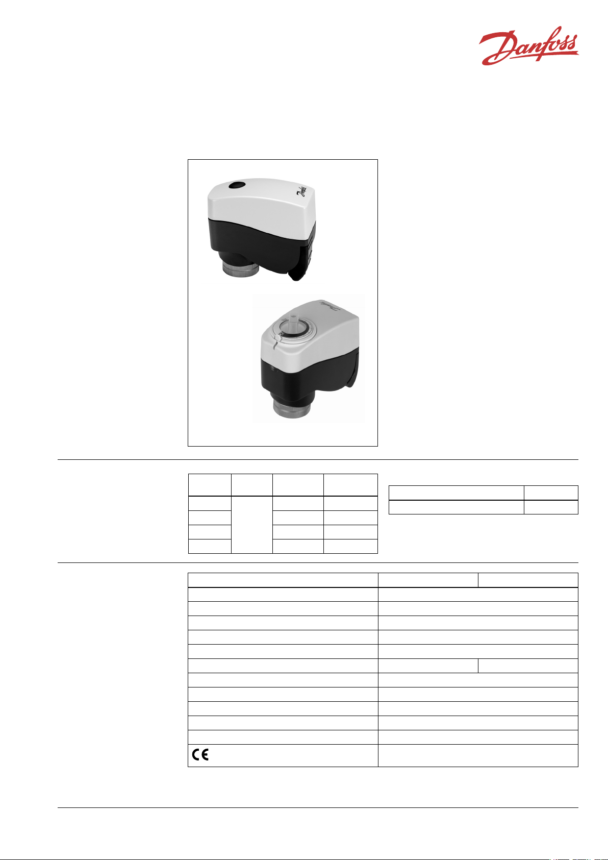
AME 01, AME 02
AME 01, AME 02, AME-H 01 and AME-H 02
actuators are used with VZ, VZL, VRBZ or with
AB-QM valves (AME version only). The actuator
can be used with fan coil units, induction units,
small reheaters, recoolers, and zone applications
in which hot/cold water is the controlled
medium.
Main data:
• Proportional version
• The advanced design incorporates no-force
switch-off at stem up position, which enables
use of the actuator on valves with different
nominal strokes and improves the controller
response.
• Force switch-off at stem down position
prevents overload of actuator and valve.
• No tools required for mounting
• Maintenance free during the lifetime
• Low noise operation
• Exercise cycle
• Supplied with 1.5 m cable.
AME-H 01, AME-H 02
Ordering
Technical data
Type
AME 01
AME 02 12 s/mm 082H8006
AME-H 01 24 s/mm 082H8023
AME-H 02 12 s/mm 082H8026
Type AME 01, AME-H 01 AME 02, AME-H 02
Power supply 24 Vac; +10 to –15%
Power consumption 3 VA
Frequency 50 Hz/60 Hz
Close of force 200 N
Max. stroke 5.5 mm
Speed 24 s/mm 12 s/mm
Max. medium temperature inside the pipe 120 °C
Ambient temperature 0 to 55 °C
Storage and transport temperature –40 to +70 °C
Protection code IP 42
Weight 0.34 kg
Supply
voltage
24 V~
- marking in accordance with standards
Speed Code No.
24 s/mm 082H8003
Spare parts
Type Code No.
1.5 m cable for AME, AME-H - 24 V 082H8009
EMC- Directive 89/336/EEC, 92/31/EEC, 93/68/EEC,
EN 50081-1 and EN 50082-1
SIBC VD.JC.N2.02 © Danfoss 08/05 1
Page 2
Data sheet Actuators for modulating control AME 01, AME-H 01, AME 02, AME-H 02
Installation
Disposal The actuator must be dismantled and the
elements sorted into various material groups
before disposal.
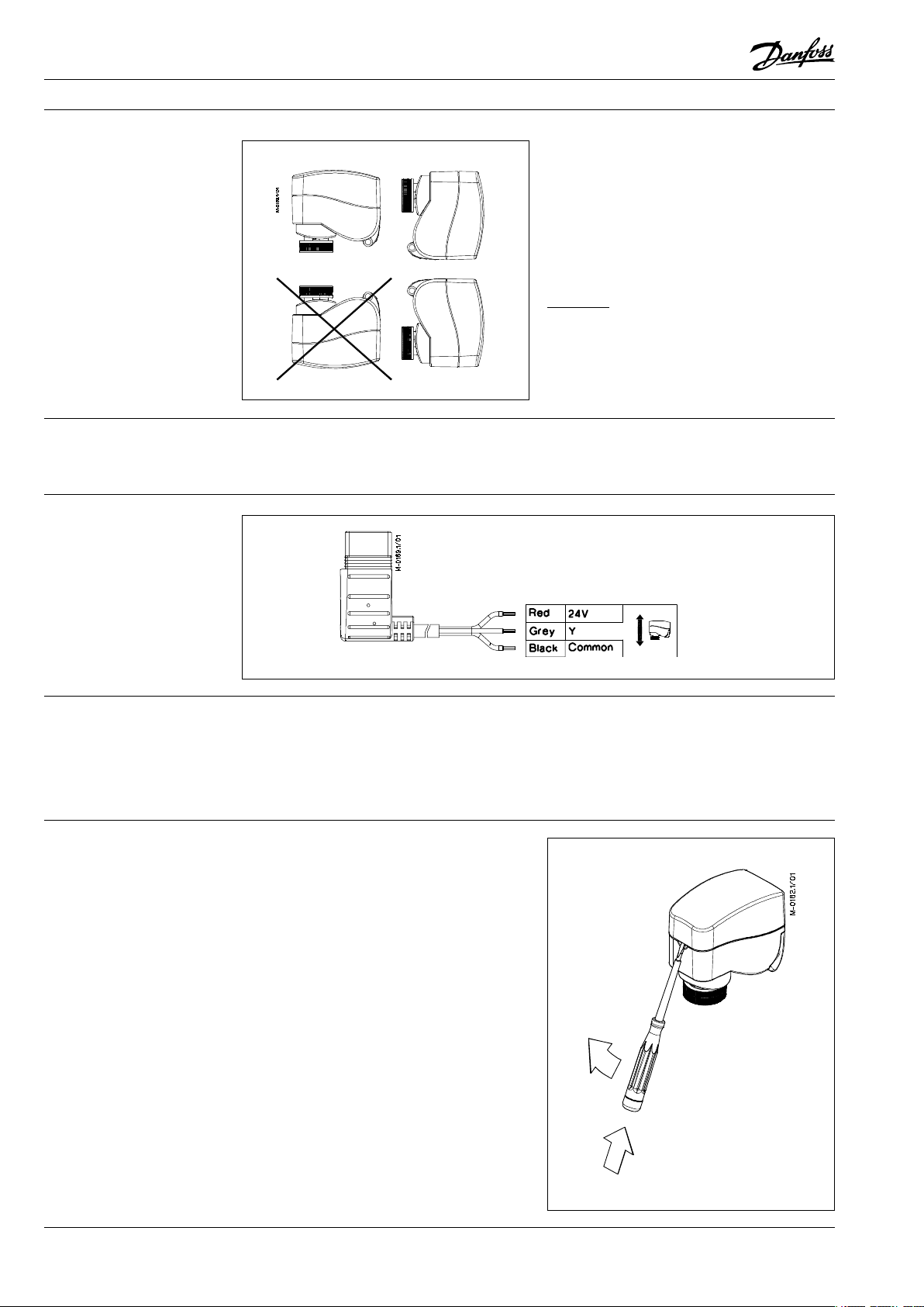
Wiring
Mechanical
The actuator should be mounted with the valve
stem in either horizontal position or pointing
upwards.
The actuator is fixed to the valve body by means
of a mounting ring which requires no tools for
mounting. The ring should be tightened by hand.
Electrical
Important: It is strongly recommended that the
mechanical installation is completed before the
electrical installation.
Each actuator is supplied with the connecting
cable for the controller.
Commissioning
Installation procedure
All actuators are factory tested prior to shipment.
The factory setting of the spindle is the fully
stem up position because of easier mechanical
connection of actuator on valve.
1 Check the valve seat. Ensure that the actuator
is mounted securely on valve body. Before
applying power to the actuator, check for
mechanical obstructions.
2 Ensure that the actuator is electrically isolated.
Remove the cover to set DIP switches (if
required only). See DIP switch settings (page
3) for details. Replace the cover and than
energize the actuator (24 Vac).
3 The load sensitive mechanism requires a
resistance, which is supplied by the valve,
therefore power should not be applied prior
to mounting on the valve. When power is
first applied the actuator begins with the
self-commissioning cycle. At first the actuator
will make a clicking sound. This is normal
and indicates that the actuator's no load
sensor is working properly. After a couple
of seconds this sound will cease. The whole
commisioning cycle will last approximately
6 min (AME 01, AME-H 01) or 3 min (AME 02,
AME-H 02).
Important: Uninstalled actuator will operate
properly only in stem down direction!
If uninstalled actuator is tested than use the Allen
key size 4 mm (or knob for AME-H version) in
order to drive actuator on it's top position.
2 VD.JC.N2.02 © Danfoss 08/05 SIBC
Page 3

Data sheet Actuators for modulating control AME 01, AME-H 01, AME 02, AME-H 02
DIP Switch Setting • SW5: Exercise cycle: If set to ON position,
The actuator has a function selection DIP switch
under the removable cover. In particular, if SW5 is
set to ON, the actuator will perform an automatic
stroke calibration cycle at power on and every
24 hours. The switch provides the following
the actuator performs one complete exercise
cycle every 24 hours to clear possible
accumulation of impurities from the valve
plug and seat and recalibrate the stroke.
functions:
• SW1: U/I - Input signal type selector: If set to
OFF position, voltage input is selected. If set
to ON position, current input is selected.
• SW2: 0/2 - Input signal range selector: If
set to OFF position, the input signal is in the
range from 0 V to 10 V (voltage input) or from
0 mA to 20 mA (current input). If set to ON
position, the input signal is in the range from
2 V to 10 V (voltage input) or from 4 mA to 20
mA (current input).
• SW3: D/I - Direct or inverse acting selector:
If set to OFF position, the actuator is direct
acting (stem lowers as voltage increases).
If set to ON position the actuator is inverse
acting (stem raises as voltage increases).
• SW4: Reset: Changing this switch position
will cause the actuator to go through a self
stroking cycle.
Manual override AME 01, AME 02
1 Remove the small soft plug from the lid.
2 Insert the Allen key size 4 mm into the
opening.
Caution:
Do not manually operate the
drive under the power!
3 Operate the drive manually in the desired
direction.
4 Pull out the key and insert the small soft plug
back.
If manual override has been used than Y signal
is not correct until the actuator reaches it's
end position. If this is not accepted reset the
actuator.
stem up
stem down
SIBC VD.JC.N2.02 © Danfoss 08/05 3
Page 4

Data sheet Actuators for modulating control AME 01, AME-H 01, AME 02, AME-H 02
a b
c
cable
release
slot
mounting
ring
M-diskon/01
Manual override
AME-H 01, AME-H 02
The position indicator is factory calibrated, but if
you need to make incication more precise or have
moved the knob while the actuator is removed
from the valve, then the following advice applies:
1 Energize the actuator with a signal to drive the
stem up (with the actuator fitted to the valve).
2 When it stops, rotate the position indicator
ring while pressing the setting lever , to
the position where the orienting groove
points to the minus sign (-). The knob
should not be turned in this case.
3 Energize the actuator with a signal to drive the
stem down.
Knob
Position indicator ring
Minus sign
Orienting groove
Setting lever
Disconnecting the cable
from the actuator
To disconnect the cable, first ensure that
the actuator is electrically isolated. Insert a
screwdriver into the cable release slot, push the
handle away from the mounting ring, and pull
the connector out of the actuator by hand.
4 VD.JC.N2.02 © Danfoss 08/05 SIBC
Page 5

88
49
83
76
77
M-dimenzije/01
Data sheet Actuators for modulating control AME 01, AME-H 01, AME 02, AME-H 02
Dimensions
AME 01, AME 02
AME-H 01, AME-H 02
Actuator - valve combinations
AME (-H) 01 / 02 +
VZ 2, VZL 2
AME(-H) 01 / 02 +
VZ 3, VZL 3
AME(-H) / 02 +
VZ 4, VZL 4
AME(-H) 01 / 02 +
VRBZ 2/3
AME 01 / 02 +
AB-QM
5 VD.JC.N2.02 © Danfoss 08/05 SIBC
Page 6

Data sheet Actuators for modulating control AME 01, AME-H 01, AME 02, AME-H 02
6 VD.JC.N2.02 © Danfoss 08/05 SIBC
 Loading...