

Page 1
Data Sheet
Electric Expansion Valve
Type AKVO 10
Valve designed for refrigeration plant
AKVO 10 is an electrically operated expansion
valve designed for refrigeration plant.
AKVO 10 has an internal lter.
The AKVO 10 range covers a capacity range
from 0.6 – 13.5 kW (R404A/R507) and is divided
in 7 capacities.
Features
Features
• Refrigerants: R744, R22/R407C, R404A/R507,
R410A, R134a, R407A, R23, R407F, R422B,
R422D, R448A, R449A, R449B, R450A, R452A,
R513A.
• The valve requires no adjustment
• Wide regulation range 10 – 100% of the full
capacity
• Internal lter
• Both expansion valve and solenoid valve
• Wide range for coils DC and AC
For a complete list of approved refrigerants,
visit www.products.danfoss.com and search for
individual code numbers, where refrigerants
are listed as part of technical data
AI236986442651en-000801
Page 2
Electric Expansion Valve, Type AKVO 10
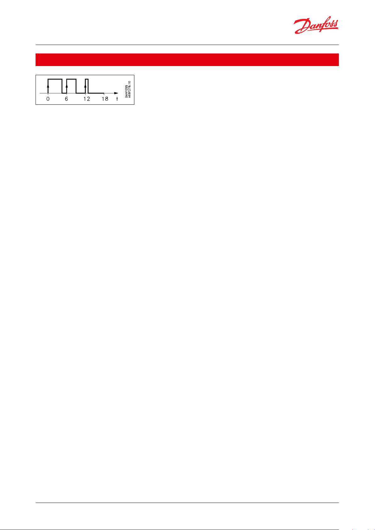
Functions
The valve capacity is regulated by means of pulse-width modulation. Within a period of six seconds a voltage signal
from the controller will be transmitted to and removed from the valve coil. This makes the valve open and close for
the ow of refrigerant.
The relation between this opening and closing time indicates the actual capacity. If there is an intense need for
refrigeration, the valve will remain open for almost all six seconds of the period. If the required amount of refrigerant
is modest, the valve will stay open during a fraction of the periode. The amount of refrigeration needed is
determined by the controller. When no refrigeration is required, the valve will remain closed and thus function as a
solenoid valve.
© Danfoss | Climate Solutions | 2021.05 AI236986442651en-000801 | 2
Page 3
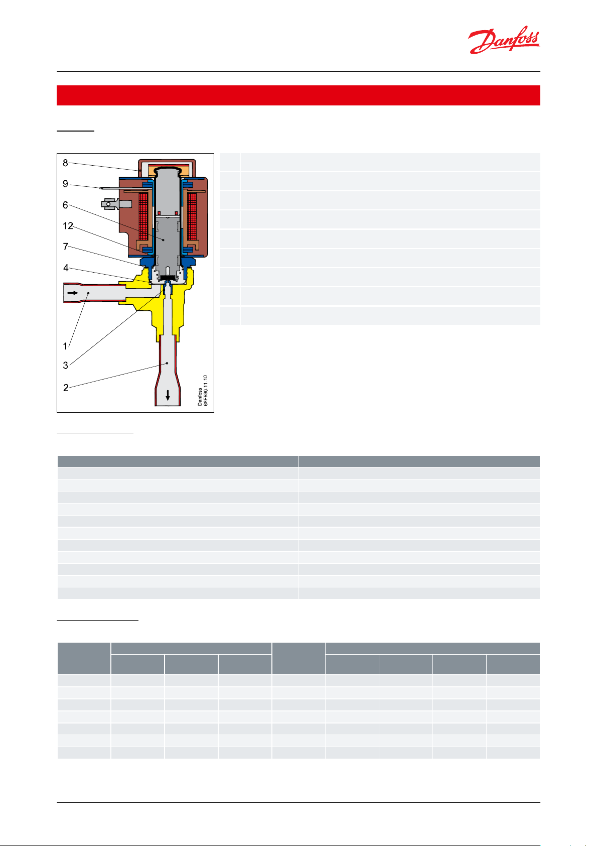
1234678912
Inlet
Outlet
Orice
Filter
Armature
Coated Copper gasket
Coil
DIN spades
O-ring
Description
Value
Tolerance of coil voltage
10 / - 15%
Enclosure to IEC 529
Max. IP67
Working principle
Pulse Width Modulation (PWM)
Recommended period of time
6 s.
Regulation range
10 – 100%
Connection
Solder
Evaporating temperature
-50 – 60 °C
Ambient temperature
-50 – 50 °C
Maximum Operation Pressure
Dierential (MOPD)
18 bar
Filter internal
MESH 60
Max. working pressure
28 barg
Valve type
Rated capacity kW
(1)
kv value [m3/h]
Connections Solder ODF
R22/ R407C
R134a
R404A/ R507
Inlet × outlet
[in.]
Code no.
Inlet × outlet
[in.]
Code no.
AKVO 10-1
1.0
0.9
0.8
0.010
3
⁄8
×
1
⁄2
068F4011
10 × 12
068F4012
AKVO 10-2
1.6
1.4
1.3
0.017
3
⁄8
×
1
⁄2
068F4013
10 × 12
068F4014
AKVO 10-3
2.6
2.1
2.0
0.025
3
⁄8
×
1
⁄2
068F4015
10 × 12
068F4016
AKVO 10-4
4.1
3.4
3.1
0.046
3
⁄8
×
1
⁄2
068F4017
10 × 12
068F4018
AKVO 10-5
6.4
5.3
4.9
0.064
3
⁄8
×
1
⁄2
068F4019
10 × 12
068F4020
AKVO 10-6
10.2
8.5
7.8
0.114
3
⁄8
×
1
⁄2
068F4021
10 × 12
068F4022
AKVO 10-7
16.3
13.5
12.5
0.209
1
⁄2
×
5
⁄8
068F4023
12 × 16
068F4024
Electric Expansion Valve, Type AKVO 10
Product specication
Design
Figure 1: Type AKVO 10
Technical data
Table 1: Type AKVO 10
Capacity tables
Table 2: Rated capacity and ordering
(1)
(1)
Rated capacities are based on: Condensing temperature t
Rated capacities are based on: Condensing temperature t
© Danfoss | Climate Solutions | 2021.05 AI236986442651en-000801 | 3
=32 °C. Liquid temperature tl=28 °C. Evaporating temperature te=5 °C
=32 °C. Liquid temperature tl=28 °C. Evaporating temperature te=5 °C
c
c
Page 4

∆p
valvepcpeΔp1Δp3Δp4
pressure drop across the valve
condensing pressure
evaporating pressure
pressure drop across the liquid line
pressure drop across the distributor system
pressure drop across the evaporator
Electric Expansion Valve, Type AKVO 10
NOTE:
Code numbers on request. AKVO 10 is supplied as an industrial pack (16 pieces).
Spare parts
AKVO is a non serviceable valve.
Valve sizing
To obtain an expansion valve that will function correctly under dierent load conditions it is necessary to consider
the following points when sizing the valve:
These points must be dealt with in the following sequence:
1.
Evaporator capacity
2.
Pressure drop across the valve
3.
Correction for subcooling
4.
Correction for evaporating temperature
5.
Determination of valve size
6.
Correctly dimensioned liquid line
1. Evaporator capacity
The evaporator capacity is found in the specications from the evaporator supplier
2. Pressure drop across the valve
The pressure drop across the valve directly determines the capacity and must therefore be considered. The pressure
drop across the valve is normally calculated as the condensing pressure less the evaporating pressure and sundry
other pressure drops in the liquid line, distributor, evaporator, etc. It is indicated in the following formula: Δp
- (pe + Δp1 + Δp3 + Δp4)
valve
= p
c
Figure 2: Pressure drop across the valve
NOTE:
The pressure drop across the liquid line and the distributor system must be calculated on the basis of the valve’s
max. capacity, as the valve operates with pulse-width modulation
Example:
Calculation of pressure drop across a valve:
Refrigerant: R22/R407C
Condensing temperature: 35 °C (pc = 13.5 bar)
Evaporating temperature: 0 – 6 °C (pe = 4.1 bar)
Δp1 = 0.2 bar
Δp3 = 0.8 bar
Δp4 = 0.1 bar
This will give the following equation:
Δp
= pc - (pe + Δp1 + Δp3 + Δp4)
valve
= 13.5 - (4.1 + 0.2 + 0.8 + 0.1)
= 8.3 bar
The found value for “pressure drop across the valve” is used later in the section “Determination of valve size”.
© Danfoss | Climate Solutions | 2021.05 AI236986442651en-000801 | 4
Page 5

Correction
factor
4 K
10 K
15 K
20 K
25 K
30 K
35 K
40 K
45 K
50 K
R22/R407C
1.00
0.94
0.90
0.87
0.83
0.80
0.77
0.74
0.72
0.69
R134a
1.00
0.93
0.88
0.84
0.80
0.76
0.73
0.70
0.68
0.65
R404A/R507
1.00
0.91
0.83
0.78
0.73
0.68
0.65
0.61
0.59
0.56
Evaporating tem‐
perature te [°C]
50-10
-15
-20
-30
-40
AKVO 10
1.25
1.25
1.25
1.25
1.6
1.6
1.6
Electric Expansion Valve, Type AKVO 10
3. Correction for subcooling
The evaporator capacity used must be corrected, if the subcooling deviates from 4 K. Use the actual correction
factor indicated in the table. Multiply the evaporator capacity by the correction factor to obtain the corrected
capacity.
Table 3: Correction factors for subcooling Δt
sub
Corrected capacity = evaporator capacity x correction factor. The corrected capacity is used in the section
“Determination of valve size”.
Example of corection:
Refrigerant: R22/R407C
Evaporator capacity Qe: 5 kW
Subcooling: 10 K
Correction factor according to the table = 0.94
Corrected capacity = 5 × 0.94 = 4.7 kW.
NOTE:
Too little subcooling may cause ash gas.
4. Correction for evaporating temperature (te)
To obtain a correctly dimensioned valve it is important that the application is considered.
Depending on the application, the valve should have an overcapacity enabling it to cope with the extra amount of
refrigeration needed during certain periods, e.g. during the defrost recovery process.
The valve’s opening degree should therefore be between 50 and 75% when regulating. In this way it is ensured that
the valve has a suciently wide regulation range, so that it can manage changed loads at or near the normal
working point. Correction factors based on the evaporating temperature are indicated below:
Table 4: Correction factors for evaporating temperature (te)
5. Determination of valve size
When the valve size meeting the required capacity is selected it is important to note that the capacity indications
are the valve’s rated capacity, i.e. when the valve is 100% open.
In this section we tell you how the valve’s size is determined.
There are three factors that have an inuence on the choice of the valve:
• The pressure drop across the valve
• The corrected capacity (correction for subcooling)
• The corrected capacity for evaporating temperature
The three factors have been described earlier in this section on dimensioning.
When these three factors have been established, the selection of the valve can be made:
• First multiply the “corrected capacity” by a value stated in the table.
• Use the new value in the capacity table in combination with the pressure drop value.
• Now select the valve size.
Example of selection of valve
Use as starting point the two earlier mentioned examples, where the following two values have been obtained:
Δp
= 8.3 bar
valve
© Danfoss | Climate Solutions | 2021.05 AI236986442651en-000801 | 5
Page 6

Electric Expansion Valve, Type AKVO 10
Qe corrected = 4.7 kW
The valve should be used in a coldroom. Consequently, 1.25 should be selected as “correction factor for the
evaporating temperature”.
The dimensioned capacity will then be:
1.25 x 4.7 kW = 5.88 kW.
Now select a valve size from one of the capacity tables.
With the given values Δp
= 8.3 bar
valve
and a capacity of 5.88 kW, select the valve size for AKV 10-5.
This valve will have a capacity of approx. 7 kW.
6. Correctly dimensioned liquid line
To obtain a correct supply of liquid to the AKVO valve, the liquid line to the individual AKVO valve must be correctly
dimensioned. The liquid ow rate should not exceed 1 m/sec. This must be observed on account of the pressure
drop in the liquid line (lack of subcooling) and pulsations in the liquid line.
Dimensioning of the liquid line must be based on the capacity of the valve at the pressure drop with which it is
operating (cf. capacity table), and not on the evaporator capacity.
© Danfoss | Climate Solutions | 2021.05 AI236986442651en-000801 | 6
Page 7

Danfoss
68F497.11.FW
Inlet
Outlet
Electric Expansion Valve, Type AKVO 10
Dimensions and weight
Figure 3: Net weight without coil:
0.38 kg
A: 64 mm / 2.52 in.
B: 64 mm / 2.52 in.
C: 141 mm / 5.55 in.
© Danfoss | Climate Solutions | 2021.05 AI236986442651en-000801 | 7
Page 8

Voltage [V]
Frequency
[Hz]
Code no.
AKVO 10-1 to
AKVO 10-5
AKVO 10-6
AKVO 10-7
Power con‐
sumption
With 1 m 3
core cable
[IP67]
With terminal
box [IP67]
With DIN
plugs and
protective
cap [IP20]
2450018F6257
018F6707
018F6182√÷
÷
Holding:
10 W
21 VA
In rush:
44 VA
11550—
018F6711—√√÷
11560018F6260
018F6710
018F6185√√÷23050—
018F6701—√√÷
23060——018F6189√√÷24050018F6252
018F6702
018F6177√√÷24060—
018F6713—√√÷
230
50/60
018F6282
018F6732—√√÷
Voltage [V]
Frequency [Hz]
With terminal box
[IP67]
AKVO 10-1 to AKVO
10-5
AKVO 10-6
AKVO 10-7
Power consumption
2450018F6807√÷
÷
Holding:
20 W
45 VA
In rush:
60 VA
2460018F6815√÷÷110
50
018F6811√√÷110
60
018F6813√√÷230
50
018F6801√√÷230
60
018F6814√√÷240
50
018F6802√√
√
Voltage [V]
Frequency [Hz]
With terminal box
[IP67]
AKVO 10-1 to AKVO
10-5
AKVO 10-6
AKVO 10-7
Power consumption
2450018F6904√√
√
Holding:
20 W
45 VA
In rush:
60 VA
2460018F6902√√
√
230
50
018F6905√√
√
Voltage [V]
With terminal box [IP67]
AKVO 10-1 to AKVO
10-5
AKVO 10-6
AKVO 10-7
Power consumption
220
018F6851√√√20 W
230
018F6781√√√18 W
Electric Expansion Valve, Type AKVO 10
Ordering
Table 5: 10 W alternating current AC
Table 6: 12 W alternating current AC
Table 7: 20 W alternating current AC
Table 8: 18 W and 20 W direct current DC
© Danfoss | Climate Solutions | 2021.05 AI236986442651en-000801 | 8
Page 9

Document name
Document type
Document topic
Approval authority
UL MH7648
Electrical - Safety Certicate
-
UL
Electric Expansion Valve, Type AKVO 10
Certicates, declarations and approvals
The list contains all certicates, declarations, and approvals for this product type. Individual code number may have
some or all of these approvals, and certain local approvals may not appear on the list.
Some approvals may change over time. You can check the most current status at danfoss.com or contact your local
Danfoss representative if you have any questions.
Table 9: Certicates, declarations and approvals
© Danfoss | Climate Solutions | 2021.05 AI236986442651en-000801 | 9
Page 10

Online support
Danfoss oers a wide range of support along with our products, including digital product information, software,
mobile apps, and expert guidance. See the possibilities below.
The Danfoss Product Store
The Danfoss Product Store is your one-stop shop for everything product related—no matter where
you are in the world or what area of the cooling industry you work in. Get quick access to essential
information like product specs, code numbers, technical documentation, certications, accessories,
and more.
Start browsing at store.danfoss.com.
Find technical documentation
Find the technical documentation you need to get your project up and running. Get direct access to
our ocial collection of data sheets, certicates and declarations, manuals and guides, 3D models
and drawings, case stories, brochures, and much more.
Start searching now at www.danfoss.com/en/service-and-support/documentation.
Danfoss Learning
Danfoss Learning is a free online learning platform. It features courses and materials specically
designed to help engineers, installers, service technicians, and wholesalers better understand the
products, applications, industry topics, and trends that will help you do your job better.
Create your Danfoss Learning account for free at www.danfoss.com/en/service-and-support/learning.
Get local information and support
Local Danfoss websites are the main sources for help and information about our company and
products. Find product availability, get the latest regional news, or connect with a nearby expert—all
in your own language.
Find your local Danfoss website here: www.danfoss.com/en/choose-region.
Coolselector®2 - nd the best components for you HVAC/R system
Coolselector®2 makes it easy for engineers, consultants, and designers to nd and order the best
components for refrigeration and air conditioning systems. Run calculations based on your operating
conditions and then choose the best setup for your system design.
Download Coolselector®2 for free at coolselector.danfoss.com.
Any information, including, but not limited to information on selection of product, its application or use, product design, weight, dimensions, capacity or any other
technical data in product manuals, catalogues descriptions, advertisements, etc. and whether made available in writing, orally, electronically, online or via download,
shall be considered informative, and is only binding if and to the extent, explicit reference is made in a quotation or order conrmation. Danfoss cannot accept any
responsibility for possible errors in catalogues, brochures, videos and other material. Danfoss reserves the right to alter its products without notice. This also applies to
products ordered but not delivered provided that such alterations can be made without changes to form, t or function of the product. All trademarks in this material
are property of Danfoss A/S or Danfoss group companies. Danfoss and the Danfoss logo are trademarks of Danfoss A/S. All rights reserved.
© Danfoss | Climate Solutions | 2021.05 AI236986442651en-000801 | 10
 Loading...