

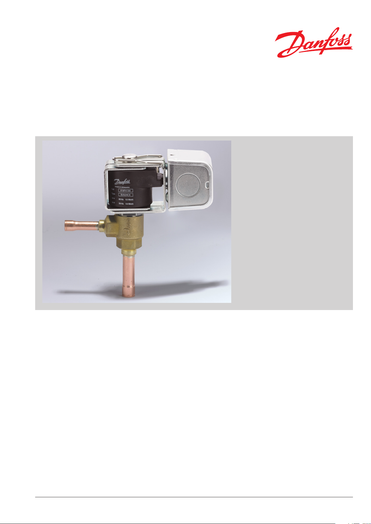
Data sheet
Electric expansion valve for R744 (CO2)
Type AKVH
AKVH are electrically operated expansion
valves designed for refrigerating plants using
R744 refrigerant.
The AKVH valves are normally controlled by a
controller from Danfoss’ range of
ADAP- KOOL® controllers.
The AKVH valves are supplied as a component
program, as follows:
• Separate valve.
• Separate coil with junction box or conduit
hub.
• Spare parts in the form upper part, orice
and lter.
The orice assembly is replaceable.
The AKVH 10 valves cover a capacity range
from 0.1 TR to 3 TR in refrigeration applications
and 0.2 TR to 6.25 TR in freezing applications.
Features
y For R744 refrigerant.
y The valve requires no adjustment.
y Wide regulation range.
y Replaceable orice assembly.
y Normally closed, solenoid tight expansion
valve.
y Wide range of a.c. coils.
y Enables energy saving minimum stable
superheat and adaptive defrost algorithms.
y Provides excellent distribution and oil return
due to turbulent ow.
DKRCC.PD.VA1.D4.22 / 520H9079
Data sheet Electric expansion valves type AKVH for R744 (CO2)
Approvals
Technical data
PED (97/23/EC A3.P3)
(Refrigerant valve) 53RO
The Low Voltage Directive 73/23/EC
with amendments EN 60730-2-8
Valve type AKVH 10
Working principle (Pulse-width modulation) PWM
Recommended period of time 6 Seconds
Capacity (R744)
Regulation range (Capacity range) 10 – 100%
Connection Solder
Evaporating temperature - 76 – 140 °F
Ambient temperature - 58 – 122 °F
Leak of valve seat <0.02% of Cv-value
MOPD 435 psi (30 bar)
Filter, replaceable Internal 100 μm
Max. working pressure 1305 psig / 90 barg
1
) 1305 psig / 90 barg under stand still conditions, but under normal
operating conditions, there must be liquid to the inlet
of the valve.
Refrigeration: 0.1 TR – 3 TR
Freezing: 0.2 TR – 6.25 TR
1)
The individual capacities are indicated with a number forming part of the type designation.
The number represents the size of the orice of the valve in question. A valve with orice 3 will for
example be designated AKVH 10-3.
2 DKRCC.PD.VA1.D4.22 / 520H9079 © Danfoss A/S (AC-MCI / sw), 2015-02

Data sheet Electric expansion valves type AKVH for R744 (CO2)
Rated capacity and ordering
AKVH 10 R744
C
Valve type /
orifice no.
AKVH 10-0 0.1 0.2 0.132
AKVH 10-0 0.1 0.2 0.132 – 10 × 12 mm 068F4088
AKVH 10-1 0.3 0.6 0.044
AKVH 10-1 0.3 0.6 0.044 – 10 × 12 mm 068F4089
AKVH 10-2 0.5 1.0 0.074
AKVH 10-2 0.5 1.0 0.074 – 10 × 12 mm 068F4090
AKVH 10-3 0.7 1.5 0.110
AKVH 10-3 0.7 1.5 0.110 – 10 × 12 mm 068F4091
AKVH 10-4 1.2 2.5 0.202
AKVH 10-4 1.2 2.5 0.202 – 10 × 12 mm 068F4092
AKVH 10-5 1.9 3.8 0.282
AKVH 10-5 1.9 3.8 0.282 – 10 × 12 mm 068F4093
AKVH 10-6 3.0 6.1 0.502
AKVH 10-6 3.0 6.1 0.502 – 10 × 12 mm 068F4094
Rated capacity TR
Refrigeration Freezing gal/min
v
value
Connection size
Solder ODF/ODF
[in.]
3/8 × 1/2 in.
3/8 × 1/2 in.
3/8 × 1/2 in.
3/8 × 1/2 in.
3/8 × 1/2 in.
3/8 × 1/2 in.
3/8 × 1/2 in.
Single pack
[mm]
– 068F4078
– 068F4079
– 068F4080
– 068F4081
– 068F4082
– 068F4083
– 068F4084
1 valve each
AKVH 10 R744
C
Valve type /
orifice no.
AKVH 10-0 0.1 0.2 0.132
AKVH 10-0 0.1 0.2 0.132 – 10 × 12 mm 068F4058
AKVH 10-1 0.3 0.6 0.044
AKVH 10-1 0.3 0.6 0.044 – 10 × 12 mm 068F4059
AKVH 10-2 0.5 1.0 0.074
AKVH 10-2 0.5 1.0 0.074 – 10 × 12 mm 068F4060
AKVH 10-3 0.7 1.5 0.110
AKVH 10-3 0.7 1.5 0.110 – 10 × 12 mm 068F4061
AKVH 10-4 1.2 2.5 0.202
AKVH 10-4 1.2 2.5 0.202 – 10 × 12 mm 068F4062
AKVH 10-5 1.9 3.8 0.282
AKVH 10-5 1.9 3.8 0.282 – 10 × 12 mm 068F4063
AKVH 10-6 3.0 6.1 0.502
AKVH 10-6 3.0 6.1 0.502 – 10 × 12 mm 068F4064
Rated capacity TR
Refrigeration Freezing gal/min
v
value
Connection size
Solder ODF/ODF
[in.]
3/8 × 1/2 in.
3/8 × 1/2 in.
3/8 × 1/2 in.
3/8 × 1/2 in.
3/8 × 1/2 in.
3/8 × 1/2 in.
3/8 × 1/2 in.
Industrial pack
[mm]
– 068F4068
– 068F4069
– 068F4070
– 068F4071
– 068F4072
– 068F4073
– 068F4074
32 valves each
Spare parts
© Danfoss A/S (AC-MCI / sw), 2015-02 DKRCC.PD.VA1.D4.22 / 520H9079 3
Orifice no. Contents Code no.
0
1
2
3
4
6
4 pc. orifice
4 pc. gasket
3 pc. orifice
3 pc. gasket
068F5283
068F52845

Data sheet Electric expansion valves type AKVH for R744 (CO2)
Technical data
Ordering
Design
In accordance with UL 429
Power supply
Alternating current (a.c.)
Permissible voltage variation
Alternating current (a.c.):
50 Hz and 60 Hz: -10% – 15%
50/60 Hz: +/- 10%
Power consumption
Alternating current (a.c.): Inrush: 49 VA;
Holding: 28 VA, 16 W
BJ and BX Coils
Valve type Coil type
Junction box NEMA 2
AKVH / EVRH
Conduit boss NEMA 4
AKVH / EVRH
BJ120BS 7 18 120 60 16 018F4130
BJ208BS 7 18 208 60 16 018F4132
BJ240BS 7 18 240 60 16 018F4134
BX120BS 98 250 120 60 16 018F4131
BX208BS 98 250 208 60 16 018F4133
BX240BS 98 250 240 60 16 018F4135
Wire length
[in.] [cm]
Insulation of coil wire
Class H according to IEC 85
Connection
Junction box or Conduit boss
Enclosure, IEC 60529
Junction box NEMA 2 ~ IP 12–32
Conduit boss NEMA 4 ~ IP 54
Ambient temperature
-40 °F – 122 °F / -40 °C – 50 °C
Voltage
[V a.c.]
Frequency
[Hz]
consumption
Power
Code no.
[W]
4 DKRCC.PD.VA1.D4.22 / 520H9079 © Danfoss A/S (AC-MCI / sw), 2015-02

Data sheet Electric expansion valves type AKVH for R744 (CO2)
Capacity
Capacity in TR R744
Valve type
Pressure drop across valve ∆p psi 1)
29 58 87 116 145 174 203 232 261
AKVH 10-0 0.094 0.125 0.151 0.168 0.185 0.199 0.208 0.216 0.222
AKVH 10-1 0.256 0.341 0.427 0.455 0.512 0.540 0.569 0.597 0.597
AKVH 10-2 0.398 0.569 0.654 0.739 0.796 0.881 0.910 0.938 0.967
AKVH 10-3 0.626 0.881 1.052 1.166 1.251 1.365 1.422 1.479 1.535
AKVH 10-4 1.024 1.393 1.649 1.848 2.019 2.189 2.275 2.360 2.417
AKVH 10-5 1.592 2.189 2.616 2.900 3.156 3.412 3.583 3.696 3.839
AKVH 10-6 2.559 3.497 4.151 4.635 5.004 5.431 5.687 5.914 6.113
Valve type
Pressure drop across valve ∆p psi
290 319 348 377 406 435 464 493 507
AKVH 10-0 0.227 0.230 0.233 0.239 0.242 0.242 0.245 0.247 0.247
AKVH 10-1 0.626 0.626 0.654 0.654 0.654 0.682 0.682 0.682 0.682
AKVH 10-2 0.995 1.024 1.052 1.052 1.081 1.081 1.081 1.081 1.081
AKVH 10-3 1.564 1.592 1.621 1.649 1.678 1.678 1.706 1.706 1.706
AKVH 10-4 2.502 2.531 2.588 2.644 2.673 2.701 2.701 2.730 2.730
AKVH 10-5 3.924 4.009 4.095 4.151 4.208 4.237 4.265 4.265 4.265
AKVH 10-6 6.256 6.369 6.512 6.625 6.682 6.739 6.796 6.796 6.824
1
) Rated capacitities are based on
Subcooling t
Evaporating temperature te = -13F
Superheating t
= 7.2 F
sub
sup
= 9 F
Valve sizing using calculation software
It is strongly recommended to use Cool Selector to nd the correct valve for our application
The software can be downloaded from the Danfoss website. When using the calculation software it is
recommended to choose a valve that is between 50 and 75% loaded at the nominal capacity. In
addition, the liquid velocity in the line leading to the valve should not exeed 3ft/s (1m/s).
© Danfoss A/S (AC-MCI / sw), 2015-02 DKRCC.PD.VA1.D4.22 / 520H9079 5

Data sheet Electric expansion valves type AKVH for R744 (CO2)
Danfoss
R64-3005.10
Valve sizing
To obtain an expansion valve that will function
correctly under dierent load conditions it is
necessary to consider the following points when
sizing the valve.
These points must be dealt with in the following
sequence:
1) Evaporator capacity
The evaporator capacity is found in the
specications from the evaporator supplier.
2) Pressure drop across the valve
The pressure drop across the valve directly
determines the capacity and must therefore be
considered.
P
∆P
∆P
1
∆P
3
∆P
1) Evaporator capacity
2) Pressure drop across the valve
3) Correction for subcooling
4) Correction for evaporating temperature
5) Determination of valve size
6) Correctly dimensioned liquid line
The pressure drop across the valve is normally
calculated as the receiver pressure less the
evaporating pressure and sundry other pressure
drops in the liquid line, distributor, evaporator, etc.
It is indicated in the following formula:
∆p
= pc - (pe + ∆p1 + ∆p3 + ∆p4)
valve
4
P
∆p
pressure drop across the valve
valve
pc receiver pressure
pe evaporating pressure
∆p1 pressure drop across the liquid line
∆p3 pressure drop across the distributor system
∆p4 pressure drop across the evaporator
Note! The pressure drop across the liquid line and
the distributor system must be calculated on the
basis of the valve’s max. capacity, as the valve
operates with pulse-width modulation.
Example of calculation of pressure drop across a
valve:
Refrigerant: R744
p
= Receiver pressure: 580 psig (at 43
c
o
F)
Evaporating temperature: 23 oF (pe = 426 psig)
∆p1 = 2.9 psi
∆p3 = 12 psi
∆p4 = 1.5 psi
This will give you the following equation:
∆p
= pc - (pe + ∆p1 + ∆p3 + ∆p4)
valve
= 40 - (29.4 + 0.2 + 0.8 + 0.1)
= 580 - (426 + 2.9 + 12 + 1.45)
= 138 psi
The found value for “pressure drop across the
valve” is used later in the section “Determination
of valve size”.
6 DKRCC.PD.VA1.D4.22 / 520H9079 © Danfoss A/S (AC-MCI / sw), 2015-02

Data sheet Electric expansion valves type AKVH for R744 (CO2)
Valve sizing
3) Correction for subcooling
The evaporator capacity used must be
Multiply the evaporator capacity by the
correction factor to obtain the corrected capacity.
corrected, if the subcooling deviates from
-452.47 oF. Use the actual correction factor
indicated in the table.
Correction factors for subcooling ∆t
Correction factor [oF] 7.2 18 27 36 45 54 63 72 81 90
R744 1.00 0.91 0.86 0.81 0.77 0.73 0.69 0.66 0.63 0.60
Corrected capacity = evaporator capacity x correction factor.
The corrected capacity is used in the section
“Determination of valve size”.
Example of corection:
sub
Correction factor according to the table = 0.91
Corrected capacity = 1.42 x 0.91 = 1.29 TR.
Note: Too little subcooling may cause ash gas.
Refrigerant: R744
Evaporator capacity Qe: 1.42 TR
Subcooling: 18 oF
4) Correction for transient conditions and
evaporating temperature (te)
To obtain a correctly dimensioned valve it is
important that the application is considered.
Depending on the application, the valve
should have an overcapacity enabling it to
cope with the extra amount of refrigeration
needed during certain periods, e.g. during the
defrost recovery process.
The valve’s opening degree should therefore be
between 50 and 75% when regulating. In this
way it is ensured that the valve has a suciently
wide regulation range, so that it can manage
changed loads at or near the normal working
point.
The change in capacity as an eect of the
deviation in refrigerant density is included in this
correction factor.
Correction factor for transient conditions and
evaporating temperature (te)
Evaporating temperature te °F 50 to -58
AKVH 10 1.6
5) Determination of valve size
When the valve size meeting the required
capacity is selected it is important to note that
the capacity indications are the valve’s rated
capacity, i.e. when the valve is 100% open.
In this section we tell you how the valve’s size is
determined.
There are three factors that have an inuence
on the choice of the valve:
- the pressure drop across the valve
- the corrected evaporator
(correction for subcooling)
- the corrected capacity for evaporating
temperature
Example of selection of valve
Use as starting point the two earlier mentioned
examples, where the following two values have
been obtained:
∆p
= 138 psi
valve
Q
e corrected
= 1.29 TR
The valve should be used in a coldroom.
1.6 is the“correction factor for the evaporating
temperature”.
The three factors have been described earlier in
this section on dimensioning. When these
three factors have been established, the
selection of the valve can be made:
- First you multiply the “corrected capacity” by a
value stated in the table.
- Use the new value in the capacity table in
combination with the pressure drop value.
- Now select the valve size.
The dimensioned capacity will then be:
1.6 x 1.29 TR = 2.07 TR.
Now select a valve size from one of the capacity
tables.
With the given values ∆p
= 138 psi and a
valve
capacity of 2.07 TR, select the valve size for AKVH
10-5.
This valve has a capacity of approx. 2.90 TR
© Danfoss A/S (AC-MCI / sw), 2015-02 DKRCC.PD.VA1.D4.22 / 520H9079 7

Data sheet Electric expansion valves type AKVH for R744 (CO2)
ft./s
g/m
3.08
psi
Valve sizing 6) Correctly dimensioned liquid line
To obtain a correct supply of liquid to the AKVH
valve, the liquid line to the individual AKVH
valve must be correctly dimensioned.
The liquid ow rate should not exceed
3 ft/s
R 744
2.64
2.20
1.76
1.32
0.88
0.44
0
6
4.5 346073 145.0 218 290 363 435 508
Design and function
This must be observed on account of the
pressure drop in the liquid line (lack of
subcooling) and pulsations in the liquid line.
Dimensioning of the liquid line must be based on
the capacity of the valve at the pressure drop
with which it is operating (cf. capacity table), and
not on the evaporator’s capacity.
Danfoss
68Z8089.11
1. Inlet
2. Outlet
3. Orice
4. Filter
5. Valve seat
6. Armature
7. Copper gasket
8. Coil
The valve capacity is regulated by means of
pulse-width modulation. Within a period of six
seconds a voltage signal from the controller will
be transmitted to and removed from the valve
coil. This makes the valve open and close for the
ow of refrigerant.
The relation between this opening and closing time
indicates the actual capacity. If there is an intense
for almost all six seconds of the period. If the
required amount of refrigeration is modest, the
valve will only stay open during a fraction of the
period. The amount of refrigeration needed is
determined by the controller.
When no refrigeration is required, the valve will
remain closed and thus function as a solenoid
valve.
Danfoss
68F563.10
need for refrigeration, the valve will remain open
8 DKRCC.PD.VA1.D4.22 / 520H9079 © Danfoss A/S (AC-MCI / sw), 2015-02

Data sheet Electric expansion valves type AKVH for R744 (CO2)
67 mm
97 mm
48 mm
⁄
8 mm
Dimensions and weight
AKVH valve
Dimensions and
weight Coils
in.
Danfoss
68Z8088.11
⁄
in.
10 mm
75 mm
2 ⁄ in.
½ in.
12 mm
⁄ in.
10 mm
2
⁄
1 ⁄ in.
in.
⁄
3
Weight excluding coil
0.84lbs = 0.38 kg
in.
100mm (4 in.)
Danfoss
18F07.11
Junction box
Weight: 0.86 lbs / 0.39 kg
50mm (2 in.)
52mm (2 in.)
74mm (3 in.)
Danfoss
18F06.10
41mm (1
Conduit boss
Weight: 0.72 lbs / 0.33 kg
5
/8 in.)
48mm (2 in.)
9 DKRCC.PD.VA1.D4.22 / 520H9079 © Danfoss A/S (AC-MCI / sw), 2015-02
 Loading...