

Page 1
Fact Sheet
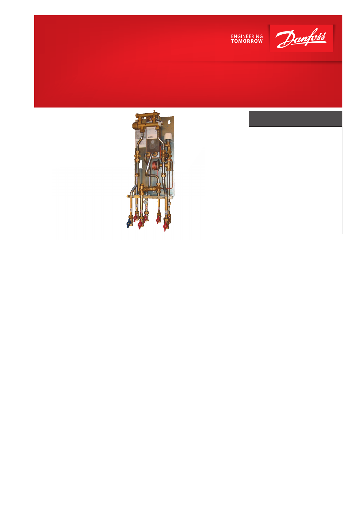
Akva Vita TDP Shaft
Direct flat station for mounting in shaft in a dwelling house
FEATURES AND BENEFITS
• Flat station for district heating
• Direct heating, DHW heating based
on the flow principle
• Capacity: 15 kW heating
35 kW domestic hot water
• Maximum hot-water comfort supply
• Minimum space required for installation
• Pipes and plate heat exchanger
made of stainless steel
• Minimized risk of lime scale and
bacteria formation
Application
The Akva Vita TDP Shaft is an instantaneous
water heater featuring high performance
and simple operation. The
Shaft is developed for flat systems supplied
from a scondary connected district
heating system, a block heating system
or a centrally located boiler system in a
dwelling house.
District heating (DH)
The flat station is prefabricated with
interconnecting components such as
differential pressure control, upright
positioned fitting piece for insertion of
a heat meter and DCW meter, sensor
pockets as well as strainer, thermometer
and ball valves.
Heating (HE)
The heating side is designed for direct
ge-neration of heat in a 2-pipe system.
The differential pressure control sets the
optimum operation conditions for radiator
thermostatic valves, in order to enable
individual temperature control in each
room. In order to enable a time-depending
temperature control program, a zone valve
with actuator and a room thermostat can
be included as an option..
Akva Vita TDP
Domestic hot water (DHW)
The domestic hot water is prepared in the
heat exchanger based on the flow principle.
Supreme ease of operation is obtained via
hydraulic regulation of the domestic hot
water through a proportional valve - the PM
controller, thereby guaranteeing a constant
domestic water temperature at all times. The
use of hydraulic regulation largely prevents
the formation of lime scale and bacteria, due
to the fact, that the valve closes immediately
when tapping ends and thereby the heat
exchanger is not constantly kept warm. A
thermostatic by-pass enables tapping of hot
water without any delay - ensuring the best
possible efficiency and economy.
The Akva Vita TDP Shaft is equipped with
by-pass function as standard, but it is also
prepared for DHW circulation. Switching
to DHW circulation is possible from a
constructional point of view, requiring no
extra components.
Mounting
Please note the application-specific
dimensions, which makes the Akva Vita
TDP Shaft especially suitable for mounting
in a technique shaft. Akva Vita TDP Shaft
can be mounted directly on the wall or it
can be mounted by use of the enclosed
wall brackets. Mounting with wall
brackets generates a distance of 100 mm
between flat station and wall for the piping
arrangements.
Construction
All pipes are made of stainless steel. The
connections are made by nuts and gaskets.
www.danfoss.com
Page 2
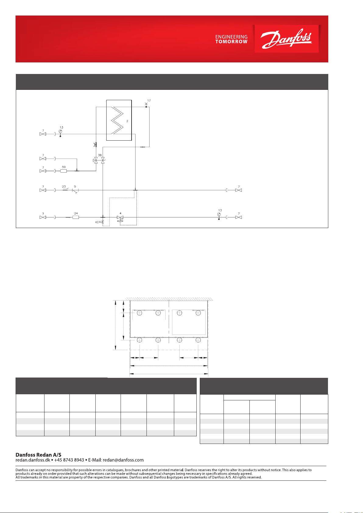
CIRCUIT DIAGRAM – EXAMPLE
DHW
DCW
DCW
2 Plate heat exchanger DHW
4 Differential pressure controller
5 Strainer
7 Ball valve
13 Thermometer
17 Air valve
23 Sensor pocket for heat meter ½”
24 Fitting piece for heat meter ¾” x 110 mm
38 PM controller
40 Danfoss FJVR for by-pass/circulation
59 Fitting piece for DCW meter ¾” x 110 mm
DH
Supply
DH
Return
Technical parameters:
Nominal pressure: PN 10
DH supply temperature: T
DCW static pressure: p
Chloride compounds: Max. 300 mg/l
Weight incl. cover: 20,0 kg
(incl. packing)
Dimensions (mm):
= 100 °C
max
= 2,5 bar
min
H715 x W295 x D185
Pipes dimensions (mm):
Primary: Dia. 18
Secundary: Dia. 18
Connections sizes:
DH + DCW + DHW: G ¾” (IT)
HE + optional circ.: G ¾” (IT)
(By-pass)
Connections:
A Domestic cold water (DCW) outlet
B Domestic hot water (DHW)
C Heating (HE) supply
D Heating (HE) return
E Domestic cold water (DCW) inlet
F District heating (DH) supply
G Circulation
H District heating (DH) return
Top view
C D
G H
290
295
185
46
102
A
E F
B
70 70
HE
Supply
HE
Return
Options:
• Ball valve G ¾” (ext. thread)
• Ball valve with pocket for pressure for
pressure/thermometer gauge G ¾” (ext.
thread)
• Ball valve with pocket for pressure for
pressure/thermometer gauge G ¾” (int.
thread)
• Thermometer Ø35 mm
• Connection pipe for circulation
• Zone valve VMT 15/8 with TWA-V/230
V AC
• Room thermostat TP 7000
• Room thermostat TP 7000RF incl. RX-1
• Mounting of heat meter (supplied by
customer)
* requires local approval
3535
DHW: CAPACITY EXAMPLES AT 10°C / 45°C
DHW
Capacity
[kW]
32,3 U141RH 55 22 13,16 0,23 840
32,3 U141RH 60 18 13,16 0,16 660
41,0 U141RH 60 20 16,86 0,24 880
53,0 U141RH 60 22 21,84 0,45 1200
*) Stated pressure loss values are complete, incl. pipes. heat exchanger and valves
Plate heat
exchanger
© Danfoss | DHS-SRMT/ PL | 2018. 04
Supply flow
primary
[°C]
Return flow
primary
[°C]
DHW tap
load
[l/min]
Pressure loss
primary*
[bar]
Flow rate
primary
[l/h]
HEATING: CAPACITY EXAMPLES
Heating
Capacity
kW
10 20 20 0,30 428
10 30 30 0,26 284
10 40 40 0,24 216
15 20 20 0,40 644
15 30 30 0,30 428
15 40 40 0,27 320
*heat meter not incl. and differential pressure controller set on 0,2 bar
Heating circuit, ∆t
Primary
°C
Secund
ary
°C
-
Pressure
loss
Primary
*bar
VL.KS.X2.02
Flow rate
Primary
l/h
 Loading...