

Fact sheet
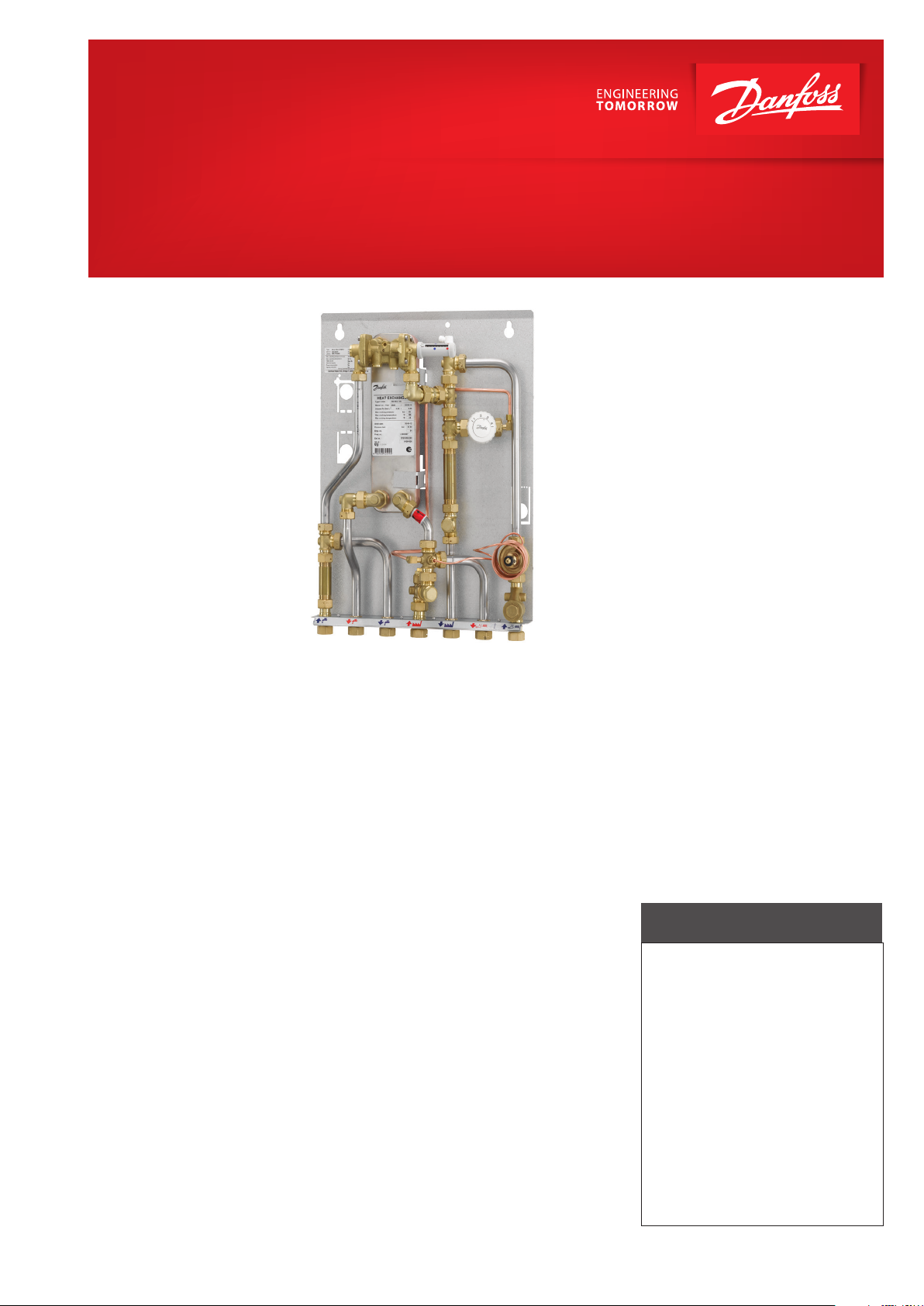
Akva Vita II TDP-F
Flat station for single-family, semi-detached and terraced houses as well as flats
Application
The Akva Vita II TDP-F is a flat station featuring high performance and simple operation. The Akva Vita II TDP-F is especially suitable for two-pipe systems. The Akva Vita II
TDP-F is developed for flat systems supplied
from a secondary connected district heating
sy-stem, a block heating system or a centrally
located boiler system in a block of flats. The
Akva Vita II TDP-F is available as built-in variant with a recess box or as wall-mounted
variant and is prepared for implementation
with the Danfoss Redan distribution systems
for floor heating or radiator heating.
District heating (DH)
The flat station is prefabricated with interconnecting components such as differential pressure controller, strainer, thermostatic
bypass FJVR, sensor pockets and fitting piece
for insertion of a heat meter.
Heating (HE)
The heating side is designed for direct ge-neration of heat in a two-pipe system. The differential pressure controller sets the optimum
operating conditions for radiator thermostatic valves in order to enable individual temperature control in each room. In order to
enable a time depending temperature
control program the Akva Vita II TDP-F can be
equipped with a zone valve RA-C and electric
actuator TWA-A. A return temperature limiter,
type FJVR, for automatic regulation of the return
temperature from the radiators or the floor heating system can be mounted (not part of the
delivery).
Domestic hot water (DHW)
The domestic hot water is prepared in the heat
exchanger based on the flow principle. Supreme ease of operation is obtained via the combined hydraulic and thermostatic regulation
of domestic hot water through the self-acting
controller with integrated differential pressure
controller - the PTC2+ P controller, thereby
guaranteeing a constant domestic hot water
temperature at all times.
The use of hydraulic regulation widely prevents
the formation of lime scale and bacteria due to
the fact, that the valve closes immediately after
the tapping is ended. Furthermore the combined control function ensures that variations in
temperature in the district heating network are
reduced. A thermostatic bypass enables tapping of hot water without any delay, – ensuring
the best possible efficiency and economy. For
regi-stration of the cold water consumption
the Akva Vita II TDP-F is equipped with a fitting
piece for mounting of a cold water meter in the
DCW inlet
Domestic hot water circulation
The Akva Vita II TDP-F is equipped with bypass function as a standard, but it is prepared for DHW circulation. Equipment for DHW
circulation is optional and must be ordered
separately.
Construction
All pipes are made of stainless steel.
The connections are made by nuts and
gaskets. The Akva Vita II TDP-F can be deli-vered with white-lacquered steel cover for recess mounting or for wall mounting.
FEATURES AND BENEFITS
• Flat station for district heating
• Direct heating, DHW heating based
on flow principle
• Capacity: 15 kW HE, 41 kW DHW
• Minimum space required for
installation built-in or wallmounted variant
• Service-friendly
• Pipes and plate heat exchanger
made of stainless steel
• Minimized risk of lime scale and
bacteria formation
www.danfoss.com
POS.
Qty.
PART NUMBER
Description
1 1
440218-test
Bagplade TDP-F
2 1
E120004203 XB06H-1, 26 pl
3 1 329133
Monteringsbøsning 2x 3/4" Oml.
4 4 171020
5 1 316004
Passtk. 3/4" x 80
6 1 125304
7 20 145056
Pakning 3/4" udst. 24x17,5x3 m EPDM 282
8 1 8211317
Rør Ø18
9 1 125037
Tee 3/4"M x 3/4"N x M14x1
10 1 161087
11 2 125123
12 1 8300031
Rør Ø18
13 1 905023
14 1 361003
15 1 830003
16 1 152160
17 1 530046
18 1 125309
19 1 326069
20 1 828102
21 1 125310
22 1 933301
23 1 133006
24 2 127028
25 1 125315
26 1 125302
27 1 138041
Udluftning drejelig
28 1
g412100
29 1 5300192
Rør Ø18
30 1 135120
31 1
125290-pr
32 1 12510404
33 1
5300191
Rør Ø18
34 1 326062
35 1 152124
36 1 125141
37 1 530019
Rør Ø18
D
C
B
A
87
6
5
4
3
2
1
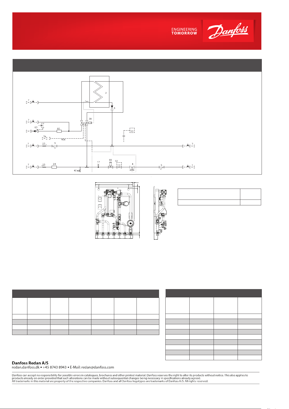
CIRCUIT DIAGRAM EXAMPLE
DHW
DCW
DCW
Connection for circ.
Circ.
DH
Supply
DH
Return
Design specifications:
Nominal pressure (prim/sec.): PN 10 / PN 10
Max. supply temperature: 90 ºC
DCW static pressure: p
Brazing material (HEX): Copper
= 2.0 bar
min
Weight excl . cover: 25 kg
Cover: White-lacquered
steel
Electrical supply: 230 V AC
Dimensions (mm):
Without cover: H 572 x W 458 x D 150
Connections size:
DH, HE, DHW, DCW: G ¾” (int. thread)
Circ: R½” (ext. thread)
2 Plate heat exchanger DHW
4 Differential pressure controller
AVPL with changeable setting
5 Strainer
6 Non-return valve
17 Air vent
23 Sensor pocket for heat meter
24 Fitting piece for heat meter
(Option: Room thermostat)
Circ.
(Option)
Bypass
(Standard)
440
350 40 50
25 65 65 65 65 65 65 25
18
24,2
551
21
Connections:
1. Domestic cold water (DCW) inlet
2. Domestic hot water (DHW)
3. Domestic cold water (DCW) outlet
4. District heating (DH) supply
5. District heating (DH) return
6. Heating (HE) supply
7. Heating (HE) return
3/4” x 110 mm
44
38 PM2+P controller
40 Danfoss FJVR thermostat for
bypass/circulation
60 Fitting piece for cold water meter
3/4” x 110 mm
------------------------------------------------Options:
7 Ball valve
7A Ball valve for circulation
40A Connection for circulation
52 Zone valve + actuator
53 Room thermostat Danfoss
63 Safety valve
69 Return temperature limiter FJVR
HE
Supply
HE
Return
Code No‘s:
Akva Vita II TDP-F w/o cover, with
heat exchanger type (DHW):
XB 06H-1 26
Code no.:
004U8597
Options:
• White cover for wall-mounted variant, closed or open at
the bottom or white recess box for built-in variant
• Return temperature limiter Danfoss FJVR
• ¾ ball valves for unit
• Insulation
• Set with safety valve 6 bar and non-return valve
• Ball valve ½“ for circulation 48 mm
• Thermometer - 120° C for mounting in ball valve
• Zone valve RA-C / Actuator TWA-A
• Circulation set with or without pump
• Room thermostats
DHW: Capacity examples, 5 °C/60 °C
CapacitykWPlate heat
exchanger
Supply flow
Primary
41.0 XB 06H-1 26 65 31.7 10.60 0.49 1060
41.0 XB 06H-1 26 70 24.0 10.60 0.27 770
41.0 XB 06H-1 26 80 17.0 10.60 0.15 560
41.0 XB 06H-1 26 90 13.0 10.60 0 .10 460
* Heat meter not incl.
© Danfoss | DHS-SRMT/ PL | 2018 . 02
Return flow
Primary
°C
°C
DHW
tap load
Pressure loss
Primary
l/min
bar
Flow rate
Primary
l/h
Heating: Capacity examples
Heating
capacity
Heating
circuit ∆t
°C
5 15 0.22 680
10 15 0.54 880
15 15 1.04 1080
5 20 0.17 630
10 20 0.35 780
10 30 0.22 680
15 30 0.35 780
20 30 0.54 880
20 40 0.35 780
Calculated at 70% heating flow + 41.0 kW DHW 80/17-5/60.
Pressure loss
Primary
*bar
Flow rate
Primary
l/h
VL.HE.Y2.02
 Loading...