

Fact sheet
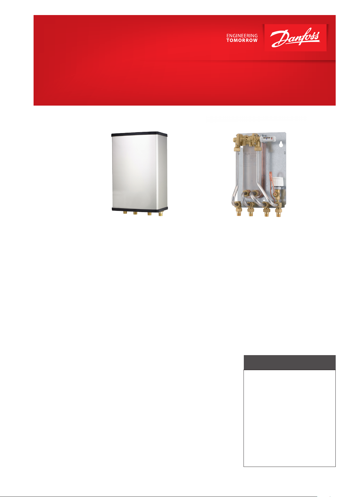
Akva Vita II
Instantaneous water heater for single-family houses and flats
Application
The Akva Vita II is an instantaneous water
heater featuring high performance and
simple operation. It is especially suitable for
single-family houses and for systems with a
similar domestic hot water requirement.
The Akva Vita II can be used directly on district heating networks with a differential
pressure of max. 2.5 bar.
Construction
The Akva Vita II water heater is prefabricated with a brazed, highly efficient Danfoss
plate heat exchanger for domestic hot water production, a domestic hot water controller Danfoss PM2+P, as well as a Danfoss
FJVR thermostat for control of the bypass/
circulation temperature. All pipes are made
of stainless steel and the connections are
made by nuts and gaskets. As an option and
if approved by local regulations the water
heater can be supplied with a Danfoss AVE
expansion unit to avoid having to establish
a discharge pipe.
Design
The Akva Vita II is designed for wall-mounting and the design emphasizes a user-friendly placement of the controllers. The Akva
Vita II can be supplied with a brushed or white-lacquered stainless steel cover in an elegant and modern design.
Bypass (thermostatic circulation)
The water heater is supplied with a thermostatically controlled bypass, which ensu
res that hot water is produced immediately,
when tapping starts. The bypass temperature is set with due consideration of the best
possible DHW comfort and economy.
Domestic hot water circulation
The water heater is prepared for domestic
hot water circulation. If the household piping includes hot water recirculation the
water heater must be connected to the hot
water recirculation system and a circulation pump and a non-return valve must be
mounted on the circulation pipe and a safety valve must be mounted in the DCW inlet. The pump must be installed so that it
pumps towards the water heater. Domestic
hot water circulation ensures that hot water
is available at the tapping point without waiting time and waste of water. The circulation temperature is set independently of the
set DHW temperature. This ensures the best
possible DHW comfort, very low standby
losses and thus a very good district heating
economy. Please note that Akva Vita II with
AVE expansion unit should not be used on
systems with domestic hot water recirculation.
Heat exchanger for DHW heating
The water heater is based on a brazed, highly
efficient plate heat exchanger type XB 06H-1
26, which is controlled by a pressure controlled DHW controller, Danfoss PM+P with integrated differential pressure controller and
e
save
exchanger is cold during standby. After
function, which ensures that the heat
TM
completion of the tapping process, the controller immediately blocks the district heating flow, to avoid standby losses and to
protect the heat exchanger from the formation of lime scale and growth of bacteria.
The heat exchanger is cold during standby,
so the heat loss is very low. The integrated
differential pressure controller compensates
for variations in supply temperature and varying differential pressure and thereby ensures a constant hot water temperature at
all times.
Service and maintenance
The water heater is very service-friendly and
easy to install. It is mounted on the wall and
as all pipes are placed in pipe bracket distance, it is possible to establish a nice piping.
FEATURES AND BENEFITS
• COLD heat exchanger during standby, no standby losses
• DHW controller PM2+P with integrated
differential pressure controller and energy- saving function
• Pipes and heat exchanger made of
stainless steeel, connections with EPDM
gaskets
• Minimized risk of lime scale and bacteria
formation, no Legionella
• Capacity: 35 kW
www.danfoss.com
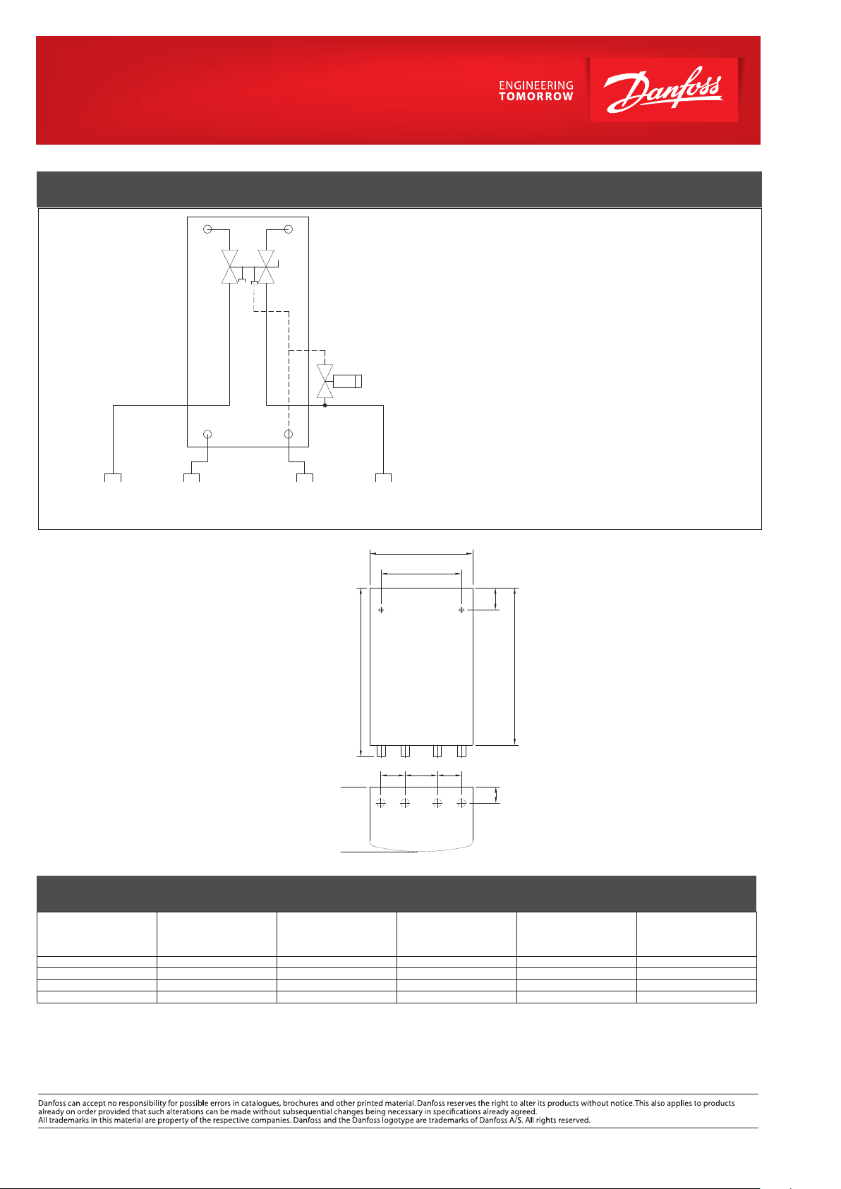
CIRCUIT DIAGRAM – EXAMPLE
DHW circ.
DCW
DHW DH
Bypass
Supply
DH.
return
1. Danfoss copper brazed plate heat exchanger
in stainless steel AISI 316, type XB 06H-1 26.
2. Domestic hot water controller type Danfoss
PM2+P.
3. Bypass/circulation thermostat Danfoss FJVR.
4. Connection of capillary tube from Danfoss
FJVR acting as bypass thermostat (standard
function).
5. Connection of capillary tube from Danfoss
FJVR acting as circulation thermostat (DHW
recirculation).
6. Connection piece for circulation pipe, if any.
Note: Circulation set is not part of the delivery and must
be ordered separately and mounted on site.
Design specifications:
Nominal pressure (prim/sec.): PN 16 / PN 16
Max. supply temperature: 120 ºC
DCW static pressure: p
Min. ∆P: See capacity examples
= 2.0 bar
min
Chloride compounds: Max. 300 mg/l
Weight incl. cover: 9 kg
(incl. packing)
Cover: Brushed steel
Dimensions (mm):
Without cover: H420xW250xD150
With cover: H420xW255xD160
Connections sizes:
DH, DCW, DHW: R ½“ ET (ext. thread)
Circulation: R ½“ ET (ext. thread))
CAPACITY, WEIGHT AND DIMENSIONS
DHW: CAPACITY EXAMPLES, 10°C/45°C
DHW
Capacity
kW
32.3 55 21. 8 13.16 0.28 840
32.3 60 18.9 13.16 0.18 680
41.0 60 20.4 16.96 0 .31 900
41.0 70 16.8 16.86 0.17 670
*) Stated pressure loss values are complete, incl. pipes, heat exchanger and valves.
Supply flow
Primary
°C
Return flow
160
Primary
°C
420
1 2 3 4
60 80 60
1 2 3 4
Top view
255
200
(5)
DHW
tap load
l/min
Recirculation:
Remember to order circulation set for systems
that feature DHW recirculation.
55
40
Connections:
1. District heating (DH) supply
2. District heating (DH) return
3. Heating (HE) return
4. Heating (HE) supply
5. Domestic hot water (DHW)
391
6. Domestic cold water (DCW)
Options:
• Cover, white-lacquered steel, with door
• Electronic controller Danfoss ECL310
• Circulation set for DHW recirculation
• Safety function - safety thermostat + actuator
• Connection of pipes can be established in the top
or in the bottom of the substation
• Pipe insulation
• Mounting of heat meter (supplied by customer)
• Supplementary fitting set for change of fitting
piece size ¾ x 110 mm to fitting piece size 1“ x 190
mm
Pressure loss*
Primary
bar
Flow rate
Primary
l/h
Danfoss Redan A/S · District Energy · Omega 7 · DK-8382 Hinnerup
Tel.: +45 87 43 89 43 · Fax: +45 87 43 89 44 · redan@danfoss.com · www.redan.danfoss.dk
© Danfoss | DHS-SRMT/ PL | 2016 . 05
VL.GP.J2.02
 Loading...