

MAKING MODERN LIVING POSSIBLE
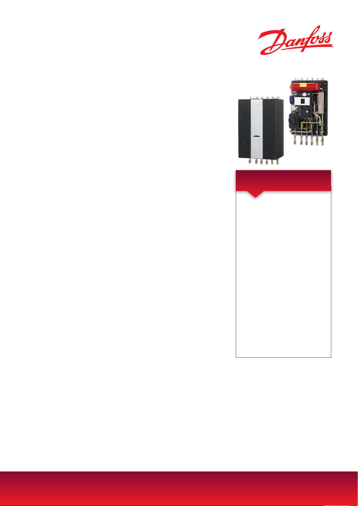
Akva Lux II VXi
Fully insulated substation for single-family, semi-detached and
terraced houses
District heating substation for indirect heating and instantaneous domestic
hot water. Innovative DHW temperature control, PTC2+P with energy-saving
function. For wall-mounting with pipes connection in top or bottom
Application
The Akva Lux II VXi is a fully insulated substation featuring high performance and
simple operation. The Akva Lux II VX is especially suitable for two-pipe systems and
systems with floor heating. The substation
is available in several capacity variants.
Construction
The Akva Lux II VXi substation is available in two main types with a plate heat
exchanger for domestic hot water production type XB 06H-1 26 for 1-2 dwellings and heat exchanger type XB 06H-1
40 for 3-4 dwellings. On the heating side
the substation is available with heat exchanger type XB 06H-26, 40 and type XB
06L-1 24 for floor heating. The Akva Lux
II VXi also features safety and non-return
valve on the cold water connection, ball
valves, sensor pockets, differential pessure controller, expansion vessel, energy-efficient circulation pump, thermostat, strainers, an energy-saving domestic hot water controller Danfoss
PTC2+P, as well as a Danfoss thermostat for control of the bypass/circulation
temperature and a flexible fitting piece for mounting of heat meter in the district heating return and supply line. The
substation is prepared for domestic hot
water recirculation.
ture is controlled by an
controller with weather compensation.
Design
The Akva Lux II VXi is designed for wallmounting and during the construction there has been much emphasis on
a user-friendly placement of all components. The Akva Lux II VXi is supplied
fully insulated with insulation cover in
modern design.
The heating tempera-
electronic ECL 310
Heat exchanger for DHW heating
The substation is based on a brazed,
highly efficient plate heat exchanger,
which is controlled by a thermostatic
and pressure controlled DHW controller, Danfoss PTC2+P with integrated differential pressure controller and energysaving function, which ensures that the
heat exchanger is cold during standby.
Bypass (thermostatic circulation)
The water heater is supplied with a thermostatically controlled bypass, which
ensures that hot water is produced immediately, when tapping starts. The bypass temperature is set with due consideration of the best possible DHW comfort and economy. The substation is easily rebuilt for application in systems with
DHW recirculation.
Domestic hot water recirculation
The substation is prepared for connection to systems with DHW recirculation.
Switching to DHW recirculation is possible from a constructional point of view,
requiring only mounting of a separate
circulation set (see options). The circulation temperature is set independently
of the set DHW temperature. This ensures the best possible DHW comfort, very
low standby losses and thus a very good
district heating economy.
Mounting of heat meter
The substation is equipped with 3/4” fitting pieces for fitting of a heat meter in
the DH return flow.
Service and maintenance
The substation is very service-friendly
and easy to install. It is mounted on the
wall and as all pipes are placed in pipe
FEATURES AND BENEFITS
• Fully insulated substation for large singlefamily houses
• Indirect heating, DHW heating based on
flow principle
• Electronic control of heating (HE)
temperature
• Innovative, energy-saving controller PTC2
+ P in combination with high performance
heat exchanger for on-demand water
heating without no-load losses function
• Pipes connection in top or bottom of
substation = Savings in installations costs
• Pipes and heat exchanger made of stainless
steel, connections with EPDM gaskets.
• Minimized risk of lime scale and bacteria
formation
• Electrical wiring from factory - Plug & Play
• Capacity: up to 53 kW DHW ,
Radiator 10-34 kW, Floor heating 8 kW
bracket distance, it is possible to establish a nice piping either in the top or in
the bottom of the substation. The white
removable center part in the front insulation allows easy access to components
for regulation and maintenance purposes.
districtenergy.danfoss.com
550
55
360
113,5
1: Fjv. frem
2: Fjv. retur
3: Varme retur
4: Varme frem
5: V.V.
6: K.V
7: Cirk.
POS.
Cirk.ned/QTY.
PART NUMBER
Description
1
1
145H3693
Beslag f. VX-Isol. Instrumentpanel
2
1
145H3695
Beslag VX-Isol. FJV-R
3
1
145H3696
Beslag VX-Isol. FJV-R
4
1
145H3697
Beslag f. VX-Isol Fjv-R
5
1
145H3699
Bagplade VX-Isoleret
6
1
145H3701
Grundfos UPM3 Auto 15-70 130 EUX9
7
1
145H3739
Vinkel 3/8" M mess.
8
1
145H3740
Brystnippel F68 6x3/8" klemring
9
1
145H3749
10
1
145H3753
Cimm 12L
11 1
145H3803
Manometer 0-4 bar m. slæbeviser
12 1 145H3803_1
13 1 145H3803_2
14 1
145H3811
Beslag f. veksler
15 2
145H3812
Beslag f. bundplade isolering
16 1
145H3813
Beslag f. cirk.
17 1
145H3814
Frontplade nederste
18 1
145H3816
Frontplade REDAN
19 6
145H3817
Skrue M5x80 Cyl. hoved indv. 6 kt. DIN
912
20 2
145H3818
Spånskrue 6x30
21 3
145H3819
Skrue EPP 15x32
22 2
145H3820
Skærmskive Ø5.5/30
23 1
145H3821
Ledningsholder
24 1
145H3822
Låseskinne
25 1
145H3825
Tape m. symboler
26 1
145H3826
Label -+
27 1
145H3827
Kapilarrør Ø6x0.7
28 1
145H3828
Kap.rør Ø4x1
29 1
145H3830
Kap. rør Ø4x1
30
2
101001
Pladeskrue 4.2x13
31
2
101010
Pladeskrue 4.2x8
32
1
102218
Skrue M5x65 Cyl. hoved indv. 6 kt. DIN
912
33
9
113206
Popnitte Ø4.8x10 Alu
34
1
125037
Tee 3/4"M x 3/4"N x M14x1
35
1
125121
36
1
125123
37
1
125162
38
1
125165
39
3
125301
40
1
125302
41
1
125305
42
1
125306
Danfoss Standard
A3
1:7.5
Material
SizeScale
Projection
Design
Replace
VX
Designation
E
D
C
B
A
87
6
5
4
3
2
1
kg
Weight
General tolerance accuracy
Akva Lux II VXi
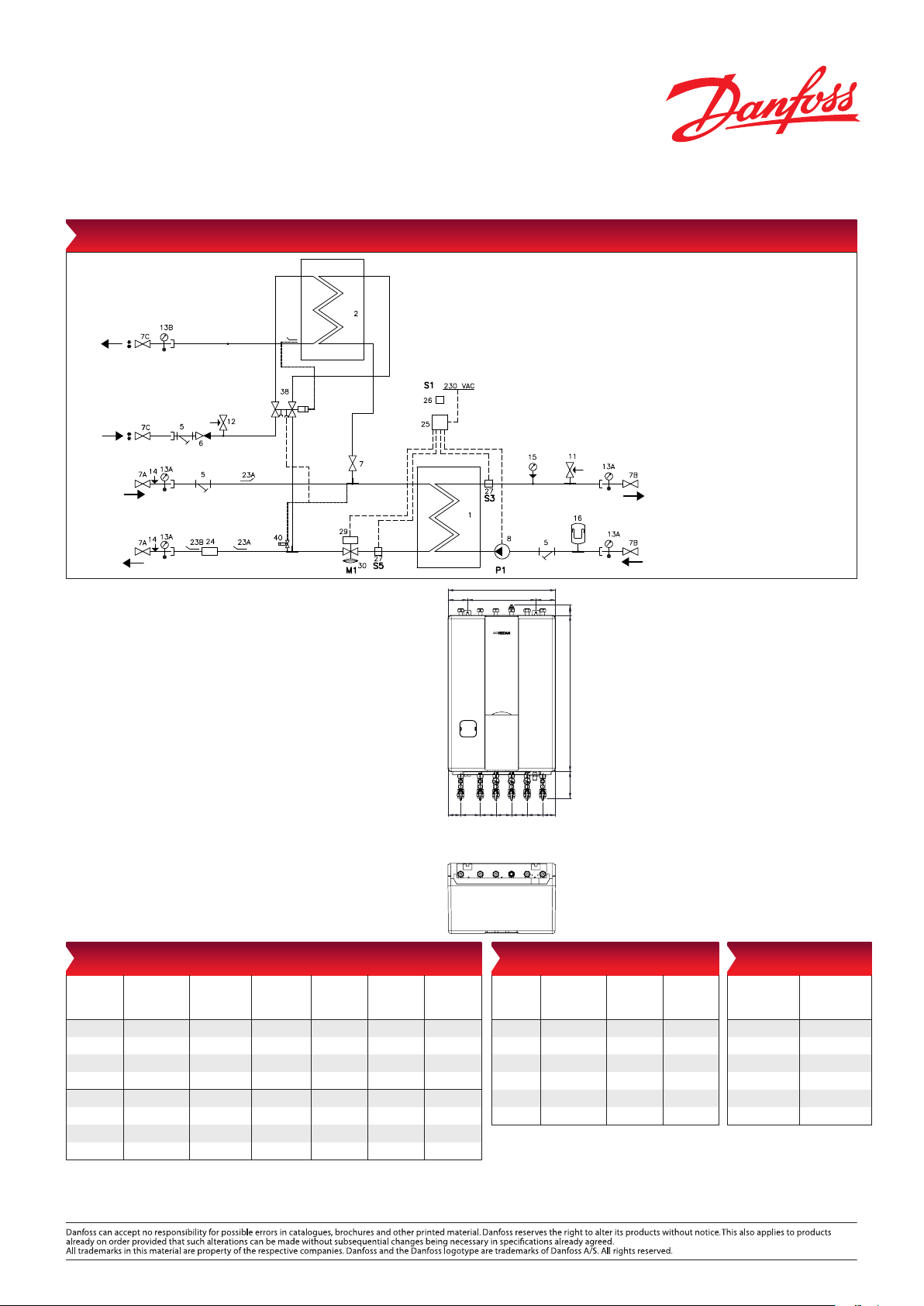
Circuit diagram – example, Akva Lux II VXi with electronic controller ECL 310/A337
16 Expansion vessel
23A Sensor pocket ½”/10x1, plug
M10 for heat meter
23B Plug ½” with O-ring
24 Fitting piece for heat meter
3/4” x 110 mm
25 Controller Danfoss ECL310/
A337
26 Outdoor sensor, ESMT
27 Sensor Danfoss, ESMC
29 Actuator HE, AMV 150
30 Multifunctional control valve
AVQM
DHW
DCW
(Option: Circ.)
1 Plate heat exchanger HE
2 Plate heat exchanger DHW
5 Strainer
6 Non-return valve
7A Ball valve ¾” ext/ext, 120 mm
7B Ball valve ¾” int/ext, for
thermometer
7C Ball valve ¾” ext/ext, DHW/DCW
8 Circulation pump HE
11 Safety valve HE
12 Safety valve DHW
13 Thermometer
15 Manometer
38 PT°C 2 controller
40 Thermostat for bypass/
HE
DH
Supply
Bypass
Supply
circulation
(standard)
DH
Reurn
Design specifications:
Nominal pressure (prim/sec.): PN 16 / PN 3
Max. supply temperature: 120 °C (design temp.)
Min. ΔP: See capacity examples
Brazing material (HEX): Copper
Weight incl. cover: Max. 55 kg
(incl. packing)
Insulation: Polypropylene EPP λ 0.039
Dimensions (mm):
With insulation: H 980 × W 550 × D 360
Eletrical supply: 230 V AC
Connections sizes:
DH: G ¾“ ET (ext. thread)
DCW, DHW, HE: G ¾“ ET (ext. thread)
Circulation: R ½“ ET (ext. thread)
Recirculation:
100 350 100
7
65 100 80 80 80 80 65
1 2 3 4 5 6
1 2 3 4 5
6
54 800 136
HE
Return
Connections:
1. District heating (DH) supply
2. District heating (DH) return
3. Heating (HE) return
4. Heating (HE) supply
5. Domestic hot water (DHW)
6. Domestic cold water (DCW)
7. Circulation
Options:
• Circulation set for DHW recirculation
• KFE filling and drain valve ¼” (for mounting in ball
valve
• Connection of pipes can be established in the top
or in the bottom of the substation
• Mounting of heat meter (supplied by customer)
Remember to order circulation set for systems that feature DHW
recirculation.
DHW: Capacity examples 10 °C/45 °C
DHW
capacity
[kW]
Plate heat
exchanger
Supply flow
primary
[°C]
Return flow
primary
[°C]
DHW
tap load
[l/min]
Pressure
loss
Primary
Flow rate
primary
32.3 XB 06H-1 26 55 21.8 13.16 0.36 840
32.3 XB 06H-1 26 60 18.9 13.16 0.24 680
32.3 XB 06H-1 40 55 19.0 13.16 0.27 770
32.3 XB 06H-1 40 60 17.3 13.16 0.24 680
41.0 XB 06H-1 26 60 20.4 16.83 0.41 890
41.0 XB 06H-1 26 70 16.8 16.83 0.23 660
53.0 XB 06H-1 40 60 19.1 21.67 0.55 1110
53.0 XB 06H-1 40 70 15.7 21.67 0.31 840
Danfoss Redan A/S · District Heating · Omega 7, Søften · DK-8382 Hinnerup · Denmark
Tel.: +45 87 43 89 43 · Fax: +45 87 43 89 44 · redan@danfoss.com · www.redan.danfoss.dk
VL.JV.V1.02 © Danfoss 02/2017 DKDHR
[l/h]
top view
Heating: Capacity examples
Heating
capacity
2
Floor heating
3
Calculated at 70% of the heating capacity + DHW capacity of 32.3 kW with heat exchanger XB06H-1 26
at a district heating supply temperature of 55
Plate heat
exchanger
19 XB06H-1 26 70/40 35/60
31 XB06H-1 40 70/40 35/60
8 XB06L-1 24
7 XB06H-1 40270/31 30/35
10 XB06H-1 40 60/30 25/55
34 XB06H-1 26 90/44 40/70
HE circuit
primary
2
70/31 30/35
[° C]
HE circuit
secondary
[° C]
2
2
4
°C or 605 °
Pressure loss
primary
(total3) bar
0.40
0.87
0.17
0.17
0.29
0.49
C (DHW 10/45°C) or 656 °
Tot al
5
5
5
5
4
6
Flow rate
primary
(total3) [l/h]
5
920
5
1160
5
660
5
650
4
880
6
840
C (DHW 10/50 °C).
 Loading...