

Danfoss Akva Lux II VX2, Akva Lux II VX2-E, Akva Lux II VX3, Akva Lux II VX3-E Operating guide
MAKING MODERN LIVING POSSIBLE
Danfoss District Energy
Akva Lux II VX2, VX2-E, VX3, VX3-E
Instructions for installation and use
Instructions for installation and use Akva Lux II VX substations
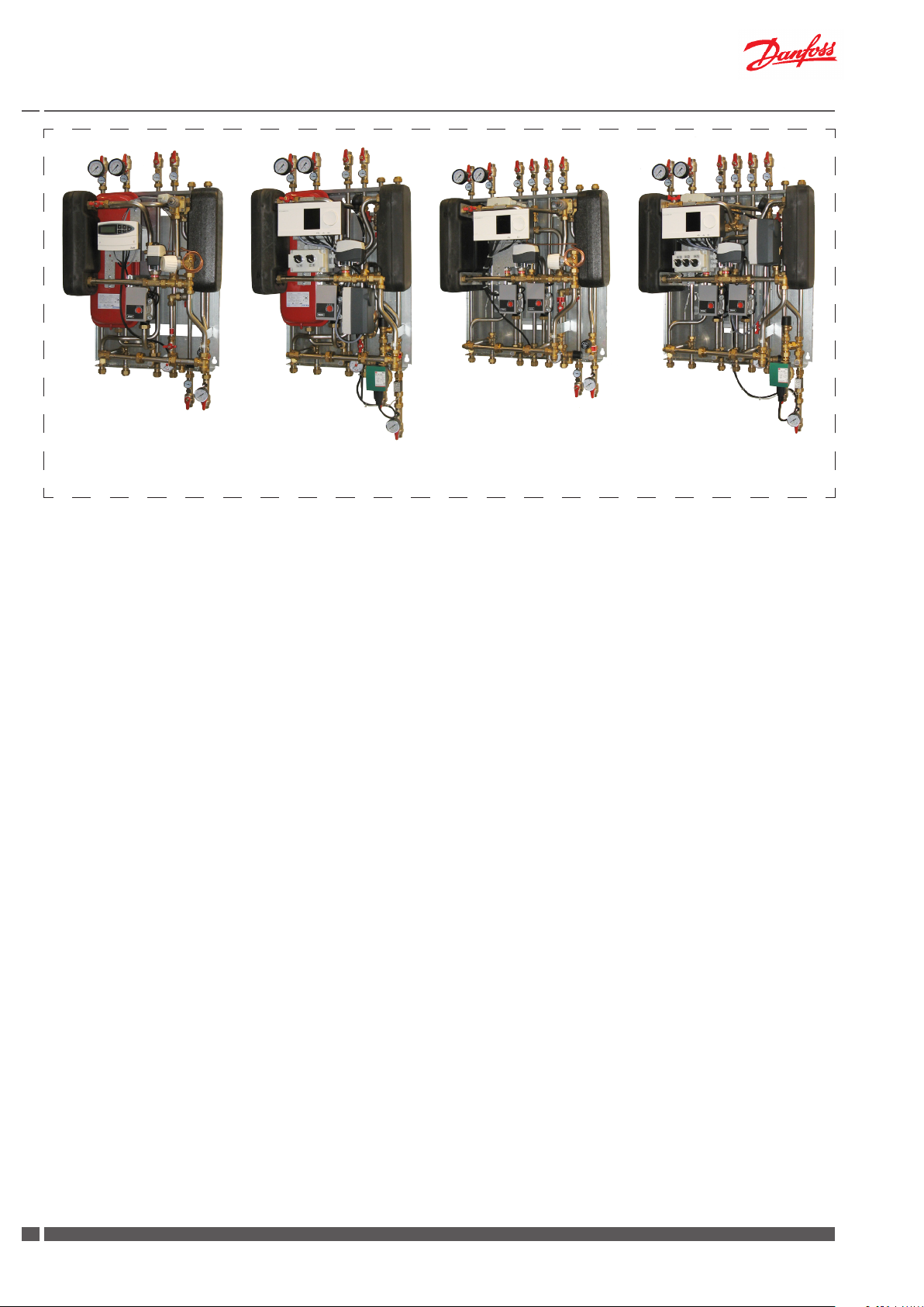
Akva Lux II VX2 Akva Lux II VX2-E Akva Lux II VX3 Akva Lux II VX3-E
1. Contents
1.0 Contents ...................................................................................................................................................................................................................................... 2
2.0 Safety notes ...............................................................................................................................................................................................................................3
3.0 Storage and Handling ............................................................................................................................................................................................................ 3
4.0 Disposal ....................................................................................................................................................................................................................................... 3
5.0 Diagram - Examples ................................................................................................................................................................................................................ 4
5.1 Akva Lux II VX2 ..................................................................................................................................................................................................................4
5.2 Akva Lux II VX2-E ..............................................................................................................................................................................................................5
5.3 Akva Lux II VX3 ..................................................................................................................................................................................................................6
5.4 Akva Lux II VX3-E ..............................................................................................................................................................................................................7
6.0 Main components ................................................................................................................................................................................................................... 8
6.1 Akva Lux II VX2 ..................................................................................................................................................................................................................8
6.2 Akva Lux II VX2-E ..............................................................................................................................................................................................................9
6.3 Akva Lux II VX3 ............................................................................................................................................................................................................... 10
6.4 Akva Lux II VX3-E ........................................................................................................................................................................................................... 11
7.0 Getting started ...................................................................................................................................................................................................................... 12
8.0 Mounting ................................................................................................................................................................................................................................ 13
8.1 Variable connection possibilities ............................................................................................................................................................................ 13
8.2 DHW recirculation Akva Lux II VX2 & Akva Lux II VX3......................................................................................................................................14
8.2.1 Mounting of circulation set for Akva Lux II VX2 & VX3 ......................................................................................................................... 14
8.2.2 Mounting of circulation set Akva Lux II VX2-E and VX3-E ................................................................................................................... 14
8.3 Safety thermostat ........................................................................................................................................................................................................ 15
8.4 Expansion vessel .......................................................................................................................................................................................................... 16
8.5 Heat meter, Fitting piece........................................................................................................................................................................................... 17
8.6 Test and connections ................................................................................................................................................................................................. 17
8.7 Mounting of outdoor temperature sensor ........................................................................................................................................................ 17
8.8 Safety valves .................................................................................................................................................................................................................. 17
9.0 Filling, Start-up ...................................................................................................................................................................................................................... 18
10.0 Manometer and relling .................................................................................................................................................................................................... 18
11.0 Electrical connections ......................................................................................................................................................................................................... 19
12.0 Description of Akva Lux II VX variants ........................................................................................................................................................................... 20
12.1 Akva Lux II VX2 (ECL 110) ......................................................................................................................................................................................... 20
12.2 Akva Lux II VX2-E (ECL 310/A266) ......................................................................................................................................................................... 22
12.3 Akva Lux II VX3 (ECL210/A260) .............................................................................................................................................................................. 25
12.4 Akva Lux II VX3-E (ECL310/A376) .......................................................................................................................................................................... 28
13.0 Circulation pumps - Heating ............................................................................................................................................................................................. 32
14.0 Circulation pumps - Domestic hot water ..................................................................................................................................................................... 33
14.1 Wilo-Stratos ECO-Z (Circulation set 810.441) .................................................................................................................................................... 33
14.2 Wilo-Star-Z NOVA (Circulation set 810.443) ...................................................................................................................................................... 33
15.0 Maintenance ........................................................................................................................................................................................................................... 34
15.1 Maintenance plan (recommendations) .............................................................................................................................................................. 35
16.0 Troubleshooting .................................................................................................................................................................................................................... 36
16.1 Troubleshooting - Heating ...................................................................................................................................................................................... 36
16.2 Troubleshooting - Domestic hot water ............................................................................................................................................................... 38
17.0 EC-Declaration of Conformity .......................................................................................................................................................................................... 40
2
DKDHR VI.GP.V2.02 Danfoss District Energy
Instructions Akva Lux II VX
2.0 Safety notes
Instructions
This operating manual should be read carefully before installation and
start-up of the substation. The manufacturer accepts no liability for
damage or faults that result from non-compliance with the operating
manual.
Please read and follow all the instructions carefully to prevent accidents, injury and damage to property. The risk of persons being injured
and equipment damaged increases considerably if the recommended
permissible operating parameters are exceeded.
Installation, assembly work, rst start-up and maintenance work may
be carried out only by qualied and authorized personnel in compliance with the safety regulations (both heating and electrical work).
Connection
The substation must be equipped with features that ensure that the
substation can be separated from all energy sources (also power
supply).
Warning! Hot surfaces
Parts of the substation may be very hot and can cause burn injuries. Be very careful when you are in the immediate vicinity of the
substation.
Energy source
The substation is designed for district heating as the primary source
of energy. However, also other energy sources can be used where the
operating conditions allow it and always are comparable to district
heating.
Application
The substation is designed only to operate with water or a water-glycol
mixture (up to 40%), and other heating media may not be used.
Connect the substation to the house installation in a frost-free room,
where the temperature does not exceed 50 °C and the humidity does
not exceed 80%. Do not cover or wall up the substation or in any other
way block the entrance to the station.
Choice of material
Choice of materials always in compliance with local legislation.
Corrosion protection
The maximum chloride compounds of the ow medium should not
be higher than 300 mg/l. The risk of equipment corrosion increases
considerably if the recommended permissible chloride compounds
are exceeded.
Safety valve(s)
We recommend mounting of safety valve(s), however, always in compliance with local regulations.
Sound level.
≤ 55 dB.
Warning of high pressure and high temperature
The maximum supply temperature in the district heating network
can be up to 110°C and the operating pressure can be up to 16 bar.
This may result in a risk of scalding from touching the substation
and from outow of the medium (water/steam). Exceeding the
substation design data and operating parameters for pressure and
temperature carries an appreciable risk of personal injury and/or
damage to property.
Emergencies
In the event of re, leaks or other hazards, immediately shut o all
sources of energy to the substation, if possible and call for appropriate assistance. If the domestic hot water is discoloured or malodorous, shut o all ball valves on the substation, notify all users and call
for professional assistance immediately.
Warning of damage during transport
On reception of the substation, and before installing it, check for
any evidence of damage during transport.
The substation must be handled and moved with the greatest care
and attention.
IMPORTANT - Tightening of connections
Before adding water to the system, ALL pipe connections MUST be
retightened, as vibrations during transport may have caused leaks.
Once the substation has been lled and the system has been put
into operation, ALL connections must be tightened once more.
(Do not overstrain! - See item 8.6, page 17)
3.0 Storage and Handling
Before installation, the units must be stored in a dry, heated (i.e. frostfree) room.
(Relative humidity max. 80% and storage temperature 5-70 °C).
The units must not be stacked higher than the limit at the factory . Units
supplied in cardboard packaging must be lifted using the handles incorporated in the packaging. Units must be placed on pallets for transport/
moving across large distances.
As far as possible, do not lift the substation by the pipes. Lifting by the
pipes may cause leaks. REMEMBER to retighten.
Handling
We recommend minimum two people to lift the substation.
We recommend that you wear suitable safety footwear while
handling and installing the substation.
4.0 Disposal
Dispose of the packaging in accordance with the local regulations for
disposal of used packaging materials.
The substation is made of materials that cannot be disposed of together
with household waste.
Close all energy sources and disconnect all connection pipes. Disconnect
and dismantle the product for disposal in accordance with the applicable
local regulations for the disposal of the individual components.
Danfoss District Energy VI.GP.V2.02 DKDHR
33
Instructions Akva Lux II VXInstructions Akva Lux II VX
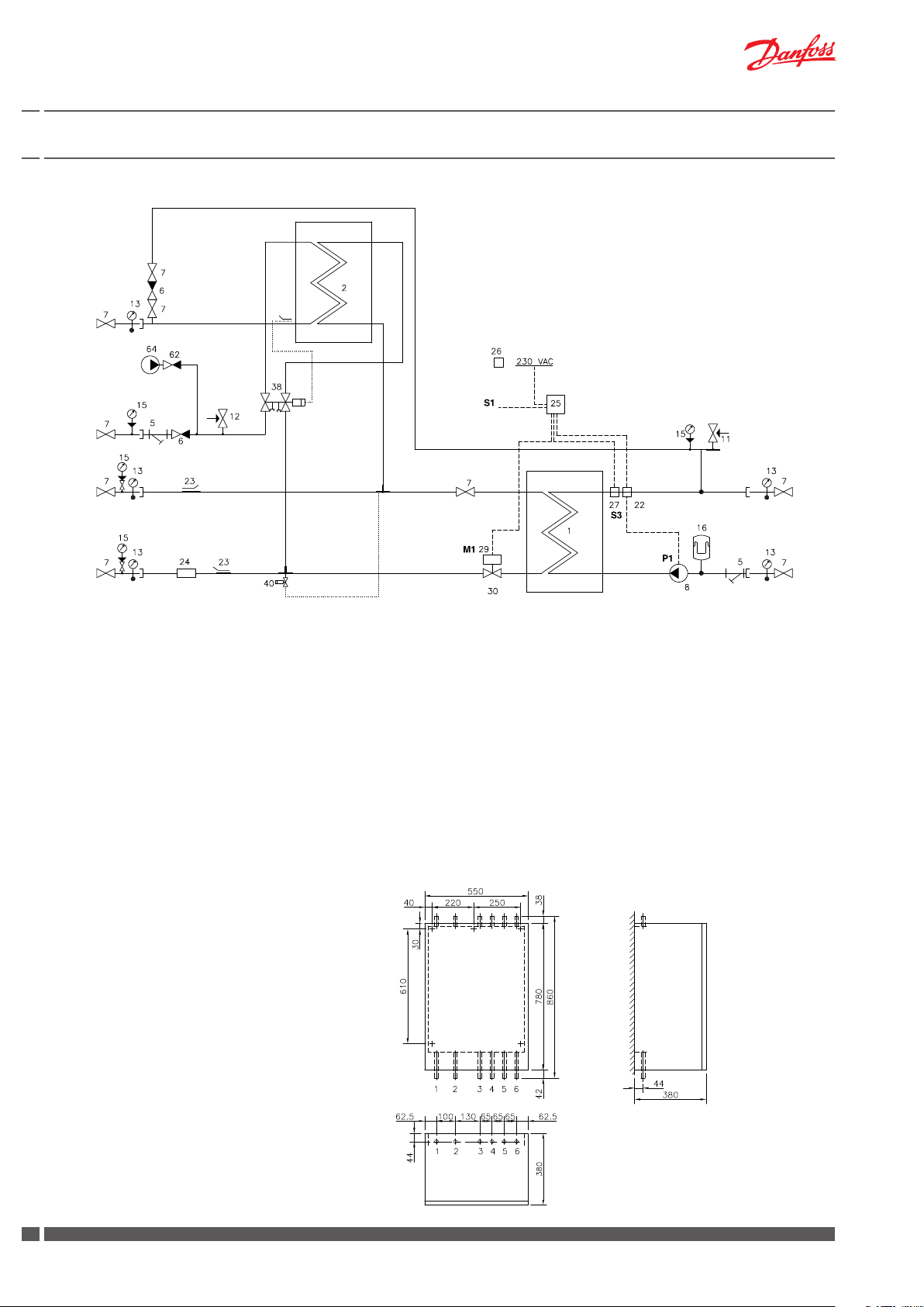
5.0 Diagram - Examples
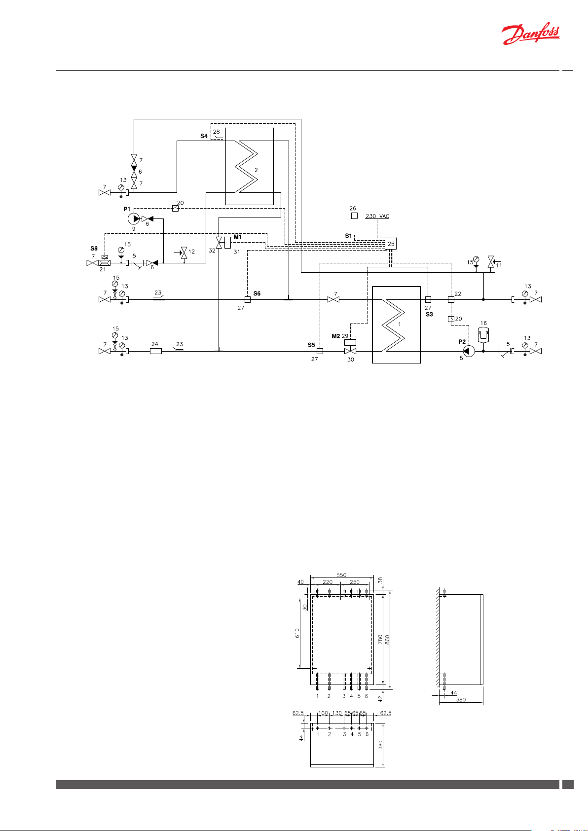
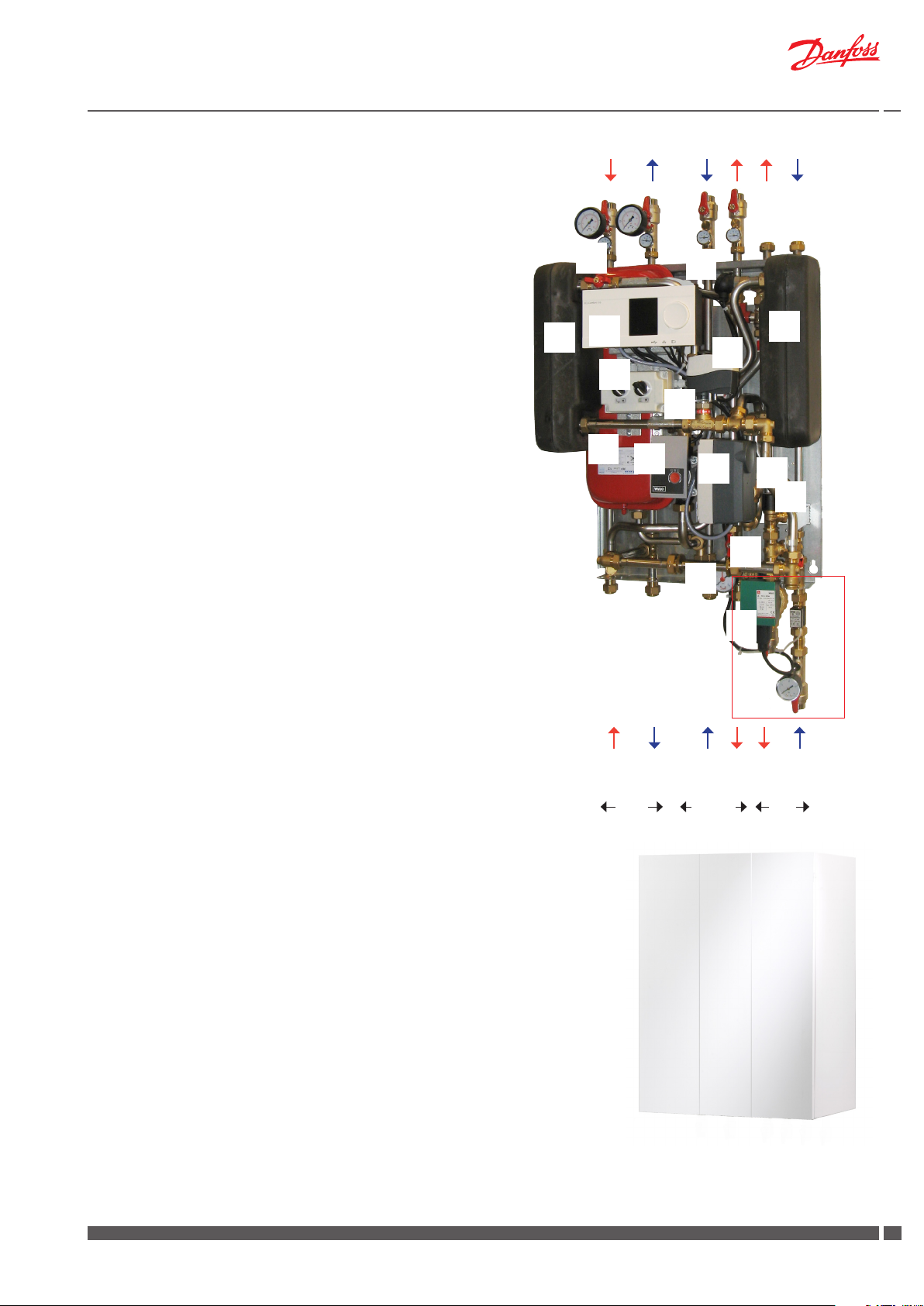
5.1 Akva Lux II VX2
DHW
Circ.
DCW
DH
Supply
DH
Return
Bypass
1 Plate heat exchanger, HE, with insulation
2 Plate heat exchanger, DHW, with insulation
5 Strainer
6 Non-return valve
7 Ball valve
8 Circulation pump HE
11 Safety valve, HE 2,5 bar
12 Safety valve, DHW 10 bar
13 Thermometer
14 Pocket for pressure gauge
15 Manometer
16 Expansion vessel 12 L
17 Air valve
22 Safety thermostat Danfoss AT
23 Sensor pocket for heat meter ½“
24 Fitting piece for heat meter, 1” x 130 mm
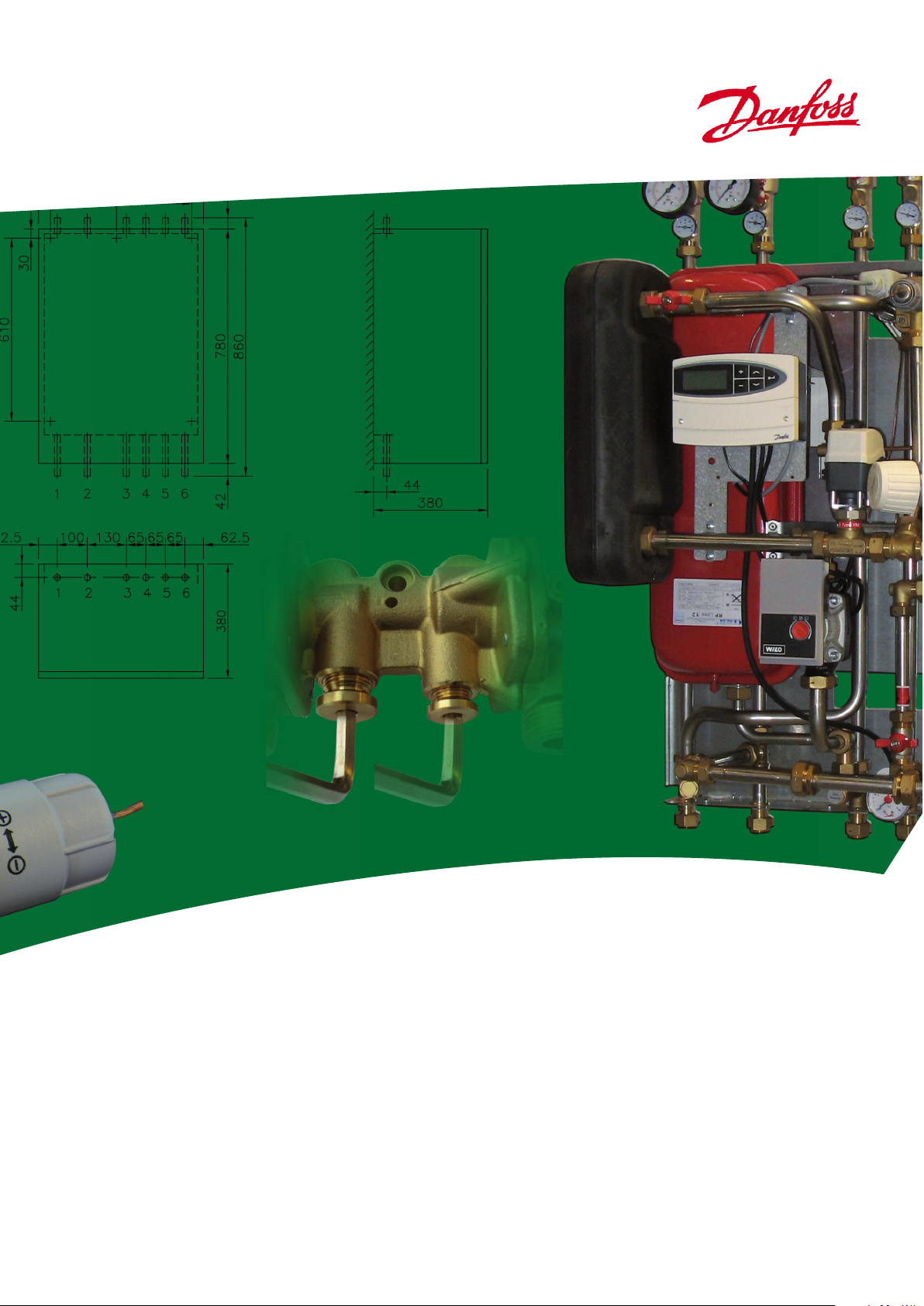
Measurements:
HE
Return
HE
Supply
25 Controller Danfoss ECL 110/A130
26 Outdoor sensor Danfoss ESMT
27 Sensor Danfoss ESMC
29 Danfoss actuator AMV 150
30 2-way valve VS2
38 Domestic hot water controller
Danfoss PTC2 +P
40 Danfoss FJVR for bypass/circulation
--------------------------------------------------------------62 Non-return valve (not part of dly)
64 Circulation pump (not part of dly)
Please note that the unit does not include strainer on DH supply.
It is the responsibility of the energy supplier to secure that a strainer,
mesh 0.6 mm, is tted on the primary side.
Dimensions without cover
H730 x W530 x D360 mm
Dimensions with cover
H780 x W550 x D380 mm
Connections:
Order:
1 District heating (DH) supply
2 District heating (DH) return
4 Heating (HE) return
5 Heating (HE) supply
6 Domestic hot water (DHW)
7 Domestic cold water (DCW)
wall
Connection sizes:
DH: G¾ (ET)
HE: G¾ (ET)
DHW, DCW: G¾ (ET)
top view
4
DKDHR VI.GP.V2.02 Danfoss District Energy
Circ.: G¾” (IT )
Instructions Akva Lux II VX
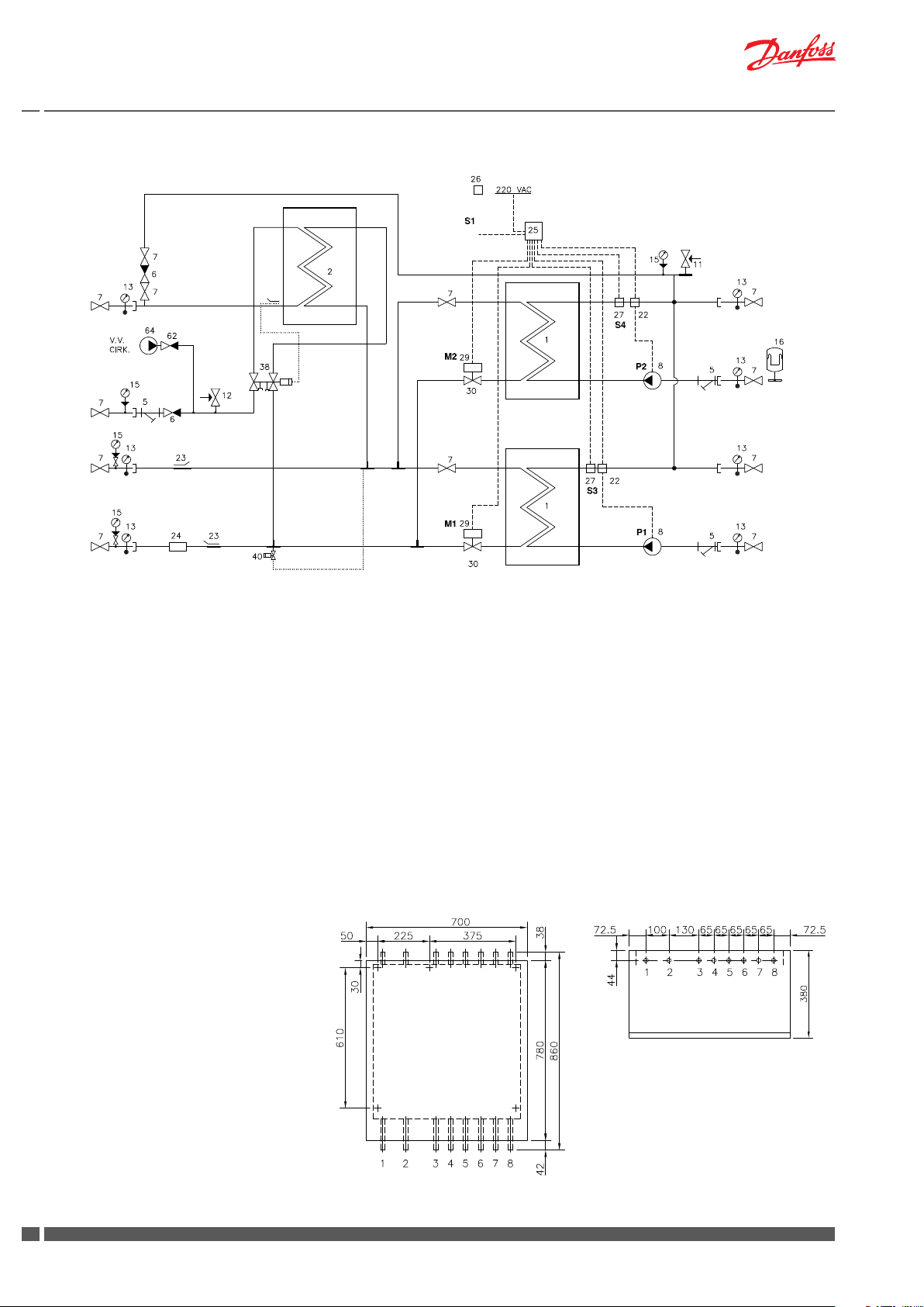
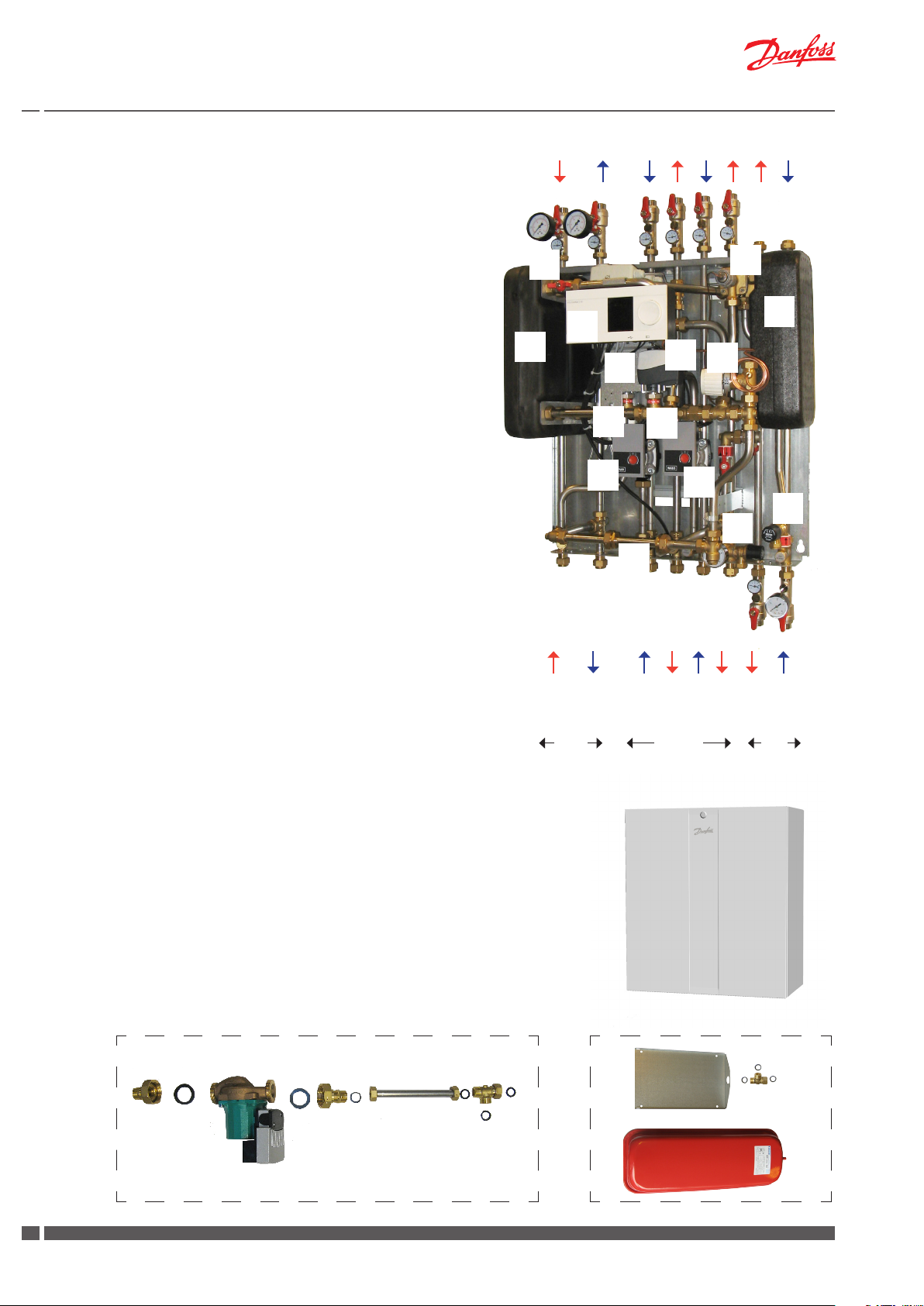
5.2 Akva Lux II VX2-E
DHW
Circ.
DCW
DH
Supply
DH
Return
1 Plate heat exchanger, HE, with insulation
2 Plate heat exchanger, DHW , with insulation
5 Strainer
6 Non-return valve
7 Ball valve
8 Circulation pump HE
9 Circulation pump DHW circ.
11 Safety valve, HE 2,5 bar
12 Safety valve, DHW 10 bar
13 Thermometer
14 Pocket for pressure gauge ½”
15 Manometer
16 Expansion vessel 12 L
17 Air valve
20 Switch box for pumps
HE
Return
HE
Supply
21 Flow switch
22 Safety thermostat Danfoss AT
23 Sensor pocket for heat meter ½“
24 Fitting piece for heat meter, 1” x 130 mm
25 Controller Danfoss ECL 310/A266
26 Outdoor sensor Danfoss ESMT
27 Sensor Danfoss ESMC
29 Danfoss actuator AMV 150
30 2-way valve VS2
31 Danfoss actuator AMV 30
32 2-way valve VM 2
Please note that the unit does not include strainer on DH supply.
It is the responsibility of the energy supplier to secure that a strainer,
mesh 0.6 mm, is tted on the primary side.
Measurements:
Dimensions without cover
H870 x W530 x D360 mm
Dimensions with cover
H870 x W595 x D380 mm
Connections:
Order:
1 District heating (DH) supply
2 District heating (DH) return
4 Heating (HE) return
5 Heating (HE) supply
6 Domestic hot water (DHW)
7 Domestic cold water (DCW)
wall
Connection sizes:
DH: G¾ (ET)
HE: G¾ (ET)
DHW, DCW: G¾ (ET)
top view
Circ.: G¾” (IT )
Danfoss District Energy VI.GP.V2.02 DKDHR
55
Instructions Akva Lux II VX
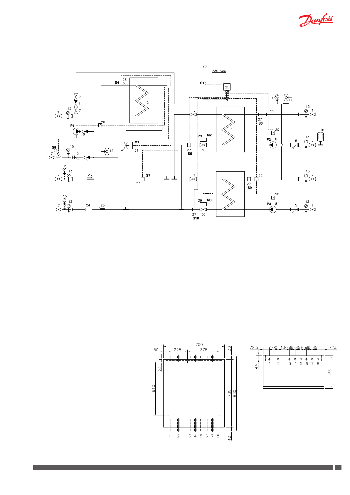
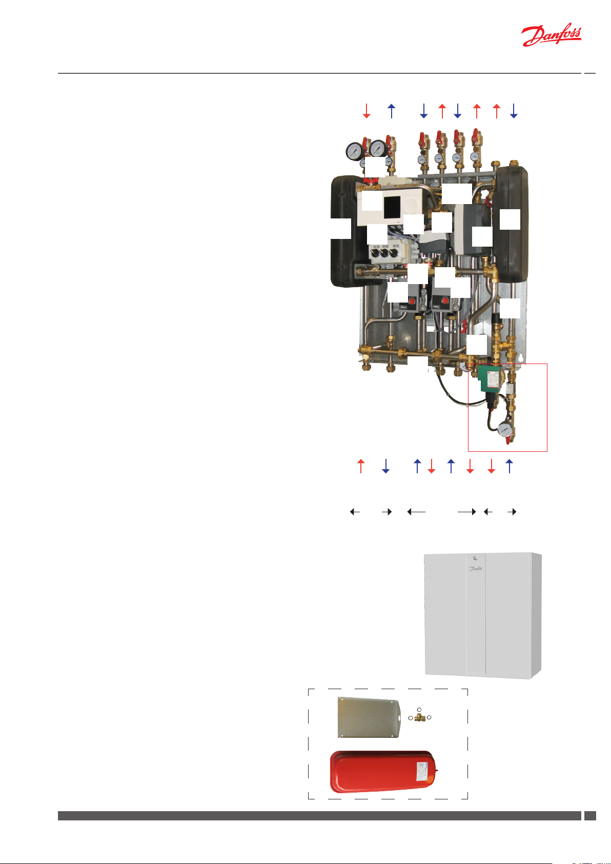
5.3 Akva Lux II VX3
DHW
Circ.
DCW
DH
Supply
DH
Return
Bypass
1 Plate heat exchanger, HE, with insulation
2 Plate heat exchanger, DHW, with insulation
5 Strainer
6 Non-return valve
7 Ball valve
8 Circulation pump HE
11 Safety valve, HE 2,5 bar
12 Safety valve, DHW 10 bar
13 Thermometer
14 Pocket for pressure gauge ½”
15 Manometer
17 Air valve
22 Safety thermostat Danfoss AT
23 Sensor pocket for heat meter ½“
24 Fitting piece for heat meter, 1” x 130 mm
25 Controller Danfoss ECL 310/A260
HE
Return
HE
Supply
HE
Return
HE
Supply
26 Outdoor sensor Danfoss ESMT
27 Sensor Danfoss ESMC
29 Danfoss actuator AMV 150
30 2-way valve VS2
38 Domestic hot water controller
Danfoss PTC2 +P
40 Danfoss FJVR for bypass/circulation
--------------------------------------------------------------16 Expansion vessel 12 L
62 Non-return valve (not part of dly)
64 Circulation pump (not part of dly)
Please note that the unit does not include strainer on DH supply.
It is the responsibility of the energy supplier to secure that a strainer,
mesh 0.6 mm, is tted on the primary side.
Measurements:
Dimensions without cover
H860 x W660 x D360 mm
Dimensions with cover
H860 x W700 x D380 mm
top view
Connections:
Order:
1 District heating (DH) supply
2 District heating (DH) return
3 Heating (HE) return
4 Heating (HE) supply
Connection sizes:
DH: G¾ (ET)
HE: G¾ (ET)
DHW, DCW: G¾ (ET)
Circ.: G¾” (IT )
5 Heating (HE) return
6 Heating (HE) supply
7 Domestic hot water (DHW)
8 Domestic cold water (DCW)
6
DKDHR VI.GP.V2.02 Danfoss District Energy
Instructions Akva Lux II VX
5.4 Akva Lux II VX3-E
DHW
Circ.
DCW
DH
Supply
DH
Return
1 Plate heat exchanger, HE, with insulation
2 Plate heat exchanger, DHW, with insulation
5 Strainer
6 Non-return valve
7 Ball valve
8 Circulation pump HE
9 Circulation pump DHW circ.
11 Safety valve, HE 2,5 bar
12 Safety valve, DHW 10 bar
13 Thermometer
14 Pocket for pressure gauge ½”
15 Manometer
17 Air valve
20 Switch box for pumps
21 Flow switch
22 Safety thermostat Danfoss AT
23 Sensor pocket for heat meter ½“
HE
Supply
HE
Return
HE
Supply
HE
Return
24 Fitting piece for heat meter, 1” x 130 mm
25 Controller Danfoss ECL 310/A376
26 Outdoor sensor Danfoss ESMT
27 Sensor Danfoss ESMC
29 Danfoss actuator AMV 150
30 2-way valve VS2
31 Danfoss actuator AMV 30
32 2-way valve VM2
--------------------------------------------------------------16 Expansion vessel 12 L incl. brackets and T-piece
(supplied loose)
Please note that the unit does not include strainer on DH supply.
It is the responsibility of the energy supplier to secure that a strainer,
mesh 0.6 mm, is tted on the primary side.
Measurements:
Dimensions without cover
H870 x W660 x D360 mm
Dimensions with cover
H870 x W700 x D380 mm
Connections:
top view
Order:
1 District heating (DH) supply
2 District heating (DH) return
3 Heating (HE) return
4 Heating (HE) supply
5 Heating (HE) return
6 Heating (HE) supply
Connection sizes:
DH: G¾ (ET)
HE: G¾ (ET)
DHW, DCW: G¾ (ET)
Circ.: G¾” (IT )
7 Domestic hot water (DHW)
8 Domestic cold water (DCW)
Danfoss District Energy VI.GP.V2.02 DKDHR
77
Instructions Akva Lux II VX
6.0 Main components
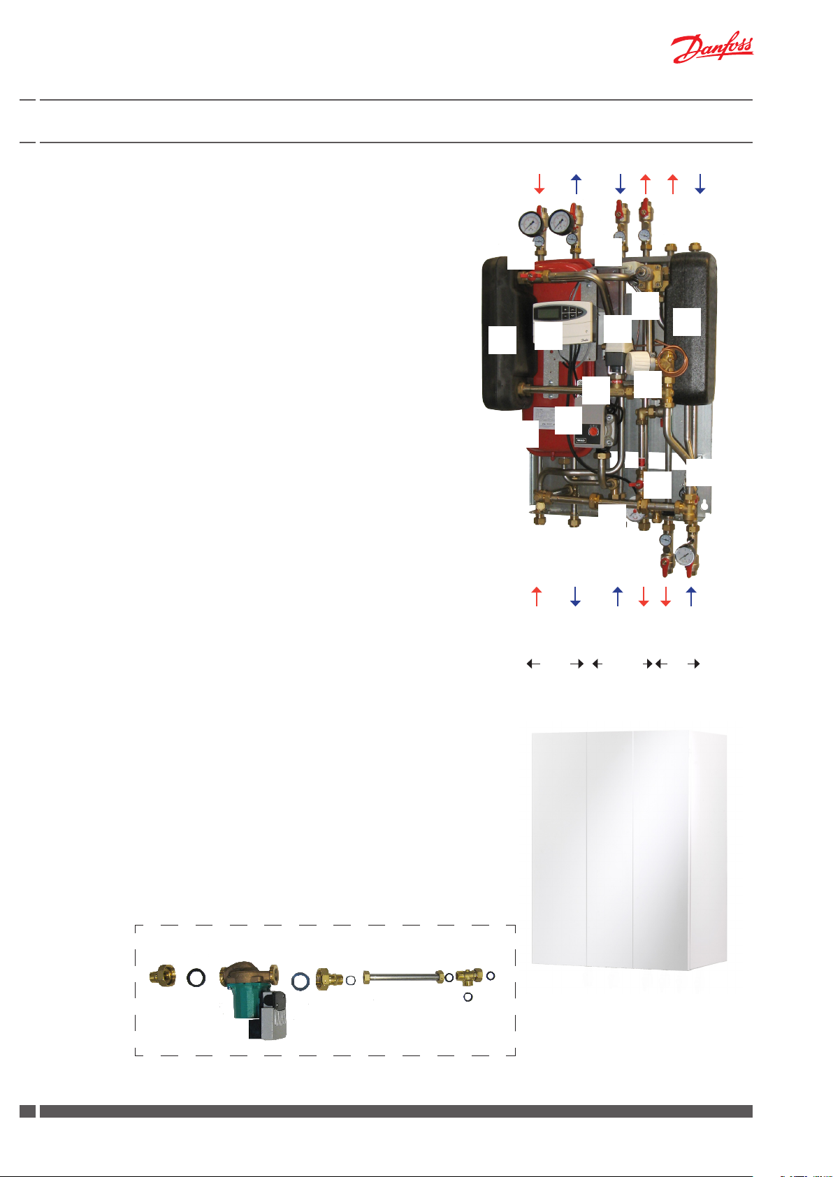
6.1 Akva Lux II VX2
1 Plate heat exchanger HE
2 Plate heat exchanger DHW
8 Pump, HE
11 Safety valve HE
12 Safety vale DHW
16 Expansion vessel
17 Air valve
22 Safety thermostat
24 Fitting piece for heat meter
25 Electronic controller ECL110
29 Actuator AMV 150
30 2-way valve VS 2
38 PTC2+P controller
40 Danfoss thermostat for bypass/circulation
The substations oer variable connection possibilities, as connection of pipes can be established both in the top or in the
bottom of the substation.
17
22
38
2
30
29
40
25
1
8
16
Please note:
Your substation may look dierent than the substation shown, as variants with other components may be supplied. The control function,
however, is basically as stated in this instruction manual.
Instructions for the tted components will be supplied together with
the substation.
Accessories to be ordered separately (mounting on site):
Circulation set - Art. No. 810.441
For systems with DHW circulation.
White-lacquered steel-sheet cover
Art. No. 936.0811
DH supply
Primary
11
12
24
DCW
DHW
DH return
HE return
Secondary
HE supply
DHW
810.441
936.0811
8
DKDHR VI.GP.V2.02 Danfoss District Energy
Instructions Akva Lux II VX
6.2 Akva Lux II VX2-E
1 Plate heat exchanger HE
2 Plate heat exchanger DHW
8 Pump HE
9 Circulation pump, DHW circ.
11 Safety valve HE
12 Safety vale DHW
16 Expansion vessel
17 Air valve
20 Switch box for pumps
21 Flowswitch
22 Safety thermostat
24 Fitting piece for heat meter
25 Electronic controller EC310/A266
29 Actuator AMV 150
30 2-way valve VS 2
31 Actuator AMV 30
32 2-way valve VM2
The substations oer variable connection possibilities, as connection of pipes can be established both in the top or in the
bottom of the substation.
17
25
1
22
2
29
20
30
16
8
31
32
12
Please note:
Your substation may look dierent than the substation shown, as variants with other components may be supplied. The control function,
however, is basically as stated in this instruction manual.
Instructions for the tted components will be supplied together with
the substation.
Accessories, which are supplied loose with the substation
(mounting on site):
Circulation set - Art.No. 810.443
The circulation set is supplied assembled and electrically wired
and ready to mount on the substation as shown on the above
photo.
Accessories to be ordered separately (mounting on site):
White-lacquered steel-sheet cover
Art. No. 936.0811
DH supply
Primary
24
DH return
Secondary DHW
HE return
11
9
HE supply
DHW
21
Circulation set
DCW
936.0811
Danfoss District Energy VI.GP.V2.02 DKDHR
99
Instructions Akva Lux II VX
6.3 Akva Lux II VX3
1 Plate heat exchanger HE
2 Plate heat exchanger DHW
8 Pump, HE
11 Safety valve HE
12 Safety valve DHW
17 Air valve
22 Safety thermostat
24 Fitting piece for heat meter
25 Electronic controller ECL 310/260
29 Actuator AMV 150
30 2-way valve VS2
38 PTC2+P controller
40 Danfoss thermostat for bypass/circulation
The substations oer variable connection possibilities, as
connection of pipes can be established both in the top or in
the bottom of the substation.
22
17
38
2
25
1
29
30
30
29
40
Please note:
Your substation may look dierent than the substation shown, as
variants with other components may be supplied. The control function, however, is basically as stated in this instruction manual.
Instructions for the tted components will be supplied together with
Accessories, which are supplied loose with the substation
(mounting on site):
Expansion vessel - Art. No. RES. 178
Accessories to be ordered separately (mounting on site):
Circulation set - Art. No. 810.441
For systems with DHW circulation.
White-lacquered steel-sheet cover
Art. No. 936.1541
8
24
DH return
DH supply
Primary Secondary
HE return
936.1541
HE supply
8
12
11
DCW
DHW
HE return
HE upply
DHW
810.441
10
DKDHR VI.GP.V2.02 Danfoss District Energy
RES.178
Instructions Akva Lux II VX
6.4 Akva Lux II VX3-E
1 Plate heat exchanger HE
2 Plate heat exchanger DHW
8 Pump, HE
9 Circulation pump, DHW circ.
11 Safety valve HE
12 Safety vale DHW
17 Air valve
19 Connection for di. pressure controller
20 Switch box for pumps
22 Safety thermostat
21 Flowswitch
24 Fitting piece for heat meter
25 Electronic controller ECL 310/A376
29 Actuator AMV 150
30 2-way valve VS2
31 Actuator AMV 30
32 2-way valve VM2
The substations oer variable connection possibilities, as
connection of pipes can be established both in the top or in
the bottom of the substation.
17
25
1
20
22
31
29
29
2
32
30
30
8
8
12
11
Please note:
Your substation may look dierent than the substation shown, as
variants with other components may be supplied. The control function, however, is basically as stated in this instruction manual.
Instructions for the tted components will be supplied together with
the substation.
Accessories, which are supplied loose with the substation
(mounting on site):
Expansion vessel - Res. 178
Circulation set - Art.No. 810.443
The circulation set is supplied assembled and electrically wired
and ready to mount on the substation as shown on the above
photo.
Accessories to be ordered separately (mounting on site):
White-lacquered steel-sheet cover
Art. No. 936.1541
RES.178
24
DH return
DH supply
Primary Secondary
HE return
HE supply
936.1541
9
HE return
HE supply
DHW
DHW
21
Circulation set
DCW
Danfoss District Energy VI.GP.V2.02 DKDHR
1111

Instructions Akva Lux II VX
7.0 Getting started
Connect the substation to the household piping in accordance with
the labelling at the bottom and in accordance with the instructions
in this manual.
If the system features DHW recirculation, a recirculation connection
must be established on the substation.
For instructions about recirculation connection, see page 14.
We recommend establishing recirculation BEFORE mounting the
substation on the wall.
Start-up
1. The ball valves are supplied loose with the substation. Mount the
ball valves for DH supply and return as well as the ball valves for
HE supply and return in the top of the substation. Mount the ball
valves for DHW and DCW in the bottom of the substation.
2. Please note that change of connection from bottom to top
for DCW and DHW includes relocation of blind plates BEFORE
mounting the substation on the wall. (See page 13, item 8.1
for further information.
14. Check the substation and the household piping carefully for any
leaks
15. Pressure test the entire system for leaks in accordance with the
applicable regulations.
16. Connect pump(s) and automatic components to the electricity
supply, but do not switch on the power.
3. The substations are for wall mounting, and the mounting sheet
has got holes for installation. Fix the substation on a solid wall
with two sturdy bolts, screws, expansion bolts or the like.
Please note that we recommend min. two people to lift the
substation.
4. Close all shut-o valves at the substation before connecting
them to the household piping.
5. Mount expansion vessel on substation types Akva Lux II VX3 and
Akva Lux II VX3-E, - see page 16.
6. Mount heat meter, - see page 17.
7. IMPORTANT! Tighten all connections, as vibrations during transport and handling may have caused leaks.
CAUTION! Please note that the connections may be supplied
with EPDM rubber gaskets. Therefore take care not to over-
strain the union nuts, as this may result in leaks. The manufacturer accepts no liability for leaks that result from overstrain
of union nuts.
8. On systems that feature a safety valve, establish a drain connection in compliance with the applicable legislation.
9. Set temperature for AT safety thermostat for oor or radiator heating.
10. If the household piping system features domestic hot water
recirculation, the substation must be connected to the recirculation system. See page 14 for more information about DHW
recirculation.
11. Carefully open the ball valves for the HE supply and return ow as
well as the ball valve for DCW. Carefully open the ll valve and ll
the system with water and at the same time vent the system. Fill
the heat exchanger / the system with water until the manometer shows a working pressure, which correspondes to the system
height + 5 m (approx. 1.2 - 1.5 bar), - see page 18.
17. Heat the system and vent the radiator circuit/heating side
thoroughly on the radiators and the air valve, if any.
18. Switch on the pumps and automatic components.
19. Finish by adjusting the substation in accordance with this
instruction manuals.
IMPORTANT! Heating and cooling of the system may cause
leaks. Therefore it may be necessary to retighten the connections in the period after commissioning.
Check list!
1. Remove plug, if DCW connection is established in
top.
2. Remove plug, if DHW connection is established in
top.
3. Set AT thermostat for oor or radiator heating.
4. Adjust the bypass valve.
5. Connect outdoor temperature sensor to the ECL
controller. (ECL 110, terminals 1 and 2), (ECL 310,
terminals 29 and 30).
6. Adjust controller’s min/max. temperature and
heating curve, - for oor or radiator heating.
12. Close the ll valve.
13. Subsequently open the ball valve for the DH supply and return
ow and heat up the system.
12
DKDHR VI.GP.V2.02 Danfoss District Energy
Instructions Akva Lux II VX
8.0 Mounting
The installation, connection and maintenance of the substation must
be performed by qualied and authorised personnel.
Installation must always be performed in accordance with the applicable legislation and in compliance with these instructions.
The substation must be installed so that it is freely accessible and can
be maintained without unnecessary disruption. Lift the substation
by its mounting plate/rear section and secure it to a solid wall using
2 sturdy bolts, screws or expansion bolts positioned in the two keyholes in the mounting plate/rear section.
Before commissioning, rinse all the pipes in the household piping
system thoroughly to remove any impurities, and check and clean
the dirt strainers in the substation.
Connect the substation to the household piping in accordance with
the labelling at the bottom and/or in accordance with the instructions in this manual.
8.1 Variable connection possibilities
The substations oer variable connection possibilities, as connection of pipes can be established in the top or in the bottom of the
substation.
Upon delivery the ball valves are supplied loose with the substation
and the substation is prepared for mounting of the ball valves for DH
supply and return as well as the ball valves for HE supply and return in
top of the substation and for mounting of the ball valves for DHW and
DCW in the bottom of the substation, as illustrated on the photo to your
right (g. B).
For substations, on which the ball valves are mounted according to
the above, it is possible to change the connection order as follows:
Fig. A
Fig. B
DCW
pipe
DHW
pipe
For change of connection from top to bottom for DH supply and return
and HE supply and return, demount plugs on connection pipes in bottom
of substation and ball valves on connection pipes in top of substations
and mount plugs in connection pipes in top of substation and ball valves
on connection pipes in bottom of substation.
For change of connection from bottom to top for DHW and DCW
please follow the below instructions:
Fig. 1: Demount plugs on connection pipes in top of substation
Fig. 2: Demount ball valves on connection pipes in bottom of
substation
Fig. 3: Relocate blind plate in T-piece on DHW pipe as shown on
photo to your right. Please note the easy access to the T-piece
through a cut out in the back plate.
Fig. 4: Demount blind plate on DCW pipe
Fig. 5: Mount ball valves on DCW and DHW connection pipes in top of
substation.
Fig. 6: Mount plugs in DCW and DHW connection pipes in bottom of
substation
Please note Akva Lux II VX3-E is supplied with blind plate on
the DCW pipe only.
Fig. 1 Fig. 2
Fig. 3 Fig. 4
Fig. 5 Fig. 6
Danfoss District Energy VI.GP.V2.02 DKDHR
1313
Instructions Akva Lux II VX
8.2 DHW recirculation Akva Lux II VX2 & Akva Lux II VX3
If the household plumbing system includes hot water recirculation
the substation must be connected to the hot water recirculation
system by using this circulation set.
It is to be recommended to prepare the substation for recirculation
BEFORE mounting it on the wall.
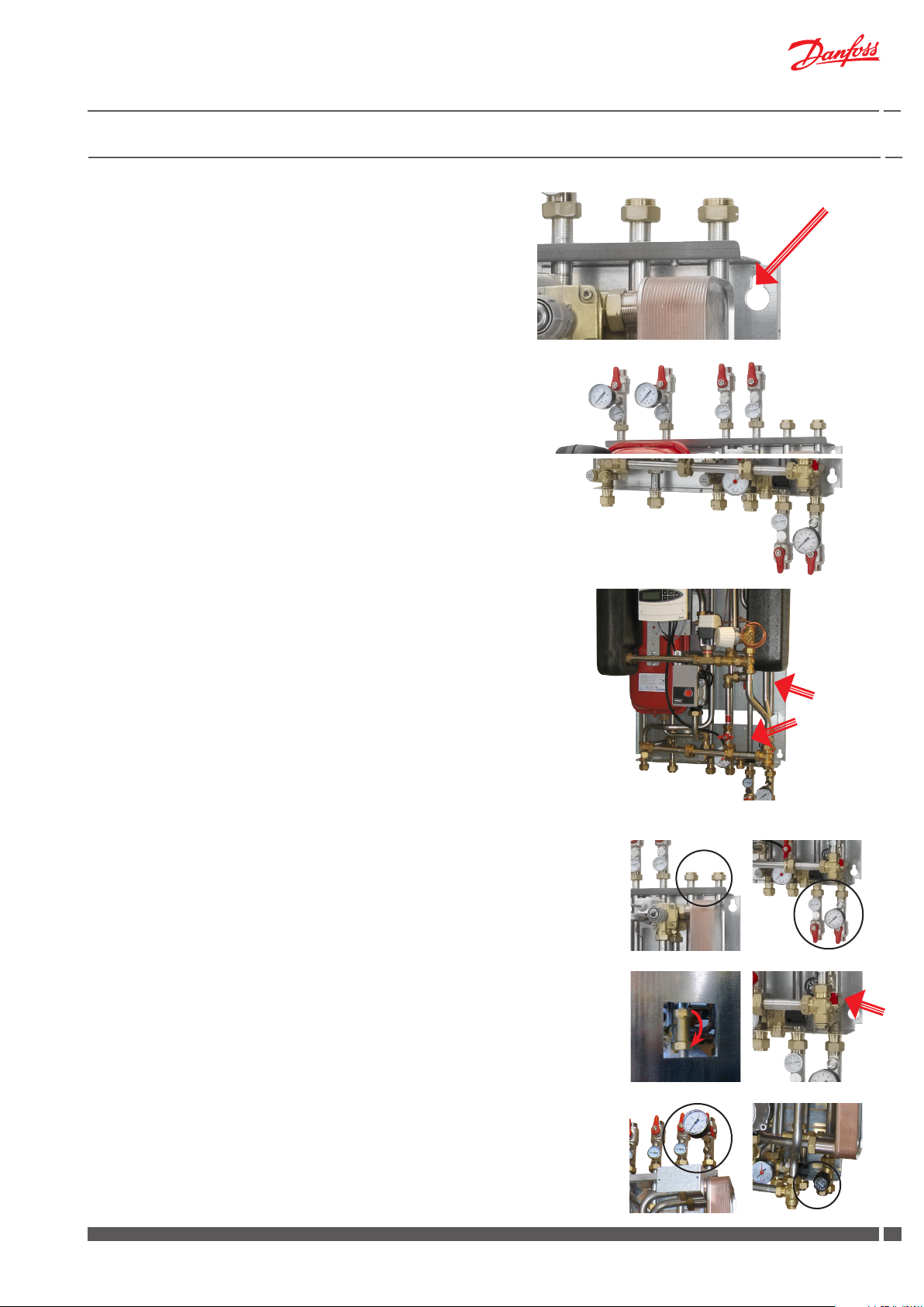
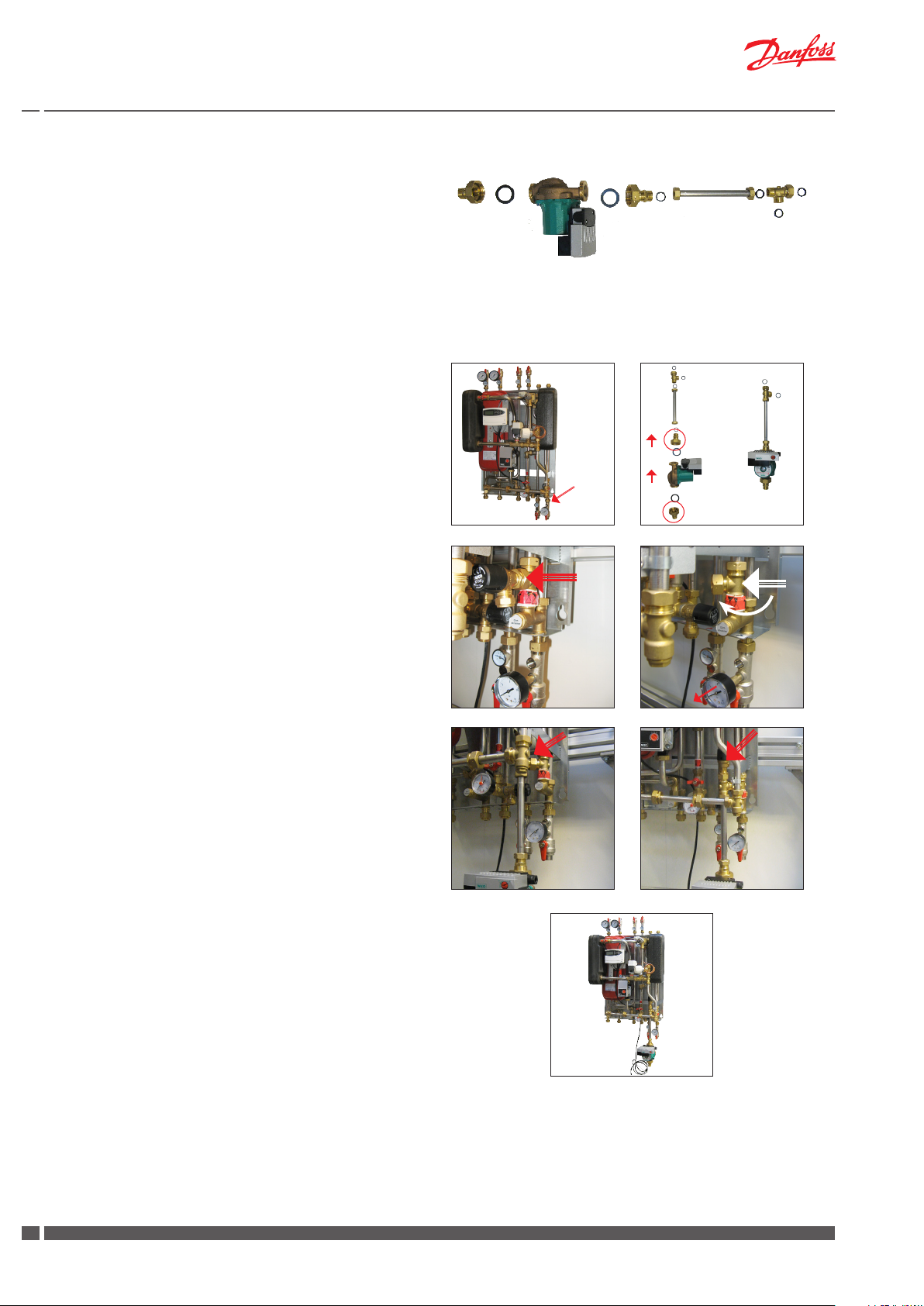
8.2.1 Mounting of circulation set for Akva Lux II VX2 & VX3
Fig. 1. Mount the circulation set on the DCW inlet pipe in the bot-
tom of the substation. The pump must be installed so that
the pump is pumping water towards the substation.
Fig. 2. The circulation set is supplied loose, as illustrated in g. 2a.
Assemble the circulation set as illustrated in g. 2b, and remember to use packing yarn when packing the hexagon
nipple/non-return valve in the 5/4” pump union piece and
make sure that the arrow on the hexagon nipple/non-return
valve points upwards.
Fig. 3. Demount the safety valve (to be reused).
Fig. 4. Turn the T-piece 45°, as illustrated in g. 4.
Fig. 5. Fit the circulation set to the T-piece.
Fig. 6. Remount safety valve on circulation set.
Connect the pump to the household electrical wiring. For
setting and venting of pump, please refer to page 33.
Pack
Pack
Fig. 1 Fig. 2a Fig. 2b
Fig. 3 Fig. 4
Fig. 5 Fig. 6
Akva Lux II VX2 with circulation set
8.2.2 Mounting of circulation set Akva Lux II VX2-E and VX3-E
The circulation set is supplied assembled and electrically wired
and ready to be mounted on the DCW inlet pipe in the bottom of
the substation before start up. See photo on page 9 and 11.
14
DKDHR VI.GP.V2.02 Danfoss District Energy

Instructions Akva Lux II VX
8.3 Safety thermostat
Safety thermostat
The heating circuit is supplied with a safety thermostat, type AT
pipe thermostat, for protection against overheating. The AT thermostat is mounted directly on the pipe with a steel band.
The AT pipe thermostat is used to regulate the medium temperature in the pipe, on which the thermostat is mounted. AT senses the
temperature in the pipe through its contact surface and is therefore
suitable to control the ow temperature, as it - in combination with
the ECL controller - switches of the pump to prevent excessive levels of temperature.
Please see enclosed operating instructions
Thermostat type AT
Data Sheet
Thermostat type AT
Application
Technical Data
Accessories
Danfoss Heating Solutions VDGIA102 © Danfoss 01/2012 1
The AT thermostat can be mounted on the pipe
The AT pipe thermostat is used to regulate the
without emptying the plant of water.
medium temperature in the pipe on which the
thermostat is mounted. AT senses the temperature in the pipe through its contact surface and is
therefore suitable to control boiler or flow temperature in central heating systems.
The AT pipe thermostat comprises a bimetallaic
sensor, a contact system and a setting knob.
On connection to terminals CO and NC the thermostat breaks on a rise in temperature.
On connection to terminals CO and NO the thermostat close on a rise in temperature.
Temperature range 30 to 90 °C
Temperature scale external (type 041E0000)
internal (type 041E0020)
Temperature differential 8 K
Max. temperature plant surface Ts90
Max. ambient temperature 55 °C
Storage temperature -20 to 90 °C
Switch system SPDT
Enclosure IP40
Terminal CO-NC Breaks on temperature rise
Terminal CO-NO Closes on temperature rise
Switch load 6 (2.5) A, 250 Vac
0.1 A, 250 Vdc
Approval according to EMC Standard EN 60730-2-9: 1995
EMC Standard Emission EN 55014
Environment Normal
Installation Installed in any position
Product Code no.
Heat-conductive compound ~ 5 g 041E0110
Heat-conductive compound ~ 1 kg 041E0111
If the supply water temperature rises above the thermostat set
point (for oor heating 50 °C, for radiator heating 80 °C) the heat
pump stops.
The pump starts again as the temperature drops about 6 °C below
the thermostat set point.
Note!
The thermostat set point is changed as follows:
1. Pull the thermostat on the surface of the pipe until it is easily
accessible (g. 1).
2. Demount the thermostat cover cap (g. 2).
3. Turn the spindle to set a new value. Turn the indicator and set
the value according to the embossed thermostat scale on the
thermostat base plate. Scale 30-90 ° C (g. 3).
4. Finally, mount the cover cap and slide the thermostat back in
place.
Remove
Set temperature
80 °C
50 °C
Fig. 1
Fig. 2
Note!
Temperature range for the safety thermostat is 30 - 90 °C.
The temperature is not preset from factory.
For oor heating the value must be set to max. 50 °C.
In case of radiator heating the value must be set to 80 °C.
Fig. 3
Danfoss District Energy VI.GP.V2.02 DKDHR
1515

8.4 Expansion vessel
Expansion vessel, Akva Lux II VX2 and VX2-E
The Akva Lux II VX2 substation is equipped with an expansion vessel, which is factory set to 0.5 bar.
Expansion vessel, Akva Lux II VX3 and VX3-E
An expansion vessel is supplied loose with the Akva Lux II VX3
substations for mounting on site.
The expansion vessel is factory set to 0.5 bar.
The expansion vessel can be connected to the substation either
in the top or in the bottom of the substation, - oppositely to the
pipes connection, which can be established both in the top or in
the bottom of the substation.
Mount the expansion vessel according to the below instructions:
1. Mount the T-piece on the HE supply either in top or bottom of
substation.
2. Mount the bracket on the wall.
3. Place the expansion vessel on the bracket and fasten it with
union nuts or screw nuts (not part of the delivery).
4. Establish pipe connection between T-piece and connecting
piece on expansion vessel. (Please note that a connection
pipe is not part of the delivery).
Expansion vessel
T-piece
Bracket
16
DKDHR VI.GP.V2.02 Danfoss District Energy

Instructions Akva Lux II VX
8.5 Heat meter, Fitting piece
The substations are equipped with tting pieces for heat meter on
the district heating return line.
Fitting of heat meter
- Close the ball valves on the district heating and the heating
sides.
- Loosen the union nuts at both ends of the tting piece and
remove it.
- Fit the heat meter, - remember to insert gaskets.
- Mount sensor, - remember to insert gaskets.
- After mounting of heat meter remember to check and tighten
all pipe connections before commissioning the heat meter.
8.6 Test and connections
Before lling the system with water, retighten all the pipe connections
because vibrations and shocks during transport and handling may
have caused leaks. Once the system has been lled with water, tighten
all the pipe connections once more before performing pressure test
for leaks. After heating of the system, check all the connections and
retighten if necessary.
Please note that the connections may feature EPDM rubber gaskets!
Therefore, it is important that you DO NOT OVERTIGHTEN the
union nuts. Over-tightening may result in leaks. Leaks caused by
over-tightening or failure to retighten connections are not covered
by the warranty.
8.7 Mounting of outdoor temperature sensor
The outdoor temperature sensor is delivered separately and must be
mounted on site according to the enclosed illustrations.
The outdoor sensor is always to be mounted on the coldest side of
the property (normally the north side of the property).
The sensor must not be exposed to the morning sun, and should not
be mounted above windows, doors, air vents or other heat sources,
and not under balconies and roof eaves.
Mounting height approx. 2.5 m above ground.
Temperature range: -50 to 50° C
Electrical connections
Two wire non polarized (can be crossed)
Sensor cable: 2 x 0.4 - 1.5 mm²
ECL 110:
Connect the cable ends to ECL controller in clamps 1 and 2.
ECL 310
Connect the cable ends to ECL controller in clamps 29 and 30.
8.8 Safety valves
A discharge outlet from the safety valves must be established in compliance with local regulations.
Danfoss District Energy VI.GP.V2.02 DKDHR
1717

9.0 Filling, Start-up
Prior to the Akva Lux II VX installation all its pipes and connections
should be cleaned and rinsed. After that the dirt strainers should
be cleaned.
Due to vibrations during transport all connections must be checked
and tightened before lling and start-up.
Before lling up the system and rst start-up, check if:
- pipes are connected according to the circuit diagram,
- expansion vessel is connected,
- heat meter is mounted,
- shut-o valves are closed,
- threaded and anged connections are tightened.
Filling:
The lling valve(s) are used for lling up the heating circuit.
• The pump must be switched o when lling the system with
water.
• Open the ball valves for the HE supply and return ow as well
as the ball valve for DCW.
• Carefully open the ll valve(s) and ll the system with water
and at the same time vent the system.
Filling valves
Akva Lux II VX2
Filling valves
Akva Lux II VX3
Filling valves
Akva Lux II VX2-E
Filling valves
Akva Lux II VX3-E
• Fill heat exchanger / the system with water until the manometer shows a working pressure, which corresponds to the
system height + 5 m (approx. 1.2 - 1.5 bar).
• Close the ll valve(s).
• Then open the ball valves for the DH supply and return ow
and heat up the system.
• After lling and heat- up of the system, it should be vented by
means of the air vents on the substation and on the radiators.
• Then switch on the pump(s).
10.0 Manometer and relling
If the pressure drops below 1 bar, water must be added to the
system. The operating pressure should never exceed 1.5 bar.
(The safety valves open at 2.5 bar)
If the system pressure drops dramatically within a short time, or
if you experience that it is necessary often to rell the system,
the heating system should be examined for leaks, - this includes
checking the factory set pressure of the expansion vessel.
18
DKDHR VI.GP.V2.02 Danfoss District Energy

11.0 Electrical connections
The station is wired and tested in the factory.
Electrical connections between the controller, pump(s), sensor
and actuator(s) are made.
The electrical connection of the substation must be performed
by a qualied and authorised electrician in compliance with all
applicable rules and regulations.
The station should be connected to a 230 V AC power supply.
The power supply connection must be carried out in accordance
with the applicable regulations and instructions.
The station must be wired and connected to an external main
switch so that it can be turned o during maintenance, cleaning
or repair work or in case of an emergency situation.
Component Supply voltage
Controller
ECL 110
Controller
ECL 310
Actuator
AMV 150
Actuator
AMV10/20/30
Pump, Wilo Yonos
Para
Pump, Wilo
Star Z Nova
Pump, Wilo Stratos
Eco Z
230 V a.c., 50 Hz 3 VA
230 V a.c., 50 Hz 5 VA
230 V a.c., 60 Hz 8 VA
230 V a.c., 60 Hz 2 VA
230 V a.c., 50 Hz Max. 45 Watt
230 V a.c., 50 Hz Max. 4.5 Watt
230 V a.c., 50 Hz Max. 59 Watt
Power
consumption
Danfoss District Energy VI.GP.V2.02 DKDHR
1919

Instructions Akva Lux II VX2
12.0 Description of Akva Lux II VX variants
12.1 Akva Lux II VX2 (ECL 110)
Substation for indirect heating for single-family, semi-detatched and
terraced houses as well as ats. With one heating circuit for radiator or
oor heating and instantaneous domestic hot water heater. Designed
for wall-mounting with connections in top and bottom of substation.
The temperature for the heating circuit is controlled by a Danfoss
ECL 110 controller in combination with an electronic actuator. The
supply temperature is calculated by the controller on basis of the
outdoor temperature.
Please note:
Your substation may look dierent than the substation shown, as variants with other components may be supplied.
Instructions for the tted components will always be supplied together with the substation.
Heating circuit
The temperature for the heating circuit is controlled electronically
by the Danfoss ECL controller. The supply temperature is calculated
by the controller on basis of the outdoor temperature.
The factory-setting of the controller ensures that heating is automatically switched o in the summer period.
In periods with higher heat demand the controller settings can be
changed in accordance with the enclosed producer instructions for
the mounted controller.
Installation & Maintenance
Danfoss ECL Comfort 110
Instructions
ECL Comfort 110
Application 116
Constant temperature control
of domestic hot-water systems (DHW)
$2!&4
DH-SMT/DK VI.KT.F2.02 © Danfoss 06/2008
User guide,
Installation & Maintenance
Control of heating circuit
For controlling the heating circuit the Akva Lux II VX 2 (ECL 110) is
supplied with a 2-way valve VS 2 and an electrical actuator AMV 150,
which in combination with the ECL controller controls the heating
circuit.
The electrical actuator has undergone a functional test from factory.
In case of operating disturbances the actuator can be closed manually turning the manual override knob on top of actuator counterclockwise.
Please see enclosed instructions,
Electrical actuator AMV 150
2-way valve VS 2
INSTRUCTIONS
VS2 2-way
065R9075
Instructions
AMV 150
065R9075
Manual override (AMV 150)
AMV 150 + AMV 150 + AMV 150 +
VS2 (DN 15) VMV AVQM (DN 15)
Actuators for three point control AMV 150 www.danfoss.com Page 2
ENGLISH
Motorer til 3-punkts styring AMV 150 www.danfoss.dk Side 3
DANSK
Stellantriebe für 3-Pkt.- Eingangssignal AMV 150 www.danfoss.de Seite 3
DEUTSCH
Motor för 3-punktsreglering AMV 150 varme.danfoss.se Sida 4
SVENSKA
Servomotor met 3-puntssturing AMV 150 www.danfoss.nl Pagina 4
NEDERLANDS
Pavaros trijų padėčių valdymui AMV 150 www.danfoss.lt 5 puslapis
LIETUVIŲ K.
Motori trīs punktu kontrolei AMV 150 www.danfoss.com Lpp. 5
LATVISKI
Szelepmozgatók hárompontos szabályozáshoz AMV 150 www.danfoss.com 6. oldal
DN L (mm)
15 65
20 70
25 75
DN L1(mm)
15 131
20 142
25 159
DN L2(mm)
15 139
20 154
25 159
7369267-9 SIBC R&D EI.97.Q2.00© Danfoss 12/01 1
20
DKDHR VI.GP.V2.02 Danfoss District Energy
MAGYAR
Servopohony s tříbodovým regulačním signálem AMV 150 www.danfoss.cz Strana 6
ČESKY
Siłowniki sterowane sygnałem 3-punktowym AMV 150 www.danfoss.pl Strona 7
POLSKI
Электроприводы для трехпозиционного регулирования AMV 150
РУССКИЙ
DN L3(mm)
15 69
20 74
25 79
www.danfoss.ru Страница 7
VS 2
Press and hold the button (on
the bottom side of the actuator)
during manual override.

Instructions Akva Lux II VX2
Circulation pump, heating circuit
See chapter 13 on page 32 for more information about circulation
pump.
Safety thermostat
The heating circuit is supplied with a safety thermostat, type AT
pipe thermostat, for protection against overheating.
The AT pipe thermostat is used to regulate the medium temperature in the pipe, on which the thermostat is mounted. AT senses the
temperature in the pipe through its contact surface and is therefore
suitable to control the ow temperature, as it - in combination with
the ECL controller - switches of the pump to prevent excessive levels of temperature.
Please see enclosed operating instructions
Thermostat type AT
Note!
Temperature range for the safety thermostat is 30 - 90 °C.
The temperature is not preset from factory.
Data Sheet
Thermostat type AT
Application
Technical Data
Accessories
The AT thermostat can be mounted on the pipe
The AT pipe thermostat is used to regulate the
without emptying the plant of water.
medium temperature in the pipe on which the
thermostat is mounted. AT senses the temperature in the pipe through its contact surface and is
therefore suitable to control boiler or flow temperature in central heating systems.
The AT pipe thermostat comprises a bimetallaic
sensor, a contact system and a setting knob.
On connection to terminals CO and NC the thermostat breaks on a rise in temperature.
On connection to terminals CO and NO the thermostat close on a rise in temperature.
Temperature range 30 to 90 °C
Temperature scale external (type 041E0000)
Temperature differential 8 K
Max. temperature plant surface Ts90
Max. ambient temperature 55 °C
Storage temperature -20 to 90 °C
Switch system SPDT
Enclosure IP40
Terminal CO-NC Breaks on temperature rise
Terminal CO-NO Closes on temperature rise
Switch load 6 (2.5) A, 250 Vac
Approval according to EMC Standard EN 60730-2-9: 1995
EMC Standard Emission EN 55014
Environment Normal
Installation Installed in any position
Product Code no.
Heat-conductive compound ~ 5 g 041E0110
Heat-conductive compound ~ 1 kg 041E0111
internal (type 041E0020)
0.1 A, 250 Vdc
Remove
Set temperature
80 °C
50 °C
For oor heating the value must be set to max. 50 °C.
In case of radiator heating the value must be set to 80 °C.
Domestic hot water
The domestic hot water is prepared in a heat exchanger based on the
ow principle and the temperature is controlled by a combined hydraulic
and thermostatic self-acting controller PTC2+P with integrated dierential pressure controller, which blocks the ow of primary and secondary
side ow through the heat exchanger immediately after completion of
the tapping process.
DHW temperature control
Danfoss PTC2+P controller (1) for DHW. The DHW temperature is adjusted
by turning the lever towards “+” (warmer) or “-” (colder).
Start by turning the handle clockwise - until stop /until the handle can
not be turned anymore. Then turn the handle counter-clockwise until
the temperature of the tap water is approx. 48° C at normal use (7-8 l/
min). The temperature should never exceed 55° C to avoid lime scale
precipitation.
Bypass thermostat
Bypass thermostat (default).
As a standard the Akva Lux II VX2 is equipped with a bypass thermostat,
Danfoss FJVR (2), which ensures that hot water is produced immediately, when tapping starts. It is recommended to set the thermostat
in pos.3. If the water temperature rises too slowly it can be necessary
to set the thermostat at higher value.
Alternatively a DHW circulation system must be installed.
1
Handle for temperature setting
2
Approximate scale settings
2 = 30° C
3 = 40 °C
4 = 45° C
I = 50° C
(max. temperature)
DHW recirculation
For Akva Lux II VX2 switching to recirculation is possible from a
constructional point of view, requiring only an additional circulation set. The circulation set is not included in the delivery and must
be ordered separately and mounted on site.
See instructions for mounting of circulation set on page 14.
You must always t a pump and a non-return valve to the recirculation pipe, with ow direction towards the susbstation.
Danfoss District Energy VI.GP.V2.02 DKDHR
2121

Instructions Akva Lux II VX2-E
12.2 Akva Lux II VX2-E (ECL 310/A266)
Substation for indirect heating for single-family, semi-detatched and
terraced houses as well as ats. With one heating circuit for radiator or
oor heating and instantaneous domestic hot water heater. Designed
for wall-mounting with connections in top and bottom of substation.
The temperature for the heating circuit is controlled by a Danfoss
ECL 310 controller in combination with an electronic actuator. The
supply temperature is calculated by the controller on basis of the
outdoor temperature.
Please note:
Your substation may look dierent than the substation shown, as variants with other components may be supplied.
Instructions for the tted components will always be supplied together with the substation.
Heating circuit
The temperature for the heating circuit is controlled electronically by
the Danfoss ECL controller. The supply temperature ist calculated by
the controller on basis of the outdoor temperature.
The ECL Comfort 310 controller is loaded with a selected application
by means of an ECL Application Key (Plug-&-Play). The Application
Key contains information about application, languages and factory
settings.
The controller is factory preset to turn o the heating automatically
in the summer period.
The controller settings can be changed in accordance with the enclosed producer instructions for the mounted controller.
See ECL Application Key Box with ECL Comfort 210/310 user guide
and mounting guide, for further information.
Control of heating circuit
For control of heating circuit 1 the Akva Lux II VX2-E (ECL 310) is
supplied with a 2-way valve VS 2 and an electrical actuator AMV 150,
which in combination with the ECL controller controls the heating
circuit.
The electrical actuator has undergone a functional test from factory.
In case of operating disturbances the actuator can be closed manually turning the manual override knob on top of actuator counterclockwise.
Please see enclosed instructions,
Electrical actuator AMV 150
2-way valve VS 2
INSTRUCTIONS
VS2 2-way
065R9075
Instructions
AMV 150
065R9075
ECL application key
Manual override (AMV 150)
AMV 150 + AMV 150 + AMV 150 +
VS2 (DN 15) VMV AVQM (DN 15)
Actuators for three point control AMV 150 www.danfoss.com Page 2
ENGLISH
Motorer til 3-punkts styring AMV 150 www.danfoss.dk Side 3
DANSK
Stellantriebe für 3-Pkt.- Eingangssignal AMV 150 www.danfoss.de Seite 3
DEUTSCH
Motor för 3-punktsreglering AMV 150 varme.danfoss.se Sida 4
SVENSKA
Servomotor met 3-puntssturing AMV 150 www.danfoss.nl Pagina 4
NEDERLANDS
Pavaros trijų padėčių valdymui AMV 150 www.danfoss.lt 5 puslapis
LIETUVIŲ K.
Motori trīs punktu kontrolei AMV 150 www.danfoss.com Lpp. 5
LATVISKI
Szelepmozgatók hárompontos szabályozáshoz AMV 150 www.danfoss.com 6. oldal
DN L (mm)
15 65
20 70
25 75
DN L1(mm)
15 131
20 142
25 159
DN L2(mm)
15 139
20 154
25 159
7369267-9 SIBC R&D EI.97.Q2.00 © Danfoss 12/01 1
MAGYAR
Servopohony s tříbodovým regulačním signálem AMV 150 www.danfoss.cz Strana 6
ČESKY
Siłowniki sterowane sygnałem 3-punktowym AMV 150 www.danfoss.pl Strona 7
POLSKI
Электроприводы для трехпозиционного регулирования AMV 150
РУССКИЙ
DN L3(mm)
15 69
20 74
25 79
www.danfoss.ru Страница 7
VS 2
Press and hold the button (on
the bottom side of the actuator)
during manual override.
22
DKDHR VI.GP.V2.02 Danfoss District Energy

Instructions Akva Lux II VX2-E
Circulation pumps, heating circuit
See chapter 13 on page 32 for more information about circulation
pump.
Switch box for pumps
Power switch 1 switches o the DHW/DCW circulation pump.
Power switch 2 switches o the pump for heating circuit 1.
Power switch 3 switches o the pump for heating circuit 2.
Safety thermostat
The heating circuit is supplied with a safety thermostat, type AT
pipe thermostat, for protection against overheating.
The AT pipe thermostat is used to regulate the medium temperature in the pipe, on which the thermostat is mounted. AT senses the
temperature in the pipe through its contact surface and is therefore
suitable to control the ow temperature, as it - in combination with
the ECL controller - switches of the pump to prevent excessive levels of temperature.
Please see enclosed operating instructions
Note!
Thermostat type AT
Temperature range for the safety thermostat is 30 - 90 °C.
The temperature is not preset from factory.
For oor heating the value must be set to max. 50 °C.
In case of radiator heating the value must be set to 80 °C.
Data Sheet
Thermostat type AT
Application
Technical Data
Accessories
The AT thermostat can be mounted on the pipe
The AT pipe thermostat is used to regulate the
without emptying the plant of water.
medium temperature in the pipe on which the
thermostat is mounted. AT senses the temperature in the pipe through its contact surface and is
therefore suitable to control boiler or flow temperature in central heating systems.
The AT pipe thermostat comprises a bimetallaic
sensor, a contact system and a setting knob.
On connection to terminals CO and NC the thermostat breaks on a rise in temperature.
On connection to terminals CO and NO the thermostat close on a rise in temperature.
Temperature range 30 to 90 °C
Temperature scale external (type 041E0000)
internal (type 041E0020)
Temperature differential 8 K
Max. temperature plant surface Ts90
Max. ambient temperature 55 °C
Storage temperature -20 to 90 °C
Switch system SPDT
Enclosure IP40
Terminal CO-NC Breaks on temperature rise
Terminal CO-NO Closes on temperature rise
Switch load 6 (2.5) A, 250 Vac
Approval according to EMC Standard EN 60730-2-9: 1995
EMC Standard Emission EN 55014
Environment Normal
Installation Installed in any position
Product Code no.
Heat-conductive compound ~ 5 g 041E0110
Heat-conductive compound ~ 1 kg 041E0111
0.1 A, 250 Vdc
Remove
1 2 3
Set temperature
80 °C
50 °C
Danfoss District Energy VI.GP.V2.02 DKDHR
2323

Instructions Akva Lux II VX2-E
Domestic hot water
The domestic hot water is prepared in a heat exchanger based on the
ow principle and the temperature is controlled by a two -vay val ve and
an actuator in combination with the ECL controller.
Substations with electronic control of the domestic hot water circuit
are prefabricated with DHW recirculation.
DHW temperature control
For controlling the domestic hot water temperature the Akva Lux
II VX2-E is supplied with 2-way valve VM 2 and an actuator AMV 30,
which in combination with the ECL controller controls the domestic hot water circuit.
The controller closes when set max. ow is exceeded.
The electrical actuator has undergone a functional test from factory.
Please see enclosed instructions,
Electrical actuator AMV 30
2-way valve VM2
Instructions
AMV 20, AMV 30
082R9092
AMV 20, AMV 30 + VM2, VS2 AMV 20, AMV 30 + AVQM AMV 20, AMV 30 + VB2
1
2
3
4
N - 1
N - 3
7369220-2 EI.96.A1.00 © Danfoss 02/02 1
082R9092
065R9074
VM2 VB2
Instructions
VM2, VB2 2-way
DN L (mm)
15 65
20 70
25 75
32 100
40 110
50 130
DN L1(mm)
15 131
20 142
25 159
32 196
40 196
50 228
DN L2(mm)
15 139
20 154
25 159
32 184
40 294
50 330
065R9074
DN L3(mm)
15 69
20 74
25 79
32 104
40 114
50 134
DHW recirculation
Substations with electronic control of the domestic hot water
circuit are prefabricated for DHW recirculation.
The circulation set is supplied assembled, incl. circulation pump
and electrically wired and ready to mount on the substation.
AMV 30
VM2
DHW circulation pump
The Akva Lux II VX2-E substations come standard with a Wilo-Star-Z
NOVA circulation pump, which is electrically connected to the ECL controller from factory.
See chapter 14.2 on page 33 for more information about DHW
pumps.
24
DKDHR VI.GP.V2.02 Danfoss District Energy

Instructions Akva Lux II VX3
12.3 Akva Lux II VX3 (ECL210/A260)
Substation for indirect heating for single-family, semi-detatched
and terraced houses as well as ats. With two heating circuits and
instantaneous domestic water heater. Designed for wall-mounting
with connections in top and bottom of substation.
The temperature for the heating circuits is controlled by a Danfoss ECL
310 controller in combination with electronic actuators. The supply
temperature is calculated by the controller on basis of the outdoor
temperature.
Please note:
Your substation may look dierent than the substation shown, as variants with other components may be supplied.
Instructions for the tted components will always be supplied together with the substation.
Heating circuit
The temperature for the heating circuit is controlled electronically by
the Danfoss ECL controller. The supply temperature ist calculated by
the controller on basis of the outdoor temperature.
The ECL Comfort 310 controller is loaded with a selected application
by means of an ECL Application Key (Plug-&-Play). The Application
Key contains information about application, languages and factory
settings.
The controller is factory preset to turn o the heating automatically
in the summer period.
The controller settings can be changed in accordance with the enclosed producer instructions for the mounted controller.
See ECL Application Key Box with ECL Comfort 210/310 user guide
and mounting guide, for further information.
Control of heating circuit 1
For control of heating circuit 1 the Akva Lux II VX3 (ECL 310) is supplied
with a 2-way valve VS 2 and an electrical actuator AMV 150, which
in combination with the ECL controller controls the heating circuit.
The electrical actuator has undergone a functional test from factory.
In case of operating disturbances the actuator can be closed manually turning the manual override knob on top of actuator counterclockwise.
Please see enclosed instructions,
Electrical actuator AMV 150
2-way valve VS 2
INSTRUCTIONS
VS2 2-way
065R9075
Instructions
AMV 150
065R9075
Manual override (AMV 150)
AMV 150 + AMV 150 + AMV 150 +
VS2 (DN 15) VMV AVQM (DN 15)
Actuators for three point control AMV 150 www.danfoss.com Page 2
ENGLISH
Motorer til 3-punkts styring AMV 150 www.danfoss.dk Side 3
DANSK
Stellantriebe für 3-Pkt.- Eingangssignal AMV 150 www.danfoss.de Seite 3
DEUTSCH
Motor för 3-punktsreglering AMV 150 varme.danfoss.se Sida 4
SVENSKA
Servomotor met 3-puntssturing AMV 150 www.danfoss.nl Pagina 4
NEDERLANDS
Pavaros trijų padėčių valdymui AMV 150 www.danfoss.lt 5 puslapis
LIETUVIŲ K.
Motori trīs punktu kontrolei AMV 150 www.danfoss.com Lpp. 5
LATVISKI
Szelepmozgatók hárompontos szabályozáshoz AMV 150 www.danfoss.com 6. oldal
DN L (mm)
15 65
20 70
25 75
DN L1(mm)
15 131
20 142
25 159
DN L2(mm)
15 139
20 154
25 159
7369267-9 SIBC R&D EI.97.Q2.00 © Danfoss 12/01 1
MAGYAR
Servopohony s tříbodovým regulačním signálem AMV 150 www.danfoss.cz Strana 6
ČESKY
Siłowniki sterowane sygnałem 3-punktowym AMV 150 www.danfoss.pl Strona 7
POLSKI
Электроприводы для трехпозиционного регулирования AMV 150
РУССКИЙ
DN L3(mm)
15 69
20 74
25 79
www.danfoss.ru Страница 7
VS 2
Press and hold the button (on
the bottom side of the actuator)
during manual override.
Danfoss District Energy VI.GP.V2.02 DKDHR
2525

Instructions Akva Lux II VX3
Control of heating circuit 2
For control of heating circuit 2 the Akva Lux II VX3 (ECL 310) is supplied
with a 2-way valve VS 2 and an electrical actuator AMV 150, which
in combination with the ECL controller controls the heating circuit.
The electrical actuator has undergone a functional test from factory.
In case of operating disturbances the actuator can be closed manually turning the manual override knob on top of actuator counterclockwise.
Please see enclosed instructions,
Electrical actuator AMV 150
2-way valve VS 2
INSTRUCTIONS
VS2 2-way
065R9075
DN L (mm)
15 65
20 70
25 75
DN L1(mm)
15 131
20 142
25 159
DN L2(mm)
15 139
20 154
25 159
7369267-9 SIBC R&D EI.97.Q2.00 © Danfoss 12/01 1
Instructions
AMV 150
065R9075
AMV 150 + AMV 150 + AMV 150 +
VS2 (DN 15) VMV AVQM (DN 15)
Actuators for three point control AMV 150 www.danfoss.com Page 2
ENGLISH
Motorer til 3-punkts styring AMV 150 www.danfoss.dk Side 3
DANSK
Stellantriebe für 3-Pkt.- Eingangssignal AMV 150 www.danfoss.de Seite 3
DEUTSCH
Motor för 3-punktsreglering AMV 150 varme.danfoss.se Sida 4
SVENSKA
Servomotor met 3-puntssturing AMV 150 www.danfoss.nl Pagina 4
NEDERLANDS
Pavaros trijų padėčių valdymui AMV 150 www.danfoss.lt 5 puslapis
LIETUVIŲ K.
Motori trīs punktu kontrolei AMV 150 www.danfoss.com Lpp. 5
LATVISKI
Szelepmozgatók hárompontos szabályozáshoz AMV 150 www.danfoss.com 6. oldal
MAGYAR
Servopohony s tříbodovým regulačním signálem AMV 150 www.danfoss.cz Strana 6
ČESKY
Siłowniki sterowane sygnałem 3-punktowym AMV 150 www.danfoss.pl Strona 7
POLSKI
Электроприводы для трехпозиционного регулирования AMV 150
РУССКИЙ
DN L3(mm)
15 69
20 74
25 79
www.danfoss.ru Страница 7
VS 2
Manual override (AMV 150)
Press and hold the button (on
the bottom side of the actuator)
during manual override.
Circulation pumps, heating circuits
See chapter 13 on page 32 for more information about circulation
pumps.
Safety thermostat
The heating circuit is supplied with a safety thermostat, type AT
pipe thermostat, for protection against overheating.
The AT pipe thermostat is used to regulate the medium temperature in the pipe, on which the thermostat is mounted. AT senses
the temperature in the pipe through its contact surface and is
therefore suitable to control the ow temperature, as it - in combination with the ECL controller - switches of the pump to prevent
excessive levels of temperature.
Please see enclosed operating instructions
Thermostat type AT
Data Sheet
Thermostat type AT
Application
Technical Data
Accessories
Danfoss Heating Solutions VDGIA102 © Danfoss 01/2012 1
The AT thermostat can be mounted on the pipe
The AT pipe thermostat is used to regulate the
without emptying the plant of water.
medium temperature in the pipe on which the
thermostat is mounted. AT senses the temperature in the pipe through its contact surface and is
therefore suitable to control boiler or flow temperature in central heating systems.
The AT pipe thermostat comprises a bimetallaic
sensor, a contact system and a setting knob.
On connection to terminals CO and NC the thermostat breaks on a rise in temperature.
On connection to terminals CO and NO the thermostat close on a rise in temperature.
Temperature range 30 to 90 °C
Temperature scale external (type 041E0000)
Temperature differential 8 K
Max. temperature plant surface Ts90
Max. ambient temperature 55 °C
Storage temperature -20 to 90 °C
Switch system SPDT
Enclosure IP40
Terminal CO-NC Breaks on temperature rise
Terminal CO-NO Closes on temperature rise
Switch load 6 (2.5) A, 250 Vac
Approval according to EMC Standard EN 60730-2-9: 1995
EMC Standard Emission EN 55014
Environment Normal
Installation Installed in any position
Product Code no.
Heat-conductive compound ~ 5 g 041E0110
Heat-conductive compound ~ 1 kg 041E0111
internal (type 041E0020)
0.1 A, 250 Vdc
Note!
Temperature range for the safety thermostat is 30 - 90 °C.
The temperature is not preset from factory.
Remove
Set temperature
80 °C
50 °C
For oor heating the value must be set to max. 50 °C.
In case of radiator heating the value must be set to 80 °C.
26
DKDHR VI.GP.V2.02 Danfoss District Energy

Instructions Akva Lux II VX3
Domestic hot water
The domestic hot water is prepared in a heat exchanger based on the
ow principle and the temperature is controlled by a combined hydraulic and thermostatic self-acting controller PTC2+P with integrated
dierential pressure controller, which blocks the ow of primary and
secondary side ow through the heat exchanger immediately after
completion of the tapping process.
DHW temperature control
Danfoss PTC2+P controller (1) for DHW. The DHW temperature is adjusted
by turning the lever towards “+” (warmer) or “-” (colder).
Start by turning the handle clockwise - until stop /until the handle can
not be turned anymore. Then turn the handle counter-clockwise until
the temperature of the tap water is approx. 48° C at normal use (7-8 l/
min). The temperature should never exceed 55° C to avoid lime scale
precipitation.
Bypass or circulation thermostat
Bypass thermostat (default).
As a standard the Akva Lux II VX3 is equipped with a bypass thermostat,
Danfoss FJVR (2), which ensures that hot water is produced immediately, when tapping starts. It is recommended to set the thermostat
in pos.3. If the water temperature rises too slowly it can be necessary
to set the thermostat at higher value.
Alternatively a DHW circulation system must be installed.
DHW recirculation
For Akva Lux II VX3 switching to recirculation is possible from a constructional point of view, requiring only an additional circulation
set.
The circulation set is not included in the delivery and must be ordered separately and mounted on site.
See instructions for mounting of circulation set on page 14.
1
Handle for temperature setting
2
Approximate scale settings
2 = 30° C
3 = 40 °C
4 = 45° C
I = 50° C
(max. temperature)
Remember always to mount circulation pump, non-return valve and
safety valve on the circulation pipe. The pump must be installed so
Danfoss District Energy VI.GP.V2.02 DKDHR
2727

Instructions Akva Lux II VX3-E
12.4 Akva Lux II VX3-E (ECL310/A376)
Substation for indirect heating for single-family, semi-detatched
and terraced houses as well as ats. With two heating circuits and
instantaneous domestic water heater. Designed for wall-mounting
with connections in top and bottom of substation.
The temperature for the heating circuits is controlled by a Danfoss ECL
310 controller in combination with electronic actuators. The supply
temperature is calculated by the controller on basis of the outdoor
temperature.
The domestic hot water temperature is also controlled by the ECL
310 in combination with an electronic actuator.
Please note:
Your substation may look dierent than the substation shown, as variants with other components may be supplied.
Instructions for the tted components will always be supplied together with the substation.
Heating circuit
The temperature for the heating circuit is controlled electronically by
the Danfoss ECL controller. The supply temperature ist calculated by
the controller on basis of the outdoor temperature.
The ECL Comfort 310 controller is loaded with a selected application
by means of an ECL Application Key (Plug-&-Play). The Application
Key contains information about application, languages and factory
settings.
The controller is factory preset to turn o the heating automatically
in the summer period.
The controller settings can be changed in accordance with the enclosed producer instructions for the mounted controller.
See ECL Application Key Box with ECL Comfort 210/310 user guide
and mounting guide, for further information.
We also refer to Danfoss Installation Guide for ECL Comfort 310, application
A376, which can be found on www.heating.danfoss.com
Switch box for pumps
Power switch 1 switches o the DHW/DCW circulation pump.
Power switch 2 switches o the pump for heating circuit 1.
Power switch 3 switches o the pump for heating circuit 2.
ECL application key
1
2 3
28
DKDHR VI.GP.V2.02 Danfoss District Energy

Instructions Akva Lux II VX3-E
Control of heating circuit 1
For controlling the heating circuit 1 the Akva Lux II VX3-E is supplied
with a 2-way valve VS 2 and an electrical actuator AMV 150, which
in combination with the ECL controller controls the heating circuit.
The electrical actuator has undergone a functional test from factory.
In case of operating disturbances the actuator can be closed manually turning the manual override knob on top of actuator counterclockwise.
Please see enclosed instructions,
Electrical actuator AMV 150
2-way valve VS 2
INSTRUCTIONS
VS2 2-way
065R9075
DN L (mm)
15 65
20 70
25 75
DN L1(mm)
15 131
20 142
25 159
DN L2(mm)
15 139
20 154
25 159
Instructions
AMV 150
065R9075
AMV 150 + AMV 150 + AMV 150 +
VS2 (DN 15) VMV AVQM (DN 15)
Actuators for three point control AMV 150 www.danfoss.com Page 2
ENGLISH
Motorer til 3-punkts styring AMV 150 www.danfoss.dk Side 3
DANSK
Stellantriebe für 3-Pkt.- Eingangssignal AMV 150 www.danfoss.de Seite 3
DEUTSCH
Motor för 3-punktsreglering AMV 150 varme.danfoss.se Sida 4
SVENSKA
Servomotor met 3-puntssturing AMV 150 www.danfoss.nl Pagina 4
NEDERLANDS
Pavaros trijų padėčių valdymui AMV 150 www.danfoss.lt 5 puslapis
LIETUVIŲ K.
Motori trīs punktu kontrolei AMV 150 www.danfoss.com Lpp. 5
LATVISKI
Szelepmozgatók hárompontos szabályozáshoz AMV 150 www.danfoss.com 6. oldal
MAGYAR
Servopohony s tříbodovým regulačním signálem AMV 150 www.danfoss.cz Strana 6
ČESKY
Siłowniki sterowane sygnałem 3-punktowym AMV 150 www.danfoss.pl Strona 7
POLSKI
Электроприводы для трехпозиционного регулирования AMV 150
РУССКИЙ
DN L3(mm)
15 69
20 74
25 79
www.danfoss.ru Страница 7
Manual override (AMV 150)
VS 2
Press and hold the button (on
the bottom side of the actuator)
during manual override.
Control of heating circuit 2
For controlling the heating circuit 2 the Akva Lux II VX3-E is supplied
with a 2-way valve VS 2 and an electrical actuator AMV 150, which
in combination with the ECL controller controls the heating circuit.
The electrical actuator has undergone a functional test from factory.
In case of operating disturbances the actuator can be closed manually turning the manual override knob on top of actuator counterclockwise.
Please see enclosed instructions,
Electrical actuator AMV 150
2-way valve VS 2
INSTRUCTIONS
VS2 2-way
065R9075
DN L (mm)
15 65
20 70
25 75
DN L1(mm)
15 131
20 142
25 159
DN L2(mm)
15 139
20 154
25 159
7369267-9 SIBC R&D
Instructions
AMV 150
065R9075
AMV 150 + AMV 150 + AMV 150 +
VS2 (DN 15) VMV AVQM (DN 15)
Actuators for three point control AMV 150 www.danfoss.com Page 2
ENGLISH
Motorer til 3-punkts styring AMV 150 www.danfoss.dk Side 3
DANSK
Stellantriebe für 3-Pkt.- Eingangssignal AMV 150 www.danfoss.de Seite 3
DEUTSCH
Motor för 3-punktsreglering AMV 150 varme.danfoss.se Sida 4
SVENSKA
Servomotor met 3-puntssturing AMV 150 www.danfoss.nl Pagina 4
NEDERLANDS
Pavaros trijų padėčių valdymui AMV 150 www.danfoss.lt 5 puslapis
LIETUVIŲ K.
Motori trīs punktu kontrolei AMV 150 www.danfoss.com Lpp. 5
LATVISKI
Szelepmozgatók hárompontos szabályozáshoz AMV 150 www.danfoss.com 6. oldal
MAGYAR
Servopohony s tříbodovým regulačním signálem AMV 150 www.danfoss.cz Strana 6
ČESKY
Siłowniki sterowane sygnałem 3-punktowym AMV 150 www.danfoss.pl Strona 7
POLSKI
Электроприводы для трехпозиционного регулирования AMV 150
РУССКИЙ
DN L3(mm)
15 69
20 74
25 79
www.danfoss.ru Страница 7
Manual override (AMV 150)
VS 2
Press and hold the button (on
the bottom side of the actuator)
during manual override.
Danfoss District Energy VI.GP.V2.02 DKDHR
2929

Instructions Akva Lux II VX3-E
Circulation pumps, heating circuits
See chapter 13 on page 32 for more information about circulation
pumps.
Safety thermostat
The heating circuit is supplied with a safety thermostat, type AT
pipe thermostat, for protection against overheating.
The AT pipe thermostat is used to regulate the medium temperature in the pipe, on which the thermostat is mounted. AT senses
the temperature in the pipe through its contact surface and is
therefore suitable to control the ow temperature, as it - in combination with the ECL controller - switches of the pump to prevent
excessive levels of temperature.
Please see enclosed operating instructions
Thermostat type AT
Data Sheet
Thermostat type AT
Application
Technical Data
Accessories
Danfoss Heating Solutions VDGIA102 © Danfoss 01/2012 1
The AT thermostat can be mounted on the pipe
The AT pipe thermostat is used to regulate the
without emptying the plant of water.
medium temperature in the pipe on which the
thermostat is mounted. AT senses the temperature in the pipe through its contact surface and is
therefore suitable to control boiler or flow temperature in central heating systems.
The AT pipe thermostat comprises a bimetallaic
sensor, a contact system and a setting knob.
On connection to terminals CO and NC the thermostat breaks on a rise in temperature.
On connection to terminals CO and NO the thermostat close on a rise in temperature.
Temperature range 30 to 90 °C
Temperature scale external (type 041E0000)
Temperature differential 8 K
Max. temperature plant surface Ts90
Max. ambient temperature 55 °C
Storage temperature -20 to 90 °C
Switch system SPDT
Enclosure IP40
Terminal CO-NC Breaks on temperature rise
Terminal CO-NO Closes on temperature rise
Switch load 6 (2.5) A, 250 Vac
Approval according to EMC Standard EN 60730-2-9: 1995
EMC Standard Emission EN 55014
Environment Normal
Installation Installed in any position
Product Code no.
Heat-conductive compound ~ 5 g 041E0110
Heat-conductive compound ~ 1 kg 041E0111
internal (type 041E0020)
0.1 A, 250 Vdc
Note!
Temperature range for the safety thermostat is 30 - 90 °C.
The temperature is not preset from factory.
For oor heating the value must be set to max. 50 °C.
In case of radiator heating the value must be set to 80 °C.
Remove
Set temperature
80 °C
50 °C
30
DKDHR VI.GP.V2.02 Danfoss District Energy

Domestic hot water
The domestic hot water is prepared in a heat exchanger based on the
ow principle and the temperature is controlled by a two -vay val ve and
an actuator in combination with the ECL controller.
Substations with electronic control of the domestic hot water circuit
are prefabricated with DHW recirculation.
DHW temperature control
For controlling the domestic hot water temperature the Akva Lux
II VX3-E is supplied with 2-way valve VM 2 and an actuator AMV 30,
which in combination with the ECL controller controls the domestic hot water circuit.
The controller closes when set max. ow is exceeded.
The electrical actuator has undergone a functional test from factory.
Please see enclosed instructions,
Electrical actuator AMV 30
2-way valve VM2
Instructions
AMV 20, AMV 30
082R9092
AMV 20, AMV 30 + VM2, VS2 AMV 20, AMV 30 + AVQM AMV 20, AMV 30 + VB2
1
2
3
4
N - 1
N - 3
7369220-2 EI.96.A1.00 © Danfoss 02/02 1
082R9092
065R9074
VM2 VB2
Instructions
VM2, VB2 2-way
DN L (mm)
15 65
20 70
25 75
32 100
40 110
50 130
DN L1(mm)
15 131
20 142
25 159
32 196
40 196
50 228
DN L2(mm)
15 139
20 154
25 159
32 184
40 294
50 330
065R9074
DN L3(mm)
15 69
20 74
25 79
32 104
40 114
50 134
AMV 30
VM2
Danfoss District Energy VI.GP.V2.02 DKDHR
3131

Instructions Akva Lux II VXInstructions Akva Lux II VX
DHW recirculation
Substations with electronic control of the domestic hot water
circuit are prefabricated for DHW recirculation.
The circulation set is supplied assembled, incl. circulation pump
and electrically wired and ready to mount on the substation.
DHW circulation pump
The Akva Lux II VX3-E substations come standard with a Wilo-Star-Z
NOVA circulation pump, which is electrically connected to the ECL controller from factory.
See chapter 14.2 on page 33 for more information about DHW
pumps.
13.0 Circulation pumps - Heating
The Akva Lux II VX2 and VX3 substations come standard with Wilo circulation pump Wilo Yonos Para. If another pump type is used the Wilo
installation and operating instructions will be replaced by the installation and operating instructions for the pump in question.
Substation start-up / setting of pump
The pump is operated using the red operating knob. In turning the
knob the dierent control modes can be selected.
In a traditional radiator system the red operating knob must be set in
the left side control mode (1).
In oor heating systems and old radiator systems with large pipes and
radiators the red button must be set in the right side control mode (2).
Hereafter the pressure decreases to t the building’s heating needs, - in
due consideration of cooling and power consumption.
Venting: The pumps have a built-in venting function, which can be
used when the system must be vented. To vent the system turn the
red button to select the symbol for air venting (middle position) (3),
after which the pumps run a venting routine of 10 minutes duration.
There may be noise during the air venting routine. When the 10 min.
has passed the pumps must be set according to the above instructions.
For more information please refer to enclosed installation and operating instructions:
Wilo Yonos Para
Installation and operating instructions
1 2 3
1 General
About this document
Wilo-Yonos PARA
The new standard in High Efficiency
GB:Installation and operating instructions Wilo-Yonos PARA
Installation and operating instructions Wilo-Yonos PARA 02/12 4523676-01
32
DKDHR VI.GP.V2.02 Danfoss District Energy
The language of the original operating instructions is English. All
other languages of these instructions are translations of theoriginal
operating instructions.These installation and operating instructions
are an integral part of the product. They must be kept readily
available at the place where the product is installed. Strict
adherence to theseinstructions is a precondition for the proper use
and correctoperation of the product.
The installation and operating instructions correspond to the
relevant version of the product and the underlying safety regulations
and standards valid at the time of going to print.EC declaration of
conformity:
A copy of the EC declaration of conformity is a component ofthese
operating instructions(f ig 8). If a technical modification is made on
the designs named therewithout our agreement or the declarations
made in the installation and operating instructions on
product/personnel safety
are not observed, this declaration loses its validity.
2 Safety
These operating instructions contain basic information which must
be adhered to during installation, operation and maintenance.
For this reason, these operating instructions must, without fail, be
read by the service technician and the responsible
specialist/operator before installation and operation.
It is not only the general safety instructions listed under the main
point “safety” that must be adhered to but also the special safety
instructions with danger symbols included under the following main
points.
Wilo Yonos Para

Instructions Akva Lux II VX
14.0 Circulation pumps - Domestic hot water
14.1 Wilo-Stratos ECO-Z (Circulation set 810.441)
The circulation set for Akva Lux II VX2 and Akva Lux II VX3 comes standard with Wilo-Star-Z 20-4 circulation pump.
Substation start-up / setting of pump
Ensure that the pipe system is properly lled and air vented (automatically venting).
In due consideration of the system and operating characteristics preselect the pump capacity at the red dial button to 1.5 m.
If the heating capacity proves insucient increase heat setting step by
step
Reduce head setting step by step if the heating capacity is too high or
noise generation is excessive.
For information about manual venting of pump etc. please refer to enclosed installation and operating instructions:
Wilo-Stratos ECO-Z
Installation and operating instructions
Wilo-Stratos ECO
GB Installation and operating instructions
F Notice de montage et de mise en service
NL Inbouw- en bedieningsvoorschriften
E
I
P
TR Montaj ve kullanma klavuzu
GR Οδηγίες εγκατάστασης και λειτουργίας
H Beépítési és üzemeltetési utasítás
PL Instrukcja montażu i obsługi
4 131 020-Ed. 02 / 2010-06-Wilo
Instrucciones de instalación y funcionamiento
Istruzioni di montaggio, uso e manutenzione
Manual de instalação e funcionamento
CZ Návod kmontáži a obsluze
RUSИнструкция по монтажу и эксплуатации
EST Paigaldus- ja kasutusjuhend
LV
Uzstādīšanas un ekspluatācijas instrukcija
LT Montavimo ir naudojimo instrukcija
SK Návod na montáž a obsluhu
SLO Navodila za vgradnjo in obratovanje
RO Instrucţiuni de montaj şi exploatare
BG Инструкция за монтаж и експлоатация
14.2 Wilo-Star-Z NOVA (Circulation set 810.443)
The Akva Lux II VX3-E and VX2-E come standard with a Wilo-Star-Z
NOVA circulation pump
Substation start-up / setting of pump
The pump is electrically connected to the ECL controller from factory,
and needs no start-up adjustment.
For information about venting of pump etc. please refer to enclosed
installation and operating instructions:
Wilo-Star-Z NOVA,
Installation and operating instructions
Wilo-Star-Z NOVA
F Notice de montage et de mise en service
FIN Asennus- ja käyttöohje
S Monterings- och skötselanvisning
DK Monterings- og driftsvejledning
4 142 347-Ed.03/2010-02
Danfoss District Energy VI.GP.V2.02 DKDHR
3333

Instructions Akva Lux II VX
15.0 Maintenance
Maintenance work
Is only to be carried out by qualied and authorised personnel.
Inspection
The water heater should be checked regularly by authorised personnel. Any necessary maintenance must be performed in accordance
with the instructions in this manual and other sets of instructions.
During service the dirt strainers are to be cleaned – including the lter on the
controller, all pipe connections must be tightened and the safety valve must be
function tested by turning the lever.
Rinsing/cleaning of plate heat exchanger
To clean the plate heat exchanger, rinse it by running clean water through the
exchanger at high speed and in the opposite direction to the normal ow. This
will remove any dirt deposits that may have built up in the exchanger. If rinsing
with clean water is not sucient, the exchanger can also be cleaned by circulating
a cleaning agent approved by Danfoss (e.g. Radiner Fl cleaning uid) through the
exchanger. Both these cleaning uids are environmentally friendly and can be
disposed o through the standard sewer system. After use of a cleaning uid, the
plate heat exchanger must be rinsed thoroughly with clean water.
Acid cleaning of plate heat exchanger
Deposits of limescale may build up in plate heat exchangers for domestic hot water
on account of the large temperature uctuations, and because aerated water is
used on the secondary side. If it becomes necessary to clean the exchanger with
acid, this can be done as shown on the drawing to the right. Brazed plate heat
exchangers can withstand rinsing with a dilute acid sulution - e.g. 5% formic, acetic
or phosphoric acid).
Measures after maintenance work
After maintenance work and before commissioning:
– Check that all screwed connections are tight.
– Check that all safety features, covers, that were removed, have been replaced
properly.
– Clean the working area and remove any spilled materials.
– Clear all tools, materials and other equipment from the working area.
– Connect to energy supply and check for leaks.
– Vent the system.
– Carry out any necessary adjustment again.
– Make sure that all safety features on the device and the system work properly.
Meter reading
The caretaker/owner must perform visual checking and reading of the district
heating meter at short, regular intervals. (The meter is not a part of the delivery
from Danfoss). Service procedures must only be performed by trained, authorised
personnel.
NB! Excessive consumption for whatever reason is not covered by the Danfoss
warranty.
Cooling / Return temperature reading
Cooling – i.e. the dierence between the supply and return temperature
of the district heating water – has a signicant eect on overall energy economy.
Therefore, it is important to focus on the supply and return temperature in the
heating system. The dierence should typically be 30–35°C. Please note that a low
district heating return temperature is directly related to the return temperature from
the heating circuit and the return temperature of the circulation water.
It is therefore important to focus on these return temperatures.
Tightening of connections
When reading the heat meter, all ttings and connections should be checked for
leaks. If leaks are detected, contact qualied and authorized personnel immediately.
Please note that the connections may be supplied with EPDM rubber gaskets.
Therefore take care not to overstrain the union nuts, as this may result in
leaks. The manufacturer accepts no liability for leaks that result from overstrain
of union nuts.
34
DKDHR VI.GP.V2.02 Danfoss District Energy

Instructions Akva Lux II VX
15.1 Maintenance plan (recommendations)
Interval Maintenance work Comments
Check all connections for leakages In case of leakages replace gaskets and tighten connections.
Check the functions of the safety valve on the DCW inlet pipe
General visual check of all components for damage and
functions
Clean all lters and strainers in the substation Replace the lters and strainers if the are damaged.
Every 12 months
Check the functions of electric and electronic components,
switches etc.
Check pipes and heat exchangers for corrosion Visual control
Check the functions of the insulation cover Check that the insulation cover ts closely to the product
Check that the temperature controllers are set according to
the instructions in this instruction manual
Check the functions of all shut-o valves Open and close shut-o valves
Work on the device may be carried out only by qualied, specially
trained personnel.
NOTE! After maintenance work has been carried out, ALL gaskets
should be replaced.
After having added water to the system, tighten all the connections
before performing leak test.
Check the connections and tighten if necessary after heat up of the
system.
Please note that the connections may be supplied with EPDM rubber
gaskets! Therefore take care not to overstrain the union nuts, as
this may result in leaks. The manufacturer accepts no liability for
leaks that result from overstrain of union nuts.
Check the functions of the safety valves by turning the valve head of the
safety valve
In case of obvious damage or irregularities check the functions of the
component and replace if necessary
Visual control. Make sure that manual switching on and o is possible.
Follow the instructions in this instruction manual
Danfoss District Energy VI.GP.V2.02 DKDHR
3535

Instructions Akva Lux II VX
16.0 Troubleshooting
If operating disturbances occur, the following basic features
should be checked before carrying out acual troubleshooting:
- the substation is correctly,
- the district heating supply temperature is at the normal level
(summer at least 60 °C, winter at least 70 °C),
16.1 Troubleshooting - Heating
Problem Possible cause Solution
Strainer clogged on DH og HE side
(radiator circuit).
Filter in district heating meter clogged. Clean the lter (after consulting the
Defective dierential pressure controller.
(if any)
Defective sensor Replace sensor
Defektive actuator. Check the functioning of the actuator.
Defective motor valve - or possibly dirt
in the valve housing.
No heat
Automatic controls wrongly set or defective - possibly power failure.
- the dierential pressure is higher than or equal to the normal
(local) dierential pessure in the district heating network. - If
in doubt, ask the district heating plant,
- the substation is connected to electricity (pump and
automatic,
- the dirt strainer in the district heating supply pipe is clean,
- air pockets in the system.
Clean strainer.
district heating plant).
Check the functions of the dierential
pressure controller - clean valve seat if
required.
Check the functions of the motor valve clean valve housing if required.
Check if the setting of the controller is
correct - see separate instructions. Check
the power supply.
Temporary setting of actuator to “manual” control - see instruction on heating
circuit, manual control.
Uneven heat distribution
Supply temperature too high
Pump out of operation.
The pump is set at too low speed of
rotation.
Air pockets in the system. Vent the installation thoroughly.
Air pockets in the system. Vent the installation thoroughly.
Wrong setting of automatic controls. Adjust automatic controls, see instruc-
Defective sensor. Replace sensor.
Defective controller. The controller does
not react as it is should in accordance
with the instructions.
Check that the pump is receiving power
and that it runs. Control that there is
no air in the pump housing - see pump
manual.
Set the pump at higher speed of rotation
- see instructions on heating circuit.
tions for automatic controls.
Call in automatic controls manufacturer
or replace controller.
36
DKDHR VI.GP.V2.02 Danfoss District Energy

Instructions Akva Lux II VX
Problem Possible cause Solution
Wrong setting of automatic controls.
Adjust automatic controls, see instructions for automatic controls.
Supply temperature too low
Poor cooling
Defective controller. The controller does
not react as it is should in accordance
with the instructions.
Outdoor sensor mounted or placed
incorrectly.
Strainer clogged. Clean strainer.
Too small heating surface/ too small
radiators compared to the total heating
requirement of the building.
Poor utilization of existing heating
surface.
The system is single-pipe. It is extremely important to keep the
Call in automatic controls manufacturer
or replace controller.
Mount/place outdoor sensor correctly.
Increase total heating surface.
Make sure that the heat is distributed
evenly across the full heating surface open all radiators and keep the radiator
in the system from heating up at the
bottom. Higher temperature at the top
and lower temperature at the bottom
part of the radiators means that the
system operation is correct.
supply temperature to the radiators as
low as ever possible, while maintaining a
reasonable level of comfort.
Danfoss District Energy VI.GP.V2.02 DKDHR
3737

Instructions Akva Lux II VX
16.2 Troubleshooting - Domestic hot water
Problem Possible cause Solution
Defective or wrongly set dierential
pressure controller.
(Akva Lux II VX3-E)
Strainer on DH supply clogged. Clean strainer.
Defective actuator - or possibly dirt in
the valve housing.
No domestic hot water
Automatic controls wrongly set or defective - possibly power failure.
Calied plate heat exchanger. Clean plate heat exchanger with acid
Not enough pressure on the hot water Strainer in cold water meter clogged. Clean strainer - possibly in consultation
Circulation pump out of operation. Check whether the pump is running -
Long waiting time
Check the functions of the dierential
pressure controller - clean valve seat and
capillary tubes if required, - air and rinse
capillary tubes.
Check the functions of the actuator clean valve seat if required.
Check if the setting of the controller is
correct, - see separate instructions.
Check the power supply;
Temporary setting of actuator to “manual” control - see instructions on heating
circuit, manual control.
solution or replace plate heat exchanger.
with the water supply company.
whether the pump is receiving power.
control that there is no air in the pump
housing - see pump manual.
Temperature too low
Temperature too high
Variations in temperature
See “No domestic hot water”. See “No domestic hot water”.
Non-return valve on the circulation line
defective (leads to mixing - and the
circulation water pipes become cold during tapping).
Defective actuator - possibly dirt in the
valve housing.
Automatic controls wrongly set or defective.
Non-return valve on the circulation line
defective (leads to mixing - the circulation water pipes become cold during
tapping).
Replace non-return valve.
Check the functions of the actuator clean valve seat if required.
Check if the setting of the controller is
correct, - see separate instructions.
Replace non-return valve.
38
DKDHR VI.GP.V2.02 Danfoss District Energy

Instructions Akva Lux II VX
Problem Possible cause Solution
Defective or wrongly set dierential
pressure controller (set too low).
(Akva Lux II VX3-E)
Declining temperature during tapping
Poor cooling Calied plate heat exchanger. Clean plate heat exchanger with acid
Discoloured water (for a longer period) Short-circuiting of plate heat exchanger Replace plate heat exchanger
Automatic controls wrongly set. Check that the controller has been cor-
Calied plate heat exchanger. Clean plate heat exchanger with acid
Check the functions of the dierential
pressure controller - clean valve seat and
capillary tubes if required, - air and rinse
capillary tubes.
rectly set - see separate instructions.
solution or replace plate heat exchanger.
solution or replace plate heat exchanger.
Danfoss District Energy VI.GP.V2.02 DKDHR
3939

Instructions Akva Lux II VX
17.0 EC-Declaration of Conformity
EC-DECLARATION OF CONFORMITY
For CE marking in EU (European Union)
Danfoss Redan A/S District Energy
DK-8382 Hinnerup
Declares under our sole responsibility that below products including all available power and control options:
Akva Lux II VX
Main components: See Instruction Manual
Covered by this declaration is in conformity with the following directive(s), standard(s) or other normative document(s), provided that the products are used in accordance with our instructions.
EU Directives:
EMC Directive 2004/108/EEC
EN 61000-6-1 2007
industry.
EN 61000-6-2 2007 Electromagnetic compatibility- Generic standard: Immunity industry.
EN 61000-6-3 2007 Electromagnetic compatibility- Generic standard: Emission for residential, commercial and light
industry.
EN 61000-6-4 2007 Electromagnetic compatibility- Generic standard: Emission industry.
Machinery Directive 2006/42/EEC
EN ISO 14121-
EN 60204-1-Safety of machinery - Electrical equipment of machines — Part 1: General requirements
PED Directive 97/23/EEC
Conformity assessment procedure followed: Module A - Internal control of production
All substations that falls under Article 3 §3 and category 1 shall not be CE-marked according to this directive
CE marked affixed year 2010
Approved by:
Place and date of issue: Hinnerup, Aug. 24th, 2010
Name: Thavarupan Perinpam
Title: Quality and Lean Manager
Electromagnetic compatibility- Generic standard: Immunity for residential, commercial and light
1 Safety of machinery -- Risk assessment
Danfoss Redan A/S
District Energy
Omega 7, Søften
DK-8382 Hinnerup
Telephone +45 87 43 89 43
40
DKDHR VI.GP.V2.02 Danfoss District Energy

Instructions Akva Lux II VX
Danfoss District Energy VI.GP.V2.02 DKDHR
4141

Instructions Akva Lux II VX
42
DKDHR VI.GP.V2.02 Danfoss District Energy

Instructions Akva Lux II VX
Danfoss District Energy VI.GP.V2.02 DKDHR
4343

Danfoss Redan A/S · District Energy · Omega 7, Søften · DK-8382 Hinnerup
Tel. +45 87 43 89 43 · Fax: +45 87 43 89 44 · redan@danfoss.com · www.redan.danfoss.dk
VI.GP.V2.02
Produced by Danfoss Redan A/S © 05/2013
 Loading...