

Page 1
Instructions for installation and use Akva Lux II VX substations
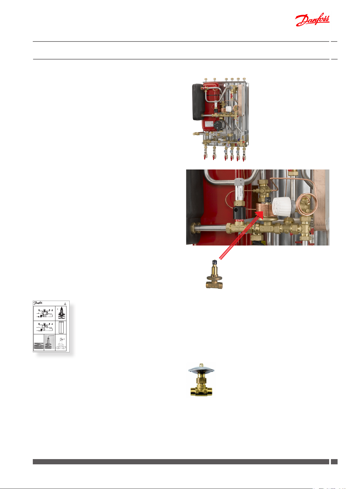
Akva Lux II VX
thermostatic control
Akva Lux II VX
thermostatic control,
and optional junction box
+ zone valve
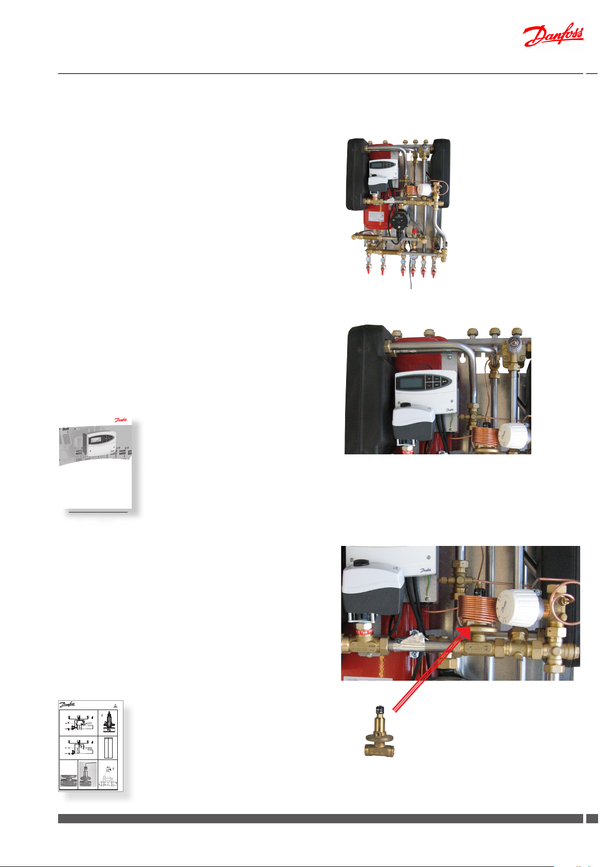
Akva Lux II VX
(ECL 110)
Akva Lux II VX
HWP (ECL210)
Akva Lux II VX
H2WP (ECL 210)
1. Contents
1.0 Contents .....................................................................................................................................................................................................................................1
2.0 Product introduction .............................................................................................................................................................................................................2
3.0 Dimensional sketches / connections ..............................................................................................................................................................................7
4.0 Enduser instructions, General ............................................................................................................................................................................................8
5.0 Enduser instructions, Initial adjustment and Setting ................................................................................................................................................9
6.0 Enduser instructions, Safety and Handling ................................................................................................................................................................ 11
7.0 Installation instructions - Getting started .................................................................................................................................................................. 12
8.0 Installation instructions, general .................................................................................................................................................................................... 13
9.0 Recirculation connection .................................................................................................................................................................................................. 19
9.1 Installation instructions - recirculation instructions ........................................................................................................................................ 20
10.0 Description of the Akva Lux II VX variants ................................................................................................................................................................... 21
10.1 Akva Lux II VX (thermostatic control) - 1 HE circuit + instantaneous DHW............................................................................................. 21
10.2 Akva Lux II VX (thermostatic control, optional junction box + zone valve) - 1 HE circuit + instantaneous DHW ..................... 24
10.3 Akva Lux II VX (ECL110) - 1 HE circuit + instantaneous DHW ....................................................................................................................... 27
10.4 Akva Lux II VX HWP (ECL 210/A237) - 1 HE circuit + instantaneous DHW ............................................................................................... 30
10.5 Akva Lux II VX H2WP (ECL 210/A260) - 2 HE circuits + instantaneous DHW ..........................................................................................32
11.0 Circulation pumps ................................................................................................................................................................................................................ 35
12.0 Domestic hot water (DHW) ............................................................................................................................................................................................... 39
12.1 Regulation of the domestic hot water temperature ....................................................................................................................................... 39
12.2 Bypass or circulation thermostat ........................................................................................................................................................................... 39
13.0 Maintenance ........................................................................................................................................................................................................................... 40
13.1 Maintenance schedule (recommendations) ...................................................................................................................................................... 41
14.0 Troubleshooting .................................................................................................................................................................................................................... 42
14.1 Troubleshooting - Heating ....................................................................................................................................................................................... 42
14.2 Troubleshooting - Domestic hot water ................................................................................................................................................................44
15.0 EU Declaration of Conformity .......................................................................................................................................................................................... 45
16.0 Commissioning Certicate ................................................................................................................................................................................................ 46
Danfoss District Energy VI.GP.Q3.02 DKDHR
11
Page 2
Instructions for installation and use Akva Lux II VX substations
2.0 Product introduction
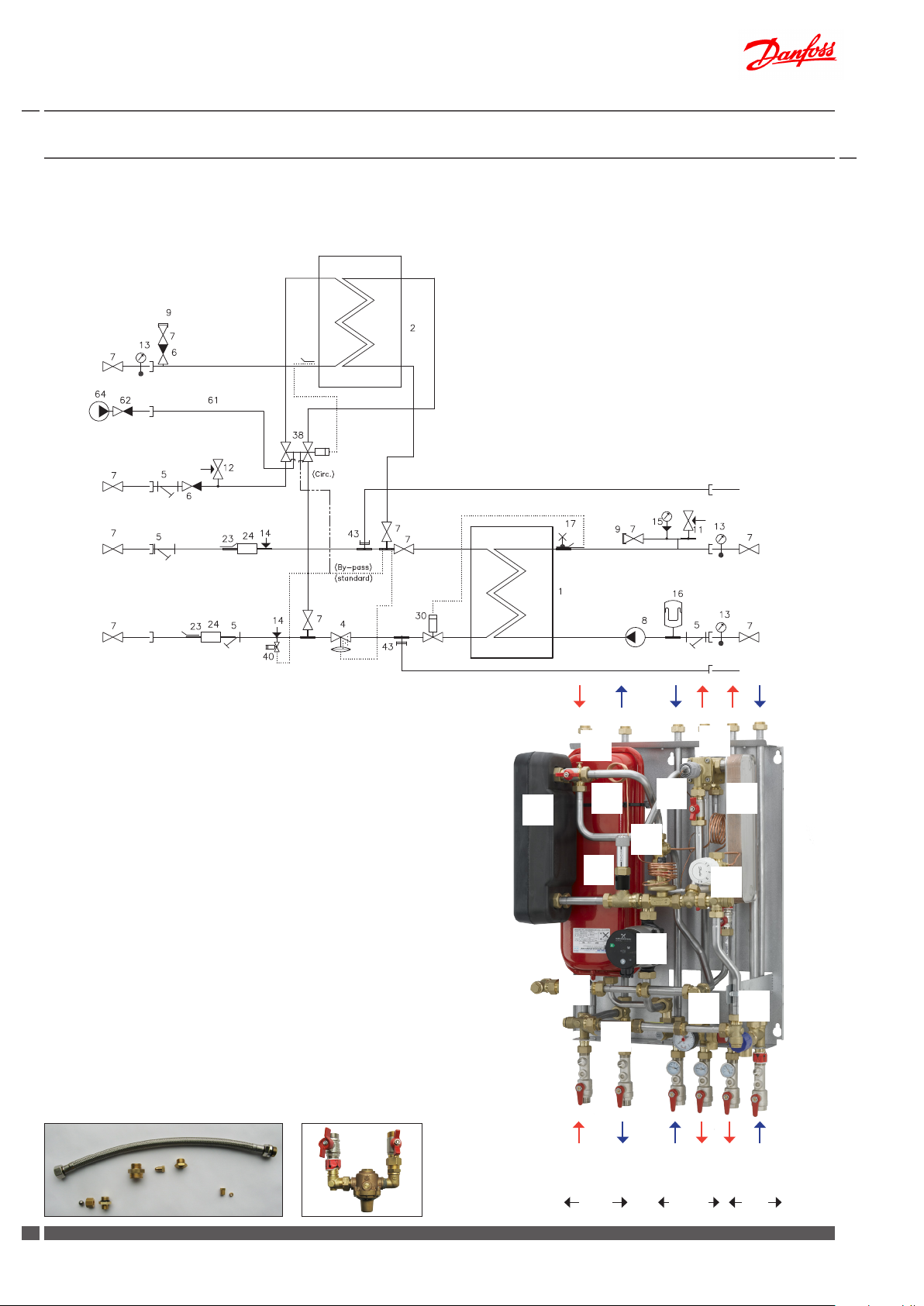
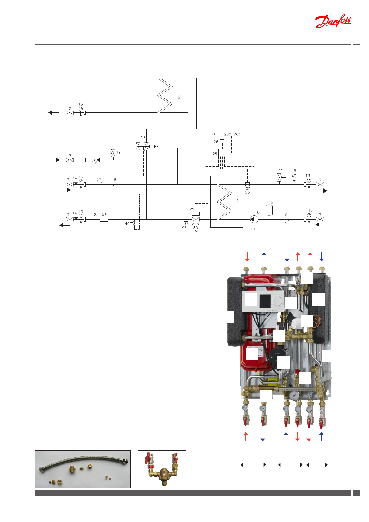
2.1 Akva Lux II VX (thermostatic control) - 1 HE circuit and instantaneous domestic hot water heater
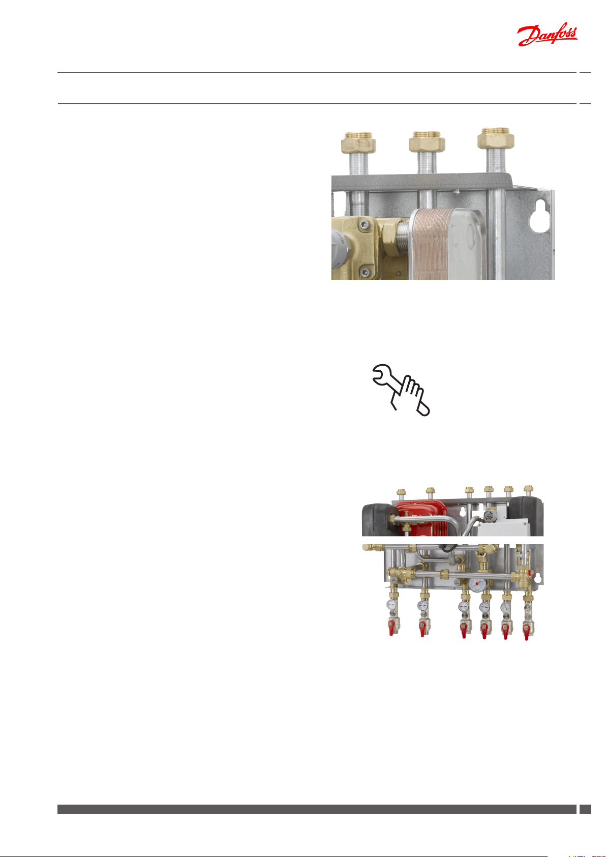
1 Plate heat exchanger, HE, insulated
2 Plate heat exchanger, DHW
4 Dierential pressure controller AVPL
5 Dirt strainer
6 Non-return valve
7 Ball valve
8 Circulation pump, HE
9 Plug
11 Safety valve, HE, 2.5 bar
12 Safety valve, DHW, 10 bar
13 Thermometer
14 Pocket for pressure gauge ¼
15 Manometer
DHW
Circ.
DCW
16 Expansion vessel 12 l
17 Air valve
23 Sensor pocket for heat meter ½“
24 Flex. tting piece for heat meter, 3/4” x 110-165 mm
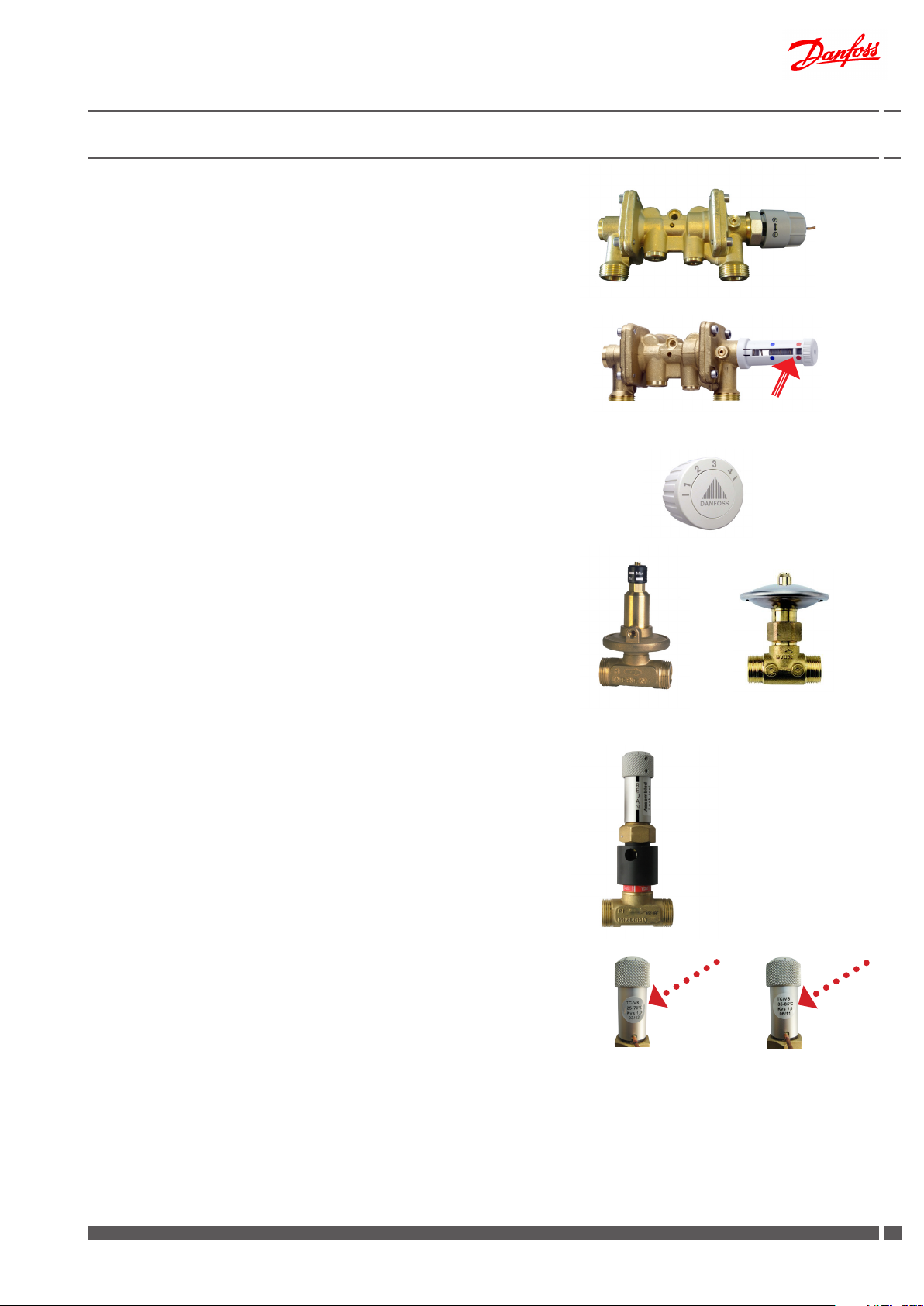
30 Thermostat T°C200 / VS2-15 or AVTB
38 PTC2 + P controller
40 Danfoss thermostat for bypass/circulation
--------------------------------------------------------------61 Recirculation hose (not part of the delivery)
62 Non-return valve (not part of the delivery)
64 Circulation pump DHW recirculation. (not part of the delivery)
DH
Supply
DH
Return
Principal components
1 Plate heat exchanger HE
2 Plate heat exchanger DHW
4 Dierential pressure controller
7 Ball valve (ll valve)
8 Circulation pump, HE
11 Safety valve, HE
12 Safety valve, DHW
16 Expansion vessel
17 Air valve
24 Fitting piece for heat meter
30 Thermostat T°C 200 / VS2
38 PTC2+P controller
40 Thermostat for bypass/circulation
The substation oers variable connection possibilities, as connection of pipes can be established both in the top or in the bottom of
the substation. Please note that the ball valves are supplied loose
with the substation, - for mounting on site.
Accessories available as extra equipment (mounting on site)
Recirculation pipe set - Div.736 - Code No. 004U8404
For systems that feature domestic hot water recirculation.
Rell line - Div.770 - Code No. 004U8668
To secure a constant pressure on the secondary side.
(Applicable on some markets, if in accordance with all local regulations, please check with your heating supplier).
Recirculation pipe set
Rell line
HE
Supply
HE
Return
38
17
17
16 2
1
16 2
38
7
4
30
30
40
8
24
24
11
12
24
DHW
DH return
DH supply
Primary
2
DKDHR VI.GP.Q3.02 Danfoss District Energy
HE return
HE supply
Secondary DHW
DCW
Page 3
Instructions for installation and use Akva Lux II VX substations
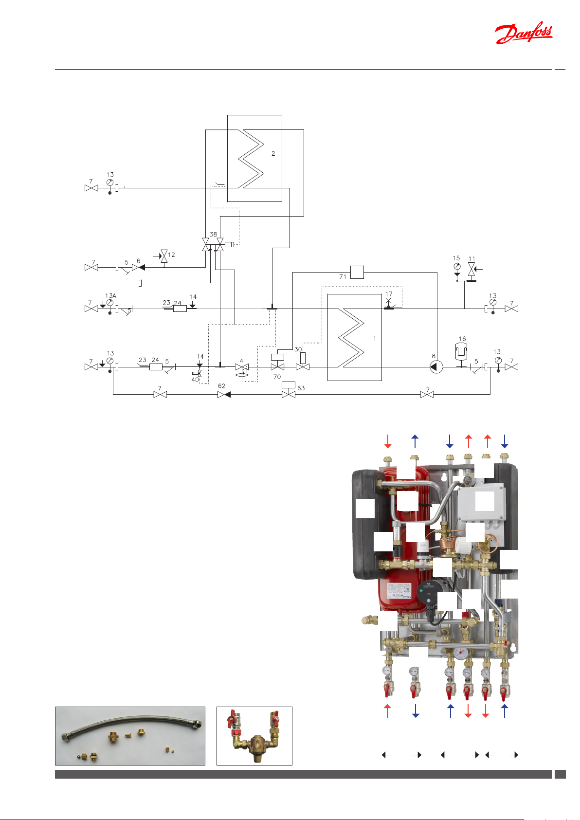
2.2 Akva Lux II VX (thermostatic control and optional junction box + zone valve) - 1 HE circuit and instantaneous DHW heater
1 Plate heat exchanger, HE, insulated
2 Plate heat exchanger, DHW, insulated
4 Dierential pressure controller AVPL
5 Dirt strainer
6 Non-return valve
7 Ball valve
8 Circulation pump, HE
11 Safety valve, HE
DHW
DCW
(Option: Circ. div. 736)
DH
Supply
DH
Return
Circ.
(option)
Bypass
(standard)
12 Safety valve, DHW
13 Thermometer 0 - 120° C
13A Thermometer 0 - 160° C
14 Pocket for pressure gauge ¼
15 Manometer
16 Expansion vessel
17 Air valve
23 Sensor pocket for heat meter ½“
24 Fitting piece for heat meter, 3/4” x 110 mm
30 Thermostat T°C200 / VS2-15
38 PTC2 + P controller
40 Danfoss thermostat for bypass/circulation
--------------------------------------------------------------Option: Rell line - delivered loose Options:
Ball valve 70 Zone valve
62 Non-return valve 71 Junction box
63 Pressure reducing valve Socla kv=3
(Option: Zone valve + junction box
HE
Supply
HE
Return
(Option: Rell line)
Principal components
1 Plate heat exchanger HE
2 Plate heat exchanger DHW
4 Dierential pressure controller
8 Circulation pump, HE
11 Safety valve HE
12 Safety valve DHW
16 Expansion vessel
17 Air valve
24 Fitting piece for heat meter
30 Thermostat T°C 200 / VS2
38 PTC2+P controller
40 Thermostat for bypass/circulation
70 Zone valve (Option)
71 Junction box (Option)
The substation oers variable connection possibilities, as connection of pipes can be established both in the top or in the
bottom of the substation. Please note that the ball valves are
supplied loose with the substation, - for mounting on site.
Accessories available as extra equipment (mounting on site)
Recirculation pipe set - Div.736 - Code No. 004U8404
For systems that feature domestic hot water recirculation.
Rell line - Div.770 - Code No. 004U8668
To secure a constant pressure on the secondary side.
(Applicable on some markets, if in accordance with all local regulations, please check with your heating supplier).
Recirculation pipe set
Rell line
17
16
1
16
70
38
71
40
30
2
4
12
11
8
24
24
24
DCW
DHW
DH supply
Primary
DH return
HE return
HE supply
Secondary DHW
Danfoss District Energy VI.GP.Q3 .02 DKDHR
33
Page 4
Instructions for installation and use Akva Lux II VX substations
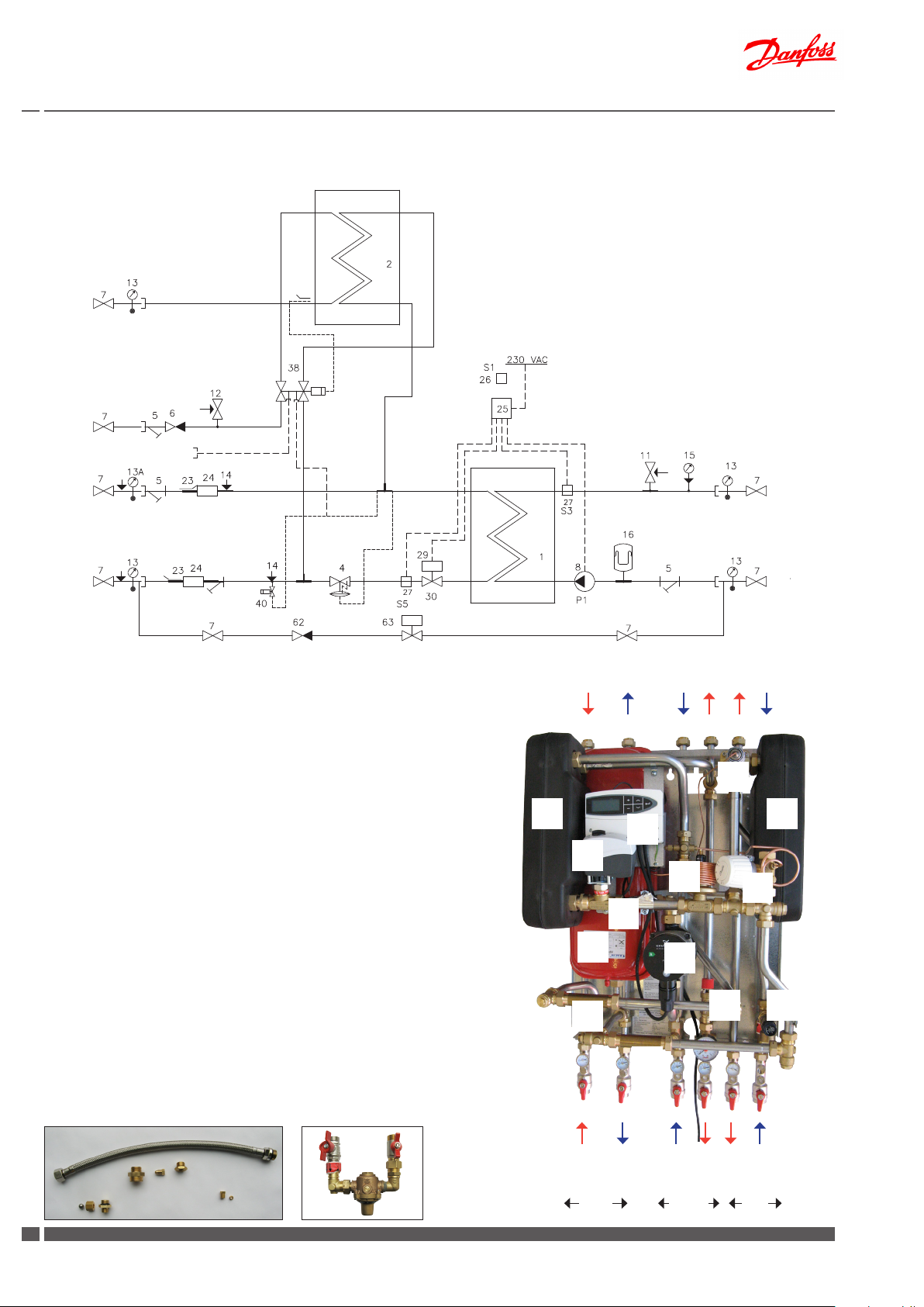
2.3 Akva Lux II VX (ECL 110) - 1 HE circuit and instantaneous domestic hot water heater
1 Plate heat exchanger, HE, insulated
2 Plate heat exchanger, DHW, insulated
4 Dierential pressure controller AVPL
5 Dirt strainer
6 Non-return valve
7 Ball valve
8 Circulation pump, HE
11 Safety valve, HE
DHW
DCW
(Option: Circ. div. 736)
DH
Supply
DH
Return
Circ.
(option)
Bypass
(standard)
12 Safety valve, DHW
13 Thermometer 0 - 120° C
13A Thermometer 0 - 160° C
14 Pocket for pressure gauge ¼
15 Manometer
16 Expansion vessel
23 Sensor pocket for heat meter ½“
24 Fitting piece for heat meter, 3/4” x 110 mm
25 Electronic controller Danfoss ECL 110
26 Outdoor sensor Danfoss ESMT
27 Sensor Danfoss ESMC
29 Danfoss actuator AMV 150
30 2-way valve VS2
38 PTC2 + P controller
40 Danfoss thermostat for bypass/circulation
--------------------------------------------------------------Option: Rell line - delivered loose
7 Ball valve
62 Non-return valve
63 Pressure reducing valve Socla kv=3
HE
Supply
HE
Return
(Option: Rell line)
Principal components
1 Plate heat exchanger HE
2 Plate heat exchanger DHW
4 Dierential pressure controller
8 Circulation pump, HE
11 Safety valve, HE
12 Safety valve, DHW
16 Expansion vessel
24 Fitting piece for heat meter
25 Electronic controller
29 Actuator AMV 150
30 2-way valve VS2
38 PTC2+P controller
40 Thermostat for bypass/circulation
The substation oers variable connection possibilities, as connection of pipes can be established both in the top or in the
bottom of the substation. Please note that the ball valves are
supplied loose with the substation, - for mounting on site.
Accessories available as extra equipment (mounting on site)
Recirculation pipe set - Div.736 - Code No. 004U8404
For systems that feature domestic hot water recirculation.
Rell line - Div.770 - Code No. 004U8668
To secure a constant pressure on the secondary side.
(Applicable on some markets, if in accordance with all local regulations, please check with your heating supplier).
Rell lineRecirculation pipe set
38
1
2
25
29
4
40
30
16
24
8
11
12
24
DHW
DH return
DH supply
Primary
4
DKDHR VI.GP.Q3.02 Danfoss District Energy
HE return
HE supply
Secondary DHW
DCW
Page 5
Instructions for installation and use Akva Lux II VX substations
2.3 Akva Lux II VX HWP (ECL 210/A237) - 1 HE circuit and instantaneous domestic hot water heater
1 Plate heat exchanger, HE, insulated
2 Plate heat exchanger, DHW, insulated
5 Dirt strainer
6 Non-return valve
7 Ball valve
8 Circulation pump, HE
11 Safety valve, HE
DHW
12 Safety valve, DHW
13 Thermometer
14 Pocket for pressure gauge ¼
15 Manometer
16 Expansion vessel
23 Sensor pocket for heat meter ½“
24 Fitting piece for heat meter, 3/4” x 110 mm
25 Electronic controller Danfoss ECL 210/A237
26 Outdoor sensor Danfoss ESMT
27 Sensor Danfoss ESMC
29 Danfoss actuator AMV 150
30 Multifunctional control valve AHQM
38 PTC2 + P controller
40 Danfoss thermostat for bypass/circulation
--------------------------------------------------------------Options.:
Recirculation set
Electronic Danfoss Controller ECL 310
DCW
Circ.
(option)
DH
Supply
Bypass
DH
Return
Principal components
1 Plate heat exchanger HE
2 Plate heat exchanger DHW
5 Strainer
8 Circulation pump, HE
11 Safety valve, HE
12 Safety valve, DHW
16 Expansion vessel
24 Fitting piece for heat meter
25 Electronic controller ECL 210/A237
29 Actuator AMV 150
30 Multifunctional control valve AHQM
38 PTC2+P controller
40 Thermostat for bypass/circulation
The substation oers variable connection possibilities, as connection of pipes can be established both in the top or in the
bottom of the substation. Please note that the ball valves are
supplied loose with the substation, - for mounting on site.
HE
Supply
HE
Return
38
25
29
1
2
40
30
16
12
8
11
Accessories available as extra equipment (mounting on site)
Recirculation pipe set - Div.736 - Code No. 004U8404
For systems that feature domestic hot water recirculation.
Rell line - Div.770 - Code No. 004U8668
To secure a constant pressure on the secondary side.
(Applicable on some markets, if in accordance with all local regulations, please check with your heating supplier).
Rell lineRecirculation pipe set
Danfoss District Energy VI.GP.Q3 .02 DKDHR
5
DH supply
Primary
24
DH return
5
HE return
HE supply
Secondary DHW
DHW
DCW
55
Page 6
Instructions for installation and use Akva Lux II VX substations
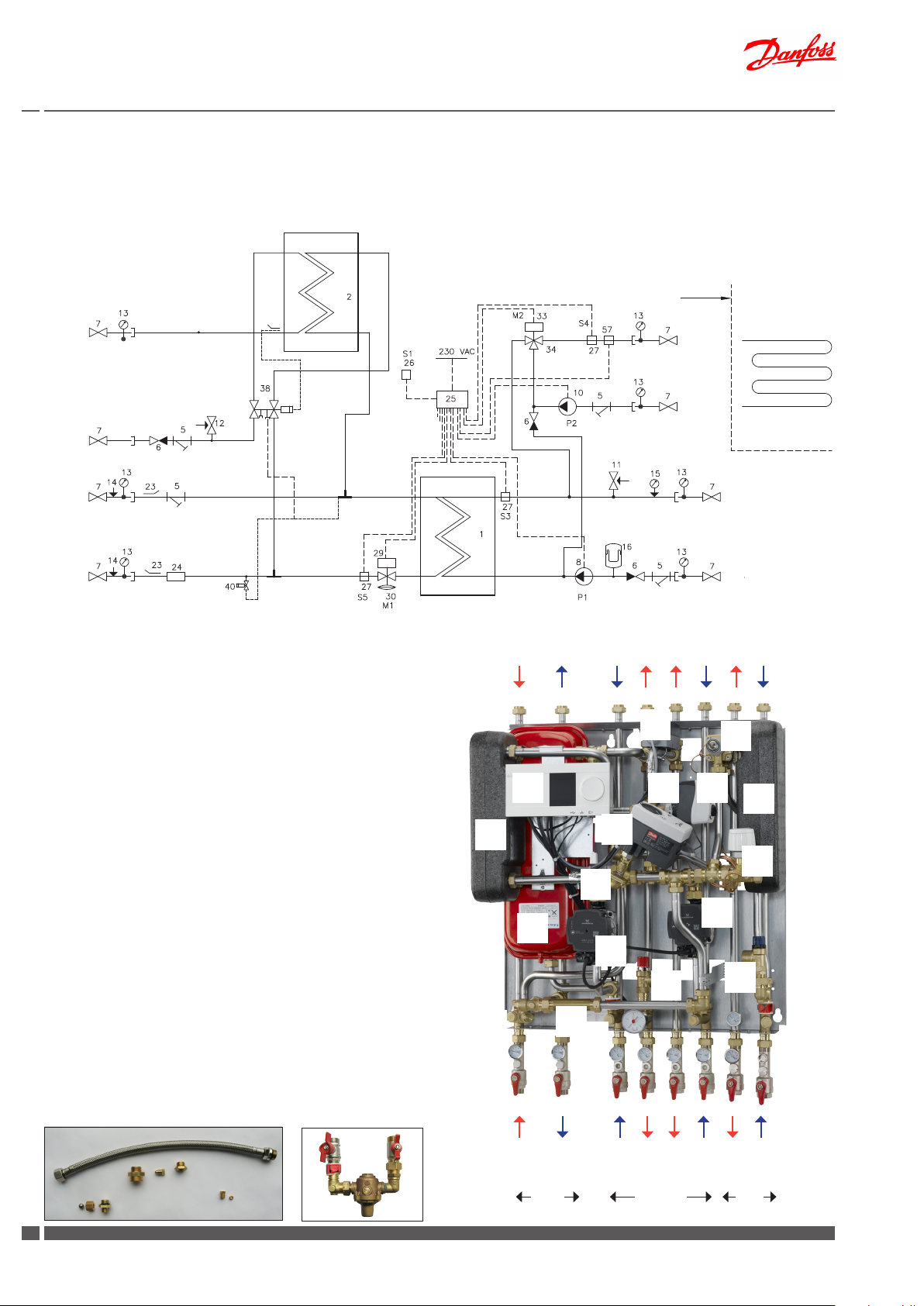
2.4 Akva Lux II VX H2WP (ECL 210/A260) - 2 HE circuits and instantaneous domestic hot water heater
1 Plate heat exchanger, HE, insulated
2 Plate heat exchanger, DHW, insulated
5 Dirt strainer
6 Non-return valve
7 Ball valve
8 Circulation pump, HE
10 Circulation pump, FH
11 Safety valve, HE
12 Safety valve, DHW
13 Thermometer
14 Pocket for pressure gauge ¼
15 Manometer
16 Expansion vessel
23 Sensor pocket for heat meter ½“
24 Fitting piece for heat meter, 3/4” x 110 mm
25 Electronic controller Danfoss ECL 210/A260
26 Outdoor sensor Danfoss ESMT
27 Sensor Danfoss ESMC
28 Immersion sensor ESMB
DHW
DCW
Circ.
(option)
DH
Supply
Bypass
DH
Return
Principal components
1 Plate heat exchanger HE
2 Plate heat exchanger DHW
5 Dirt strainer
8 Circulation pump, HE
10 Circulation pump, FH
11 Safety valve, HE
12 Safety valve, DHW
16 Expansion vessel
24 Fitting piece for heat meter
25 Electronic controller
29 Actuator AMV 13
30 Multifunctional control valve AHQM
33 Actuator AMV 150
34 3-way valve VMV
38 PTC2+P controller
40 Thermostat for bypass/circulation
57 Safety thermostat
The substation oers variable connection possibilities, as connection of pipes can be established both in the top or in the
bottom of the substation. Please note that the ball valves are
supplied loose with the substation, - for mounting on site.
Accessories available as extra equipment (mounting on site)
Recirculation pipe set - Div.736 - Code No. 004U8404
For systems that feature domestic hot water recirculation.
Rell line - Div.770 - Code No. 004U8668
To secure a constant pressure on the secondary side.
(Applicable on some markets, if in accordance with all local regulations, please check with your heating supplier).
Rell lineRecirculation pipe set
29 Danfoss actuator AMV
30 Multifunctional control valve AHQM
33 Danfoss actuator AMV
34 Three-way valve VMV
38 PTC2 + P controller
40 Danfoss thermostat for bypass/circulation
29 Danfoss actuator AMV, HE
57 Safety thermostat
Supply limit
HE
Supply
HE
Return
57
25
1
34 33
29
38
2
40
30
10
16
8
11
5
24
5
12
DHW
DH return
DH supply
Primary
6
DKDHR VI.GP.Q3.02 Danfoss District Energy
HE return
HE supply
Secondary DHW
FH supply
FH return
DCW
Page 7
Instructions for installation and use Akva Lux II VX substations
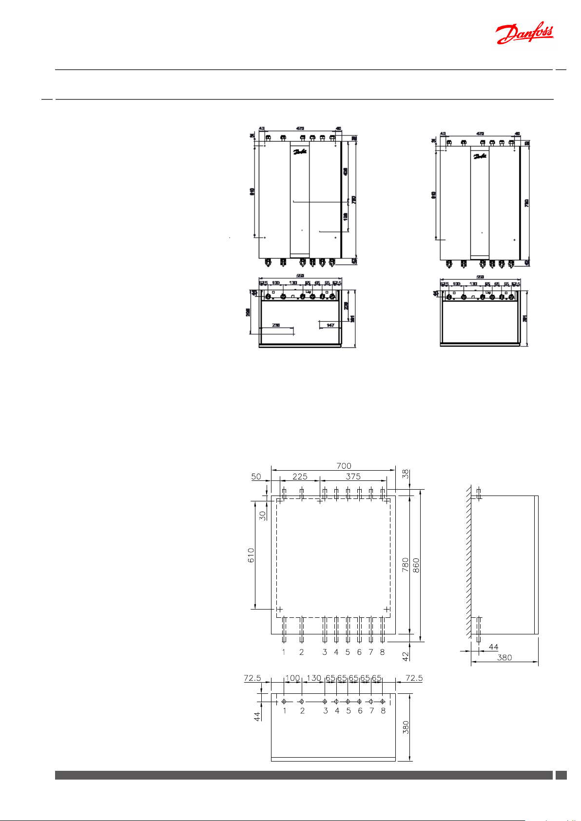
3.0 Dimensional sketches / connections
Dimensions mm:
Without cover:
H 860 x W min. 510 / max. 553* x D 365
With cover:
H 861 x W 550 x D 365
H 861 x W 600 ** x D 381
* Units with insulated plate heat exchanger type XB06H-1 40
for both HE and DHW circuits.
** Width of cover for units with insulated plate heat exchanger
type XB06H-1 40 for both HE and DHW circuits
.
Connections sizes:
Akva Lux II VX (thermostatic control)
DH + DCW + DHW + HE: G ¾” (int. thread)
Connections, Circ.: R ½” (int. thread)
*
Substations with XB 0 6L-24 heat exchanger for o or heating are
supplied with connection pipes for radiators for direct connection.
Akva Lux II VX (thermostatic control and optional
junction box + zone valve) +
Akva Lux II VX (electronic control)
DH: G¾” (ET)
DCW, DHW, HE: G¾” (IT)
Circ. R½” (ET)
Akva Lux II VX - 1 HE circuit + domestic hot water
Wall
A DB FEC
H
G
top view
Connections:
Order:
A. District heating (DH) supply
B. District heating (DH) return
C. Heating (HE) return
D. Heating (HE) supply
E. Domestic hot water (DHW
F. Domestic cold water (DCW)
G. Connection return
H. Connection supply *
*
Wall
A DB FEC
top view
Connections:
Order:
A District heating (DH) supply
B District heating (DH) return
C Heating (HE) return
D Heating (HE) supply
E DHW
F DCW
Dimensions mm:
Without cover:
H 861 x W 650 x D 365
With cover:
H 861 x W 700 x D 380
Connections:
Order:
1 District heating (DH) supply
2 District heating (DH) return
3 Heating (HE) return
4 Heating (HE) supply
5 Floor heating (FH) supply
6 Floor heating (FH) return
7 DHW
8 DCW
Connections size:
DH: G¾” (ET)
DCW, DHW, HE, FH: G¾” (IT)
Circ. R½” (ET)
Akva Lux II VX - 2 HE circuits + domestic hot water
Zirk.
Wall
top view
Danfoss District Energy VI.GP.Q3 .02 DKDHR
77
Page 8
Instructions for installation and use Akva Lux II VX substations
4.0 Enduser instructions, General
Instructions
Please read these instructions carefully before installing and commissioning this substation. The manufacturer accepts no liability for loss
or damage resulting from failure to comply with these instructions
for use. Read and follow these instructions carefully to prevent the
risk of physical injury and/or damage to property. Exceeding the
recommended operating parameters appreciably increases the risk
of personal injury and/or damage to property.
Installation, commissioning and maintenance must be carried out
by qualied and authorised personnel (both plumbing and electrical work).
Once the station has been installed and is operating, there is nor-
mally no need to alter the settings or other functions. The district
heating substation is very reliable and easy to operate.
If necessary, you can change the temperature settings as described
on page 10. For more detailed information about the substation,
see the sections concerning installation and commissioning.
Description
These instructions apply to substation types Akva Lux II VX, which
are district heating substations for indirect heating for single-family
houses, semi-detatched and terraced houses as well as ats. With
one or two heating circuits for radiator and/or oor heating and with
instantaneous water heater for domestic hot water heating. For wallmounting and with variable connection possibilities.
The HE supply temperature is controlled either by a self-acting thermostat T°C 200 or AVTB or by a Danfoss ECL controller in combination
with an electronic actuator. The ECL controller acts as the brain of
the heating system. It lets you easily control and optimize system
performance and operation.
Warning! Hot surfaces
Parts of the substation may be very hot and can cause burn injuries. Be very careful when you are in the immediate vicinity of
the unit.
Warnings about high pressure and high temperature
The maximum supply temperature in the district heating network can be up to 120°C (130° C*) and the operating pressure can
be up to 16 bar. This may result in a risk of scalding from touching
the substation and from outow of the medium (water/steam).
Exceeding the substation design data and operating parameters
for pressure and temperature carries an appreciable risk of personal injury and/or damage to property.
Emergencies
In the event of re, leaks or other hazards, immediately shut o
all sources of energy to the substation, if possible, and call for
appropriate assistance.
If the domestic hot water is discoloured or malodorous, shut o
all ball valves on the substation notify all users and call for professional assistance without delay.
*
the substations can work temporarily at 130° C
We recommend regular inspections of the substation - ideally in
connection with readings of the district heating meter.
Pay special attention to any leaks and an excessively high return
temperature in the district heating circuit (poor cooling of the district
heating water). Cooling – i.e. the dierence between the supply and
return temperature of the district heating water – has a signicant effect on the overall energy economy. Therefore, it is important to focus
on the supply and return temperature in the heating system.
The dierence should typically be 30–35°C in systems that operate
with radiators. In systems that feature oor heating, the dierence
is typically 5–10°C. In oor heating systems, the supply temperature
should not exceed 35°C.
Cooling from the water heater alone:
During tapping, the level of cooling will typically be 30–35°C. When
domestic hot water is not being tapped, it is completely normal for the
return temperature from the water heater to rise slightly. In this situation, the district heating meter will register very modest consumption
as the volume of water is very small.
On substations with recirculation, the calorie meter registers the heat
loss in the recirculation pipe.
Irregularities
When reading the meters, check all joints and connections for leaks.
If you identify any irregularities/leaks, contact your professional
provider for assistance.
Check the troubleshooting section before contacting your
professional provider.
8
DKDHR VI.GP.Q3.02 Danfoss District Energy
Page 9
Instructions for installation and use Akva Lux II VX substations
5.0 Enduser instructions, Initial adjustment and Setting
Domestic hot water control
Danfoss PTC2+P controller (Fig. 1) for domestic hot water. Set the DHW
temperature by moving the adjuster lever towards “+” (hotter) or “-”
(colder).
Start by turning the lever clockwise – until it stops/until you cannot turn it
any further. Then turn the lever counter-clockwise until the temperature
of the tap water is approx. 48°C during normal tapping ow (7–8 litres
per min.). The temperature must never exceed 55°C to prevent limescale
deposits building up in the water heater.
Fig. 1
Option: Alternatively the VX substations may be tted with a Danfoss
PM2+P controller (Fig. 2) for domestic hot water. Set the DHW temperature
by turning the adjuster lever towards red (hotter) or blue (colder). Start
by turning the lever clockwise – until the pin is opposite the blue dot.
Then turn the lever counter-clockwise until the temperature of the tap
water is approx. 48°C during normal tapping ow (7–8 litres per min.).
The temperature must never exceed 55°C to prevent limescale deposits
building up in the water heater.
Bypass or circulation thermostat
Thermostat (Fig. 3) that keeps the branch pipe warm in the summer
or regulates the circulation temperature if domestic hot water recirculation has been established in the hot water system (see pages 20-21
and page 37 for more information).
The thermostat should initially be set to position 3.
Heating circuit, Dierential Pressure Controller
The dierential pressure controller (Fig. 1) reduces the high, uctuating
pressure in the district heating network to a constant operating pressure.
The AVPL dierential pressure controller is initially set by the plumber in
connection with the commissioning of the substation. If disruptions to
the operation occur: noise in the radiator thermostats or poor regulation
capacity, it may be necessary to reset the dierential pressure controller
to a lower or higher operating pressure. We suggest that you contact
your local plumber for assistance.
The TD200 dierential pressure controller is preset from factory and
should not be adjusted afterwards.
Heating circuit, Temperature control
Thermostatic control
The supply temperature to the substation can be set by adjusting the thermostat TC (Fig. 5), which controls the temperature for the heating circuit.
The thermostat will be set by the installer in connection with the com
missioning, but it may be necessary to adjust it subsequently depending
on the outdoor temperature.
Approximate thermostat scale settings:
Pos. 2 = 30°C
3 = 40°C for range 25-70° C
4 = 50°C
5 = 60°C
or
Pos. 2 = 45°C
3 = 55°C for range 35-85° C
4 = 65°C
5 = 75°C
Please note that a label on the TC thermostat will indicate the temperature
range (g. 6).
The setting values may vary depending on the operating conditions. It is
important to set the supply temperature to the radiators as low as possible. Use the radiator thermostats to regulate the room temperature.
NB! For houses that are heated exclusively with oor heating.
The supply temperature should typically be set to approx. 30–35°C.
ALWAYS refer to the instructions from the oor supplier.
Fig. 2
pin
Fig. 3
Fig. 4
or
TD200AVPL
Fig. 5A
-
Fig. 6
or
Range 35-85° CRange 25-70° C
Danfoss District Energy VI.GP.Q3 .02 DKDHR
99
Page 10
Instructions for installation and use Akva Lux II VX substations
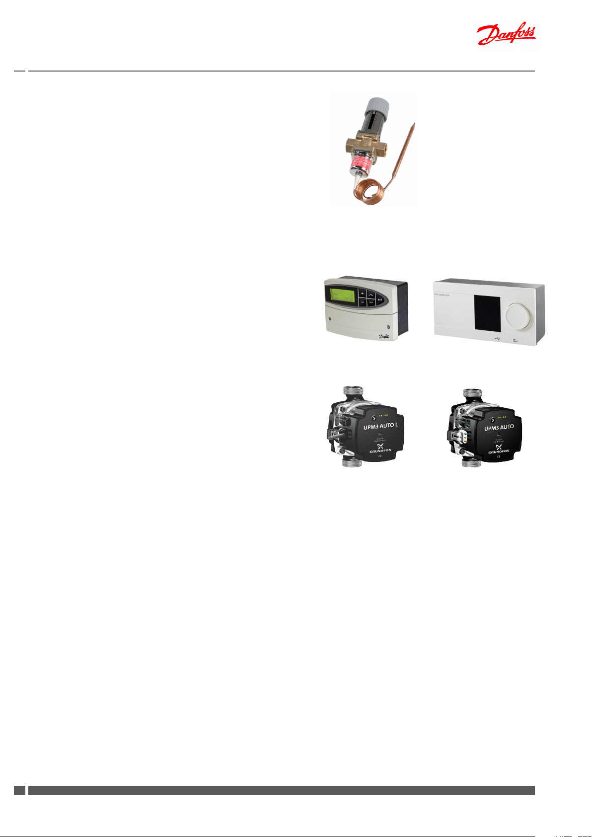
Alternatively the HE temperature is controlled by a self-acting temperature controller Danfoss AVTB (Fig. 5B). The controller has a control
valve, thermostatic actuator and handle for temperature setting. The
thermostat will be set by the installer in connection with the commissioning, but it may be necessary to adjust it subsequently depending
on the outdoor temperature.
Approximate thermostat scale settings:
1.0 = 35 °C
1.5 = 45 °C
2.0 = 55 °C
2.5 = 65 °C
3.0 = 75 °C
Other variations with other types of thermostatic valves for control
of the heating circuit may occur.
Electronic control
The temperature for the heating circuit can be controlled electronically by a Danfoss ECL 110, a Danfoss ECL 210 or a Danfoss ECL 310
controller (Fig. 6). The supply temperature ist calculated by the controller on basis of the outdoor temperature.
See the enclosed documentation for same.
Pump.
Akva Lux II VX substations are factory tted with a pump (Fig. 7). The
pump setting is established in connection with the commissioning. Generally speaking, this setting is not to be altered. If it should nevertheless
be necessary to change the pump setting, see the section concerning
pumps in the installation and commissioning sections regarding the
individual products.
In the summer, you can switch o the power to the pump at the mains
if you want to save electricity by not heating your home.
Start-up and venting – see the installation and commissioning sections,
if necessary.
Fig. 5B
AVTB
Fig. 6
or
ECL 210 / ECL 310ECL 110
Fig. 7
UPM3 AUTOUPM3 AUTO L
10
DKDHR VI.GP.Q3.02 Danfoss District Energy
Page 11
Instructions for installation and use Akva Lux II VX substations
6.0 Installation instructions, Safety and Handling
Instructions
Please read these instructions carefully before installing and comissioning this substation. The manufacturer accepts no liability for loss or
damage resulting from failure to comply with these instructions for use.
Read and follow these instructions carefully to prevent the risk of physical injury and/or damage to peroperty. Exceeding the recommended
operating parameters considerably increases the risk of personal injury
and/or damage to property.
Installation, commissioning and maintenance must be carried out by
qualied and authorized personnel in compliance with the local safety
regulations.
Once the station has been installed and is operating, there is normally
no need to alter the settings or other functions. The district heating
substation is very reliable and easy to operate.
Energy source
The substation is primarily designed for connection to district heating.
Alternative energy sources can be used if the operating conditions are
equivalent to district heating at all times.
Application
The substation is designed only to operate with water or a water-glycol
mixture (up to 40%), and other heating media may not be used.
The substation is to be connected to the household piping in a frost-free
room, where the temperature does not exceed 50 °C and the relative
humidity is not higher than 80%. The substation must no be covered,
bricked in or otherwise cut o from access.
Choice of materials
Only use materials, that comply with local regulations.
Corrosion
The maximum chloride compounds of the medium must not be higher
than 300 mg/l. The risk of corrosion increases considerably if the recommended chloride content is exceeded.
Safety valve(s)
Installation of safety valve(s) must always be in compliance with local
regulations.
Noise level.
≤ 55 dB.
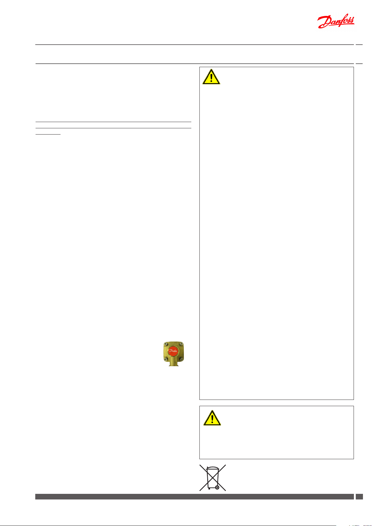
PTC2+P controller for domestic hot water
The controller is preset from factory and sealed with a
red sticker. This sealing must not been broken.
The warranty becomes void if the sealing is broken.
Storage
Before installation, the units must be stored in a dry, heated (i.e. frostfree) room.
(Relative humidity max. 80% and storage temperature 5-70 °C).
The units must not be stacked higher than the limit at the factory (max.
8 layers) Units supplied in cardboard packaging must be lifted using the
handles incorporated in the packaging. Units must be placed on pallets
for transport/moving across large distances.
As far as possible, do not lift the substation by the pipes. Lifting by the
pipes may cause leaks. REMEMBER to retighten.
Disposal
Dispose of the packaging in accordance with the local regulations for
disposal of used packaging materials.
The substation is made of materials that cannot be disposed of together
with household waste.
Close all energy sources and disconnect all connection pipes. Disconnect
and dismantle the product for disposal in accordance with the applicable
local regulations for the disposal of the individual components.
Danfoss District Energy VI.GP.Q3 .02 DKDHR
Connection
It must be possible to cut o all energy sources to the unit - including electrical connections - at all times.
Potential equalization/grounding
Potential equalization is an electrical equalizer connection to secure
against user contact with dangerous voltage, which may occur for
example between two piping systems. Potential equalization reduces
corrosion in heat exchangers, water heaters, district heating units and
plumbing installations. Equalization of potentials should be eected
according to local regulations.
Warning! Hot surfaces
Parts of the substation may be very hot and can cause burn injuries. Be very careful when you are in the immediate vicinity of the
substation.
Warning of high pressure and high temperature
The maximum supply temperature in the district heating network
can be up to 120°C (130°C*) and the operating pressure can be up
to 16 bar. This may result in a risk of scalding from touching the substation and from outow of the medium (water/steam). Exceeding
the substation design data and operating parameters for pressure
and temperature carries an appreciable risk of personal injury and/
or damage to property.
* the substation can work temporarily at130°C.
Emergencies
In the event of re, leaks or other hazards, immediately shut o all
sources of energy to the substation, if possible and call for appropriate assistance.
If the domestic hot water is discoloured or malodorous, shut o all
ball valves on the substation, notify all users and call for professional
assistance immediately.
Warning of damage during transport
On reception of the substation, and before installing it, check for
any evidence of damage during transport.
The substation must be handled and moved with the greatest care
and attention.
NB! - Tightening of connections
Before mounting of the substation, ALL pipe connections MUST
be retightened, as vibrations during transport may have caused
leaks. Once the substation has been put into operation ALL pipe
connections MUST be pressure tested for leaks and retightened
once more if necessary.
DO NOT OVERTIGHTEN THE PIPE CONNECTIONS – see page 14,
“Test & connections”.
Handling
We recommend that you wear suitable safety footwear while
handling and installing the substation.
1111
Page 12
Instructions for installation and use Akva Lux II VX substations
7.0 Installation instructions - Getting started
Connect the substation to the household piping in accordance with
the labelling at the bottom and/or in accordance with the instructions in this manual.
If the system features DHW recirculation, a recirculation connection must be established on the substation. The circulation set
is optional equipment, which must be ordered separately and
mounted on site.
We recommend establishing recirculation BEFORE mounting the
substation on the wall.
For instructions about recirculation connection, see page 20-21.
Commissioning
Please note that from factory the substation is prepared for
connection in bottom of the substation.
1. The ball valves, which are supplied loose with the substation, can
be mounted either on the top connections or bottom connections. For connection in top, demount the plugs from the top connections and mount them on the bottom connections.
(Please see instruction on page 14 for further information)
2. For connection in TOP for DCW and DHW please note that
this includes relocation of the built-in blind plates BEFORE
mounting the substation on the wall. (Please see instruction
on page 15 for further information).
3. If the household piping system features domestic hot water
recirculation, the substation must be connected to the recirculation system. See pages 20-21 for further information about
DHW recirculation.
4. The substation is prepared for wall mounting. Mount the substation on a solid wall using two sturdy bolts, screws, expansion bolts or similar.
5. Close all shut-o valves in the substation before connecting it/
them to the household piping.
6. Mount the district heating meter (see page 16).
7. IMPORTANT! Tighten all pipe connections, as they may have
loosened during transport and handling.
8. On systems that feature a safety valve, establish a drain connection in compliance with the applicable legislation.
9. Fill the heat exchanger / the system with water according
to the instructions on pages 18 and 19 until the manometer
shows a working pressure, which corresponds to the system
height + approx. 5 m (approx. 1.2 - 1.5 bar).
12. Pressure test the entire system for leaks in accordance with
the applicable regulations.
13. Connect pump and automatic components, if any, to the electricity supply, but do not switch on the power.
14. Heat the system and vent the radiator circuit/heating side
thoroughly on the radiators and the air valve, if any.
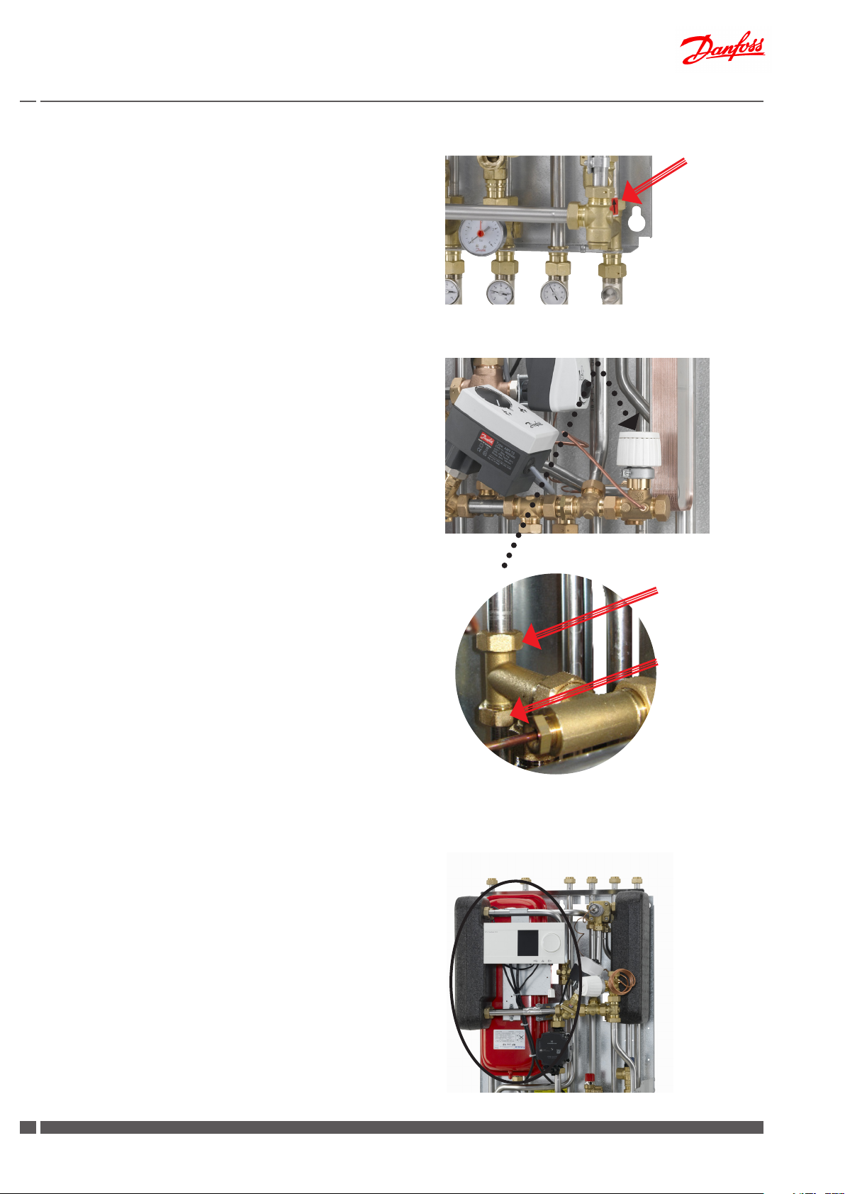
15. For substations, which include zone valve, remember
to remove the red split on the position indicator of
the zone valve.
16. Now switch on the pump and automatic components, if any.
10. Finally open the ball valve for the DH supply and return ow
and heat up the system.
11. Check the substation and the household piping thoroughly
for leaks.
12
DKDHR VI.GP.Q3.02 Danfoss District Energy
17. Finish by adjusting the substation in accordance with the
instruction manuals.
Heating and cooling the substation may cause leaks. Therefore
it may be necessary to retighten the connections in the period
after commissioning.
Page 13
Instructions for installation and use Akva Lux II VX substations
8.0 Installation instructions, general
The installation, connection and maintenance of the substation must
be performed by qualied and authorised personnel.
Installation must always be performed in accordance with the applicable legislation and in compliance with these instructions.
The substation must be installed so that it is freely accessible and can
be maintained without unnecessary disruption. Lift the substation
by its mounting plate and secure it to a solid wall using 2 sturdy
bolts, screws or expansion bolts positioned in the two keyholes in
the mounting plate.
Before commissioning, rinse all the pipes in the household piping
system thoroughly to remove any impurities, and check and clean
the dirt strainers in the substation.
Connect the substation to the household piping in accordance with
the labelling at the bottom and/or in accordance with the instructions in this manual.
Test and connections
Before lling the system with water, retighten all the pipe connections
because vibrations and shocks during transport and handling may
have caused leaks. Once the system has been lled with water, tighten
all the pipe connections once more before performing pressure test
for leaks. After heating of the system, check all the connections and
retighten if necessary.
Please note that the connections feature EPDM rubber gaskets!
Therefore, it is important that you DO NOT OVERTIGHTEN the union
nuts. Over-tightening may result in leaks. Leaks caused by overtightening or failure to retighten connections are not covered by
the warranty.
Variable connections possibilities
The Akva Lux II VX substations oer variable connection possibilities, as connections of pipes can be established in the top or in the
bottom of the substation. - Upon delivery the substation is prepared
for connction in bottom of the substation. Please note that the ball
valves are supplied loose and must be mounted on site.
For change of connection from bottom to top, demount plugs on
connection pipes in top of substation and ball valves on connection
pipes in bottom of substation, and mount plugs in connection pipes
in bottom of substation and ball valves on connection pipes in top
of substation.
These variable connection possibilities makes it possible to establish
some of the connections in the top and others in the bottom of the
substation. This may be desirable in some cases.
Danfoss District Energy VI.GP.Q3 .02 DKDHR
1313
Page 14
Instructions for installation and use Akva Lux II VX substations
PLEASE NOTE!
Remember to use gaskets when establishing connection in top of
unit.
DCW
If there is a need for a domestic cold water outlet in top of the unit,
remove the blind plate in pos. A and demount the plug in top of the
unit.
For DCW inlet in top of the unit, remove the plug in top of the unit
and the blind place in pos. A. Mount the ball valve in top and use
the plug for plugging in the bottom (remember gaskets).
DHW
For DHW outlet in top of the unit, remove the blind plate and gasket
from Pos. B and relocate to Pos. C - see photos to the right.
The blind plate should be installed in Pos. C to prevent a pocket
of standing water that at worst can produce dangerous bacteria.
Therefore, it is extremely important to install the blind plate as
shown.
Also move the plug from the top connection to the DHW outlet in
the bottom of the unit and mount the ball valve in top (remember
gaskets).
DHW both up and down
The unit can be connected with piping both up and down for the domestic hot water. Remove blind plate in pos. B and plug in top of unit.
DCW
DHW
A
Demount
blind plate
Heating (HE)
The unit can be connected with piping both up and down on the
heating side. Remove the plugs in top of unit, and establish connection upwards.
Expansion vessel
The Akva Lux II VX substations are equipped with an expansion
vessel, which is factory set to 0,5 bar.
DHW
Demount
blind plate
B
Mount blind
C
plate here
14
DKDHR VI.GP.Q3.02 Danfoss District Energy
Page 15
Instructions for installation and use Akva Lux II VX substations
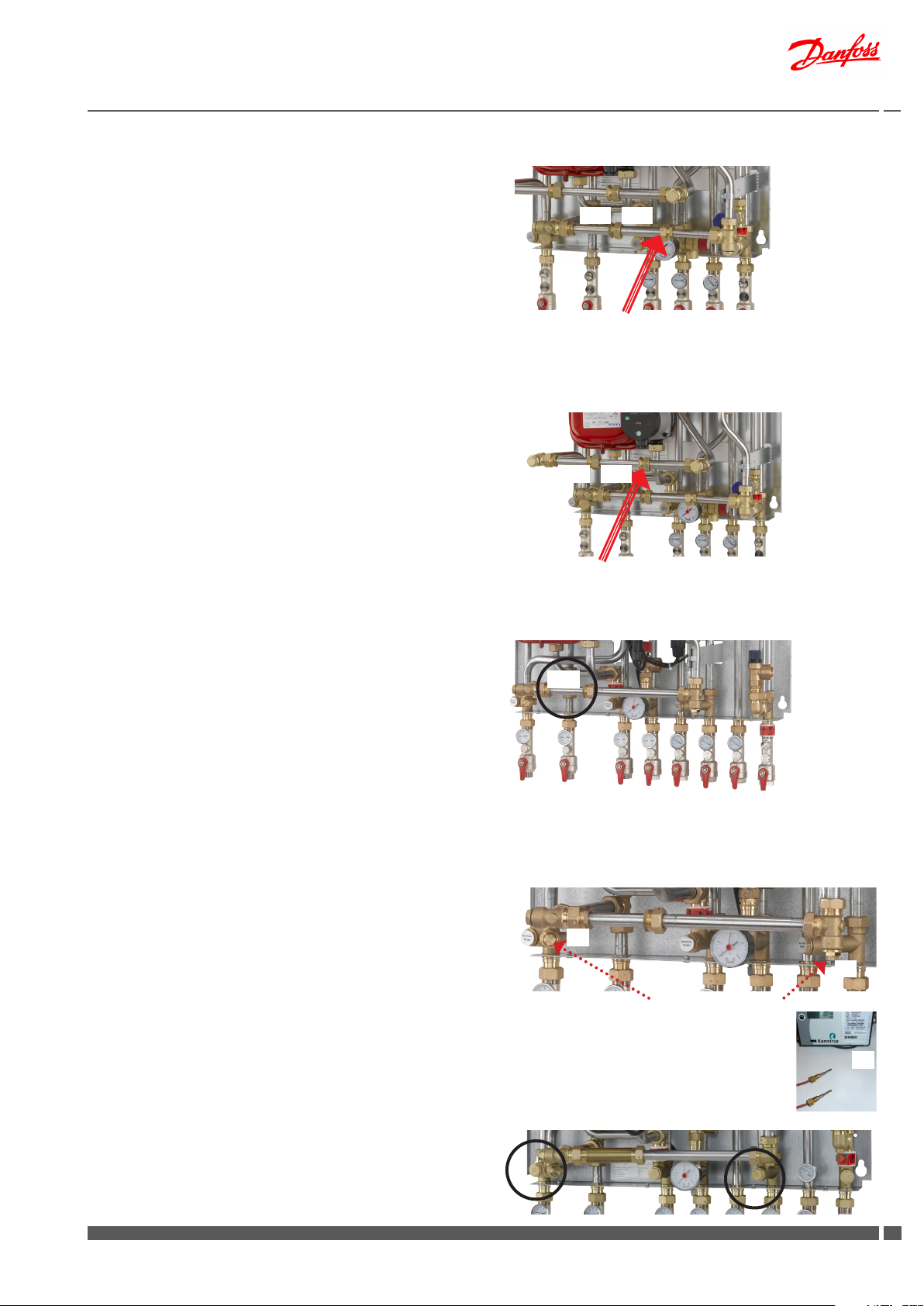
Fitting piece(s) for heat meter(s).
The Akva Lux II VX substations are equipped with tting piece(s) for
heat meter in both DH supply and return (leak detection) or only in
DH return.
The tting piece(s) can be either exible size 3/4 x 110 - 165 mm or
xed size 3/4” x 110 mm.
Variations with other dimensions may occur.
Fitting of heat meter in substation with exible tting piece
size 3/4 x 110 - 165 mm
Fitting of heat meter in DH return - (Fig. 1)
The heat meter can easily be tted on site as follows:
- Close the ball valves on the district heating and the heating
lines.
- Loosen the union nuts at both ends of the nipple pipe 24
remove nipple pipe 24
1
and insert heat meter and tighten
1
.
- do not forget gaskets.
- For heat meters with an overall length of more than110 mm
the exible tting pipe 24
2
must be loosened and displaced,
so that it corresponds to the size of the heat meter.
- Tighten union nut/locknut.
- After mounting of heat meter remember to check and tighten
all pipe connections before commissioning the heat meter.
For tting of heat meter in DH supply (Fig. 2) please follow the above
instructions.
For tting of heat meter in both DH supply and return, please follow
the above instructions.
Fig. 1
2
1
24
24
Loosen union nut/locknut and the exible pipe 242
is adjustable from 110 to 165 mm.
Fig. 2
2
1
24
24
Loosen union nut/locknut and the exible pipe 242
is adjustable from 110 to 165 mm.
Fig. 3
Fitting of heat meter(s) in substation with xed tting piece
size 3/4 x 110 mm
Fitting of heat meter(s) - (Fig. 3)
The heat meter can easily be tted on site as follows:
- Close the ball valves on the district heating and the heating
lines.
- Loosen the union nuts at both ends of the tting piece13b and
remove it.
- Fit the heat meter, - remember to insert gaskets.
- After mounting of heat meter remember to check and tighten
all pipe connections before commissioning the heat meter.
Mounting of temperature sensor
As standard the heat meter is supplied with temperature sensors for
measuring the supply and return ow temperatures.
The Akva Lux II VX substations are prepared for mounting of temperature sensors with M10x1 connection (see photo to the right).
The supply ow sensor is mounted in the sensor pocket on DH supply (pos. A)
- demount M10 plug (pos. A)
- insert one temperature sensor in the sensor pocket
- tighten temperature sensor union nut
Mount the return ow sensor in the heat meter housing (pos. C) or
in the sensor pocket on DH return (pos. B).
13b
Fig. 4
A
B
Pipe bushing ½”/M10x1 incl. plug M10
C
Please note:
Some variant are supplied with ½” plug.
Danfoss District Energy VI.GP.Q3 .02 DKDHR
1515
Page 16

Instructions for installation and use Akva Lux II VX substations
Electrical connection
The station is wired and tested in the factory.
Electrical connections between the controller, pump(s), sensor and
actuator(s) are made.
The electrical connection of the substation must be performed by a
qualied and authorised electrician in compliance with all applicable
rules and regulations.
The station should be connected to a 230 V AC power supply.
The power supply / connection must be carried out in accordance
with the applicable regulations and instructions.
The station must be wired and connected to an external main switch
so that it can be disconnected during maintenance, cleaning and
repairs or in the event of an emergency.
Mounting of outdoor temperature sensor
The outdoor temperature sensor is delivered separately and must be
mounted on site according to the enclosed illustrations.
The outdoor sensor is always to be mounted on the coldest side of
the property (normally the north side of the property).
The sensor must not be exposed to the morning sun, and should not
be mounted above windows, doors, air vents or other heat sources,
and not under balconies and roof eaves.
Controller ECL 110/210/310
Supply voltage: 230 V a.c. - 50 Hz
Voltage range: 207 to 244 V a.c. (IEC 60038)
Power consumption: 5 VA
Load on relay outputs: 4(2) A - 230 V a.c
Load on triac outputs: 0,2 A - 230 V a.c.
Actuator AMV13 / AMV 150
Supply voltage 230 V a.c. - 50 Hz
Power consumption 2 / 7 VA
For further information please refer to the enclosed instructions.
Pumps (UPM3 AUTO L & UPM3 AUTO)
Supply voltage: 230 V a.c. - 50 Hz
Protection class: IP44
Power consumption: Max. 52 Watt
For further information please refer to the enclosed instructions for
the circulation pumps.
Mounting height approx. 2.5 m above ground.
Temperature range: -50 to 50° C.
Electrical connections
Two wire non polarized (can be crossed).
Sensor cable: 2 x 0.4 - 1.5 mm².
For ECL 110:
Connect the cable ends to ECL controller in terminal 1 and 2.
For ECL 210:
Connect the cable ends to ECL controller in common ground terminal and in terminal 29.
For ECL 310:
Connect the cable ends to ECL controller in common ground terminal and in terminal 29.
Access to ECL base part
Access to the base part for connection of outdoor sensor or the like
is obtained by pulling the lock (pin) down with a screwdriver until a
yellow line is visible on the lock. Then, the front piece can easily be
removed. Lock by pressing the lock (pin) up.
Common ground
terminal
Lock / pin
16
DKDHR VI.GP.Q3.02 Danfoss District Energy
ECL Comfort 210 base part
Page 17
Instructions for installation and use Akva Lux II VX substations
Filling, start-up
Prior to the Akva Lux II VX installation all its pipes and connections
should be cleaned and rinsed. After that the dirt strainers should be
cleaned. Due to vibrations during transport all connections must be
checked and tightened before lling and start-up.
Before starting-up, check if:
- pipes are connected according to the circuit diagram,
- expansion vessel is connected,
- heat meter is mounted,
- shut-o valves are closed,
- threaded and anged connections are tightened,
- recirculation, if any, has been established.
Fill the heat exchanger / the system with water:
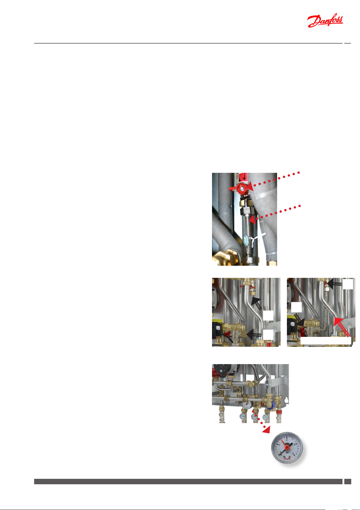
Akva Lux II VX with ll valve
(placed on the DHW pipe (see product introduction page 3), built-in
from factory (photo 1)).
This type of substation does not include a permanent water lling pipe, but is supplied with a exible water lling pipe, which
is supplied loose (may be attached to the ll valve as shown
on enclosed photo 1), and which must be mounted on site as
shown on photo 3.
1
Fill valve
Filling pipe
The pump must be switched o when lling the system with water.
• Demount the plugs M1 and M2 on HE supply and DHW (photo
2) and mounting the exible pipe as shown on photo 3).
• Mount the exible water lling pipe and open the ball valves
for the HE supply and return ow as well as the ball valve for
DCW.
• Carefully open the ll valves V1 and V2 and ll the system with
water and at the same time vent the system.
• Fill the heat exchanger / the system with water* until the ma-
nometer shows a working pressure, which corresponds to the
system height + approx. 5 m (approx. 1.2 - 1.5 bar).
• Close the ll valves, demount the pipe and remount the plugs
M1 and M2 (remember gaskets).
• Finally open the remaining ball valves and heat up the sy-
stem.
• After lling and heat-up of the system it should be vented by
means of the air vents on the substation, if any and on the radiators.
• For substations, which include zone valve, remember to re-
move the red split on the position indicator of the zone valve.
• Then switch on the pump.
2 3
V2
V1
M2
M1
Water lling pipe
Manometer
Danfoss District Energy VI.GP.Q3 .02 DKDHR
1717
Page 18

Instructions for installation and use Akva Lux II VX substations
Akva Lux II VX without ll valve
Filling of water to the heating system must be done outside the
substation, typically by connection to a cold water supply in the
household installation.
The pump must be switched o when lling the system with
water.
• Open the ball valves for the HE supply and return ow and ll
the system with water and at the same time venting the system.
• Fill the heat exchanger / the system with water until the manometer shows a working pressure, which corresponds to the
system height + approx. 5 m (approx. 1.2 - 1.5 bar).
• Finally open the remaining ball valves and heat up the system.
• After lling and heat-up of the system it should be vented by
means of the air vents on the substation, if any and on the radiators.
• For substations, which include zone valve, remember to remove the red split on the position indicator of the zone valve.
• Then switch on the pump.
Manometer and lling
If the pressure drops below 1 bar, water must be added to the system.
The operating pressure should never exceed 1.5 bar.
(The safety valve opens at 3 bar)
If system pressure drops dramatically within a short time, heating
system should be examined for leakage, - this includes checking
the factory set pressure of the expansion vessel.
Rell line (option)
If water needs to be added to the system a rell line is applicable
on some markets, if in accordance with all local regulations, please check with your heating supplier.
The rell line includes a pressure reducing valve type 11 BIS, which
will open, when the ow/pressure on the secondary side drops.
The pressure adjusting valve is adjustable and is supplied pre-set
at 3 bar.
The rell line with pressure reducing valve can be mounted in top
or bottom of the substation.
- Mount the rell line
- Open the ball valves
18
DKDHR VI.GP.Q3.02 Danfoss District Energy
Page 19

Instructions for installation and use Akva Lux II VX substations
9.0 Recirculation connection
If the household piping system features domestic hot water
recirculation, the substation must be connected to the recirculation
system. The circulation set for recirculation connection is not standard
equipment. The set must be purchased as extra equipment.
We recommend establishing recirculation BEFORE mounting the
substation on the wall.
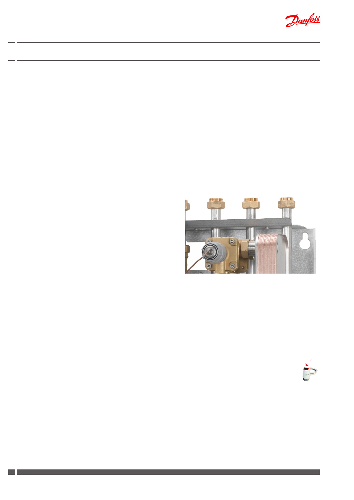
Connect the recirculation pipe from the xed household piping to
the hexagon nipple at the bottom of the substation, - see photo to
your right .
You must always t a pump and a non-return valve to the recirculation pipe, with ow direction towards the substation.
(This is not part of the delivery and must be mounted on site).
If a time-controlled pump is used, we recommend setting of the
circulation water temperature to approx. 35°C.
Please note that if the circulation pump (outside the substation) is
stopped for a protracted period, we recommend that the bypass
thermostat is shut o for the same period.
The circulation set and and control change from bypass to DHW
recirculation will be described thoroughly on page 21.
Danfoss District Energy VI.GP.Q3 .02 DKDHR
1919
Page 20

Instructions for installation and use Akva Lux II VX substations
9.1 Installation instructions - recirculation
A1
A2
B
E
D
C2
Please note that this circulation set applies to substations with
4 as well as 6 mm capillary tube.
Therefore excess components may occur and we ask you please to
ignore these.
You must always t a pump and a non-return valve to the recirculation pipe, with ow direction towards the susbstation. (This is not
part of the delivery and must be mounted on site).
Fig. 1+ 2
In substations, equipped with ECL controller, it may be necessary to
remove the actuator in order to prepare the substation for connection to the recirculation system.
Disassemble in points 1, 2 and 3, and move actuator and pipe section
to the left (g. 1).
If it is necessary to create additional space loosen nut 4 (g. 2) by the
bypass valve, allowing it to be turned to right.
(Please note that the above instructions serve as guideline only, as substation execution
may vary and therefore variants with another component placement may be supplied).
B1
C1
1
2
4
3
Fig. 1 Fig. 2
Fig. 3 Fig. 4
C
C
Then follow below instructions and nish by mounting the actuator
and pipe section and possibly bypass valve again. Remember gaskets!
Fig. 3
Demount nipples/plugs (6 mm Allen Key) from controller.
Fig. 4
Mount circulation hose end A1 and nipple B in controller (for substatios with 6 mm capillary tube nipple B1 is to be mounted.
Fig. 5
Demount capillary tube from T-piece (Pos C).
Fig. 6
Plug the hole in pos. C with 4 mm screw plug C1 (substation with 4
mm capillary tube) or with union nut and ball plug C2 (substations
with 6 mm capillary tube).
Fig. 7
Fit the capillary tube end from pos. C in nipple B (alternatively B1
for 6 mm capillary tube) in DHW controller by means of union nut
and cutting ring.
Fig. 5 Fig. 6
Fig. 7 Fig. 8
Fig. 8
Fix circulation hose end A2 and hexagon nipple E in mounting
plate as shown.
20
DKDHR VI.GP.Q3.02 Danfoss District Energy
Page 21
Instructions for installation and use Akva Lux II VX substations
7369316-0 SIBC VI.CB.T1.6K © Danfoss 05/03 1
Instructions
10.0 Description of the Akva Lux II VX variants
10.1 Akva Lux II VX (thermostatic control) - 1 HE circuit and instantaneous domestic hot water heater
Substation for indirect heating for single-family, semi-detatched
and terraced houses as well as ats. With one heating circuit for
radiator or oor heating and with instantaneous water heater for
domestic hot water heating. For wall-mounting and with variable
connection possibilities.
The HE supply temperature is controlled by a self-acting thermostat thermostat T°C 200.
Please note:
Your substation may look dierent than the substation shown,
as variants with other components may be supplied.
Instructions for the tted components will be supplied together
with the substation.
Dierential pressure controller
(Standard on systems with self-acting thermostat).
The dierential pressure controller reduces the high unctuations
in pressure in the district heating network, ensuring constant operating pressure across the substation
possible operating conditions for radiator thermostats, which ena
bles individual control of the room temperature.
and thereby ensures the best
-
Dierential pressure controller AVPL
AVPL is a self-acting dierential pressure controller for PN 16 with
adjustable dierential pressure setting. Der AVPL keeps a constant
dierential pressure even with a variable system resistance.
The AVPL can be set at any dierential pressure between 0,05 bar
and 0,25 bar. The preset factory setting of the controller is 0,1 bar.
To alter the dierential pressure, use an Allen Key NV 3.
1 full turn is equivalent to approx. 0.01 bar. The arrow on the controller top shows that the setting of the dierential pressure is increased
when it is turned clockwise and reduced when turned counter-clockwise. The controller settings can be changed in accordance with the
enclosed producer instructions.
Dierential pressure controller (PN 16) AVPL
Return mounting, adjustable setting.
AVPL 1.0/1.6
1 5
2 6
34 7
r kPa
20 25
19 24
18 23
17 22
16 21
15 20
14 19
13 18
12 17
11 16
10 15
9 14
8 13
7 12
6 11
5 10
49
38
27
16
05
Alternative dierential pressure controller TD200
Alternatively a diferential pressure controller type TD200 can be
mounted in the substation.
This type of dierential pressure controller is preset from factory and
should not be adjusted afterwards.
AVPL
Danfoss District Energy VI.GP.Q3 .02 DKDHR
2121
Page 22

Instructions for installation and use Akva Lux II VX substations
Control of heating circuit
The temperature for the heating circuit is controlled by a thermostatic valve T°C 200.
Approximate thermostat scale setting for range 25-70° C:
Pos. 2 = 30°C
3 = 40°C
4 = 50°C
5 = 60°C
6 = 70°C
Please note that the values are intended as a guide and may vary
according to the district heating operating conditions.
Approximate supply temperatures at:
10 °C outdoor temperature approx. 40°C
0 °C outdoor temperature approx. 55°C
-10 °C outdoor temperature approx. 65°C
Please note that a label on the thermostatic valve will indicate the
temperature range.
It is important to keep the supply temperature to the radiators as low
as possible (the temperature is indicated by thermometer mounted
in HE return). The room temperature is controlled by radiator thermostats.
Floor heating (substation with heat exchanger for oor heating)
It is important to keep the supply temperature to the oor heating
system as low as possible, approx. 30-35° (the temperature is indicated by thermometer mounted in HE return),
The T°C is typically set in pos. 2-2.5 (intended as a guide). The supply
temperature should not exceed 40°C
(ALWAYS refer to the instructions of the oor supplier)
Alternatively the HE temperature is controlled by a self-acting temperature controller Danfoss AVTB. The controller has a control valve,
thermostatic actuator and handle for temperature setting. The thermostatic actuator consists of a bellows, capillary tube and sensor.
The AVTB closes on rising temperature.
The thermostat will be set by the installer in connection with the commissioning, but it may be necessary to adjust it subsequently depending on the outdoor temperature.
Approximate thermostat scale settings:
1.0 = 35 °C
1.5 = 45 °C
2.0 = 55 °C
2.5 = 65 °C
3.0 = 75 °C
Other variations with other types of thermostatic valves for control
of the heating circuit may occur.
Circulation pump, heating circuit
See item 11 on page 37 for more information about circulation
pump.
AVTB
22
DKDHR VI.GP.Q3.02 Danfoss District Energy
Page 23

Instructions for installation and use Akva Lux II VX substations
088R0248| 15.12.2005 | Version 03
VI.SB.H3.02 12-2005 Produced by Danfoss Industri Service 05.09 JJ-Bi.DS
Electronic programmable room thermostat (option)
As an option the Akva Lux II VX with thermostatic control can be
delivered with a zone valve, which enables connection to an elec-
tronic programmable room thermostat.
The thermal actuator of the zone valve is switched on by an external contact from the room thermostat, and starts to open or close
the valve. The actuating movement is achieved by means of an
electrically heated expansion element. When the heating current is
switched o, the actuator shuts or opens the valve.
The actuator is equipped with a visual position indicator to show
the open or closed position of the valve.
INSTRUCTIONS
TWA NC
TWA-A
For Danfoss RA valves
TWA-V
For Danfoss RAV/VMT valves
TWA-L
For Danfoss RAVL valves
TWA-K
For Heimeier/MNG/Oventrop
valves with M30 × 1.5 connection,
generally as per attached drawing.
Other valves must be veried
individually to ensure correct
valve closing measurement and
valve top geometry.
TWA-D
For Danfoss RTD valves
*) 24 V Class II transformer (SELV)
**) 230 V max. 3 A pre-fuse
If the substation is connected to a room thermostat the temperature is controlled by the room thermostat and radiator thermostats.
Please note that the room thermostat keeps the temperature at a
constant level in the whole apartment according to the set room
parameters.
Consult additional maintenance instructions for room thermostat
for further information. It is recommended to avoid fully opened
thermostats on some radiators and fully shut-o on others. Higher
temperature at the top and lower temperature at the bottom part
of radiators means that the system operation is correct. To keep correct temperature and friendly microclimate for human beings in the
apartment, it is recommended to ensure regular airing in rooms.
Rell line (option)
A district heating rell line is applicable on some markets.
See page 19 for more detailed description.
Danfoss District Energy VI.GP.Q3 .02 DKDHR
2323
Page 24

Instructions for installation and use Akva Lux II VX substations
7369316-0 SIBC VI.CB.T1.6K © Danfoss 05/03 1
Instructions
10.2 Akva Lux II VX (thermostatic control and optional juntion box + zone valve) - 1 HE circuit and instantaneous DHW heater
Substation for indirect heating for single-family, semi-detatched
and terraced houses as well as ats. With one heating circuit for
radiator or oor heating and with instantaneous water heater for
domestic hot water heating. For wall-mounting and with variable
connection possibilities.
The HE supply temperature is controlled by a self-acting thermostat thermostat T°C 200.
Please note:
Your substation may look dierent than the substation shown, as variants with other components may be supplied.
Supplier instructions for the tted components will be supplied together
with the substation.
Dierential pressure controller
(Standard on systems with self-acting thermostat).
The dierential pressure controller reduces the high unctuations
in pressure in the district heating network, ensuring constant operating pressure across the substation
possible operating conditions for radiator thermostats, which ena
bles individual control of the room temperature.
and thereby ensures the best
-
Dierential pressure controller AVPL
AVPL is a self-acting dierential pressure controller for PN 16 with
adjustable dierential pressure setting. Der AVPL keeps a constant
dierential pressure even with a variable system resistance.
The AVPL can be set at any dierential pressure between 0,05 bar
and 0,25 bar. The preset factory setting of the controller is 0,1 bar.
To alter the dierential pressure, use an Allen Key NV 3.
1 full turn is equivalent to approx. 0.01 bar. The arrow on the controller top shows that the setting of the dierential pressure is increased
when it is turned clockwise and reduced when turned counter-clockwise. The controller settings can be changed in accordance with the
enclosed producer instructions.
Dierential pressure controller (PN 16) AVPL
Return mounting, adjustable setting.
AVPL 1.0/1.6
1 5
2 6
34 7
r kPa
20 25
19 24
18 23
17 22
16 21
15 20
14 19
13 18
12 17
11 16
10 15
9 14
8 13
7 12
6 11
5 10
49
38
27
16
05
Alternative dierential pressure controller TD200
Alternatively a diferential pressure controller type TD200 can be
mounted in the substation.
This type of dierential pressure controller is preset from factory and
should not be adjusted afterwards.
AVPL
24
DKDHR VI.GP.Q3.02 Danfoss District Energy
Page 25

Instructions for installation and use Akva Lux II VX substations
Control of heating circuit
The temperature for the heating circuit is controlled by a thermostatic valve T°C 200.
Approximate thermostat scale setting for temperature range 35-85°C:
Pos. 2 = 45°C
3 = 55°C
4 = 65°C
5 = 75°C
Please note that the values are intended as a guide and may vary
according to the district heating operating conditions.
It is important to keep the supply temperature to the radiators as low
as possible (the temperature is indicated by thermometer mounted
in HE return). The room temperature is controlled by radiator thermostats.
Please note that a label on the thermostatic valve will indicate the
temperature range.
Circulation pump, heating circuit
See item 11 on page 36 for more information about circulation
pump.
Electronic programmable room thermostat (option)
As option the Akva lux II with thermostatic control can be delivered
with a zone valve and junction box, as shown in the photo on page
24. This enables connection to an electronic programmable room
thermostat.
The thermal actuator of the zone valve is switched on by an external contact from the room thermostat, and starts to open or close
the valve. The actuating movement is achieved by means of an
electrically heated expansion element. When the heating current is
switched o, the actuator shuts or opens the valve.
The actuator is equipped with a visual position indicator to show
the open or closed position of the valve.
If the substation is connected to a room thermostat the temperature is controlled by the room thermostat and radiator thermostats.
Please note that the room thermostat keeps the temperature at a
constant level in the whole apartment according to the set room
parameters.
Consult additional maintenance instructions for room thermostat
for further information. It is recommended to avoid fully opened
thermostats on some radiators and fully shut-o on others. Higher
temperature at the top and lower temperature at the bottom part
of radiators means that the system operation is correct. To keep correct temperature and friendly microclimate for human beings in the
apartment, it is recommended to ensure regular airing in rooms.
Danfoss District Energy VI.GP.Q3 .02 DKDHR
2525
Page 26

Instructions for installation and use Akva Lux II VX substations
Electrical junction box
The electrical junction box houses the internal electrical connections
of the substation and allows the wiring in the substation to interface
with the main power supply provided by a local utility.
For the Akv Lux II VX with junction box, the pump and zone valve are
pre-wired to the junction box, and the junction box is also prepared
for connection of a room thermostat.
In case of oor heating a safety switch is also connected in the junction
box, securing that zone valve and pump will close in case of overheating.
See enclosed wiring diagram for more information.
Rell line (option)
A district heating rell line is applicable on some markets.
See page 19 for more detailed description.
26
DKDHR VI.GP.Q3.02 Danfoss District Energy
Page 27
Instructions for installation and use Akva Lux II VX substations
DH-SMT/DK VI.KT.F2.02 © Danfoss 06/2008
$2!&4
Instructions
ECL Comfort 110
Application 116
Constant temperature control
of domestic hot-water systems (DHW)
User guide,
Installation & Maintenance
7369316-0 SIBC VI.CB.T1.6K © Danfoss 05/03 1
10.3 Akva Lux II VX (ECL110) - 1 HE circuit and instantaneous DHW heater
Substation for indirect heating for single-family, semi-detatched
and terraced houses as well as ats. With one heating circuit for
radiator or oor heating and with instantaneous water heater for
domestic hot water heating. For wall-mounting and with variable
connection possibilities.
The temperature for the heating circuit is controlled by a Danfoss
ECL controller in combination with an electronic actuator. The ECL
controller acts as the brain of the heating system. It lets you easily
control and optimise system performance and operation.
Please note:
Your substation may look dierent than the substation shown,
as variants with other components may be supplied.
Supplier instructions for the tted components will be supplied
together with the substation.
Heating circuit
The temperature for the heating circuit is controlled by the Danfoss
ECL controller. The supply temperature is calculated by the controller on basis of the outdoor temperature.
The factory-setting of the controller ensures that heating is automatically switched o in the summer period.
In periods with higher heat demand the controller settings can be
changed in accordance with the enclosed producer instructions for
the mounted controller.
Installation & Maintenance
Danfoss ECL Comfort 110
Dierential pressure controller AVPL
AVPL is a self-acting dierential pressure controller for PN 16 with
adjustable dierential pressure setting. Der AVPL keeps a constant
dierential pressure even with a variable system resistance.
The AVPL can be set at any dierential pressure between 0,05 bar
and 0,25 bar. The preset factory setting of the controller is 0,1 bar.
To alter the dierential pressure, use an Allen Key NV 3.
1 full turn is equivalent to approx. 0.01 bar. The arrow on the controller top shows that the setting of the dierential pressure is increased
when it is turned clockwise and reduced when turned counter-clockwise. The controller settings can be changed in accordance with the
enclosed producer instructions.
Dierential pressure controller (PN 16) AVPL
Return mounting, adjustable setting.
Instructions
AVPL 1.0/1.6
1 5
2 6
r kPa
20 25
19 24
18 23
17 22
16 21
15 20
14 19
13 18
12 17
11 16
10 15
9 14
8 13
7 12
6 11
5 10
49
38
27
16
05
AVPL
34 7
Danfoss District Energy VI.GP.Q3 .02 DKDHR
2727
Page 28

Instructions for installation and use Akva Lux II VX substations
INSTRUCTIONS
065R9075
Control of heating circuit
For control of the heating circuit the Akva Lux II VX (ECL 110) is supplied with a 2-way valve VS 2 and an electrical actuator AMV 150,
which in combination with the ECL controller controls the heating
circuit.
The electrical actuator has undergone a functional test from factory.
In case of operating disturbances the actuator can be closed by turning the manual operation knob on top of actuator counter-clockwise.
Please see enclosed instructions,
Electrical actuator AMV 150
2-way valve VS 2
Manual operation (AMV 150)
VS2 2-way
DN L (mm)
15 65
20 70
25 75
DN L1(mm)
15 131
20 142
25 159
DN L2(mm)
15 139
20 154
25 159
Instructions
AMV 150
065R9075
AMV 150 + AMV 150 + AMV 150 +
VS2 (DN 15) VMV AVQM (DN 15)
Actuators for three point control AMV 150 www.danfoss.com Page 2
ENGLISH
Motorer til 3-punkts styring AMV 150 www.danfoss.dk Side 3
DANSK
Stellantriebe für 3-Pkt.- Eingangssignal AMV 150 www.danfoss.de Seite 3
DEUTSCH
Motor för 3-punktsreglering AMV 150 varme.danfoss.se Sida 4
SVENSKA
Servomotor met 3-puntssturing AMV 150 www.danfoss.nl Pagina 4
NEDERLANDS
Pavaros trijų padėčių valdymui AMV 150 www.danfoss.lt 5 puslapis
LIETUVIŲ K.
Motori trīs punktu kontrolei AMV 150 www.danfoss.com Lpp. 5
LATVISKI
Szelepmozgatók hárompontos szabályozáshoz AMV 150 www.danfoss.com 6. oldal
MAGYAR
Servopohony s tříbodovým regulačním signálem AMV 150 www.danfoss.cz Strana 6
ČESKY
Siłowniki sterowane sygnałem 3-punktowym AMV 150 www.danfoss.pl Strona 7
POLSKI
Электроприводы для трехпозиционного регулирования AMV 150
DN L3(mm)
15 69
20 74
25 79
РУССКИЙ
www.danfoss.ru Стр аниц а 7
VS2
Press and hold the button (on
the bottom side of the actuator)
during manual operation.
Option
As alternative to the AVPL dierential pressure controller and the
2-vay valve VS 2 the Akva Lux II VX (ECL 110) can be supplied with
a self-acting ow controller with integrated control valve Danfoss
AHQM, for control of the heating circuit.
In this case instructions for the AHQM will be enclosed.
Safety function (option)
In case of oor heating the oor heating circuit can as an option be
supplied with a safety thermostat Jumo AT and an electrical actuator AMV 13 instead of AMV 150 for protection against overheating.
,QVWUXFWLRQV
$09
5
$099096 $09$940 $099%
'+6076, (,+'DQIRVV
5
1
1
AHQM
AMV 13
28
DKDHR VI.GP.Q3.02 Danfoss District Energy
Page 29

Instructions for installation and use Akva Lux II VX substations
Circulation pump, heating circuit
See item 11 on page 36 for more information about circulation
pump.
Rell line (option)
A district heating rell line is applicable on some markets.
See page 19 for more detailed description.
Danfoss District Energy VI.GP.Q3 .02 DKDHR
2929
Page 30
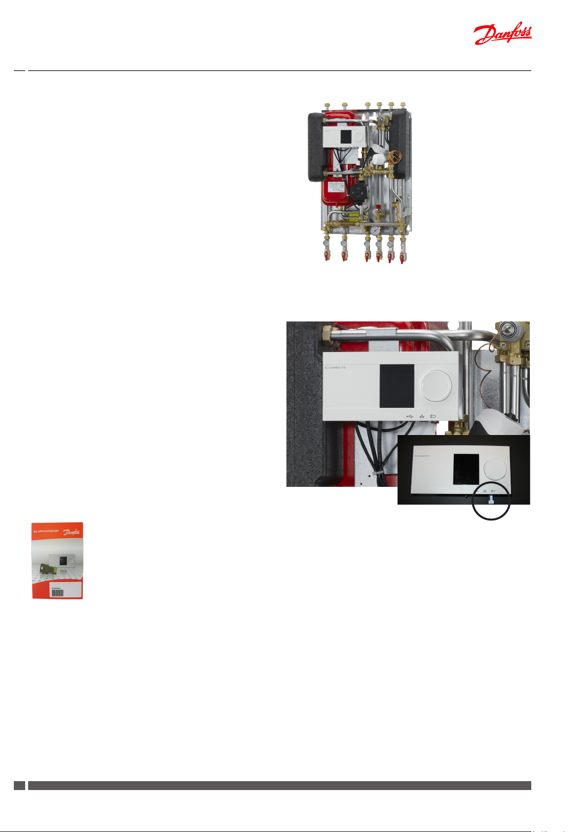
Instructions for installation and use Akva Lux II VX substations
10.4 Akva Lux II VX HWP (ECL 210/A237)
Substation for indirect heating for single-family, semi-detatched
and terraced houses as well as ats. With one heating circuit for
radiator or oor heating and with instantaneous water heater for
domestic hot water heating. For wall-mounting and with variable
connection possibilities.
The temperature for the heating circuit is controlled by a Danfoss
ECL controller in combination with an electronic actuator. The ECL
controller acts as the brain of the heating system. It lets you easily
control and optimise system performance and operation.
Please note:
Your substation may look dierent than the substation shown,
as variants with other components may be supplied.
Supplier instructions for the tted components will be supplied
together with the substation.
Heating circuit
The temperature for the heating circuit is controlled electronically by
the Danfoss ECL controller. The supply temperature ist calculated by
the controller on basis of the outdoor temperature.
The ECL Comfort 210 controller is loaded with a selected application
by means of an ECL Application Key (Plug-&-Play). The Application
Key contains information about application, languages and factory
settings.
Various applications can be loaded by means of the ECL Application
Key, and it is possible to update the controller with new application
software.
The controller is factory preset to turn o the heating automatically
in the summer period.
The controller settings can be changed in accordance with the enclosed producer instructions for the mounted controller.
See ECL Application Key Box with ECL Comfort 210/310 user guide
and mounting guide, for further information.
We also refer to Danfoss Installation Guide für ECL Comfort 210, application
A230, which can be found on www.heating.danfoss.com
ECL application key
30
DKDHR VI.GP.Q3.02 Danfoss District Energy
Page 31

Instructions for installation and use Akva Lux II VX substations
Control of heating circuit
For controlling the heating circuit the Akva Lux II VX HWP is supplied
with a self-acting ow controller with integrated control valve Danfoss
AHQM and an electrical actuator AMV 150, which in combination
with the ECL controller controls the heating circuit.
The controller closes when set max. ow is exceeded.
The ow-controller is equipped with excess pressure safety valve,
which protects the actuator from too high dierential pressure.
The electrical actuator has undergone a functional test from factory. In case of operating disturbances the actuator can be closed
manually turning the manual operation knob on top of actuator
counter-clockwise.
Please see enclosed instructions,
Electrical actuator AMV 150
Flow-controller with integrated control valve AHQM
Manual operation (AMV 150)
Instructions
AVQM, AVQMT – PN 16, 25 / DN 15-50
AVQM (PN 16) AVQM (PN 25) AVQMT (PN 25) AVQMT/AVT (PN 25)
DN 15-32 DN 15- 50 DN 32-50 DN 15-5 0 DN 32-50 DN 15-50 DN 32-50
∆p = 0.2 ∆p = 0.2 ∆p = 0.2 ∆p = 0.2 ∆p = 0.2 ∆p = 0.2 ∆p = 0.2
Flow (and temperature) controller with integrated control
ENGLISH
valve AVQM, AVQMT
Flow- (og temperatur-)regulator med indbygget motorventil
DANSK
AVQM, AVQMT
Volumenstrom (und Temperatur-) Regler mit Motorstellventil
DEUTSCH
AVQM, AVQMT
Regulador de caudal (y temperatura) con válvula de control
ESPAÑOL
integrada AVQM, AVQMT
Regulator pretoka (in temperature) z regulacijskim ventilom
SLOVENŠČINA
AVQM, AVQMT
Regulator przepływu (i temperatury) z zaworem
POLSKI
regulacyjnym AVQM, AVQMT
Térfogatáram(és hőmérséklet) szabályozó, motoros
MAGYAR
szabályozó-szeleppel egybeépítve AVQM, AVQMT
Uputstvo AVQM, AVQMT-PN 16, 25/DN 15-50 grejanje.danfoss.com Strana 21
SRPSKI
www.danfoss.com Page 7
www.danfoss.dk Side 9
www.danfoss.de Se it e 11
www.danfoss.es Página 13
www.danfoss.si Stran 15
www.danfoss.pl Strona 17
www.danfoss.hu Oldal 19
Instructions
AMV 150
Actuators for three point control AMV 150 www.danfoss.com Page 2
ENGLISH
Motorer til 3-punkts styring AMV 150 www.danfoss.dk Side 3
DANSK
Stellantriebe für 3-Pkt.- Eingangssignal AMV 150 www.danfoss.de Seite 3
DEUTSCH
Motor för 3-punktsreglering AMV 150 varme.danfoss.se Sida 4
SVENSKA
Servomotor met 3-puntssturing AMV 150 www.danfoss.nl Pagina 4
NEDERLANDS
Pavaros trijų padėčių valdymui AMV 150 www.danfoss.lt 5 puslapis
LIETUVIŲ K.
Motori trīs punktu kontrolei AMV 150 www.danfoss.com Lpp. 5
LATVISKI
Szelepmozgatók hárompontos szabályozáshoz AMV 150 www.danfoss.com 6. oldal
MAGYAR
Servopohony s tříbodovým regulačním signálem AMV 150 www.danfoss.cz Strana 6
ČESKY
Siłowniki sterowane sygnałem 3-punktowym AMV 150 www.danfoss.pl Strona 7
POLSKI
Электроприводы для трехпозиционного регулирования AMV 150
РУССКИЙ
AMV 150 + AMV 150 + AMV 150 +
VS2 (DN 15) VMV AVQM (DN 15)
www.danfoss.ru Стр аниц а 7
Circulation pump, heating circuit
See item 11 on page 36 for more information about circulation
pump.
Safety function (option)
In case of oor heating the oor heating circuit can as an option be
supplied with a safety thermostat Jumo AT and an electrical actuator AMV 13 instead of AMV 150, for protection against overheating.
AHQM
Press and hold the button (on
the bottom side of the actuator)
during manual operation.
,QVWUXFWLRQV
$09
5
$099096 $09$940 $099%
'+6076, (,+'DQIRVV
5
1
1
AMV 13
Rell line (option)
A district heating rell line is applicable on some markets.
See page 19 for more detailed description.
Danfoss District Energy VI.GP.Q3 .02 DKDHR
3131
Page 32

Instructions for installation and use Akva Lux II VX substations
10.5 Akva Lux II VX H2WP (ECL 210/A260) - 2 HE circuits + instantaneous DHW heater
Substation for indirect heating for single-family, semi-detatched
and terraced houses as well as ats. With two heating circuits for
radiator and oor heating and with instantaneous water heater for
domestic hot water heating. For wall-mounting and with variable
connection possibilities.
The temperature for the heating circuit is controlled by a Danfoss
ECL controller in combination with an electronic actuator. The ECL
controller acts as the brain of the heating system. It lets you easily
control and optimise system performance and operation.
Please note:
Your substation may look dierent than the substation shown,
as variants with other components may be supplied.
Supplier instructions for the tted components will be supplied
together with the substation.
Heating circuit
The temperature for the heating circuit is controlled electronically by
the Danfoss ECL controller. The supply temperature ist calculated by
the controller on basis of the outdoor temperature.
The ECL Comfort 210 controller is loaded with a selected application
by means of an ECL Application Key (Plug-&-Play). The Application
Key contains information about application, languages and factory
settings.
Various applications can be loaded by means of the ECL Application
Key, and it is possible to update the controller with new application
software.
The controller is factory preset to turn o the heating automatically
in the summer period.
The controller settings can be changed in accordance with the enclosed producer instructions for the mounted controller.
See ECL Application Key Box with ECL Comfort 210/310 user guide
and mounting guide, for further information.
We also refer to Danfoss Installation Guide für ECL Comfort 210, application
A260, which can be found on www.heating.danfoss.com
ECL application key
32
DKDHR VI.GP.Q3.02 Danfoss District Energy
Page 33

Instructions for installation and use Akva Lux II VX substations
7369311-0 VI.52.D3.003-2005
INSTRUCTIONS
065R9179
Control of heating circuits
For controlling the heating circuit the Akva Lux II VX H2WP is supplied
with a self-acting ow controller with integrated control valve Danfoss
AHQM and an electrical actuator AMV 13, which in combination with
the ECL controller controls the heating circuit.
The controller closes when set max. ow is exceeded.
The ow-controller is equipped with excess pressure safety valve,
which protects the actuator from too high dierential pressure.
The electrical actuator has undergone a functional test from factory.
Please see enclosed instructions,
Electrical actuator AMV 13
Flow-controller with integrated control valve AHQM
Instructions
AVQM, AVQMT – PN 16, 25 / DN 15-50
AVQM (PN 16) AVQM (PN 25) AVQMT (PN 25) AVQMT/AVT (PN 25)
DN 15-32 DN 15- 50 DN 32-50 DN 15-5 0 DN 32-50 DN 15-50 DN 32-50
∆p = 0.2 ∆p = 0.2 ∆p = 0.2 ∆p = 0.2 ∆p = 0.2 ∆p = 0.2 ∆p = 0.2
Flow (and temperature) controller with integrated control
www.danfoss.com Page 7
valve AVQM, AVQMT
Flow- (og temperatur-)regulator med indbygget motorventil
www.danfoss.dk Side 9
AVQM, AVQMT
Volumenstrom (und Temperatur-) Regler mit Motorstellventil
www.danfoss.de Se it e 11
AVQM, AVQMT
Regulador de caudal (y temperatura) con válvula de control
www.danfoss.es Página 13
integrada AVQM, AVQMT
Regulator pretoka (in temperature) z regulacijskim ventilom
www.danfoss.si Stran 15
AVQM, AVQMT
Regulator przepływu (i temperatury) z zaworem
www.danfoss.pl Strona 17
regulacyjnym AVQM, AVQMT
Térfogatáram(és hőmérséklet) szabályozó, motoros
www.danfoss.hu Oldal 19
szabályozó-szeleppel egybeépítve AVQM, AVQMT
Uputstvo AVQM, AVQMT-PN 16, 25/DN 15-50 grejanje.danfoss.com Strana 21
SLOVENŠČINA
ENGLISH
DANSK
DEUTSCH
ESPAÑOL
POLSKI
MAGYAR
SRPSKI
,QVWUXFWLRQV
$09
5
$099096 $09$940 $099%
'+6076, (,+'DQIRVV
5
1
1
Circulation pump, heating circuit
See item 11 on page 36 for more information about circulation
pump.
Control of oor heating circuit
For controlling the oor heating circuit the Akva Lux II VX H2WP is
supplied with a 3-way valve VMV and an electrical actuator AMV
150, which in combination with the ECL controller controls the oor
heating circuit.
AHQM
AMV 13
The electrical actuator has undergone a functional test from factory. In case of operating disturbances the actuator can be closed
manually turning the manual operation knob on top of actuator
counter-clockwise.
Please see enclosed instructions,
Electrical actuator AMV 150
3-way seated mixing valve VMV
NC (normally closed)
RAVK (only VMV DN 15, 20)
ABV - NC
NO (normally open)
ABV - NO
NC (normally closed)
RAVK (only VMV DN 15, 20)
RAVI (only VMV DN 15, 20)
ABV - NC
NO (normally open)
ABV - NO
VMV
065R9179
Instructions
AMV 150
Actuators for three point control AMV 150 www.danfoss.com Page 2
ENGLISH
Motorer til 3-punkts styring AMV 150 www.danfoss.dk Side 3
DANSK
Stellantriebe für 3-Pkt.- Eingangssignal AMV 150 www.danfoss.de Seite 3
DEUTSCH
Motor för 3-punktsreglering AMV 150 varme.danfoss.se Sida 4
SVENSKA
Servomotor met 3-puntssturing AMV 150 www.danfoss.nl Pagina 4
NEDERLANDS
Pavaros trijų padėčių valdymui AMV 150 www.danfoss.lt 5 puslapis
LIETUVIŲ K.
Motori trīs punktu kontrolei AMV 150 www.danfoss.com Lpp. 5
LATVISKI
Szelepmozgatók hárompontos szabályozáshoz AMV 150 www.danfoss.com 6. oldal
MAGYAR
Servopohony s tříbodovým regulačním signálem AMV 150 www.danfoss.cz Strana 6
ČESKY
Siłowniki sterowane sygnałem 3-punktowym AMV 150 www.danfoss.pl Strona 7
POLSKI
Электроприводы для трехпозиционного регулирования AMV 150
РУССКИЙ
AMV 150 + AMV 150 + AMV 150 +
VS2 (DN 15) VMV AVQM (DN 15)
www.danfoss.ru Стр аниц а 7
VMV
Manual operation (AMV 150)
Press and hold the button (on
the bottom side of the actuator)
during manual operation.
Danfoss District Energy VI.GP.Q3 .02 DKDHR
3333
Page 34

Instructions for installation and use Akva Lux II VX substations
Safety temperature monitor
The heating circuits can be supplied with a safety thermostat for
protection against overheating.
Please see enclosed operating instructions
Jumo AT
Circulation pump, oor heating circuit
The oor heating circuit comprises a circulation pump.
See item 11 on page 36 for more information about circulation
pump.
Rell line (option)
A district heating rell line is applicable on some markets.
See page 19 for more detailed description.
34
DKDHR VI.GP.Q3.02 Danfoss District Energy
Page 35

Instructions for installation and use Akva Lux II VX substations
11.0 Circulation pump for HE
Grundfos Pump UPM3 Auto L
Grundfos UPM3 Auto L has 10 optional settings, which can be selected with the push-botton. See g. 1 - User interface.
The user interface is designed with a single push button, one red/
green LED and four yellow LEDs.
The pump is set from factory to Proportional pressure curve 3.
The user interface shows:
* performance view (during operation)
- operation status
- alarm status
* settings view (after pressing the button)
The LEDs show the power consumption for the pump.
When the pump is running, LED 1 is green. The four yellow
LEDs indicate the current power consumption (P1).
See g. 2 - Performance view.
Fig. 1. User interface.
Fig. 2. Performance view.
Fig. 2. Performance view.
Danfoss District Energy VI.GP.Q3 .02 DKDHR
3535
Page 36

Instructions for installation and use Akva Lux II VX substations
Check the pump setting by pressing the button once. The LEDs will
briey show the pump setting before changing back to showing the
power consumption. See g. 3 - Pump settings.
Fig. 3. Pump settings
If the pump setting does not give the desired distribution of heat in
the rooms of the house, change the pump setting. See g. 4 - Re-
commended pump settings.
To change the pump setting, choose the setting you want (see g
3), press the button down for more than 2 seconds (less than 10)
and the LEDs will ash. Then press the button until the LEDs shows
the desired setting. The LEDs ash and when they stop the new setting is saved. The LEDs return to show power cunstumption. Please
note that if the LEDs do not ash after 2 seconds, possibly the pump
setting is locked. To unlock, press the button down for more than 10
seconds. LEDs will ash and the pump is unlocked. To lock the pump,
repeat the procedure.
For more information, see enclosed Grundfos instructions.
grundfos INSTRUCTIONS
UPM3
AUTO L
1
In case the 1
st
LED is red the pump has detected one or more alarms.
See g. 5 - Alarm status. When there is no active alarm anymore
the user interface switches back to operation mode shortly and then
showing power consumption.
Fig. 4. Recommended pump settings
UMP3 15-70 AUTO L
Application Recommended pump mode
Radiator
two-pipe system
Radiator
one-pipe system
Floor heating 1. Constant pressure mode
Ventilation 1. Constant curve mode, speed 1-2-3-4
Domestic hot
water*
Fig. 5. Alarm status
1. Proportional pressure mode
1. Constant curve mode, speed 1-2-3-4
2. Constant pressure mode
2. Constant pressure mode
1. Constant curve mode, speed 1-2-3-4
* Bronze or stainless steel pump housing
36
DKDHR VI.GP.Q3.02 Danfoss District Energy
Page 37

Instructions for installation and use Akva Lux II VX substations
Grundfos Pump UPM3 Auto
Grundfos UPM3 Auto has 12 optional settings, which can be selected with the push-botton. See g. 1 - User interface.
The pump is set from factory to Autoadapt maximum curve proportional pressure.
The user interface shows:
* performance view (during operation)
- operation status
- alarm status
* settings view (after pressing the button)
The LEDs show the power consumption for the pump.
When the pump is running, LED 1 is green. The four yellow
LEDs indicate the current power consumption (P1).
See g. 2 - Performance view.
Fig. 1. User interface.
Fig. 2. Performance view.
Fig. 2. Performance view.
Danfoss District Energy VI.GP.Q3 .02 DKDHR
3737
Page 38

Instructions for installation and use Akva Lux II VX substations
Check the pump setting by pressing the button once. The LEDs will
briey show the pump setting before changing back to showing the
power consumption. See g. 3 - Pump settings.
Fig. 3. Pump settings
If the pump setting does not give the desired distribution of heat in
the rooms of the house, change the pump setting. See g. 4 - Re-
commended pump settings.
To change the pump setting, choose the setting you want (see g
3), press the button down for more than 2 seconds (less than 10)
and the LEDs will ash. Then press the button until the LEDs shows
the desired setting. The LEDs ash and when they stop the new setting is saved. The LEDs return to show power cunstumption. Please
note that if the LEDs do not ash after 2 seconds, possibly the pump
setting is locked. To unlock, press the button down for more than 10
seconds. LEDs will ash and the pump is unlocked. To lock the pump,
repeat the procedure.
For more information, see enclosed Grundfos instructions.
In case the 1
See g. 5 - Alarm status. When there is no active alarm anymore
the user interface switches back to operation mode shortly and then
showing power consumption.
st
LED is red the pump has detected one or more alarms.
Fig. 4. Recommended pump settings
UMP3 15-70 AUTO
Application Recommended pump mode
Radiator
two-pipe system
Radiator
one-pipe system
Floor heating 1. Auto adapt, Constant pressure mode
Ventilation 1. Constant curve mode, speed 1-2-3-4
Domestic hot water 1. Constant curve mode, speed 1-2-3-4
Fig. 5. Alarm status
1. Auto adapt proportional pressure mode
2. Proportional pressure mode **
1. Constant curve mode, speed 1-2-3-4
2. Constant pressure mode **
2. Constant pressure mode **
** factory setting
38
DKDHR VI.GP.Q3.02 Danfoss District Energy
Page 39

Instructions for installation and use Akva Lux II VX substations
12.0 Domestic hot water (DHW)
Description
The domestic hot water is prepared in the heat exchanger based on
the ow principle and the temperature is controlled by a combined
hydraulic and thermostatic self-acting controller PTC2+P with integrated dierential pressure controller, which blocks the ow of
primary and secondary side ow through the heat exchanger immediately after completion of the tapping process.
12.1 Regulation of the domestic hot water temperature
PTC2 controller for domestic hot water (Fig. 1).
Danfoss PTC2 controller for domestic hot water. Adjust the hot water temperature by moving the adjuster lever towards “+” (hotter)
or “-” (colder). Start by turning the lever clockwise – until it stops/
until you cannot turn it any further. Then turn the lever counter-
clockwise until the temperature of the tap water is approx. 48°C
during normal tapping ow (7–8 litres per min.). The temperature
must never exceed 55°C to prevent limescale deposits building up
in the water heater.
Alternative controller PM2+P
As alternative the temperature can be controlled by a the pressure-controlled self-acting controller PM2+P with integrated dierential pressure
controller. Set the DHW temperature by turning the adjuster lever towards red (hotter) or blue (colder). Start by turning the lever clockwise
- until the pin is opposite the blue dot. Then turn the lever counterclockwise until the temperature of the tap water is approx. 48°C during
normal tapping ow (7–8 litres per min.). The temperature must never
exceed 55°C to prevent limescale deposits building up in the water
heater. NB! The pin must be positioned between the blue and red
dot, otherwise the controller will shut down.
12.2 Bypass or circulation thermostat (Fig. 2)
Bypass thermostat (default)
As a standard the substation is equipped with a bypass thermostat,
Danfoss FJVR, so that when water is tapped, the water heater
immediately starts to produce hot water. We recommend setting
of the thermostat in pos.3. If you have to wait a long time (i.e. more
than 20 sec.) for hot water, it may be necessary to set the thermostat
at a higher value.
1
Adjuster lever
Adjuster lever
2
Scale setting (indicative)
Pos. 2 = 30°C
3 = 40°C
4 = 45°C
If you want to avoid waiting time altogether, you will need to set up
domestic hot water recirculation to the tapping points.
Circulation thermostat / conversion to recirculation
If the household piping system features domestic hot water recirculation, the substation must be connected to the recirculation
system.
Conversion to recirculation requires only an additional circulation set.
(this is not part of the delivery and must be purchased as extra equipment, - see photo on page 21).
Connect the recirculation pipe from the xed household piping system
to the hexagon nipple, at the bottom of the substationtion (please
see pages 20 -21 for instructions about how to make recirculation
connection).
If a time-controlled pump is used, we recommend setting the circulation water temperature to approx. 35 °C.
Please note! If the circulation pump (outside the station) is
stopped for a protracted period, we recommend that the bypass
thermostat is shut o for the same period.
Danfoss District Energy VI.GP.Q3 .02 DKDHR
3939
Page 40

Instructions for installation and use Akva Lux II VX substations
13.0 Maintenance
Maintenance work
Is only to be carried out by qualied and authorised personnel.
Inspection
The water heater should be checked regularly by authorised personnel.
Any necessary maintenance must be performed in accordance
with the instructions in this manual and other sets of instructions.
During service the dirt strainers are to be cleaned – including the lter
on the controller, all pipe connections must be tightened and the safety
valve must be function tested by turning the lever.
Rinsing/cleaning of plate heat exchanger
To clean the plate heat exchanger, rinse it by running clean water
through the exchanger at high speed and in the opposite direction to
the normal ow. This will remove any dirt deposits that may have built
up in the exchanger. If rinsing with clean water is not sucient, the
exchanger can also be cleane d by circulating a cleaning agent approved
by Danfoss (e.g. Kaloxi or Radiner Fl cleaning uid) through the
exchanger. Both these cleaning uids are environmentally friendly and
can be disposed o through the standard sewer system. After use of
a cleaning uid, the plate heat exchanger must be rinsed thoroughly
with clean water.
Acid cleaning of plate heat exchanger
Deposits of limesc ale may build up in plate heat exchangers for domestic
hot water on account of the large temperature uc tuations, and because
aerated water is used on the secondary side. If it becomes necessary
to clean the exchanger with acid, this can be done as shown on the
drawing to the right. Brazed plate heat exchangers can withstand
rinsing with a dilute acid solution - e.g. 5% formic, acetic or phosphoric
acid).
Measures after maintenance work
After maintenance work and before commissioning:
– Check that all screwed connections are tight.
– Check that all safet y features, covers, that were removed, have been
replaced properly.
– Clean the working area and remove any spilled materials.
– Clear all tools, materials and other equipment from the working area.
– Connect to energy supply and check for leaks.
– Vent the system.
– Carry out any necessary adjustment again.
– Make sure that all safety features on the device and the system work
properly.
Meter reading
The caretaker/owner must perform visual checking and reading of
the district heating meter at short, regular intervals. (The meter is
not a part of the delivery from Danfoss).
Service procedures must only be performed by trained, authorised
personnel.
NB! Excessive consumption for whatever reason is not covered by
the Danfoss warranty.
Cooling / Return temperature reading
Cooling – i.e. the dierence between the supply and return temperature
of the district heating water – has a signicant eect on overall energy
economy. Therefore, it is important to focus on the supply and return
temperature in the heating system. The dierence should typically be
30–35°C. Please note that a low district heating return temperature is
directly related to the return temperature from the heating circuit and
the return temperature of the circulation water.
It is therefore important to focus on these return temperatures.
40
DKDHR VI.GP.Q3.02 Danfoss District Energy
Page 41

Instructions for installation and use Akva Lux II VX substations
Cooling from the water heater alone:
During tapping, the level of cooling will typically be 30–35°C. When
hot water is not being tapped, it is completely normal for the return
temperature from the water heater to rise slightly. In this situation,
the district heating meter will register very modest consumption as
the volume of water is very small.
On water heaters with recirculation, the calorie meter registers the
heat loss in the circulation pipe.
13.1 Maintenance schedule (recommendations)
Interval Maintenance work Comments
Check all connections for leaks
Check that the safety valve on the cold water supply is
functioning correctly.
Check that all components are intact and functioning as
intended
Clean all dirt lters/strainers in the substation Replace any lters that are not intact
At least once a year
Check that any electrical cables are in serviceable condition
and that it is possible to disconnect the electrical power supply to the substation
Check the pipes and exchanger for signs of corrosion Visual check
Check that the temperature regulators are set in accordance
with the instructions in this manual
Check the functions of all shut-o valves Check that the ball valves open and close as they should
Service and maintenance procedures must only be performed by
trained, authorised personnel.
Please note that after dismantling, the gaskets MUST be replaced.
Once the system has been lled with water, retighten all the pipe
connections once more before performing pressure test for leaks.
After heating of the system, check all the connections and
retighten if necessary.
Please note that the connections may feature EPDM gaskets! Therefore,
it is important that you DO NOT OVERTIGHTEN the pipe
connections. Over-tightening may result in leaks. Leaks caused by
over-tightening or failure to retighten connections are not covered
by the warranty.
If you identify a leak, replace the gaskets and retighten the pipe connections
Check the functionality by turning the lever on the safety valves
In the event of irregularities, lack of functionality or visible faults and
defects in a component, replace the component in questionn
Visual check. Check whether it is possible to disconnect the current to the
substation.
Follow the instructions in the present manual
Danfoss District Energy VI.GP.Q3 .02 DKDHR
4141
Page 42

Instructions for installation and use Akva Lux II VX substations
14.0 Troubleshooting
If operating disturbances occur, the following basic features
should be checked before carrying out acual troubleshooting:
- the substation is correctly connected,
- the district heating supply temperature is at the normal level
(summer at least 60 °C, winter at least 70 °C),
- the dierential pressure is higher than or equal to the normal
(local) dierential pessure in the district heating network. - If
in doubt, ask the district heating plant,
14.1 Troubleshooting - Heating
Problem Possible cause Solution
Dirt strainer clogged on DH og HE side
(radiator circuit).
Filter in district heating meter clogged. Clean the lter (after consulting the
Defective dierential pressure controller. Check the functions of the dierential
Defective sensor Replace sensor.
Defektive actuator. Check the functioning of the actuator.
Defective motor valve - or possibly dirt
in the valve housing.
No heat
Automatic controls wrongly set or defective - possibly power failure.
- the substation is connected to electricity (pump and
automatic components).
- the dirt strainer in the district heating supply pipe is clean,
- air pockets in the system.
Clean dirt strainer.
district heating plant).
pressure controller - clean valve seat if
required.
Check the functions of the motor valve clean valve housing if required.
Check if the setting of the controller is
correct - see separate instructions. Check
the power supply.
Temporary setting of actuator to “manual” control - see instruction on heating
circuit, manual control.
Uneven heat distribution
Supply temperature too high
Pump out of operation.
The pump is set at too low speed of
rotation.
Air pockets in the system. Vent the installation thoroughly.
Air pockets in the system. Vent the installation thoroughly.
Wrong setting of automatic controls. Adjust automatic controls, see instruc-
Defective sensor. Replace sensor.
Defective controller. The controller does
not react as it is should in accordance
with the instructions.
Check that the pump is receiving power
and that it runs. Control that there is
no air in the pump housing - see pump
manual.
Set the pump at higher speed of rotation
- see instructions on heating circuit.
tions for automatic controls.
Call in automatic controls manufacturer
or replace controller.
42
DKDHR VI.GP.Q3.02 Danfoss District Energy
Page 43

Instructions for installation and use Akva Lux II VX substations
Problem Possible cause Solution
Supply temperature too low
Poor cooling
Wrong setting of automatic controls.
Defective controller. The controller does
not react as it is should in accordance
with the instructions.
Outdoor sensor mounted or placed
incorrectly.
Dirt strainer clogged. Clean dirt strainer.
Too small heating surface/ too small
radiators compared to the total heating
requirement of the building.
Poor utilization of existing heating
surface.
The system is single-pipe. It is extremely important to keep the
Adjust automatic controls, see instructions for automatic controls.
Call in automatic controls manufacturer
or replace controller.
Mount/place outdoor sensor correctly.
Increase total heating surface.
Make sure that the heat is distributed
evenly across the full heating surface open all radiators and keep the radiator
in the system from heating up at the
bottom. Higher temperature at the top
and lower temperature at the bottom
part of the radiators means that the
system operation is correct.
supply temperature to the radiators as
low as ever possible, while maintaining a
reasonable level of comfort.
Self-acting thermostat on DH defective
(does not apply to all variants)
Replace thermostat - alternatively only
the sensor.
Danfoss District Energy VI.GP.Q3 .02 DKDHR
4343
Page 44
Instructions for installation and use Akva Lux II VX substations
14.2 Troubleshooting - Domestic hot water
Problem Possible cause Solution
Variations in temperature
Low temperature / variations in temperature at the draining points
Not enough pressure on the hot water
Long waiting time
No domestic hot water Dirt strainer on DH supply clogged. Clean dirt strainer.
Non-return valve on the circulation line
defective (leads to mixing - and the
circulation water pipes become cold du-
Non-return valve in thermostatic mixer
tap in the bathroom defective - leads to
mixing of cold and hot water-. Note that
variations in temperature may occur at
other draining points/water taps in the
household piping!
REMEMBER, to check all the mixer taps in
the house!
Dirt strainer in cold water meter or in the
cold water supply line clogged.
Circulation pump out of operation - (not
part of the dly).
See above.
Replace non-return valve.
Replace mixer tap, or non-return valve
only.
Clean dirt strainer (cold water meter
possibly in consulation with the water
supply company).
Check whether the pump is running whether the pump is receiving power.
Control that there is no air in the pump
housing - see pump manual.
See above.
DHW temperature too low
DHW temperature too high Defective DHW controller.
Declining temperature during tapping
Poor cooling Calied heat exchanger.
Discoloured water (during a protracted
period)
Lack of hot water pressure Calied plate heat exchanger.
Non-return valve on the circulation line
defective (leads to mixing - and the
circulation water pipes become cold during tapping).
Air in capillary tubes.
Calied heat exchanger.
Short-circuiting of / defective heat
exchanger.
Plate heat exchanger short-circuited. Replace the plate heat exchanger.
Replace non-return valve.
Check the functions of the controller,
and replace if required.
Air and rinse capillary tubes.
Clean heat exchanger with acid solution
or replace heat exchanger.
Replace heat exchanger.
Clean heat exchanger with acid solution
or replace heat exchanger.
Replace the plate heat exchanger or
clean it with acid.
44
DKDHR VI.GP.Q3.02 Danfoss District Energy
Page 45

Instructions for installation and use Akva Lux II VX substations
15.0 EU Declaration of Conformity
Danfoss Redan A/S
Telephone +45 87 43 89 43
EC-DECLARATION OF CONFORMITY
For CE marking in EU (European Union)
Danfoss Redan A/S District Energy
DK-8382 Hinnerup
Declares under our sole responsibility that below products including all available power and control options:
Akva Lux II VX
Main components: See instruction manual.
District Energy
Omega 7, Søften
DK-8382 Hinnerup
Covered by this declaration is in conformity with the following directive(s), standard(s) or other normative document(s), provided that the products are used in accordance with our instructions.
EU Directives:
EMC Directive 2004/108/EEC
EN 61000-6-1 2007 Electromagnetic compatibility- Generic standard: Immunity for residential, commercial and light
industry.
EN 61000-6-2 2007 Electromagnetic compatibility- Generic standard: Immunity industry.
EN 61000-6-3 2007 Electromagnetic compatibility- Generic standard: Emission for residential, commercial and light
industry.
EN 61000-6-4 2007 Electromagnetic compatibility- Generic standard: Emission industry.
Machinery Directive 2006/42/EEC
EN ISO 14121-1 Safety of machinery -- Risk assessment
EN 60204-1-Safety of machinery - Electrical equipment of machines — Part 1: General requirements
PED Directive 97/23/EEC
Conformity assessment procedure followed: Module A - Internal control of production
All substations that falls under Article 3 §3 and category 1 shall not be CE-marked according to this directive
CE marked affixed year 2010
Approved by:
Place and date of issue: Hinnerup, Aug. 22nd, 2013
Name: Katja Brødegaard
Title: Quality & HSE Manager
Danfoss District Energy VI.GP.Q3 .02 DKDHR
4545
Page 46

Instructions for installation and use Akva Lux II VX substations
16.0 Commissioning Certicate
Commissioning certicate
The substation is the direct link between the district heating supply network and the household piping system. All supply pipes and the
pipes in the household piping system must be checked and rinsed before commissioning. Once the system has been lled with water, all
pipe connections must be retightened before performing pressure test for leaks. The dirt strainers must be cleaned and the substation
must be adjusted in accordance with the instructions in this manual.
It is important to comply with all technical regulations and the applicable legislation in every respect.
Installation and commissioning must only be performed by trained, authorised personnel.
The substation is checked in the factory for leaks before delivery. Leaks are however possible due to vibrations caused by transport, handling and heating of the system and therefore it is important to check all connections and to retighten if necessarys before commissioning.
Please note that the connections may feature EPDM gaskets! Therefore it is important that you DO NOT OVER-TIGHTEN the connections.
Over-tightening may result in leaks. Leaks caused by overtightening or failure to retighten connections are not covered by the warranty.
To be lled-out by the installer.
This substation has been retightened, adjusted and commissioned
on the: by installer:
Date/Year
Company name (stamp)
46
DKDHR VI.GP.Q3.02 Danfoss District Energy
Page 47

Instructions for installation and use Akva Lux II VX substations
Danfoss District Energy VI.GP.Q3 .02 DKDHR
4747
Page 48

Instructions for installation and use Akva Lux II VX substations
Danfoss Redan A/S · District Energy · Omega 7, Søften · DK-8382 Hinnerup
Tel. +45 87 43 89 43 · Fax: +45 87 43 89 44 · redan@danfoss.com · www.redan.danfoss.dk
VI.GP.Q3.02
Produced by Danfoss Redan A/S © 01/2015
 Loading...