

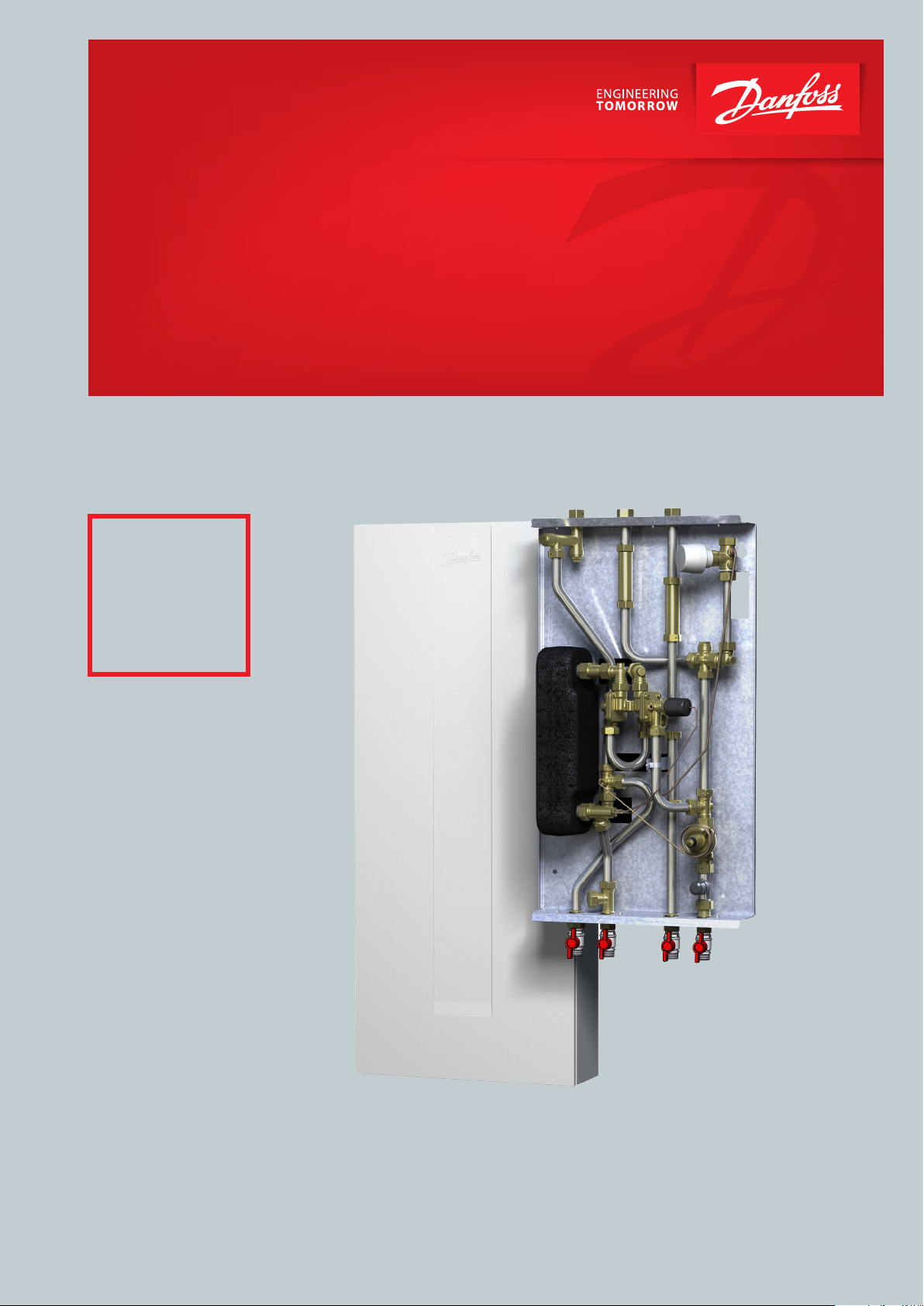
Instructions for installation and use
District heating substation
for exhange of Gas Boilers
Akva Lux II TDP Reno
District district heating substation for heating and domestic hot water.
Reno
Exchange of gas
boilers.
www.danfoss.com
Instructions for installation and use Akva Lux II TDP RENO
1.0 Content
2.0 Product introduction ..............................................................................................................................................................................................................3
3.0 Dimensional sketches / Connections ...............................................................................................................................................................................3
4.0 Enduser instructions, General .............................................................................................................................................................................................4
5.0 Enduser instructions, Initial adjustment/setting ..........................................................................................................................................................5
6.0 Installation instructions, Safety and Handling ..............................................................................................................................................................6
7.0 Getting started .........................................................................................................................................................................................................................7
8.0 Installation instructions, General .......................................................................................................................................................................................8
8.1 Height adjustable cover .............................................................................................................................................................................................. 12
9.0 Adjustment and commissioning of the Akva Lux II TDP RENO ........................................................................................................................... 13
10.0 Maintenance........................................................................................................................................................................................................................... 15
10.1 Maintenance schedule (recommendations) ..................................................................................................................................................... 16
11.0 Troubleshooting, Heating.................................................................................................................................................................................................. 17
12.0 Troubleshooting, Domestic hot water .......................................................................................................................................................................... 18
12.0 EU Declaration of Conformity .......................................................................................................................................................................................... 19
13.0 Commissioning Certicate ................................................................................................................................................................................................ 20
2 | © Danfoss | Produced by Danfoss Redan A/S | 2016.03
VI.JV.R1.02
Instructions for installation and use Akva Lux II TDP RENO
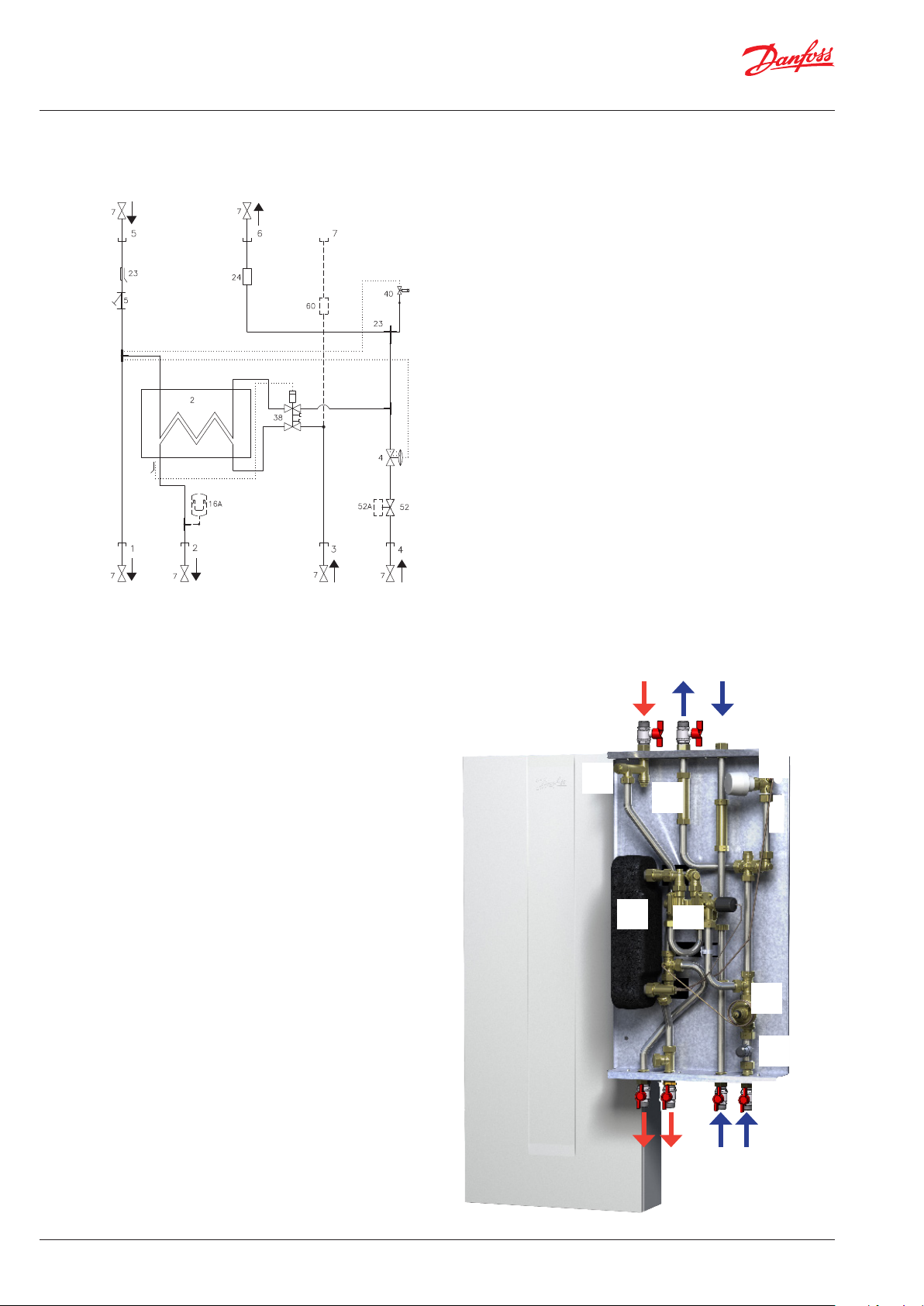
2. PRODUCT INTRODUCTION
DH
Supply
Heating
Supply
DH
Return
2 Plate heat exchanger
4 Dierential pressure controller
Top connection
(DCW connection optional)
5 Strainer
7 Ball valve
23 Sensor pocket for heat meter
24 Fitting piece for heat meter
3/4” x 110 mm
38 PT°C2 controller
40 Danfoss FJVR Thermostat for
Bypass/Circulation
52 Zone valve Danfoss RA-C
------------------------------------------------Optiones:
16A Anti-hammer vessel CAR19 für TWW
52A Thermo actuator Danfoss TWA-A NC
60 Top connection DCW with DCW tting
piece 3/4” x 110 mm
Accessories:
Ball valve 3/4” x 62 mm ET/ET
Bottom connection
Heating
KWWW
Return
2 Plate heat exchanger DHW
4 Dierential pressure controller
5 Strainer
7 Ball valve
23 Sensor pocket for heat meter
24 Fitting piece for heat meter
38 PTC2+P controller
40 Danfoss FJVR thermostat for Bypass/Circulation
52 Zone valve Danfoss RA-C
60 Top connection DCW with tting piece for cold water meter
3/4” x 110 mm (optional)
Please note that the cover is adjustable by 100 mm in height.
Please refer to page 12 for more information.
Please note:
Your substation may look dierent than the substation shown,
as variants with other components may be supplied.
The control function, however, is basically as stated in this
instruction manual.
Instructions for the tted components will be supplied together
with the substation.
Primary
Return
DCW connection
Top (optional)
Primary
Supply
60
40
5
24
2
38
4
52
7
Connections size:
DH, HE, DHW, DCW: G¾” IT
3 | © Danfoss | Produced by Danfoss Redan A/S | 2016.03
HE
Supply
DHW
DCW
HE
Return
VI.JV.R1.02
Instructions for installation and use Akva Lux II TDP RENO
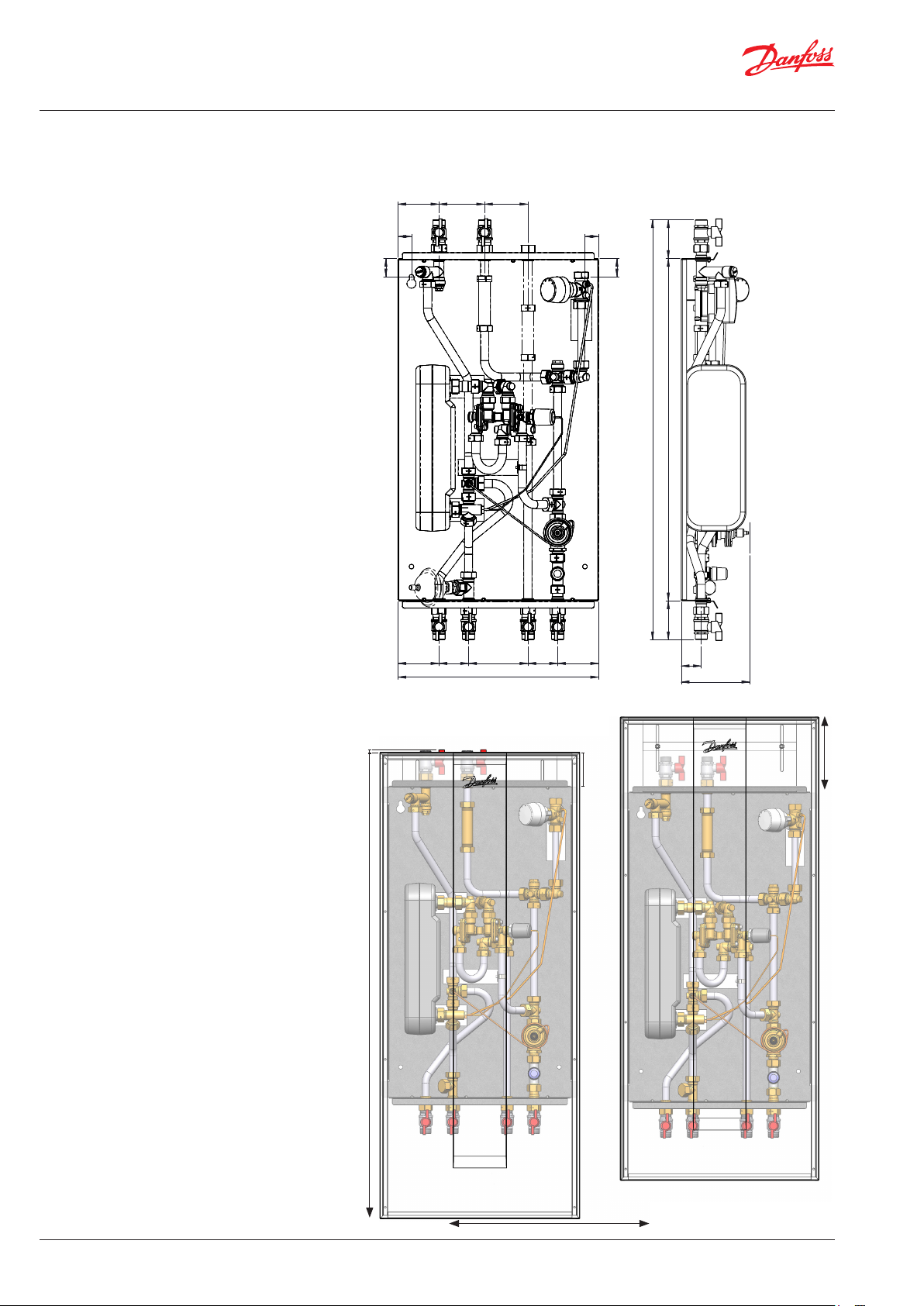
3. ADIMENSIONAL SKETCHES - CONNECTIONS
Connections:
1 Heating (HE) Supply, bottom
2 Domestic hot water (DHW), bottom
3 Domestic cold water (DCW) bottom
4 Heating (HE) Return
5 District heating (DH) Supply, top
6 District heating (DH) Return, top
7 DCW connection, top (option)
Depth incl. of mounting plate:
150 mm
Connections size:
DH, HE, DHW, DCW: G¾” IT
5 6 7
90 100 95
30 30
40
85
40
920
85 750
Dimensions:
Without cover:
H 920 x W 440 x D 150 mm
With cover:
H 1130/1140 x W 480 x D 150 mm
Please note that the cover is adjustable
by 100 mm in height.
Please refer to page 12 for more information.
90 65 130 65 90
440
1 2 3 4
10 mm
1130 mm
44
150
180 mm
80 mm
4 | © Danfoss | Produced by Danfoss Redan A/S | 2016.03
480 mm
VI.JV.R1.02
Instructions for installation and use Akva Lux II TDP RENO
4. ENDUSER INSTRUCTIONS, GENERAL
Instructions
Please read these instructions carefully.
The manufacturer accepts no liability for loss or damage resulting from
failure to comply with these instructions. Read and follow these instructions carefully to prevent the risk of physical injury and/or damage to
property. Exceeding the recommended operating parameters appreciably increases the risk of personal injury and/or damage to property.
Installation, commissioning and maintenance must be carried out
by qualied and authorised personnel (both plumbing and electrical
work).
Once the station has been installed and is operating, there is nor-
mally no need to alter the settings or other functions. The district
heating substation is very reliable and easy to operate.
If necessary, you can change the temperature settings as described
on page 8. For more detailed information about the substation, see
the sections concerning installation and commissioning.
Description
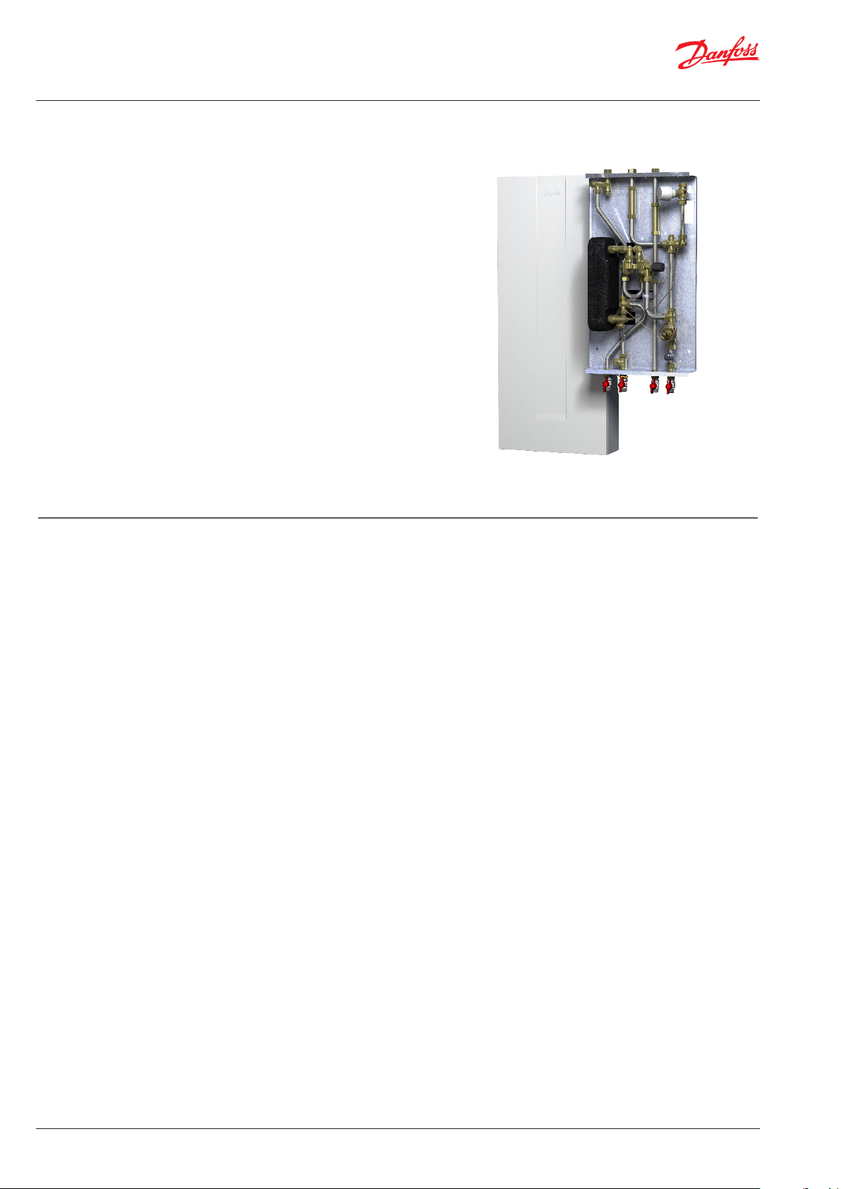
These instructions apply to substation Type Akva Lux II TDP RENO,
which ist a district heating substations, which is especially designed
for the exchange of gas boilers in single-family, semi-detached and
terraced houses as well as ats. With one heating circuit and instantaneous water heater for domestic hot water heating.
Akva Lux II TDP RENO substations are tted with a dierential pressure
controller that maintains a constant pressure in the heating circuit(s).
The supply temperature to the radiators is always identical to the district heating supply temperature. The room temperature is adjusted
solely using the radiator thermostats.
Akva Lux II TDP RENO is designed for wall mounting. For this purpose
it is tted with a height-adjustable cover made of white painted sheet
steel. The existing connections for DHW and DCW as well as supply
and return of secondary heating circuits can be used without major
changes, but it is recommended that the connections for the primary
hot water ow and return are to lead through the chimney. Optionally
the cold water supply can also be connected from above.
As further option it is possible to install a water hammer vessel to
dampen the pressure strokes.
Cooling from the water heater alone:
During tapping, the level of cooling will Typeically be 30–35°C. When
domestic hot water is not being tapped, it is completely normal for
the return temperature from the water heater to rise slightly. In this
situation, the district heating meter will register very modest consumption as the volume of water is very small.
On substations with recirculation, the heat meter registers the heat
loss in the recirculation pipe.
Irregularities
When reading the meters, check all joints and connections for leaks.
If you identify any irregularities/leaks, contact your professional
provider for assistance.
Check the troubleshooting section before contacting your
professional provider.
Warning! Hot surfaces
Parts of the substation may be very hot and can cause burn injuries. Be very careful when you are in the immediate vicinity of
the unit.
Warnings about high pressure and high temperature
The maximum supply temperature in the district heating network can be up to 90°C and the operating pressure can be up
to 10 bar. This may result in a risk of scalding from touching the
substation and from outow of the medium (water/steam). Exceeding the substation design data and operating parameters for
pressure and temperature carries an appreciable risk of personal
injury and/or damage to property.
Emergencies
In the event of re, leaks or other hazards, immediately shut o
all sources of energy to the substation, if possible, and call for
appropriate assistance.
If the domestic hot water is discoloured or malodorous, shut o
We recommend regular inspections of the substation - ideally in connection with readings of the district heating meter.
Pay special attention to any leaks and an excessively high return temperature in the district heating circuit (poor cooling of the district heating water). Cooling – i.e. the dierence between the supply and return
temperature of the district heating water – has a signicant eect on
the overall economy. Therefore, it is important to focus on the supply
and return temperature in the heating system.
The dierence should Typeically be 30–35°C in systems that operate
with radiators. In systems that feature oor heating, the dierence is
Typeically 5–10°C. In these systems, it is important that the supply
temperature does not exceed 35°C.
Please note that a low district heating return temperature is directly
related to the return temperature from the heating/oor heating circuit
and the return temperature of the domestic hot water recirculation (in
systems with domestic hot water recirculation). It is therefore important
to focus on these return temperatures..
VI.JV.R1.02
© Danfoss | Produced by Danfoss Redan A/S | 2015.10 | 5

Instructions for installation and use Akva Lux II TDP RENO
5. Enduser instructions, Initial adjustment/setting
Domestic hot water control
Danfoss PTC2+P controller (Fig. 1) for domestic hot water. Set the
DHW temperature by moving the adjuster lever towards “+” (hotter)
or “-” (colder).
Start by turning the lever clockwise – until it stops/until you cannot
turn it any further. Then turn the lever counter-clockwise until the
temperature of the tap water is approx. 48°C during normal tapping
ow (7–8 litres per min.). The temperature should never exceed 55°C
to prevent limescale deposits building up in the water heater.
Bypass or circulation thermostat
Thermostat (Fig. 2) that keeps the branch pipe warm in the summer
or regulates the circulation temperature if domestic hot water recirculation has been established in the hot water system.
The thermostat should initially be set to position 3.
Heating circuit, Dierential Pressure Controller
The dierential pressure controller (Fig. 4) reduces the high, uctuating pressure in the district heating network to a constant operating pressure. The dierential pressure controller is initially set by the
plumber in connection with the commissioning of the substation.
If disruptions to the operation occur: noise in the radiator thermostats or poor regulation capacity, it may be necessary to reset the
dierential pressure controller to a lower or higher operating pressure. We suggest that you contact your local plumber for assistance
Fig. 1
Handle
Fig. 2
Fig. 3
Heating circuit, temperature control
The room temperature is regulated exclusively using the radiator
thermostats.
AVPL
6 | © Danfoss | Produced by Danfoss Redan A/S | 2016.03
VI.JV.R1.02
Instructions for installation and use Akva Lux II TDP RENO
2. INSTALLATION INSTRUCTIONS, SAFETY AND HANDLING
Instructions
Please read these instructions carefully before installing and comissioning this substation. The manufacturer accepts no liability for loss or
damage resulting from failure to comply with these instructions for use.
Read and follow these instructions carefully to prevent the risk of physical injury and/or damage to peroperty. Exceeding the recommended
operating parameters considerably increases the risk of personal injury
and/or damage to property. Installation, commissioning and maintenance must be carried out by qualied and authorized personnel in
compliance with the local safety regulations.
Once the station has been installed and is operating, there is normally
no need to alter the settings or other functions. The district heating
substation is very reliable and easy to operate.
Energy source
The substation is primarily designed for connection to district heating.
Alternative energy sources can be used if the operating conditions are
equivalent to district heating at all times.
Application
The substation is designed only to operate with water or a water-glycol
mixture (up to 40%), and other heating media may not be used.
The substation is to be connected to the household piping in a frost-free
room, where the temperature does not exceed 50 °C and the relative
humidity is not higher than 80%. The substation must no be covered,
bricked in or otherwise cut o from access.
Choise of materials
Only use materials, that comply with local regulations.
Corrosion
The maximum chloride compounds of the medium must not be higher
than 300 mg/l. The risk of corrosion increases considerably if the recommended chloride content is exceeded.
Safety valve(s)
Installation of safety valve(s) must always be in compliance with local
regulations.
Noise level.
≤ 55 dB.
PTC2+P controller for domestic hot water
The controller is preset from factory and sealed with a
red sticker. This sealing must not been broken.
The warranty becomes void if the sealing is broken.
Connection
It must be possible to cut o all energy sources to the unit - including
electrical connections - at all times.
Potential equalization/grounding
Potential equalization is an electrical equalizing connection to secure
against user contact with dangerous voltage, which may occur for example between two piping systems. Potential equalization reduces
corrosion in heat exchangers, water heaters, district heating substations and plumbing installations. Equalization of potentials should be
eected according to local regulations.
Warning! Hot surfaces
Parts of the substation may be very hot and can cause burn injuries. Be
very careful when you are in the immediate vicinity of the substation.
Warning of high pressure and high temperature
The maximum supply temperature in the district heating network can
be up to 90°C and the operating pressure can be up to 10 bar. This may
result in a risk of scalding from touching the substation and from outow of the medium (water/steam). Exceeding the substation design
data and operating parameters for pressure and temperature carries
an appreciable risk of personal injury and/or damage to property.
Emergencies
In the event of re, leaks or other hazards, immediately shut o all
sources of energy to the substation, if possible and call for appropriate
assistance.
If the domestic hot water is discoloured or malodorous, shut o all ball
valves on the substation, notify all users and call for professional assistance immediately.
Warning of damage during transport
On reception of the substation, and before installing it, check for any
evidence of damage during transport.
The substation must be handled and moved with the greatest care and
attention.
Storage
Before installation, the units must be stored in a dry, heated (i.e. frostfree) room.
(Relative humidity max. 80% and storage temperature 5-70 °C).
The units must not be stacked higher than the limit at the factory (max.
8 layers) Units supplied in cardboard packaging must be lifted using the
handles incorporated in the packaging. Units must be placed on pallets
for transport/moving across large distances.
As far as possible, do not lift the substation by the pipes. Lifting by the
pipes may cause leaks. REMEMBER to retighten.
Disposal
Dispose of the packaging in accordance with the local regulations for
disposal of used packaging materials.
The substation is made of materials that cannot be disposed of together
with household waste.
Close all energy sources and disconnect all connection pipes. Disconnect
and dismantle the product for disposal in accordance with the applicable
local regulations for the disposal of the individual components.
VI.JV.R1.02
IMPORTANT - Tightening of connections
Before adding water to the system, ALL pipe connections MUST be
retightened, as vibrations during transport may have caused leaks.
Once the substation has been lled and the system has been put into
operation, ALL pipe connections MUST be tightened once more.
Handling
We recommend that you wear suitable safety footwear while
handling and installing the substation.
© Danfoss | Produced by Danfoss Redan A/S | 2015.10 | 7
Instructions for installation and use Akva Lux II TDP RENO
7. GETTING STARTED
Connect the substation to the household piping in accordance with
the labelling at the bottom and/or in accordance with the instructions in this manual.
GETTING STARTED is a quick guide and some details in connection with
installation and commissioning may require additional information,
which can be found elsewhere in this instruction manual.
Commissioning:
Please note that the “getting started” quick guide presupposes
that shutt-o possibility is established to and from the substation. - We recommend mounting of ball valves.
1. The substation is prepared for wall mounting. Mount the substation on a solid wall using two sturdy bolts, screws, expansion bolts or similar.
2. Make sure that the ball valves are closed, when connnecting
them to the household piping.
3. Mount the district heating mete (see page 9).
4. IMPORTANT! Tighten all pipe connections, as they may have
loosened during transport and handling.
5. Open the ball valve for the HE supply and return ow and ll
the system with water by carefully opening the ball valve for
the district heating supply ow and at the same time venting
the system. Finally, open the ball valve for the district heating
return ow.
6. Check the substation and the household piping thoroughly
for leaks.
7. Pressure test the entire system for leaks in accordance with
the applicable regulations.
08. Connect automatic components, if any, to the electricity supply, but do not switch on the power.
9. Heat the system and vent the radiator circuit/heating side
thoroughly on the radiators and the air valve, if any.
10. For TDP RENO substations, which include zone valve, remember to remove the red split on the position indicator of the
zone valve.
11. Now switch on automatic components, if any.
12. Finish by adjusting the substation in accordance with this
instruction manuals.
WICHTIG! Erwärmung und Abkühlen der Wohnungsstation
kann Leckagen verursachen. Deshalb kann Nachziehen alle
Verschraubungen und Anschlüsse nach der Inbetriebnahme
notwendig sein.
8 | © Danfoss | Produced by Danfoss Redan A/S | 2016.03
VI.JV.R1.02

Instructions for installation and use Akva Lux II TDP RENO
8. MOUNTING INSTRUCTIONS, GENERAL
The installation, connection and maintenance of the substation must
be performed by qualied and authorised personnel.
Installation must always be performed in accordance with the applicable legislation and in compliance with these instructions.
The substation must be installed so that it is freely accessible and can
be maintained without unnecessary disruption. Lift the substation
by its mounting plate/rear section and secure it to a solid wall using
2 sturdy bolts, screws or expansion bolts positioned in the two keyholes in the mounting plate/rear section.
Before commissioning, rinse all the pipes in the household piping
system thoroughly to remove any impurities, and check and clean
the dirt strainers in the substation.
Connect the substation to the household piping in accordance with
the labelling at the bottom and/or in accordance with the instructions in this manual.
Test and connections
Before lling the system with water, retighten all the pipe connections
because vibrations and shocks during transport and handling may
have caused leaks. Once the system has been lled with water, tighten
all the pipe connections once more before performing pressure test
for leaks. After heating of the system, check all the connections and
retighten if necessary.
Please note that the connections features EPDM rubber gaskets!
Therefore, it is important that you DO NOT OVERTIGHTEN the
union nuts. Over-tightening may result in leaks. Leaks caused by
over-tightening or failure to retighten connections are not covered
by the warranty.
Heat meter, tting pieces.
The substation is equipped with tting pieces for heat meter on
the district heating return line.
Fitting of heat meters
- Close the ball valves on the district heating and the heating
sides.
- Loosen the union nuts at both ends of the tting piece and
remove it.
- Fit the heat meter, - remember to insert gaskets.
- Mount sensor, - remember to insert gaskets.
- After mounting of heat meter remember to check and tighten
all pipe connections before commissioning the substation.
The heat meter consists of ow meter, two temperature sensors for
mounting in DH supply and return and a microprocessor calculator
for the calculation of energy consumption. On the LCD display of the
calculator the energy consumption can be read.
*
VI.JV.R1.02
© Danfoss | Produced by Danfoss Redan A/S | 2015.10 | 9

Instructions for installation and use Akva Lux II TDP RENO
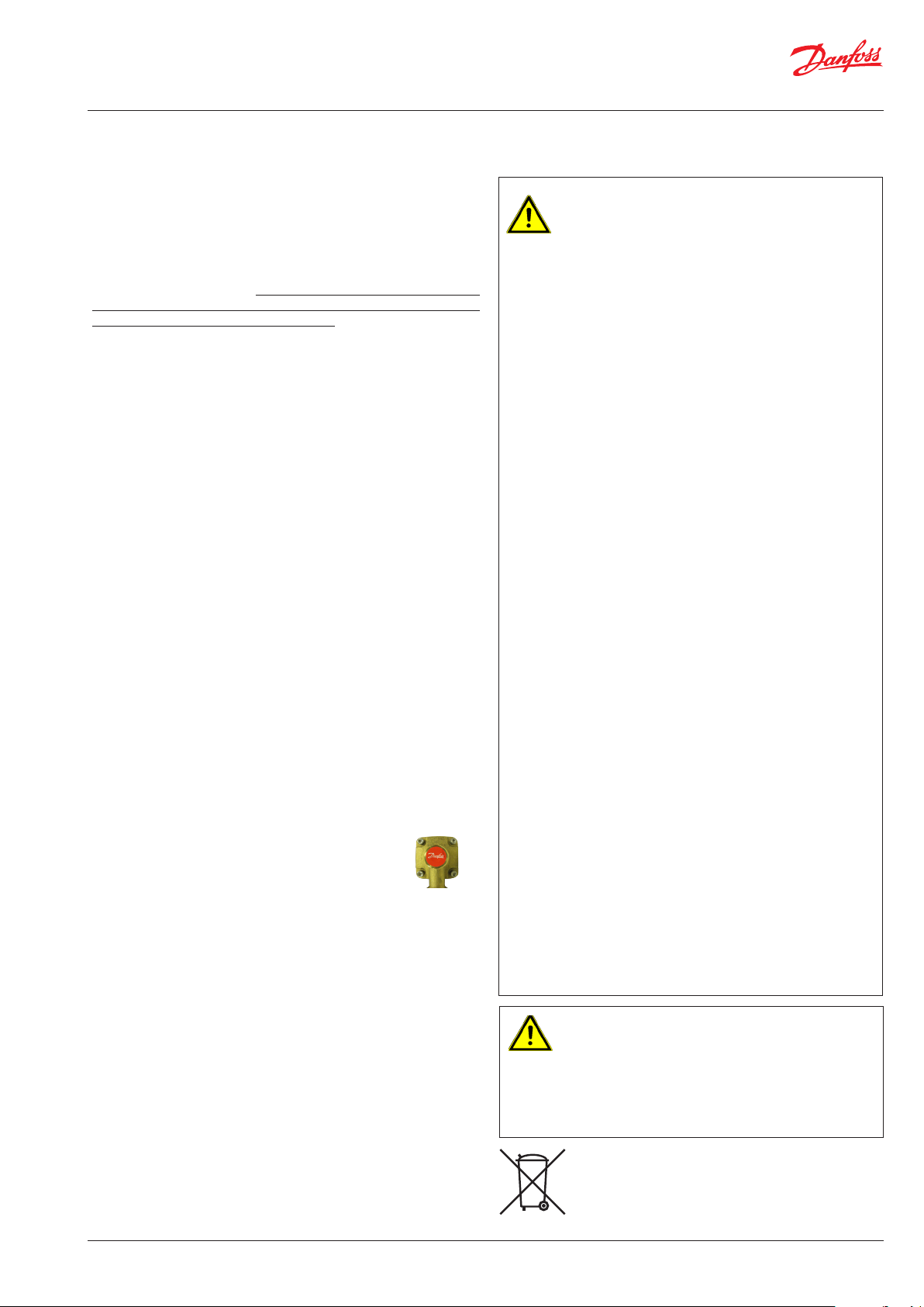
Mounting of temperature sensors
As standard the heat meter is supplied with temperature sensors
for measuring the supply and return ow temperatures.
The Akva Lux II TDP-F at station is prepared for mounting of temperature sensors with M10x1 connection (see photo to the right):
The supply ow sensor is mounted in the sensor pocket on DH
supply (pos A.)
- demount M10 plug (Pos. A)
- insert one temperature sensor in the sensor pocket
- tighten temperature sensor union nut
Mount the return ow sensor in the heat meter housing (pos. B).
A
Cold water meter(s), tting pieces.
The substation is equipped with tting piece(s) for cold water
meter(s).
Fitting of cold water meter(s)
- Close the ball valves on the domestic cold water and the domestic hot water supply.
- Loosen the union nuts at both ends of the tting piece and
remove it.
- Fit the cold water meter, - remember to insert gaskets.
- After mounting of cold water meter remember to check and
tighten all pipe connections before commissioning the cold
water meter(s).
10 | © Danfoss | Produced by Danfoss Redan A/S | 2016.03
VI.JV.R1.02

Instructions for installation and use Akva Lux II TDP RENO
088R0248| 15.12.2005 | Version 03
VI.SB.H3.02 12-2005 Produced by Danfoss Industri Service 05.09 JJ-Bi.DS
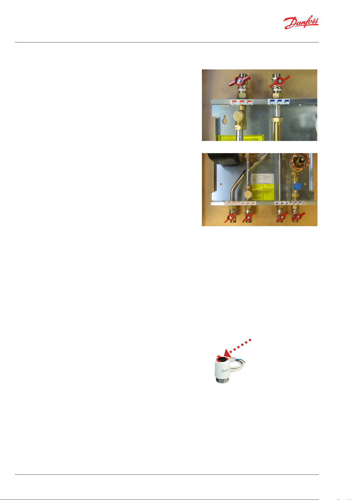
Zone valve / thermal actuator TWA-A
The Akva Lux II TDP-F can be supplied with zone valve/thermal actuator TWA-A, which enables connection to an electronic program-
mable room thermostat.
The thermal actuator of the zone valve is switched on by an external contact from the room thermostat, and starts to open or close
the valve. The actuating movement is achieved by means of an
electrically heated expansion element. When the heating current is
switched o, the actuator shuts or opens the valve.
The actuator is equipped with a visual position indicator to show
the open or closed position of the valve.
INSTRUCTIONS
TWA NC
TWA-A
For Danfoss RA valves
TWA-V
For Danfoss RAV/VMT valves
TWA-L
For Danfoss RAVL valves
TWA-K
For Heimeier/MNG/Oventrop
valves with M30 × 1.5 connection,
generally as per attached drawing.
Other valves must be veried
individually to ensure correct
valve closing measurement and
valve top geometry.
TWA-D
For Danfoss RTD valves
*) 24 V Class II transformer (SELV)
**) 230 V max. 3 A pre-fuse
Thermal actuator TWA-V
Please note: Some variants are
supplied with zone valve only, as
illustrated above, and therefore a
thermal actuator TWA-A must be
mounted on the zone valve before connection to an electronic
Electronic programmable room thermostat (option)
If the substation is connected to a room thermostat the temperature is controlled by the room thermostat and radiator thermostats.
Please note that the room thermostat keeps the temperature at a
constant level in the whole apartment according to the set room
parameters.
Consult additional maintenance instructions for room thermostat
for further information. It is recommended to avoid fully opened
thermostats on some radiators and fully shut-o on others. Higher
temperature at the top and lower temperature at the bottom part
of radiators means that the system operation is correct. To keep correct temperature and friendly microclimate for human beings in the
apartment, it is recommended to ensure regular airing in rooms.
Anti-water hammer membrane tank
The station is prepared for connection of an anti-water hammer
membrane tank, which is to be ordered separately.
The anti-water hammer membrane tank is a pressure equalizing tank,
which absorbs the volume changes of the hydraulic uid between
the minimum and maximum temperature to keep us the pressure
largely constant.
If the system is heated, the anti-water hammer membrane tank
absorbs the expansion volume of the water. If system temperature
drops, the anti-water hammer membrane tank leads the expansion
water back into the system. The water pressure in the system remains
constant.
(Please note that the anti-water hammer tank is not included in the
delivery).
VI.JV.R1.02
© Danfoss | Produced by Danfoss Redan A/S | 2015.10 | 11

Instructions for installation and use Akva Lux II TDP RENO
8.1 Height-adjustable cover
The Akva Lux II TDP RENO substations are designed for wall mounting.
Akva Lux II TDP RENO is designed for wall mounting. For this purpose
it is tted with a height-adjustable cover made of white painted sheet
steel.
The cover is adjustable by 100 mm in height, and by oering variable installation possibilities of the cover, installation problems are
prevented.
Figure 1 shows the default position of the cover, by which the cover
is mounted on the mounting plate by means of a plate, which is 80
mm high (see Fig. 1a).
The delivery also includes an extra plate, which can be mounted,
which can be mounted on the existing plate and with this, the cover
can be variably adjusted from 130 to 180 mm in height.
Fig. 1
Plate height 80 mm
Fig. 1a
80 mm 180 mm
Fig. 2
Figure 2 shows the adjustment possibilites with the extra plate.
Figure 2a shows the mounted cover, adjusted to the maximum height.
Plate height 130 mm
Plate heigh 180 mm
Fig. 2a
12 | © Danfoss | Produced by Danfoss Redan A/S | 2016.03
VI.JV.R1.02

Instructions for installation and use Akva Lux II TDP RENO
7369316-0 SIBC VI.CB.T1.6K © Danfoss 05/03 1
Instructions
34 7
9. Adjustment and commissioning of the Akva Lux II TDP RENO
General information
PLEASE NOTE! Some models may have a slightly dierent appearance, but the
control function is in principle the same as described below.
Maintenance and commissioning
Perform maintenance procedures according to the maintenance frequency chart presented in the section entitled “Operation and maintenance”
on pages 15 - 16. Perform adjustment in accordance with the instructions
below.
For cleaning of plate heat exchanger, please see page 15.
Commissioning
Commission the substation in accordance with the instructions on pages 8-14.
Domestic hot water
The domestic hot water is prepared in the heat exchanger based on the
ow principle and the temperature is controlled by a combined hydraulic
and thermostatic self-acting controller PTC2+P (Fig. 1a) with integrated
dierential pressure controller, which blocks the ow of primary and secondary side ow through the heat exchanger immediately after completion of the tapping process.
Regulation of the hot water temperature PTC2+P
Set the DHW temperature by moving the adjuster lever towards “+” (hotter)
or “-” (colder). Start by turning the lever clockwise – until it stops/until you
cannot turn it any further. Then turn the lever counter-clockwise until the
temperature of the tap water is approx. 48°C during normal tapping ow
(7–8 litres per min.).
Fig. 1
Adjuster lever
By-pass function (factory connection).
The Akva Lux II TDP-F substations are supplied with the a Danfoss FJVR bypass thermostat (Fig. 2), so that when water is tapped, the water heater
immediately starts to produce hot water. We re-commend setting of the
thermostat in pos. 3. If you have to wait a long time (i.e. more than 20 sec.)
for hot water, it may be necessary to position the thermostat higher than
pos. 3. If you want to avoid waiting time altogether, you will need to set up
domestic hot water recirculation to the tapping points.
Heating circuit, Dierential pressure controller
The dierential pressure controller (Fig. 3) reduces the high uctuations in
pressure in the district heating network, ensuring constant operating pressure
across the substation.
Dierential pressure controller Type AVPL
The dierential pressure controller is pre-set to 0.1 bar from the factory. To alter
the dierential pressure, use an Allen key – NV3. One full turn is equivalent to
0.01 bar. Turn clockwise to increase the pressure, counter-clockwise to reduce
it.
Recommended setting
Basically, it is recommended to open the controller to its full extent. If disruptions to operation arise, such as noise or uctuations/poor regulation
capacity, it may be necessary to adjust the dierential pressure controller
to a lower operating pressure.
The controller can be adjusted subsequently – see the appendix entitled:
Instructions AVPL 1.0/1.6
Fig.. 2
Fig. 3
Scale setting (indicative)
Pos. 2 = 30°C
3 = 40°C
AVPL 1.0/1.6
1 5
2 6
r kPa
20 25
19 24
18 23
17 22
16 21
15 20
14 19
13 18
12 17
11 16
10 15
9 14
8 13
7 12
6 11
5 10
49
38
27
16
05
VI.JV.R1.02
© Danfoss | Produced by Danfoss Redan A/S | 2015.10 | 13

Instructions for installation and use Akva Lux II TDP RENO
088R0248| 15.12.2005 | Version 03
INSTRUCTIONS
VI.SB.H3.02 12-2005 Produced by Danfoss Industri Service 05.09 JJ-Bi.DS
Electronic programmable room thermostat
The Akva Lux II TDP-F Type 144B2403 is equipped with a zone valve,
and is thereby prepared for tting of a thermal actuator TWA-A,
which enables connection to an electronic programmable room
thermostat.
For Akva Lux II TDP-F Types 144B2434 and 004U8089 zone valve and
thermal actuator are available as an option.
The thermal actuator is switched on by an external contact from
the room thermostat, and starts to open or close the valve. The actuating movement is achieved by means of an electrically heated
expansion element. When the heating current is switched o, the
actuator shuts or opens the valve.
The actuator is equipped with a visual position indicator to show
the open or closed position of the valve.
Please note: Before mounting of
the electronic room thermostat, an
thermal actuator TWA-A for ON/OFF
controls of the heating system must
be mounted on the zone valve.
TWA-A
For Danfoss RA valves
TWA-V
For Danfoss RAV/VMT valves
TWA-L
For Danfoss RAVL valves
TWA-K
For Heimeier/MNG/Oventrop
valves with M30 × 1.5 connection,
generally as per attached drawing.
Other valves must be veried
individually to ensure correct
valve closing measurement and
valve top geometry.
TWA-D
For Danfoss RTD valves
TWA NC
Thermal actuator TWA-A
*) 24 V Class II transformer (SELV)
**) 230 V max. 3 A pre-fuse
If the substation is connected to a room thermostat the temperature is controlled by the room thermostat and radiator thermostats.
Please note that the room thermostat keeps the temperature at a
constant level in the whole apartment according to the set room
parameters.
Consult additional maintenance instructions for room thermostat
for further information. It is recommended to avoid fully opened
thermostats on some radiators and fully shut-o on others. Higher
temperature at the top and lower temperature at the bottom part
of radiators means that the system operation is correct. To keep correct temperature and friendly microclimate for human beings in the
apartment, it is recommended to ensure regular airing in rooms.
14 | © Danfoss | Produced by Danfoss Redan A/S | 2016.03
VI.JV.R1.02

Instructions for installation and use Akva Lux II TDP RENO
10. Maintenance
Maintenance work
Is only to be carried out by qualied and authorised personnel.
Inspection
The water heater should be checked regularly by authorised personnel.
Any necessary maintenance must be performed in accordance
with the instructions in this manual and other sets of instructions.
During service the dirt strainers are to be cleaned – including the lter
on the controller, all pipe connections must be tightened and the safety
valve must be function tested by turning the lever.
Rinsing/cleaning of plate heat exchanger
To clean the plate heat exchanger, rinse it by running clean water through
the exchanger at high speed and in the opposite direction to the normal
ow. This will remove any dirt deposits that may have built up in the
exchanger. If rinsing with clean water is not sucient, the exchanger can
also be cleaned by circulating a cleaning agent approved by Danfoss (e.g.
Kaloxi or Radiner Fl cleaning uid) through the exchanger. Both these
cleaning uids are environmentally friendly and can be disposed o
through the standard sewer system. After use of a cleaning uid, the
plate heat exchanger must be rinsed thoroughly with clean water.
Acid cleaning of plate heat exchanger
Deposits of limesc ale may build up in plate heat exchangers for domestic
hot water on account of the large temperature uc tuations, and because
aerated water is used on the secondary side. If it becomes necessary to
clean the exchanger with acid, this can be done as shown on the drawing
to the right. Brazed plate heat exchangers can withstand rinsing with a
dilute acid sulution - e.g. 5% formic, acetic or phosphoric acid).
Measures after maintenance work
After maintenance work and before commissioning:
– Check that all screwed connections are tight.
– Check that all safety features, covers, that were removed, have been
replaced properly.
– Clean the working area and remove any spilled materials.
– Clear all tools, materials and other equipment from the working area.
– Connect to energy supply and check for leaks.
– Vent the system.
– Carry out any necessary adjustment again.
– Make sure that all safety features on the device and the system work
properly.
Meter reading
The caretaker/owner must perform visual checking and reading of
the district heating meter at short, regular intervals. (The meter is
not a part of the delivery from Danfoss).
Service procedures must only be performed by trained, authorised
personnel.
NB! Excessive consumption for whatever reason is not covered by
the Danfoss warranty.
Cooling / Return temperature reading
Cooling – i.e. the dierence between the supply and return temperature
of the district heating water – has a signicant eect on overall energy
economy. Therefore, it is important to focus on the supply and return
temperature in the heating system. The dierence should Typeically be
30–35°C.
Please note that a low district heating return temperature is directly
related to the return temperature from the heating circuit and the return
temperature of the circulation water.
It is therefore important to focus on these return temperatures.
VI.JV.R1.02
© Danfoss | Produced by Danfoss Redan A/S | 2015.10 | 15

Instructions for installation and use Akva Lux II TDP RENO
Cooling from the water heater alone:
During tapping, the level of cooling will Typeically be 30–35°C. When
hot water is not being tapped, it is completely normal for the return
temperature from the water heater to rise slightly. In this situation,
the district heating meter will register very modest consumption as
the volume of water is very small.
On water heaters with recirculation, the calorie meter registers the
heat loss in the circulation pipe.
Tightening of connections
Retighten all connections after reading of the heat meter. If case of
leaks, contact your professional provider for assistance.
Please note that the connections may feature EPDM rubber gaskets!
Therefore, it is important that you DO NOT OVERTIGHTEN the
union nuts. Over-tightening may result in leaks. Leaks caused by
over-tightening or failure to retighten connections are not covered
by the warranty.
10.1 Maintenance schedule (recommendations)
Interval Maintenance work Comments
If you identify a leak, replace the gaskets and retighten the pipe connections
Check the functionality by turning the lever on the safety valves
In the event of irregularities, lack of functionality or visible faults and
defects in a component, replace the component in question
Visual check. Check whether it is possible to disconnect the current to the
substation.
Visual check. In the event of signs of corrosion, replace pipes or heat
exchanger inconsultance with Danfoss A/S
Follow the instructions in the present manual
At least once a year
Check all connections for leaks
Check that the safety valve on the cold water supply is
functioning correctly.
Check that all components are intact and functioning as
intended
Clean all dirt lters/strainers in the substation Replace any lters that are not intact
Check that any electrical cables are in serviceable condition
and that it is possible to disconnect the electrical power supply to the substation
Check the pipes and exchanger for signs of corrosion
Check that any insulation covers are functioning as intended Check that the insulation ts tightly around the product
Check that the temperature regulators are set in accordance
with the instructions in this manual
Check the functions of all shut-o valves Check that the ball valves open and close as they should
IMPORTANT! Replace gaskets after separation of parts
16 | © Danfoss | Produced by Danfoss Redan A/S | 2016.03
VI.JV.R1.02

Instructions for installation and use Akva Lux II TDP RENO
11. TROUBLESHOOTING - HEATING
If operating disturbances occur, the following basic features
should be checked before carrying out acual troubleshooting:
- the substation is correctly connected,
- the district heating supply temperature is at the normal level
(summer at least 60 °C, winter at least 70 °C),
- the dierential pressure is higher than or equal to the normal
(local) dierential pessure in the district heating network. - If
in doubt, ask the district heating plant,
Problem Possible cause Solution
Dirt strainer clogged on DH or HE side
(radiator circuit.
Filter in district heating meter clogged. Clean the lter (after consulting the
No heat
Uneven heat distribution Air pockets in the system. Vent the installation throughly.
Defective or wrongly set dierential
pressure controller.
Defective room thermostat / actuator Check the funtioning of the room ther-
Air pockets in the system. Vent the installation throughly.
- the substation is connected to electricity (pump and
automatic,
- the dirt strainer in the district heating supply pipe is clean,
- air pockets in the system.
Clean dirt strainer.
district heating plant).
Check the functioning of the dierential
pressure controller - clean valve seat if
required.
mostat / actuator
Supply temperatur too low Dirt strainer clogged Clean dirt strainer
Increase total heating surface
Turn on all the radiators and prevent the
radistors in the system from becoming
Poor cooling
Too small heating surface / too small
radiator in relation to the total heating
requirement of the building
Poor utilization of existing heating
surface
VI.JV.R1.02
© Danfoss | Produced by Danfoss Redan A/S | 2015.10 | 17

Instructions for installation and use Akva Lux II TDP RENO
12. TROUBLESHOOTING - DOMESTIC HOT WATER
Problem Possible cause Solution
Non-return valve on the circulation line
Variations in temperature
Low temperature / variations in temperature at the draining points
defective (leads to mixing - and the
circulation water pipes become cold du-
Non-return valve in thermostatic mixer
tap in the bathroom defective - leads to
mixing of cold and hot water-. Note that
variations in temperature may occur at
other draining points/water taps in the
system!
REMEMBER, to check all the mixer taps in
the house!
Replace non-return valve.
Replace mixer tap, or non-return valve
only.
Not enough pressure on the hot water
Long waiting time
No domestic hot water Dirt strainer on DH supply clogged. Clean dirt strainer.
DHW temperature too low
DHW temperature too high Defective DHW controller.
Dirt strainer in cold water meter or in the
cold water supply line clogged.
Circulation pump out of operation - (not
part of the dly).
See above.
Non-return valve on the circulation line
defective (leads to mixing - and the
circulation water pipes become cold during tapping).
Air in capillary tubes.
Clean dirt strainer (cold water meter
possibly in consulation with the water
supply company).
Check whether the pump is running whether the pump is receiving power.
control that there is no air in the pump
housing - see pump manual.
See above.
Replace non-return valve.
Check the functions of the controller,
and replace if required.
Air and rinse capillary tubes.
Declining temperature during tapping
Poor cooling Calied heat exchanger.
Discoloured water (during a protracted
period)
Lack of hot water pressure Calied plate heat exchanger.
18 | © Danfoss | Produced by Danfoss Redan A/S | 2016.03
Calied heat exchanger.
Short-circuiting of / defective heat
exchanger.
Plate heat exchanger short-circuited. Replace the plate heat exchanger.
Clean heat exchanger with acid solution
or replace heat exchanger.
Replace heat exchanger.
Clean heat exchanger with acid solution
or replace heat exchanger.
Replace the plate heat exchanger or
clean it with acid.
VI.JV.R1.02

Instructions for installation and use Akva Lux II TDP RENO
13. EU DECLARATION OF CONFORMITY
VI.JV.R1.02
© Danfoss | Produced by Danfoss Redan A/S | 2015.10 | 19

Instructions for installation and use Akva Lux II TDP RENO
13. COMMISSIONING CERTIFICATE
The substation is the direct link between the district heating supply network and the household piping system. All supply pipes and the
pipes in the household piping system must be checked and rinsed before commissioning. Once the system has been lled with water, all
pipe connections must be retightened before performing pressure test for leaks. The dirt strainers must be cleaned and the substation
must be adjusted in accordance with the instructions in this manual.
It is important to comply with all technical regulations and the applicable legislation in every respect.
Installation and commissioning must only be performed by trained, authorised personnel.
The substation is checked in the factory for leaks before delivery. Leaks are however possible due to vibrations caused by transport, handling and heating of the system and therefore it is important to check all connections and to retighten if necessarys before commissioning.
Please note that the connections may feature EPDM gaskets! Therefore it is important that you DO NOT OVER-TIGHTEN the connections.
Over-tightening may result in leaks. Leaks caused by ove-rtightening or failure to retighten connections are not covered by the warranty.
To be lled-out by the installer
This substation has been retightened, adjusted and commissioned
on the: by installer:
Date/Year
Company name (stamp)
20 | © Danfoss | Produced by Danfoss Redan A/S | 2016.03
VI.JV.R1.02

Instructions for installation and use Akva Lux II TDP RENO
VI.JV.R1.02
© Danfoss | Produced by Danfoss Redan A/S | 2015.10 | 21

Instructions for installation and use Akva Lux II TDP RENO
22 | © Danfoss | Produced by Danfoss Redan A/S | 2016.03
VI.JV.R1.02

Instructions for installation and use Akva Lux II TDP RENO
VI.JV.R1.02
© Danfoss | Produced by Danfoss Redan A/S | 2015.10 | 23

Danfoss Redan A/S · District Energy · Omega 7, Søften · DK-8382 Hinnerup
Tel. +45 87 43 89 43 · Fax: +45 87 43 89 44 · redan@danfoss.com · www.redan.danfoss.dk
24 | © Danfoss | Produced by Danfoss Redan A/S | 2016.03
VI.IQ.L1.02
 Loading...