How it Works
Log In / Sign Up
Buy Points
How it Works
FAQ
Contact Us
Questions and Suggestions
Users
Danfoss
Loading...
A
AKM
4
AKS
AKS 11
5
AKS 12
4
AKS 2050
3
AKS 21W
AKS 25A
AKS 25D
AKS 25W
AKS 3000
4
AKS 3050
2
AKS 32
4
AKS 32R
3
AKS 33
3
AKS 38
3
AKS 4050
AKS 4100
18
AKS 4100U
19
Aksesuarlar
AKS U 4100
AKV 10
2
AKV 10-n
2
AKV 10P
10
AKV 10PS
10
AKV 15
4
AKV 20
3
AKVA 1
AKVA 10
5
AKVA 10-n
AKVA 15
6
AKVA 20
4
Akva Les
Akva Les II
2
Akva Les II S
Akva Les II TD
Akva Les II VX
AKVA LES II VXe
AKVA LES II VXe Solo
AKVA LES II VXi
2
AKVA LES VXi SOLO
AKVA LES VXi SOLO HOFOR
Akva Lux FSS
Akva Lux FSS AT
Akva Lux II
7
Akva Lux II GW
3
Akva Lux II Reno Eco
2
Akva Lux II S
AKVA LUX II Se
3
Akva Lux II TD
Akva Lux II TDP-F
6
Akva Lux II TDP-F GW
Akva Lux II TDP RENO
3
Akva Lux II VX
12
Akva Lux II VX2
2
Akva Lux II VX2-E
4
Akva Lux II VX2 PTC
Akva Lux II VX3
3
Akva Lux II VX3-E
4
Akva Lux II VX3 PTC
AKVA LUX II VXe
2
Akva Lux II VX H2WP
4
Akva Lux II VX HWP
4
Akva Lux II VXi
7
AKVA LUX II VXi Basis
AKVA LUX II VXi GENTOFTE
Akva Lux II VXi Solo
Akva Lux II VX Series
AKVA LUX II XBS
Akva Lux MSS AT
2
Akva Lux TDP-F
2
Akva Lux VX2
Akva Lux VX2 E
Akva Lux WSS
2
AKVA THERM 22
AKVA THERM 22 WG 28
AKVA THERM 22 WL 28
AKVA THERM 28
AKVA THERM 35
Akva Therm II LV
AKVA THERM LV
2
Akva Vita F
Akva Vita FSS
Akva Vita FSS AT
Akva Vita II
6
Akva Vita II S
2
Akva Vita II TD
2
Akva Vita II TDP-F
2
Akva Vita II VX
2
Akva Vita/Lux FSS
Akva Vita/Lux MSS
Akva Vita/Lux WSS
Akva Vita MSS AT
2
Akva Vita S-F
Akva Vita Special
Akva Vita TDP-F
3
Akva Vita TDP Schacht
Akva Vita TDP Shaft
Akva Vita WSS
2
AKVH 10
4
AKVH 10-n
Loading...
Loading...
Nothing found
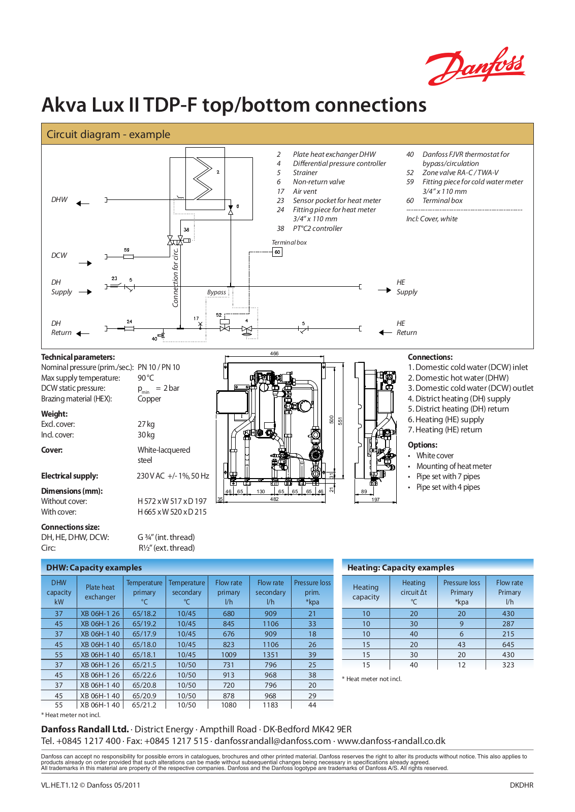
Akva Lux II TDP-F
Fact sheet
2 pgs
643.04 Kb
0
Fact sheet
2 pgs
893.76 Kb
0
Fact sheet [de]
2 pgs
628.15 Kb
0
Fact sheet [de]
2 pgs
1 Mb
0
Installation guide [pl]
4 pgs
3.96 Mb
0
Instructions For Installation And Use Manual
36 pgs
16.16 Mb
0
Table of contents
Loading...
Danfoss Akva Lux II TDP-F Fact sheet
...
Danfoss Fact sheet
Download
Specifications and Main Features
Frequently Asked Questions
User Manual
Download
Loading...
+
hidden pages
Unhide
You need points to download manuals.
1 point = 1 manual.
You can buy points or you can get point for every manual you upload.
Buy points
Upload your manuals
 Loading...