

Page 1
User Guide
Service tool
AK-ST 500
SW Ver. 4.0
Software for operation of AK controller
www.danfoss.com
Page 2

User Guide | Service tool, AK-ST 500
Contents
1. Introduction ....................................................................................................................................................................... 3
2. Principle ............................................................................................................................................................................... 3
3. Prior to installation ..........................................................................................................................................................4
4. How to install the programme .................................................................................................................................... 4
5. Before you start the programme ................................................................................................................................ 5
6. How to start the programme ....................................................................................................................................... 5
7. General navigation .......................................................................................................................................................... 6
8. Configuration of a controller........................................................................................................................................8
9. Authorisation of users .................................................................................................................................................... 9
10. Alarms .................................................................................................................................................................................. 9
11. Log function .....................................................................................................................................................................10
12. Connection to an external system ...........................................................................................................................11
13. Backup ................................................................................................................................................................................12
14. Offline settings ................................................................................................................................................................13
15. Languages ........................................................................................................................................................................13
16. Customer defined texts................................................................................................................................................13
17. Plant overview .................................................................................................................................................................14
18. Update software .............................................................................................................................................................15
© Danfoss | DCS (vt) | 2021.042 | BC173186427013en-000702
Page 3
User Guide | Service tool, AK-ST 500
1. Introduction
2. Principle
AK Service Tool is an advanced tool for operating ADAP-KOOL® refrigeration controllers in a network.
The Service Tool can be used on all AK refrigeration controllers. Some AK controllers have a plug for
direct connection to the Service Tool. All controllers can be operated when they are connected to an
AK System Manager. Individual controllers contain information about the presentation of settings
and measured values. This information is read by the Service Tool the first time it registers a controller
of this type. This information is saved in the Service Tool so that start-up is faster on subsequent
occasions.
In this booklet you are given a brief explanation of the possibilities offered you by AK, both in daily
use and in connection with service calls. The aim is that you are to become familiarised with screen
displays and navigation principles on a general level – so we will not give you an in-depth description
of individual system types or applications.
When you have read the booklet you will be able to derive full benefit of AK-ST 500 as a control and
service tool in your refrigerating plant.
Note: this User Guide is a general introduction to the AK Service Tool. Each controller for a specific
system will furthermore be provided with a separate manual.
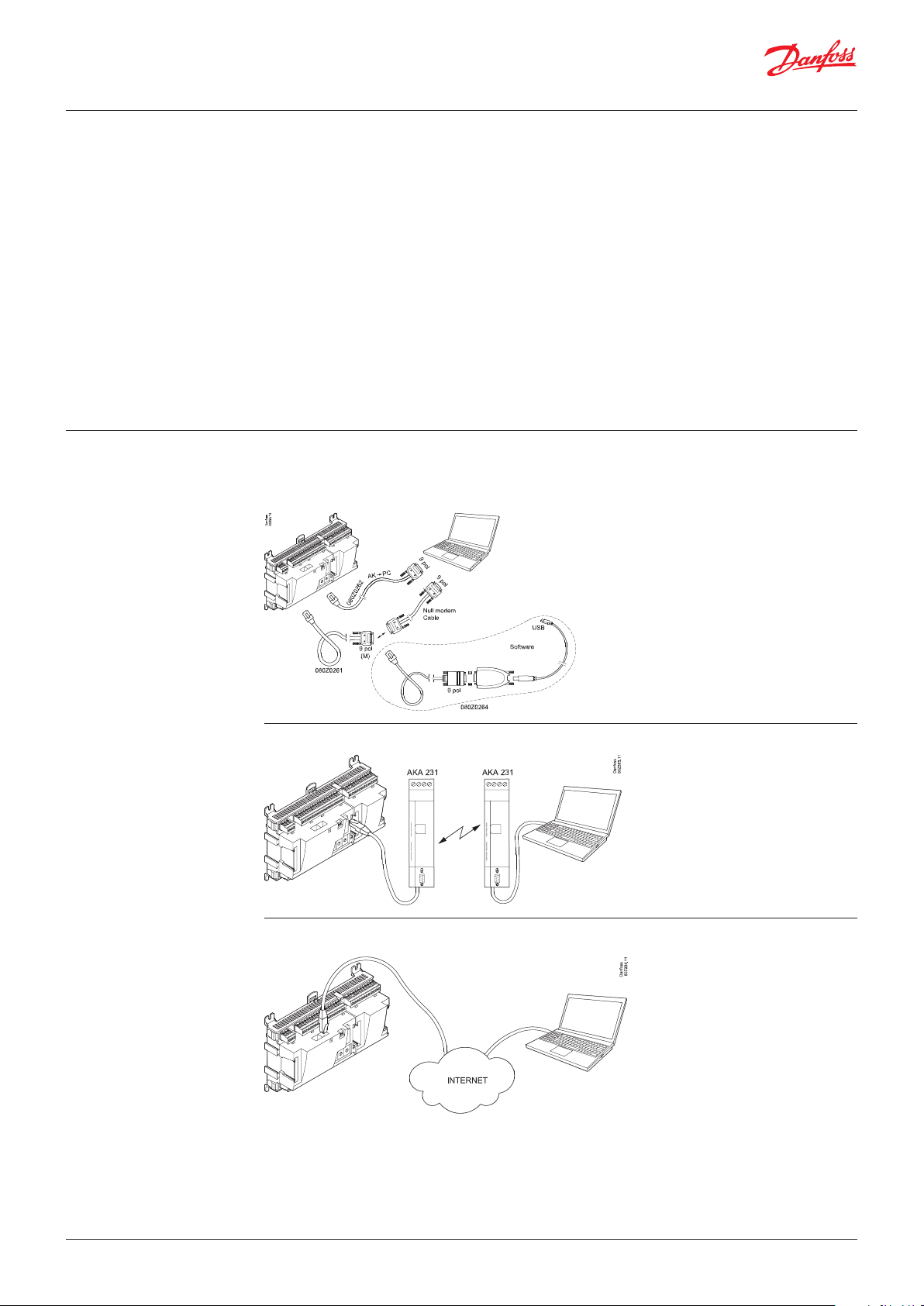
The AK controller is connected to the PC tool where the programme is installed. All settings are
subsequently made via Windows menus.
Direct
Remote via modem
Remote via TCP/IP
© Danfoss | DCS (vt) | 2021.04 BC173186427013en-000702 | 3
Page 4
User Guide | Service tool, AK-ST 500
3. Prior to installation
4. How to install the
programme
Pc requirements:
2.4 GHz Processor, Serial port or USB+converter*
2 GB RAM, 80 GB Harddisk
Software requirements:
Windows 10, 32 bit / 64 bit
Cable:
Cable for connection of AK controller.
Order number: 080Z0261 or 080Z0262.
See the illustrations on previous page.
If a longer cable is required between the controller and the PC a standard RS 232 extension cable can
be inserted. The distance between controller and PC must however not exceed 15 m.
*) Converter: Order no. = 080Z0264
1. In case a previous version is present, please uninstall it before installing the new one. After
Uninstalling, the existing directory of old version of AK-ST 500 installed before will still be present.
Do not delete or remove the folder and its contents. It should be left the same.
2. Download the installer file from: https://www.danfoss.com/en/service-and-support/downloads/
dcs/adap-kool-software/ak-st-500/
3. Run the installation file. Follow the instructions on the screen
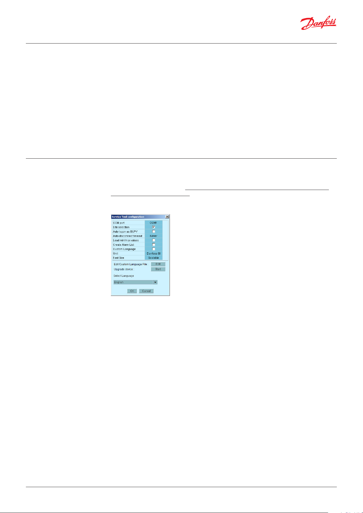
4. After the installation a configuration of the program must be made.
• COM port: Indicate the COM port to be used for the direct connection.
• Site selection: If you want the option of connecting to the system via a modem or TCP/IP, this must
be selected. This means that ”site selection” will appear so that you can select system.
• Auto logon as SUPV: Select this option if you want automatic login with the ”SUPV” user profile.
• Auto disconnect: Service Tool closes automatically if idle for the set time. Service Tool closes
automatically if idle for the set time.
• Load min/max values: Should only be selected if you expect to use offline programming.
Uploading takes time. The Service Tool will read and save setting limits for the controllers you
connect to.
• Create alarm list: Generates an alarm list for later use. Name = Alarms.XML
• Custom Language: By marking this function, the program will use texts that are written in the file
“Custom Language”. See later on in the text.
• Unit: Select unit. (Bar and °C, or Psi and °F)
• Font size: Choose size or let it be scalable
• Edit Custom Language file: This function gives you access to change texts for selected functions.
Read more on page 13.
• Upgrade device: Use only if the software in the connected controller needs to be updated. Read more
on page 15.
• Select language: Must be set for the language you wish to use.
If the controllers contain the selected language, this language will be dominant on the operating
controllers. If not, English will be shown.
© Danfoss | DCS (vt) | 2021.044 | BC173186427013en-000702
Page 5
User Guide | Service tool, AK-ST 500
5. Before you start the
programme
1. Connect controller and PC
Or to the network via the System Manager, if applicable.
6. How to start the
programme
2. Switch on the controller if it is not already switched on.
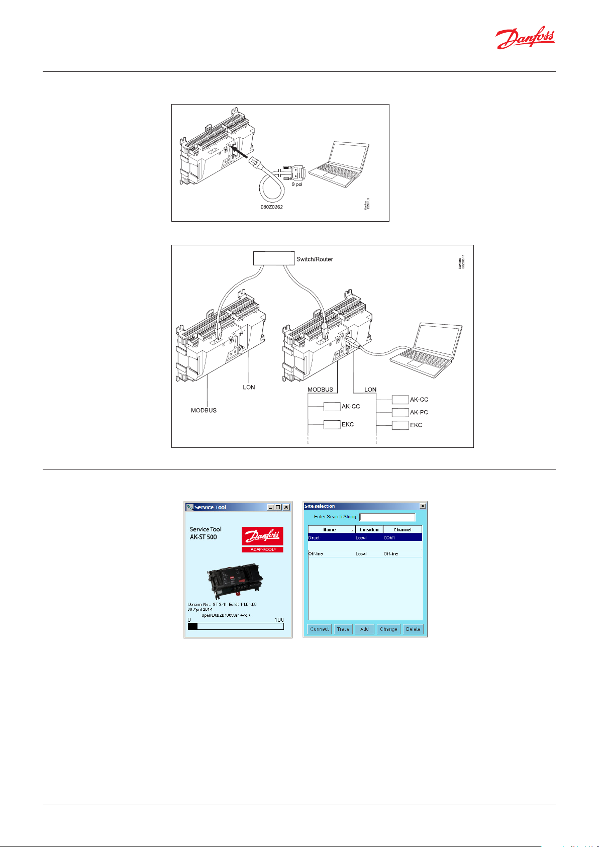
1. Via the Start menu move to “Service Tool”
(In the PC the application is found in the “ADAP-KOOL” folder)
2. Select ”Direct” when the PC is connected directly to a controller.
(Later there may be several lines where you can select connections to other systems, e.g. via
modem or TCP/IP connection.)
3. Press ”Connect”
When the programme encounters a new controller for the first time, a file will be downloaded to
the PC. This transaction will take a couple of minutes. You can follow the transfer on the bar at the
bottom of the screen.
4. Select user level
The various user levels range from “seeing only” to carrying out installation and setup of the plant.
There is an overview on page 8. The user name with the greatest powers is from the “SUPV” factory
(super user).
© Danfoss | DCS (vt) | 2021.04 BC173186427013en-000702 | 5
Page 6
User Guide | Service tool, AK-ST 500
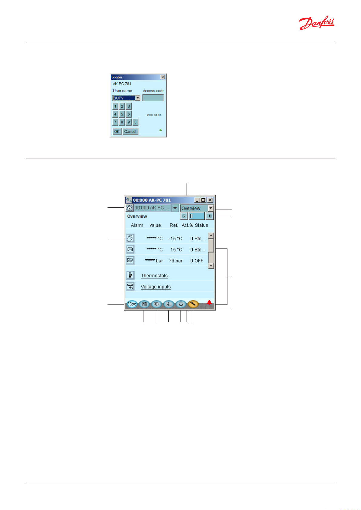
5. Logon
The first time you start the programme, use the “123” pass- code. This code has been put in by the
factory and can be used on all user levels until it is changed.
Note: when you are in contact with the controller it is the relevant controller’s data and setting
options that have to be operated. They are described in separate manuals.
7. General navigation Here you will get an impression of what a controller’s control panel looks like. The icons vary according
to the controller switched on. But generally the operating blocks are as shown here:
1
2
3
4145 6 7 8 9
1. Communication and system functions
You have the following options:
• Disconnecting
• Changing user profile
• Viewing communication log
• Update group name (see page 14)
13
12
11
10
And if you are connected to a System Manager:
• Backing up all units on the network
• Copying set-up from a file to a unit
• Printing settings for all or selected units on the network
• Network overview
2. One of the controllers functions
Each key gives access to data concerning the regulation and possibility of adjusting it. When you have
received the required information/adjusted the parameters, you can click your way down to another
level and obtain a similar access.
3. Back to survey
The key at the button left takes you right back to the shown overview display.
© Danfoss | DCS (vt) | 2021.046 | BC173186427013en-000702
Page 7

User Guide | Service tool, AK-ST 500
4. Day/night schedule
Here you can read and set the individual controller’s operating performance on a weekly basis. You
can also consider deviations in connection with Sundays and holidays.
5. Manual operation
Here you start and stop the automatic regulation.
6. Log function
Here you obtain an overview of the operation viewed from two angles:
• Historically: what has transpired in a given period for selected parameters.
• Trends: shows how the plant is operating here and now – useful data, for example, for tuning of the
7. Alarms
Here you have a list of active and cancelled alarms, respectively. See also page 9.
8. System unit only
Setting for plant controls (Master control functions)
9. Configuration
Gives you access to the configuration element – See page 8.
10. Communication
When you are logged on, a green “lamp” indicates that you are online with the controller. If this
for some reason is not the case, the lamp will be red. A yellow lamp indicates that AK2 is trying
to establish the connection. When an alarm bell is shown, there is an active alarm on the actual
controller.
system to energy-optimal operation or change of application.
11. Alarm bell
Shows that there is an active alarm that needs handling.
Asterisks (***) at a measurement indicates that the signal is defective.
12. Page navigation
When you reach the underlying pages to the overview display you will in many cases encounter a
page navigation option: +/- keys where you can change page when the settings are divided up on
several parallel pages (the page you are on is marked with a dark column among the light ones).
13. Regulation navigation
Having selected a controller you can via the “drop down” select from which part of the regulating
range you wish to download/adjust data.
14. Network address
Here you can see the controller’s address and name on the network.
You can also connect to one of the other controllers on the network.
© Danfoss | DCS (vt) | 2021.04 BC173186427013en-000702 | 7
Page 8

User Guide | Service tool, AK-ST 500
8. Configuration of a
controller
Screw spanner
Via the function key to the extreme right (with screw spanner icon) you leave the Daily User section
of the controller. Instead you now move into the Service User section reserved for installers/ service
engineers who either have to configurate a controller or carry out basic changes of the existing
configuration.
The “screw spanner” leads you to a menu with regulation-specific items for configuration of the
application to be controlled.
The number of menu items will adapt
itself to the application, so that only
the relevant menus are visible.
The following items of the menu are always shown, whatever the plant type:
Lock/unlock configuration
Here you lock important settings so that the setup will not be changed by a mistake. Unlock if you
want to change in the configuration.
System setup
Here you set the clock and name the controller.
Select plant type
Here you find all the functions and setups that define the plant. There are usually several input angles
to the different regulating functions.
I/O configuration
With this function you define the signals there have to be on the different inputs and outputs.
I/O status and manual
Here you can see status and values of the individual inputs and you can carry out manual override of
the output signals.
Authorisation
Here users and passwords are defined. The factory settings are as follows:
Profile User Read Write Password
Dail Daily All No 123
Serv Service All Adjust values 123
Supv Super user All All 123
Backup/restore
Enables you to make a backup of a controller’s settings, either with a view to transferring them from
a replaced controller to a new one or to making “copy paste” of a controller’s settings to new/other
controllers with the same code number and software version.
© Danfoss | DCS (vt) | 2021.048 | BC173186427013en-000702
Page 9
User Guide | Service tool, AK-ST 500
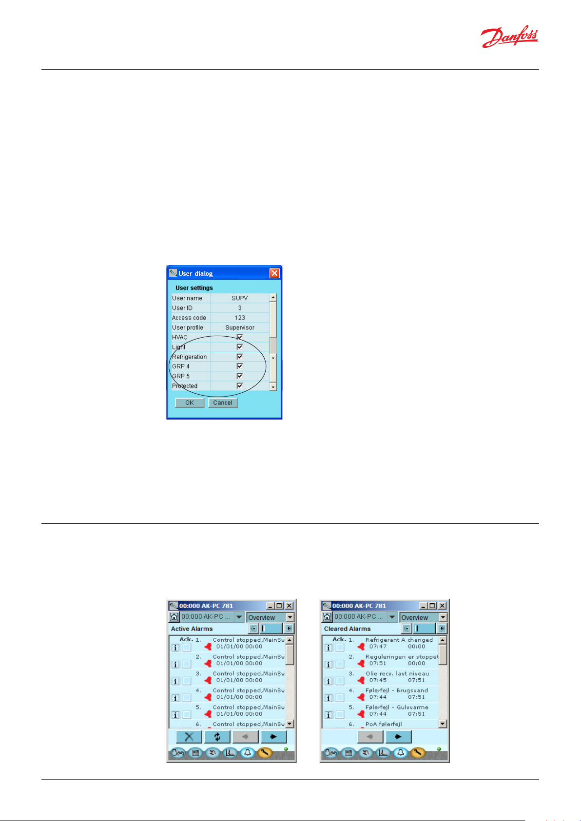
9. Authorisation of users
New users are established here and existing users can change their access code. To get access to the
menu you must be logged on as super user. Only with this user type can you authorise other users and
change their access codes.
You can establish four different profiles:
Default (DFLT). Lowest level which only displays elementary operating data.
Daily user (DAIL). Second lowest. Typically for the person responsible for refrigeration in a shop. He/
she can read alarms and set operating data and cancel alarms.
Service user (SERV). An installer/service engineer who partly installs and runs in the plant, partly
performs more radical settings/adjustments, overriding the automatic controls in connection with a
service call.
Super user (SUPV). A plant builder/person responsible for monitoring of it with top-level
responsibility. He/she has as the only one the right to authorise other users.
Start by becoming authorised for configuration. You do this by selecting “Supervisor” in the log-in
display followed by an access code. You can now set up/authorise new users.
Not used
10. Alarms
Procedure
1. Give the user a short “name” of max. four characters
2. Supplement with an ID number which is not known/used already
3. Write an access code (a number) which is not higher than 9999
4. Assign the required profile to the new user
5. If it is a large plant and the user needs access to, say, heating and ventilation, the final field must
also be checked.
6. Finish with OK.
The two alarm displays show the active alarms and earlier alarms, respectively. If you want to know
more about one of the alarms you can click on the alarm and in this way download an info display on
the screen.
If you wish to confirm that you have seen an alarm, you can check it in the square field. Remember
that the error may still be there and has to be corrected.
© Danfoss | DCS (vt) | 2021.04 BC173186427013en-000702 | 9
Page 10

User Guide | Service tool, AK-ST 500
The four keys have the following functions:
With the first key you sort out the alarms, so that only the active ones will remain.
The second key will update the display (checks whether more alarms have been added
Each page represents 20 alarms.
11. Log function Here you can collect measured values and have them presented as curves.
while the display was shown).
With the third and fourth keys you can turn over the pages with alarms.
Measurements are defined here.
Graphics are shown and defined here.
Definition of measurements. Here is Pgc selected.
Type = General registration or a collection for service use
Interval = How often to save a value
Period = Time when the measurement is saved. Then overwritten.
© Danfoss | DCS (vt) | 2021.0410 | BC173186427013en-000702
Page 11

User Guide | Service tool, AK-ST 500
Measurement
1. Select a parameter in the field left
2. Lead it into the right field by pressing the arrow button (or double click on the parameter)
3. Finish by pressing “OK”
Data collection starts when the set-up is locked and the controller is started, the clock is set and
start is activated.
The Graphic
12. Connection to an
external system
History = Log data, i.e. accumulated data.
Trend = Trend data, that is to say data that are collected and displayed here and now.
Export = Export the collected values to a file.
The file can be opened in Excel.
Print = Print out the accumulated values on a printer.
= Moves back and forth in time.
If you need to set up a connection to an external system, this must be done from the “Site selection”
screen you see when you start the programme.
Here the following are shown:
Direct: Used when the controller is connected directly to the PC.
Offline: Used when programming takes place without a controller (see page 13).
In addition, it is possible to define external connections, e.g. via modem and TCP/IP.
When the selected connection has been defined, it can be selected just like any other.
© Danfoss | DCS (vt) | 2021.04 BC173186427013en-000702 | 11
Page 12

User Guide | Service tool, AK-ST 500
Generally about Site Setup
• Site name/location/type are free text fields. Connections are sorted by ”Site name”
• Destination name: Must correspond 100% to the destination set up in the recipient’s System
Manager
• Pass code: Must correspond 100% to the password entered in the recipient’s System Manager.
• In case of connection to SM 800A System Manager the checkbox “Enhanced security” must be
checked.
Modem:
• Phone number: Number of recipient.
• Com PORT: Number where the local modem is connected
• Baud: Baudrate to local modem (default is 38400)
• AT1 command: Initiation string to local modem
• Modem type: Free text for modem type.
TCP/IP:
• IP address: IP address of recipient
• TCP port: Must be 1041
DNS name:
• Use if the recipient uses a DNS address.
13. Backup When setting a controller, all of its settings are saved in a backup file. This file can then be saved for
security purposes, or it can be used to copy and import settings in a similar controller.
Furthermore, you can use the file for ”Offline programming”, in which you prepare all settings in order
to copy the file onto a controller at a later time.
This function can be found below in the controller’s Configuration menu.
Press ”Copy settings” Press ”Copy file” Give the file a name xxx.bck
© Danfoss | DCS (vt) | 2021.0412 | BC173186427013en-000702
Page 13

User Guide | Service tool, AK-ST 500
14. Offline settings
Here you can work on a file which you can then later transfer to a controller.
It is required that you have a basic .bck file to work from. This must be a file with the same order
number and software version as the controller.
The file is a backup file from a system.
It is possible to change settings. Measured values will of course not be displayed. Likewise, functions
requiring online connections are omitted.
1. Select site , Offline, Press Connect
2. Select backup folder
3. Select file. The file is named in the following way: ”network address” # ”order number” # ”software
version” # ”controller name”.
If min/max values do not exist in the file, a dialogue will appear.
The decision to download min/max values must be set under the Service Tool setup (see above).’ ‘
The set values will be saved automatically along the way.
15. Languages
16. Customer defined texts
The individual controllers operated by the Service Tool contain one or more language selections.
English texts are available in all controllers.
On those controllers where it is possible to select a language, the desired language will be shown in
the display. However the controller will return to English in cases where the translation is incomplete.
A number of controllers only have English. In these cases the Service Tool downloads a translation
from a file supplied with the tool. The language selection is carried out in the display where the
Service Tool can be configurated. If the selected language is not found in the supplied file, the
controller will return to English.
Alarm texts
The language for alarm texts has to be set in the System Manager AK-SM 720 and the connected
controllers. In this function, the System Manager will show the desired language, if it exists in the
System Manager. If not, the alarm text will return to English.
If you wish to change some of the texts that are used in the Service Tool, you can do so in the
following way:
1. Select the start screen in configuration
© Danfoss | DCS (vt) | 2021.04 BC173186427013en-000702 | 13
Page 14

User Guide | Service tool, AK-ST 500
2. Press Edit
3. Type in the original text as you see it. Capital letters and spaces must be included.
4. Type in an equal sign “=”
5. Type in your new text.
6. Save the file.
7. Mark the field “Custom Language”
8. Restart the Service Tool
Example:
(This setting does not apply to alarm texts).
17. Plant overview
With this function you can create an overview over a range of data from the plant.
This will contain:
Address, Name of controller, Parameter, Value.
Up to 99 parameters can be gathered, but only those that can be logged.
Example:
This is how you define the overview:
1. Press “Home”
2. Press “Site functions” and then ”Site overview”
3. Press ”Select”.
Modem info
Change controller name on plant
You can only access this function in a System Manager.
© Danfoss | DCS (vt) | 2021.0414 | BC173186427013en-000702
Page 15

User Guide | Service tool, AK-ST 500
4. Select controller and parameter
5. Finish by pressing “OK”
18. Update software If the software in a controller requires an upgrade, use the following procedure:
1. Connect the Service Tool directly to the controller
2. Start the update function in the Service Tool - configuration
3. The update display is shown here
4. Find the file containing the new software
5. Tick the ”Restore settings” box (after the update, the previous settings will be reused).
6. Press ”Start”.
© Danfoss | DCS (vt) | 2021.04 BC173186427013en-000702 | 15
Page 16

© Danfoss | DCS (vt) | 2021.04 BC173186427013en-000702 | 16
ADAP-KOOL®
 Loading...