

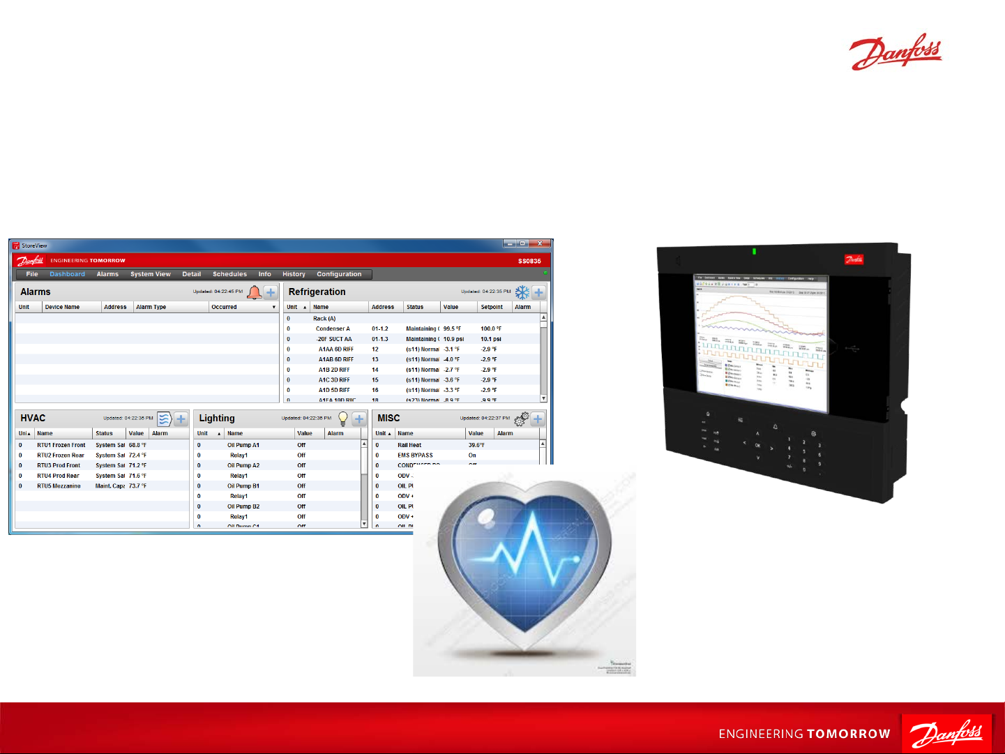
AK-SM 800 IO Offline Troubleshooting
AX279128111283en-000101
1 |
Department (slide master)
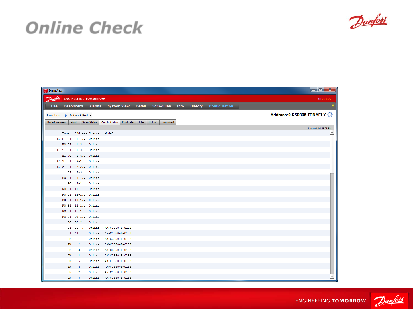
Online Check
1. From Network Nodes screen go to ‘Config Status’ tab
2. Each line item indicates a single module/controller
3. Verify all programmed modules are online
2 |
Department (slide master)
IO Communication Issues
Initial Checks
Power
Does module exist?
Comm module rotary switch
Proper comm module type?
AK-SM 800 Checks
Proper channel enabled?
Wiring Issues
Does polarity matter?
EOL resistors
Daisy-chaining and 800 termination
Type of wire used
Problem Correction
Rescan
3 |
Department (slide master)
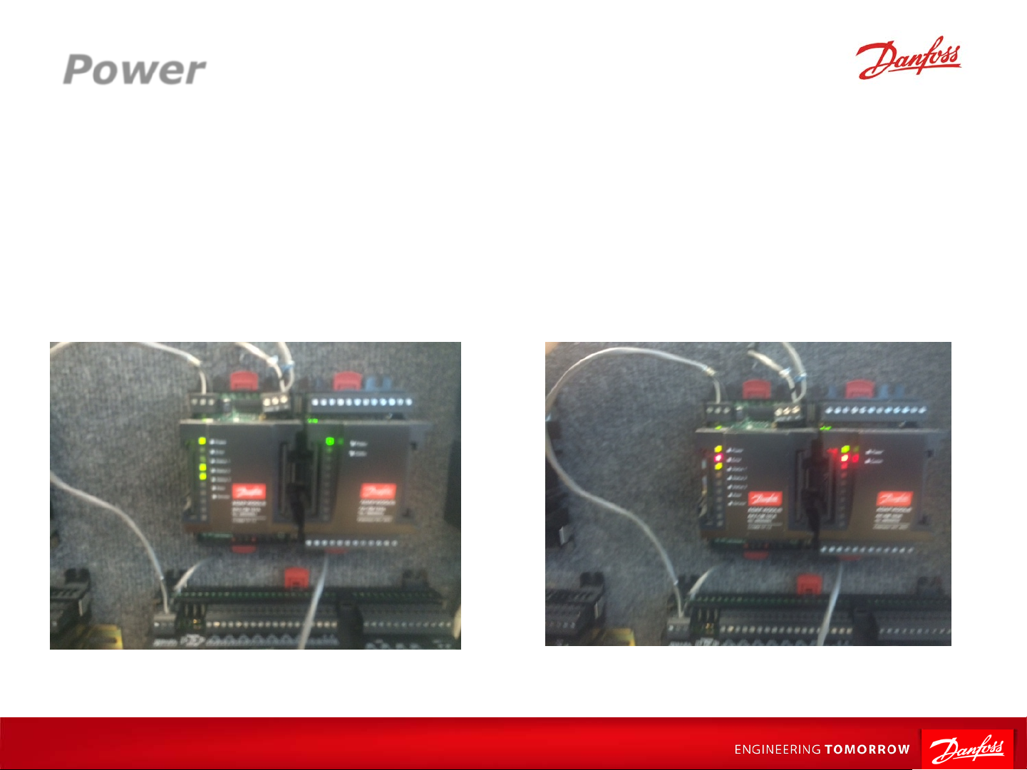
Power
1. 24Vac/dc required for comm module*
2. Solid green indicator at top if power ok
3. Individual Power LED on each module as well
nd
4. Comm module requires connection to 2
*Will power at lower voltages (i.e. 12V), but will not bring connected modules online
module to power
4 |
Department (slide master)

Addressing
AK2 Module Format Uses 3 Numbers
Alternative Formats
Calculated- ‘Ca-XX’ format
Case Controllers-1 N um b er
Legacy IO (AKCess)-2 Numbers
5 |
Department (slide master)

Does Module Exist?
Up to 9 modules of any combination connected to 1 C.M.
Comm.
Module
0 0 1
Analog Inputs
1 2 3 4 5 6 7 8
Module
1
1 2 3 4 5 6 7 8
Digital Outputs
Analog Inputs
1 2 3 4 5 6 7 8
Module
2
1 2 3 4 5 6 7 8
Digital Outputs
IO Module #2
Digital Output #7
Bd - Pt
Analog Inputs
1 2 3 4 5 6 7 8
Module
3
1 2 3 4 5 6 7 8
Digital Outputs
Set address using
rotary switches
6 |
Department (slide master)
Comm.
Module #1
01 - 2.7
Note: “0” Key
toggles decimal (“.”)

Comm Module Rotary Switch
3 Rotary Dials determine address
First dial should always be set to 0
Remaining dials determine add ress for 800
To adjust dials after system is po wer ed:
1. Adjust dials to desired #’s
2. Rescan system
*Addresses cannot be duplicate d
7 |
Department (slide master)

Comm Module Typ e
Controller Native Comm
Part #
Module Type
AK-SM 850 AK-CM 101C 080Z0063
AK-SM 880 AK-CM 101C 080Z0063
AK-SM 880R AK-CM 101A 080Z0061
8 |
Department (slide master)
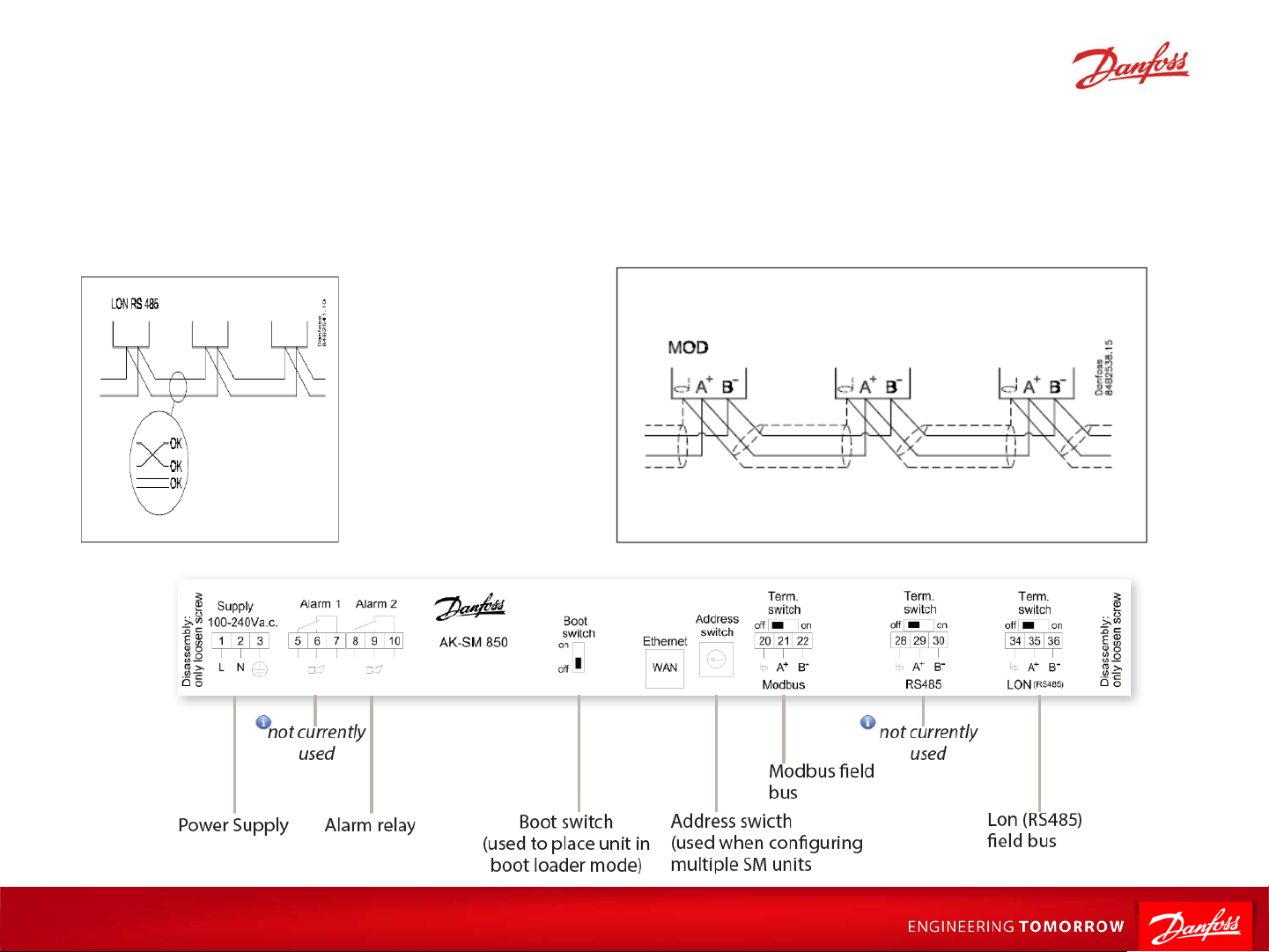
Wiring-Polarity
1. LON wiring is not polarity sensitive (TP78 or RS485)
2. Modbus wiring is polarity sensitive
3. Ensure wire not incorrectly landed on shield terminal
9 |
Department (slide master)

Term Switches and EOL Resistors
1. AK-SM at end of loop
Term Switch = On
10 |
Department (slide master)
1. AK-SM in middle of loop
Term Switch = Off
*Resistors now ship
loose in bag

Final Checks/P roble m Correction
Final Checks
If nothing found with other checks, replacing offline module(s) is final step
If full row of modules is offline, comm module should be changed as well
Replace modules one at a time in case one module is affecting others
Problem Correction
Once problem has been identified and corrected, complete rescan
11 |
Department (slide master)
 Loading...