

Page 1
Quick Setup Guide
AK-System Manager
AK-SM 800
ADAP-KOOL® Refrigeration Control System
Page 2

Quick Setup Guide | System Manager, AK-SM 800
Contents
Document History .......................................................................3
Mounting Specications .............................................................4
Installation ...................................................................................5
Connections .................................................................................7
Network topology .......................................................................7
Remote Management Tool (RMT) .............................................10
Initial Conguration - language ...............................................12
Initial Conguration - Wizard ...................................................13
Conguration .............................................................................16
Service Tool Support .................................................................34
General navigation, operation and use (via web) ...................35
Connecting to your AK-SM: .................................................................35
Dashboard view: ..................................................................................... 35
Managing alarms: ................................................................................... 36
Device detail: ............................................................................................ 37
System view: ............................................................................................. 38
Schedule view: .........................................................................................39
History (Logs) .............................................................................40
Collecting and viewing history .......................................................... 41
Updating Software (via USB Flash Drive) ................................42
2 | USCO.PI.R1.H2.02 |
© Danfoss | ADAP-KOOL® | 2015.10
Page 3

Quick Setup Guide | System Manager, AK-SM 800
Document History
Document Notes
USCO.PI.R1.H1.02
Document revision
First document release
© Danfoss | ADAP-KOOL® | 2015.10
USCO.PI.R1.H2.02 | 3
Page 4
Quick Setup Guide | System Manager, AK-SM 800
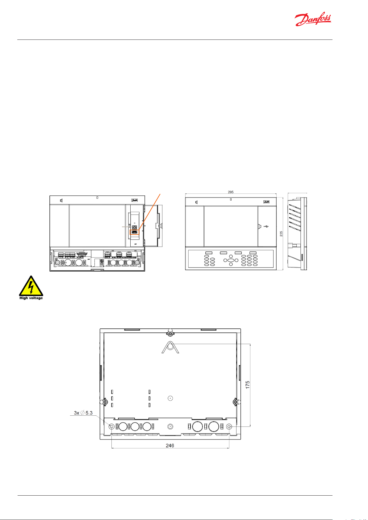
Mounting Specications
The mounting location should be at, dry and free of major vibrations. The AK-SM 800 should be mounted at eye level.
Dimenstions:
Unit Width 295 mm (11.6”)
Unit Height 235 mm (9.3”)
Unit Depth 65 mm (2.5”)
Mounting holes 246 mm (9.7”) Width
Mounting holes 175 mm (6.9”) Height
Operating temperature:
Screen: -10 to +55˚C (14 to 131˚F)
@ 90% RH (non condensing)
Electrical range: ~ 100 - 240 V a.c. (+ / - 10%) 50/60 Hz
Built in alarm relay 240 V a.c. Class II 3 Amp inductive, 5 Amp.
ohmic
Approvals: CE
IP 20
USB Access door
Active USB Flash drive (use for load/save database and AK-SM software)
65
Not currently Used
WARNING: To avoid risk of injury from electric shock, ensure correct electrical isolation is made
before working within the enclosure.
4 | USCO.PI.R1.H2.02 |
© Danfoss | ADAP-KOOL® | 2015.10
Page 5
Quick Setup Guide | System Manager, AK-SM 800
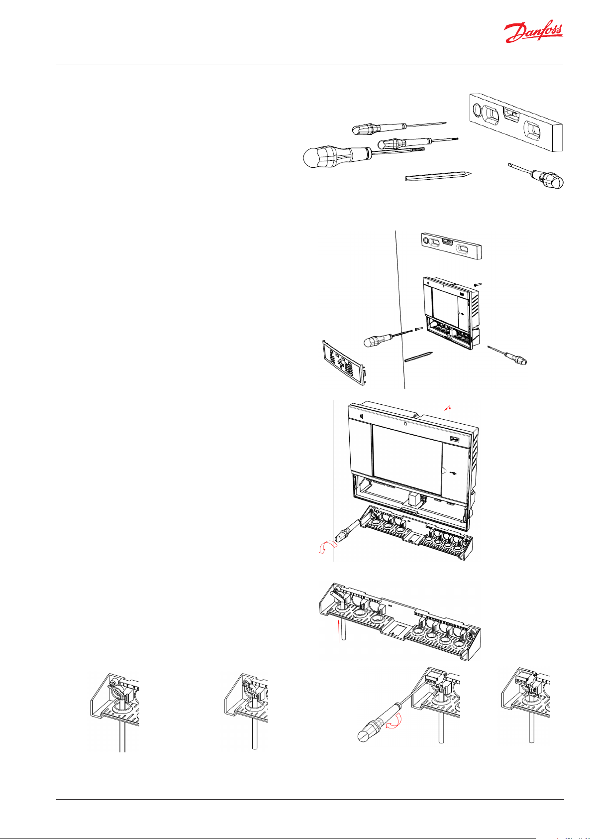
Installation
Tools needed
Bubble level
Small slotted screwdriver for connector screws
Torx 8 screwdriver for releasing the electronic unit and for
fastening the unit when recessed mounted
Screwdriver for xating the AK-SM 800
Pen for marking the 2 lower xation holes
Larger slotted screwdriver for releasing the Technician lid
Wall Mounting- box
Attach screw to the wall
Mount AK-SM 800 to the screw
Loosen Technician lid (three sides)
Remove Technician lid
Level the AK-SM 800
If drilling is necessary, mark up 2 screws in Connector part.
Attach the Connector part to the wall using another 2 screws
Wall Mounting- wiring
Insert cables through the rubber grommets
Strip the cables Strip the wires
© Danfoss | ADAP-KOOL® | 2015.10
Secure wires in connectors by screwdriver
Strain relief the cables
USCO.PI.R1.H2.02 | 5
Page 6
Quick Setup Guide | System Manager, AK-SM 800
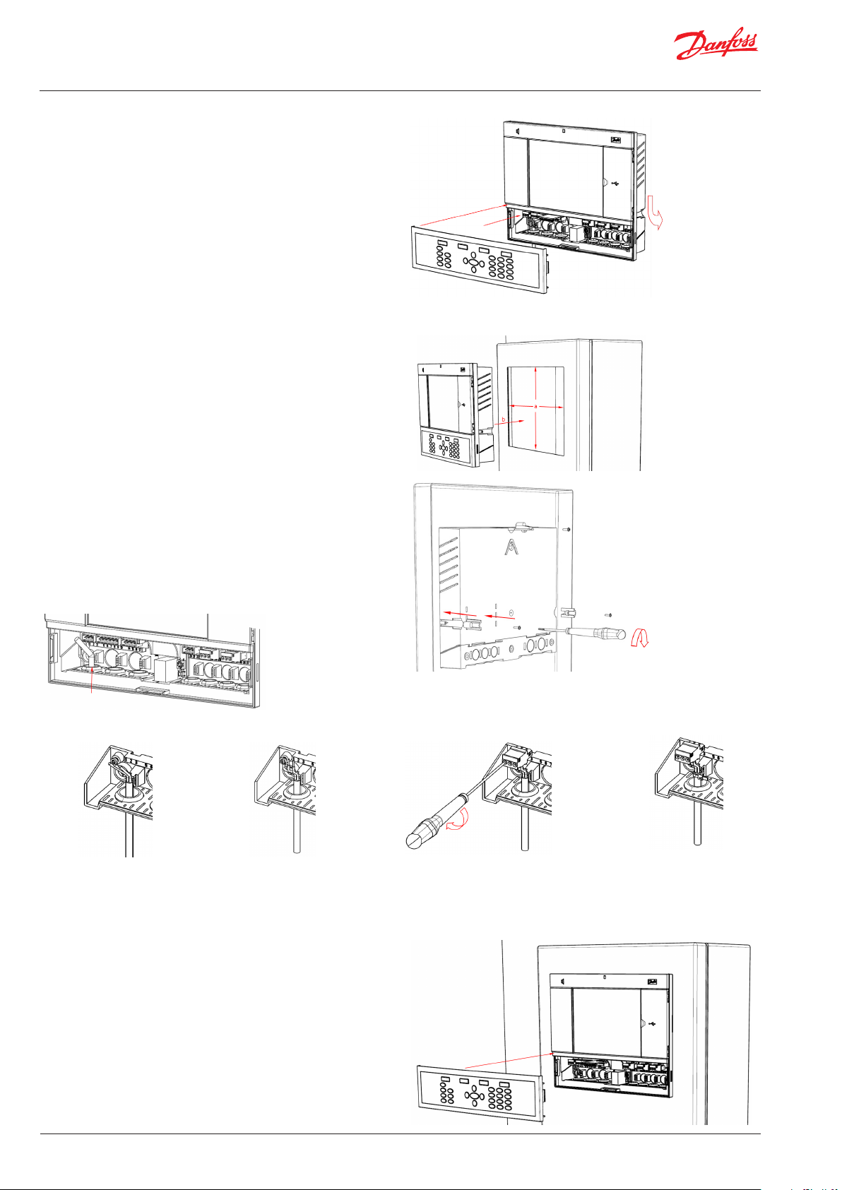
Carefully replace the keypad, ensure that it securely snaps into
place
Wall Mounting- Panel recessed
From the front:
A hole of the size 280 x 220 mm is machined
The AK-SM 800 is inserted in the hole
From the backside:
Slide the 3 fastener into the housing part
The screws are inserted into the fasteners
Secure the unit by tightening the screws
Remove Technician lid
From the back, push cables inside the housing
Strip the cables Strip the wires
Secure wires in connectors by screwdriver
Strain relief the cables
Carefully replace the keypad, ensure that it securely snaps into
place
6 | USCO.PI.R1.H2.02 |
© Danfoss | ADAP-KOOL® | 2015.10
Page 7
Quick Setup Guide | System Manager, AK-SM 800
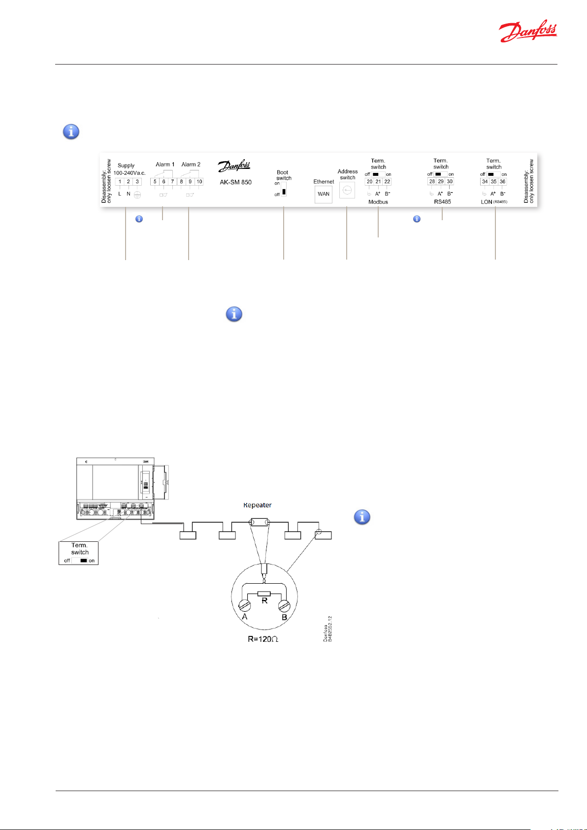
Connections
The following chapter describes the available connections on
your AK-SM 800.
Please note that not all connection points are currently
active, please refer to the drawing below for more details
not currently
used
Power Supply Alarm relay
Boot switch
(used to place unit in
boot loader mode)
RJ 45 LAN, Use shielded Ethernet cable
Network topology
Your AK-SM supports both Modbus and Lon RS485 local bus
connections. For further detailed description of network
connections please refer to document ‘Data Communication
between ADAP-KOOL® Refrigeration controllers_RC8AC602’
Lon RS485
Follow standard topology guidelines for Lon RS485, with
particular respect to maximum cable length, when to use a
repeater and ensuring suitable resistors are in place.
Modbus eld
bus
Address swicth
(used when conguring
multiple SM units
When using the Lon RS485 network, ensure the
Term. Switch on the AK-SM is in the ‘ON’ position
(enable internal resistor). Any repeaters must
also have 120Ohm resistor in place. Finally, ensure that the last controller on the network run
also has its end of line on line resistor enabled.
not currently
used
Lon (RS485)
eld bus
Cable type
Cables twisted in pairs must be used, and they may be provided
with a screen. Some types of communication require a cable with
a screen to be used. The conductor’s cross section must be at
least 0.60 mm. Examples of cable types:
Belden 7701NH, single-thread 1 x 2 x 0.65 mm, without screen
Belden 7702NH, single-thread 2 x 2 x 0.65 mm, without screen
Belden 7703NH, single-thread 1 x 2 x 0.65 mm, with screen
Belden 7704NH, single-thread 2 x 2 x 0.65 mm, with screen
LAPP UNITRONIC Li2YCY (TP), multi-thread 2 x 2 x 0.65 mm, with
screen
Dätwyler Uninet 3002 4P, single-thread 4 x 2 x 0.6 mm, with
screen
© Danfoss | ADAP-KOOL® | 2015.10
USCO.PI.R1.H2.02 | 7
Page 8
Quick Setup Guide | System Manager, AK-SM 800
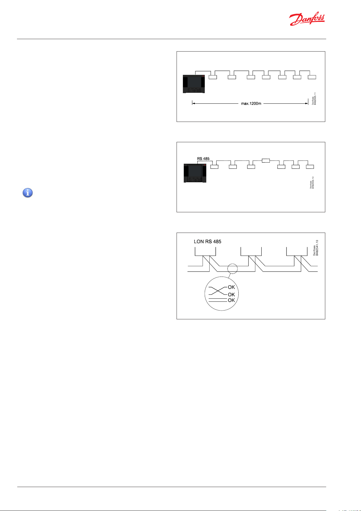
Cable length
A cable length must not exceed 1200m (4000 foot). A repeater
(Part # 084B2241 ) must be used for longer lengths.
Lon RS485 Topology
The cable connection must be connected from controller to
controller, and no branches are allowed on the cable. If the cable
length exceeds 1200 m a repeater must be inserted. If the data
communication cable runs through an electrically noisy environment which impairs the data signal, one or more repeaters must
be added to stabilise the signal.
When conguring Lon devices on the control bus, the
highest device address that can be can be used is 127 (max. 120
controller in total)
AK-SM
AK-SM
Conductors
The two wires are looped from device to device. There are no
polarisation requirements. (On some controllers, the clamps are
designated A and B. On others there is no designation. Otherwise
the connections are identical.) If a screen is used, it must be
connected to the system device and any repeaters. A screen must
always be looped from device to device.
The screen must not be connected to anything else.
(The screen is earthed inside the screen and must not be earthed
in any other way.)
8 | USCO.PI.R1.H2.02 |
© Danfoss | ADAP-KOOL® | 2015.10
Page 9
Quick Setup Guide | System Manager, AK-SM 800
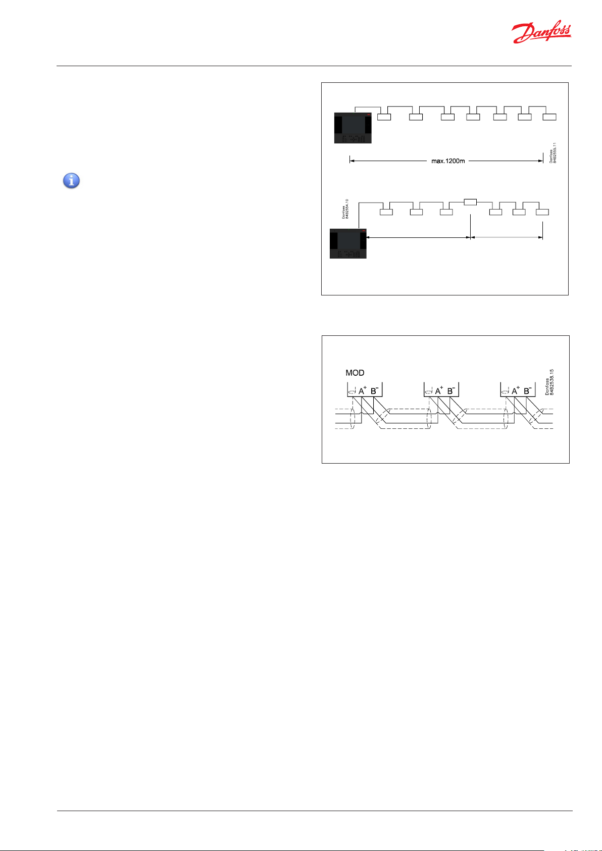
Modbus topology
The cable must be with screen. The cable is connected from controller to controller, and no branches are allowed on the cable.
If the cable length exceeds 1200 m a repeater must be inserted
One repeater must be added for every 32 controllers. If the data
communication cable runs through an electrically noisy environment which impairs the data signal, one or more repeaters must
be added to stabilise the signal.
When conguring Modbus devices on the control bus,
the highest device address that can be used is 127 (max. 120
controller in total)
AK-SM
The wires are looped from device to device.
A is connected to A
B is connected to B.
The screen must be connected to the system device, all controller
and any repeaters.
A screen must always be looped from device to device.
The screen must not be connected to anything else.
AK-SM
32
32
© Danfoss | ADAP-KOOL® | 2015.10
USCO.PI.R1.H2.02 | 9
Page 10
Quick Setup Guide | System Manager, AK-SM 800
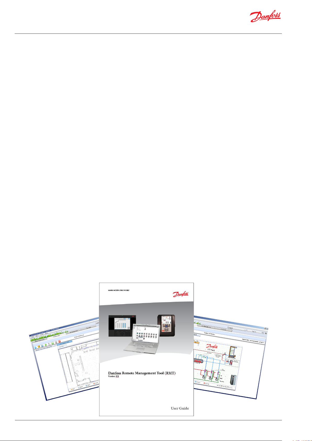
Remote Management Tool (RMT)
The Remote Management Tool (RMT) is a PC software application
tool that is designed to support the AK-SM, both in commissioning and service. The RMT is a powerful tool that allows full oine
programming and simulation of AK-SM databases, providing the
opportunity to save considerable on site commissioning times.
In addition, the RMT tool has various remote management
features, facilitating complete system management. Creating
custom images for the AK-SM web browser is also another
function of the RMT tool. The following features can be seen in
th e RMT;
• Oine web Programming
Launch oine web simulator(s) to allow full oine AK-SM
database programming, with controller simulation you can
fully pre-program your application and save the resulting
database to USB for on site install.
• Program simulation
From within the web browser session simulate board and
point variables to test calculations and system behaviour
• Custom Graphics
Use your own Jpeg or bitmap le to crate custom images,
mapped with any congured system data point
• F TP (File Transfer Protocol)
Remotely connect, load and access system les (html web &
EDF device les) Retrieve data points
• Address Book
Save your most commonly connected site details to allow
for one click connection
• Tools
Download System software, backup (save) & load database
les.
• Language
Compatible in multi- languages
The RMT tool is available from your Danfoss sales oce with
associated supporting documentation.
10 | USCO.PI.R1.H2.02 |
© Danfoss | ADAP-KOOL® | 2015.10
Page 11
Quick Setup Guide | System Manager, AK-SM 800
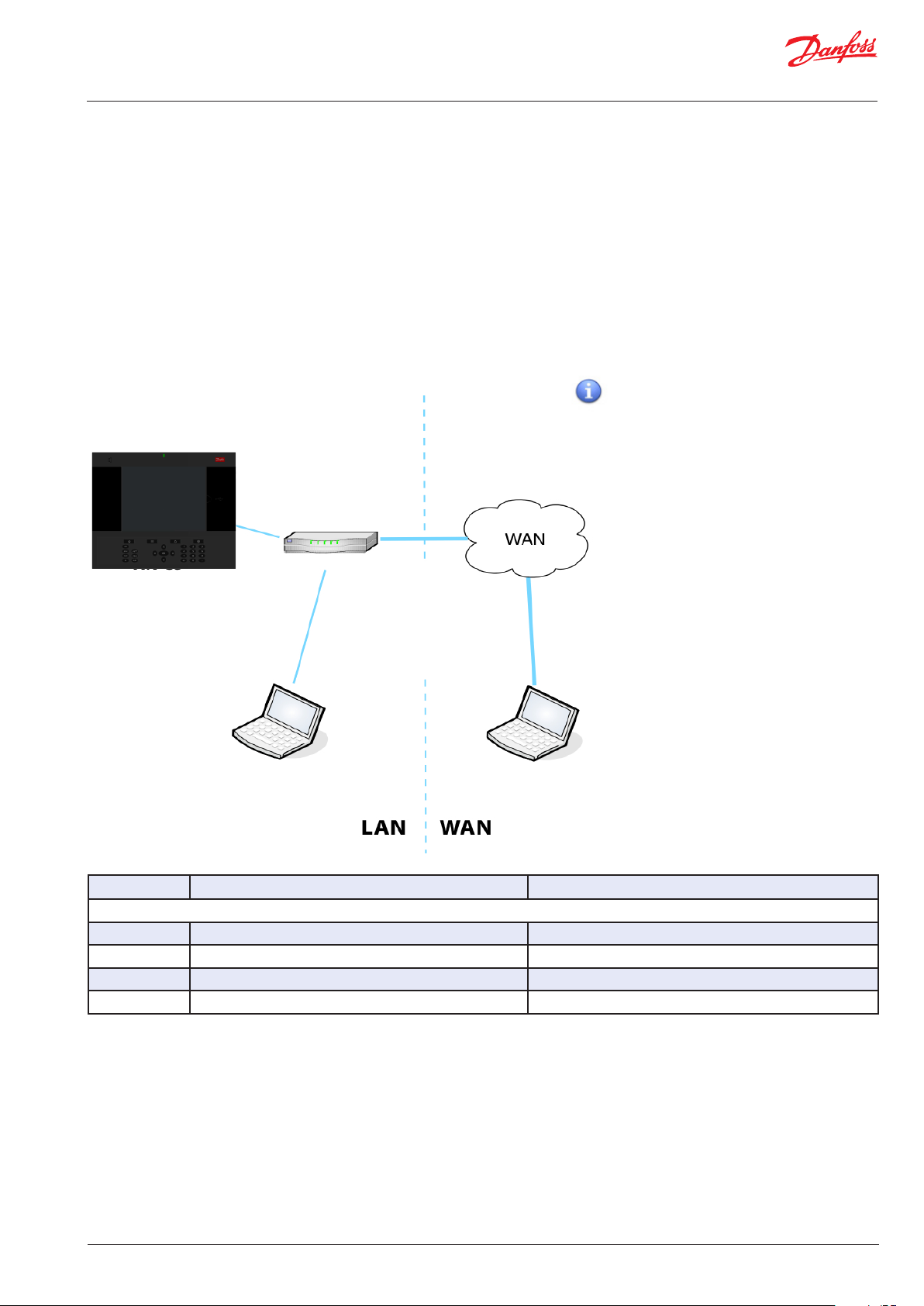
Required IP ports
As the AK-SM uses IP networking standards to create remote
access it may be necessary to congure any site routers to allow
incoming connections, either from a LAN or WAN view. The gure
below shows a simple IP connection with the AK-SM connected to
a standard network router with a typical factory IP address range.
From within the LAN any remote connections should ‘point’ to
the master IP address of the AK-SM, in this example
http://192.168.1.100. If however the remote connection is on a
WAN then the LAN router may need to be congured to allow this
inbound connection, with the addition of the web port added tot
he end of the http sting.
Please refer to the port allocation table below for remote IP
connections
Ma ste r IP 192 .168.1.10 0
De fault Gatew ay 192.16 8.1.1
Network Mask 255.255.255.0
(AK-SM factory set http port = 80)
LAN Network Router
IP 192 .168.1.1
LAN Network Router
AK-SM
WAN IP 172.28.6.108
For WAN access port
forwarding is required
1. The port number is required to be typed
into the URL address ONLY if the web port is
NOT congured as 80. For example, if the port
number is congured as 8080, then Computer
A needs to type in ht tp: //192.168.1.100:8 080,
while Computer B needs to type in
http://172.68.6.108:8080 to access the website
of the unit.
2. If the port number is dened as default
number 80, then it is not necessary to type in
“:80” in the URL address, this is because the
HTTP protocol uses 80 as default port. If the
router port forwarding is correctly congured,
it is not required in WAN access either.
Computer A
type ‘http://192.168.1.100’ to access AK-SM
Computer B
type ‘http://172.28.6.108 to access AK-SM
Port allocation table
IP Port Use Notes
- LAN side -
80 web browser This port is user congurable but factory set to 80
21 RMT tool This port is user congurable but factory set to 21
25 e-mail e-mail output
3001 XML Used for XML communications
Notes for FTP port forwarding in AK-SM units
In AK-SM units, FTP service is a convenient way to download/
upload les and updating database/code. Open FTP server
ports to the public internet is not considered as a safe network
practice. To avoid these issues, Danfoss strongly suggests FTP
functionality in LAN network only . This would reduce the risk
of open FTP ports and enhance network security. However, to
make the FTP work on WAN side, it must have configured FTP
server port opened and forwarded to the public internet.
© Danfoss | ADAP-KOOL® | 2015.10
USCO.PI.R1.H2.02 | 11
Page 12
Quick Setup Guide | System Manager, AK-SM 800
Initial Conguration - language
The following section describes the recommended actions
to get your AK-SM up and running.
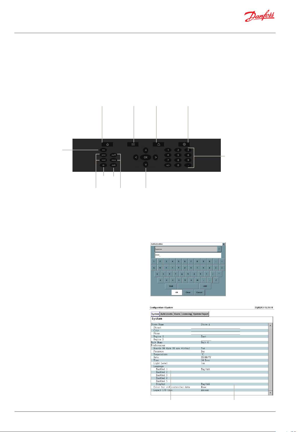
Local keypad - button layout
Home
(System View)
Menu
Escape
Back Shift
Previous
Next
Setting language for local SM display
Your AK-SM can display several different languages. The
factory default the unit will display English, in addition your
required language can also be enabled. Follow the simple
steps below to display your preferred language in the local
screen;
1/ Press the Configuration button, and if required enter the
factory default user name and password (Supervisor, 12345)
Page Up
Page Down
Alarms Configuration
Numeric keypad
Menu Navigation
2/ Using the arrow keys, navigate to the ‘System’ memu.
3/ Using the down arrow, navigate to the Language line and
select your required language
4/ Select your language for ‘Display’. The unit will then request
a re-set.
12 | USCO.PI.R1.H2.02 |
Select language
Display language
© Danfoss | ADAP-KOOL® | 2015.10
Page 13
Quick Setup Guide | System Manager, AK-SM 800
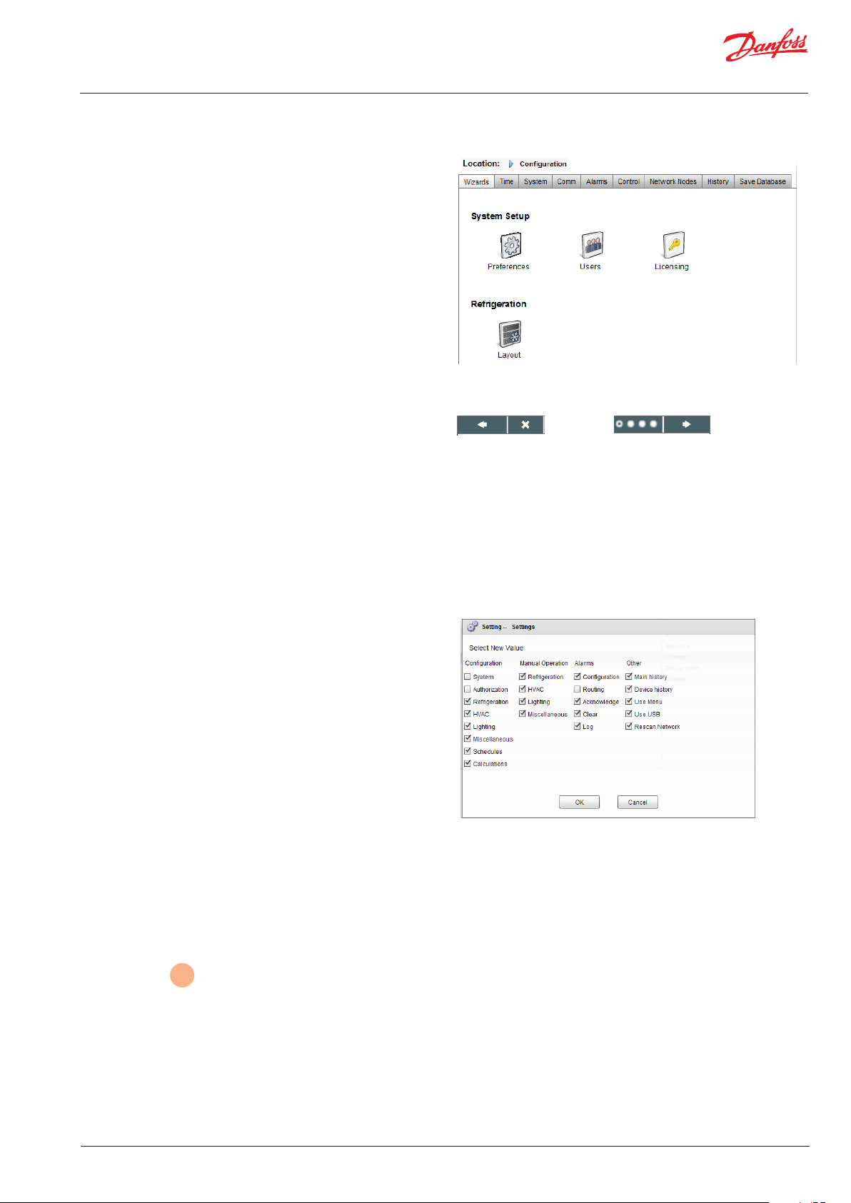
Initial Conguration - Wizard
The following section describes the current Web Wizards, used
for simplifying initial settings and Refrigeration layout. The Web
Wizards can be used in an oine or online conguration.
Danfoss recommends using the AK-SM web environment for
commission tasks.
Establish a web connection to your AK-SM (if working online,
enter the valid IP address of the AK-SM and apply the factory user
name and password). Navigate to the Configuration menu
Preferences Wizard (Language, store names, units, preferences,
time, date, daylight savings)
1/ To easily congure your units preferences, launch the Prefer-
ences wizard. Use the Wizard navigation controls to move
thought the Wizard screens.
2/ To make changes, double click on the relevant line and
continue until the nal screen.
3/ Press the nish button to complete and close the wizard
(return to main wizard screen)
Web Wizard Navigation
Back Close Progress Forward
Users Wizard (Create, modify users, user groups, authorization
levels)
1/ Enter number of users required (max 22), set password and
browser language for each user
2/ Enter the number of authorization types (max 7), against the
settings line double click to modify the scope of system access
3/ Press the Finish button to complete the Web Wizard
Licensing Wizard (Enter new license functionality)
Not currently used
Refrigeration layout Wizard (used to dene your refrigeration
layout, grouping case with packs, forming associations)
One of the main features of the refrigeration layout wizard allows
the user to make use of a network scan. The principle is that the
wizard is initially used to initiate a network scan, discover and list
what is found. This discovery is then used to easily dene the
Pack and Case controller relationships (suction groups). The
wizard allows for easy drag and drop association, the net result is
that once completed the refrigeration layout is built in the AK-SM.
The Refrigeration layout Wizard can be used during a live connection to your AK-SM or can be used when programming oine.
limitations: Whilst the wizard will layout the Pack and Case
relationships, further controller conguration may be required.
Refer to section
any remaining conguration areas required. Currently the wizard
is intended for Pack and Case devices, any controls not designated as such will have to be congured using traditional cong
methods (see Conguration section).
6
under ‘ Conguration’ for guidance on
© Danfoss | ADAP-KOOL® | 2015.10
USCO.PI.R1.H2.02 | 13
Page 14
Quick Setup Guide | System Manager, AK-SM 800
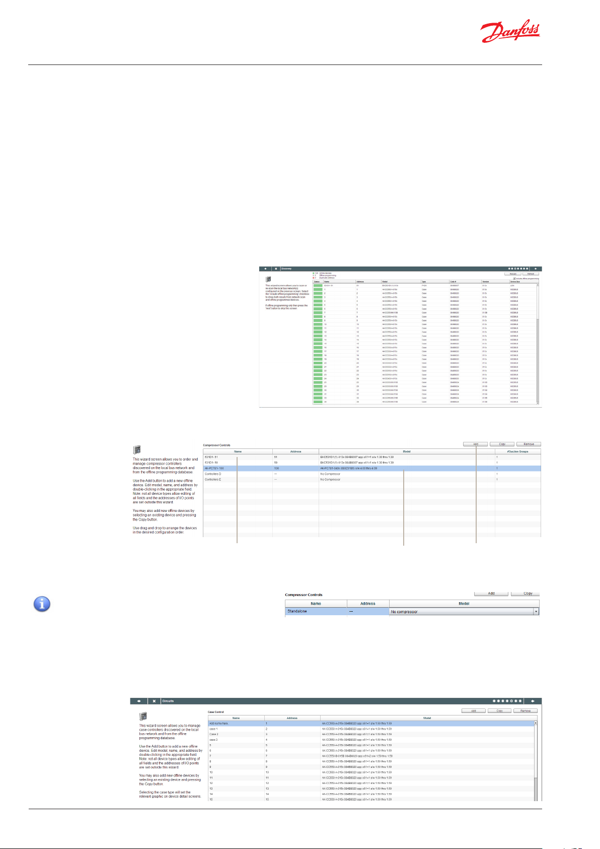
Open the Refrigeration layout wizard and follow the described
steps, each step has some description for the available actions.
The following wizard screens are available in sequential order;
Network (select and perform network scan)
Discovery (list scanned devices)
Compressors (Input Pack controller name, view address, model,
add, copy, remove)
Circuits (Input Evaporator controller name, view address, model,
add, copy, remove)
Suction Group mapping (Drag and drop your evap controllers
under each pack)
Summary (view your groupings before nishing wizard and thus
processing your selections to the AK-SM)
After the relevant networks have been selected an scanned the
‘Discovery’ screen will show all detected devices. Once satised
with the correct content press the forward button to continue
the wizard.
The ‘Compressors’ screen allows for custom text input. If working
oine (programming a database not being connected to a
AK-SM) the Add, Copy and Remove buttons can be used.
Double click the ‘Name’ line to enter a custom description for the
device. Pressing return will automatically focus on the next
device name in the list.
If your scanned list has known devices that are standalone (not associated with a Pack) these must be
mapped under ‘No Compressor’. Manually add a new
compressor and double click the model line and select
‘No Compressor’. When the nal wizard screen is
presented any standalone controls can be mapped under
this ‘No Compressor’ group.
The ‘Circuits’ screen follows the same principle as the Compressors screen.
Use the Add button when creating oine nodes. Double
click the ‘model’ line to bring up a selection of nodes
14 | USCO.PI.R1.H2.02 |
© Danfoss | ADAP-KOOL® | 2015.10
Page 15

Quick Setup Guide | System Manager, AK-SM 800
The ‘Suction group mapping’ screen allows for the dened
evaporator devices to be ‘mapped’ under the required Pack
controller. This mapping forms a relationship or grouping
between the pack and the evaporator devices. This grouping
association will then be seen in the AK-SM conguration and
dashboard screens (and can be used to easily set up master
control functions like Suction optimization).
As the user description indicates, use a drag and drop action to
group your controls. Use the CTRL key and multi-select cases to
save time when making bulk actions. You can remove any case
devices by simply dragging back to the available case list.
The check box labelled ‘Allow multi-case circuit creation’ is to
support Centralized refrigeration control conguration, where
multiple case circuits are available’. Leave this check box empty if
you are using a de-centralized control strategy (i.e. Case and pack
controllers)
Once satised with the mapping, press the forward button and
the summary screen will be shown. Pressing the nish button
will then send your conguration layout to the AK-SM. During
this time a progress bar will be shown and nally a status
dialogue box.
This completed wizard process will layout your refrigeration
application. Typically some additional conguration tasks will
then need to be completed (i.e. dene alarms, setpoint changes,
congure history), please refer to the following section for further
details on detailed conguration.
© Danfoss | ADAP-KOOL® | 2015.10
USCO.PI.R1.H2.02 | 15
Page 16

Quick Setup Guide | System Manager, AK-SM 800
Conguration
The following section describes the typical steps required for
commissioning and conguration of your AK-SM. Although site
applications can dier from one site to another, many setup
procedures are common. This setup section assumes the AK-SM
is mounted and all necessary power, network cabling and
controllers are in place. The described work ow is based around
the AK-SM web browser interface, but would equally apply if
being done via the local screen. Further detailed commissioning
instructions are found though out this user guide.
De-Centralized
Pack & Case
The AK-SM oers unique control exibility in that both centralized
and de-centralized control methods are supported. The term
‘centralized’ is used to describe the control of refrigeration Racks
via I/O (Danfoss Input / Output modules). Under this method of
control the refrigeration control is managed directly from the
front end (AK-SM), with eld bus I/O. De-centralized control is the
term used to describe the full support of Danfoss Pack and Case
controllers. Under this method, each Pack or Case controller on
the network can be seen as self contained, with control logic built
in. The front end (AK-SM) under this type of application is more of
a network manager, providing full read / write access and energy
saving functions.
When conguring your application, have in mind
which control strategy you wish to utilise.
Centralized
Rack I/O
When starting your system conguration you will have the opportunity to select either Centralized or De-centralized (or a mix of
both) control methods.
The following areas of system conguration will be covered in this
section;
Network Nodes (Network scan/ Node overview, Points, scan /cong status, duplicates, upload/download)
1
Time (Set time/date, time zone, operating Hours, Daylight savings, Holidays)
2
System (Store / Region Names, Units preferences, Authorization levels and users)
3
Communication (DNS, DHCP, IP Ports)
4
5
Alarms (XML, e-mail, Routing)
6
Control (Congure Refrigeration, Lighting, Miscellaneous, Energy meters and Gas detection)
Once successfully logged into the AK-SM (web) and assuming you
have the required authorization, system conguration is done via
the central ‘Configuration tab’. Clicking this tab reveals the
conguration ‘sub tabs’. Depending on your selection, these sub
tabs will change dependent on content.
Using the menu structure seen in the ‘Conguration’ page, a step
by step process can be applied when setting up your AK-SM.
Navigation ‘bread-crumb’
16 | USCO.PI.R1.H2.02 |
Central conguration menu
© Danfoss | ADAP-KOOL® | 2015.10
Page 17

Quick Setup Guide | System Manager, AK-SM 800
Network Nodes
1
If your application already has controllers and/or I/O modules
set and powered you may wish to perform a network scan to
validate their connection to the AK-SM. Follow this section to
perform a network scan
From the Conguration tab select the ‘Network Nodes’ sub-tab.
When your eld network is complete and all controllers are on
line a network scan can be initiated. The operation of a network
scan allows the AK-SM to be aware of any controller devices on
the network, allowing the AK-SM to communicate and function
with the controllers on the eld bus.
Use this screens to
perform network
scan
Relays | Sensors | On/Off | Variable Output
This tab relates to any AK I/O congured
points, the term points relates to AK I/O
relay, sensors, On/O Inputs and variable
outputs. Any control questions that have
required AK I/O control will be seen in
these tabs. The purpose of these tabs is to
allow the viewing of the I/O point status.
All nodes | Controllers | I/O boards | Other nodes
The scan status menu/tabs allows the user to view any scanned
nodes found on the network.
All Nodes: Central list will display congured devices and points.
Only congured controllers will be visible in this list.
Controllers: view any scanned generic controllers. This screen
will also reect address and controller type
I/O Boards: Display AK Board & Point status.
Other Nodes: List of other nodes
Ensure the appropriate network channel is selected, and press
the ‘complete rescan’ line. The AK-SM will now scan the network
to identify any connected and addressed controller nodes. The
text on the screen will reect the scan progress, after a scan the
time & date will be shown (indicating last scan)
For SLV support, select Modbus channel
‘Use this screens to
view status of your
assets (Online)
Duplicates Tab
Check this list to make sure no two devices have been assigned
the same network address. Any duplicate address will be
shown in this list. Correct any address issues and re-scan.
Upload Tab
The upload tab will list any controllers that have been uploaded.
The upload function can be performed in the Conguration>Control area (one controller at a time) or here (multiple devices
with one command). The process of an upload takes the
current parameter settings and values from the controller(s) and
loads them into the AK-SM database. This operation ensures
that the AK-SM database is synchronised with any pre-congured controllers on the control network. Any upload failure will
be shown on this screen, else a time / date stamp will be shown
when successful
Download Tab
The download tab will list any controllers that have been
processed for download (where the AK-SM sends parameter
data to the device). The download function can be performed
individually under the Conguration->Control page or here,
where multiple controllers can be selected for download (using
one command). The process of a download takes the AK-SM
database values and downloads them to the selected
controller(s). Any upload failure will be shown on this screen,
else a time / date stamp will be shown
© Danfoss | ADAP-KOOL® | 2015.10
USCO.PI.R1.H2.02 | 17
Page 18

Quick Setup Guide | System Manager, AK-SM 800
After the network scan has completed, any resulting count will be
seen against the Nodes Scanned on Network line - this reects
the number of found nodes on the scan just completed. The
corresponding line below (Nodes congured in database)
reects the current total of network nodes actually congured in
the AK-SM database.
The last group in this table refers to the following node types;
OI (Output|Input)
RO (Relay output)
SI (Sensor Input)
V02 (Variable output)
Utility Meter (WattNode, Veris, Carlo Garvazzi)
Generic (Danfoss case / pack controllers)
AK-CM (AK- Communication Modules)
Calculations
Each node (type) has a column that reects any congured or
scanned status.
2
System conguration (Time settings / preferences)
The Time tab allows the system time, time zone, operating hours,
daylight savings and holidays to be congured. Double click a
line to make any changes.
The following examples can be seen for the time zone;
London (GMT) = 000
Central Europe = 100
East Coast USA = -500
The operating hours can be set that reect your store operating
hours. Any times set in this section can then be referenced to
via a ‘Relative schedule’ . Relative schedules are found under the
‘Lighting’ and ‘HVAC’ application areas and apply a (user selectable) oset which references the operating hours schedule.
3
System conguration (Time settings / preferences)
18 | USCO.PI.R1.H2.02 |
© Danfoss | ADAP-KOOL® | 2015.10
Page 19

Quick Setup Guide | System Manager, AK-SM 800
After completing the required settings in the ‘time’ tab, navigate
to the ‘system’ tab. Under the system tab add the store name and
region / preference setting and information.
Use this screen to congure
‘Store name/details, unit
name, preferences, system
language’. Double click the
appropriate line to make
changes
‘Color for old controller data’ is
an option to reect data that
has yet been updated via a
network poll. Data with a *
indicates either an oine
condition or that the AK-SM is
waiting for a fresh update
from the device
Legacy I/O type is used to set
legacy supported devices
The Auth (Authorization) Levels tab allows the denition of up to
7 authorization types. Custom authorization types can be
congured with certain system privileges / access. In the
example below, 4 auth levels have been dened (factory setting
is 3). Level 1 (Supervisor) cannot have the settings changed. To
change the level of access of other auth levels, navigate to the
desired line and select from the Authorization pop up dialog box.
As factory standard, 3 levels are predened (Supervisor, Service,
Daily User), the service and daily user levels can be changed as
required.
The Auth (Authorization) screen allows
the denition of up to 7 authorization
types.
Reects what license is
congured for your AK-SM.
Dierent license allow
additional functionality
The Users screen allows the
denition of up to 20 users
The system report screen allows the user to dene
what content should be included.
Alarms, Schedules, scanned devices, Audit trail and
controller database are available options.
To generate a system report go the main web menu
and select File/Download Report
© Danfoss | ADAP-KOOL® | 2015.10
To add/delete auth levels select the ‘Number of
authorization types’ line (max 7 levels)
The Supervisor name can be changed but the level
of access / privileges are factory set.
Adding new auth levels allows new users to have
specic access to key system areas. Once new auth
types have been created, enter custom name and dene
level of access by selecting the Settings line (Authorization pop up box will appear)
USCO.PI.R1.H2.02 | 19
Page 20

Quick Setup Guide | System Manager, AK-SM 800
The following areas of authorization are available;
Conguration
System: Access to the System tab
Authorization: Access to the Authorization tab
Refrigeration: Access to Refrigeration conguration
HVAC: Access to HVAC conguration
Lighting: Access to Lighting conguration
Miscellaneous: Access to Misc conguration
Schedules: Access to Schedule conguration
Calculations: Access to Calculations conguration
Manual Operation (seen under Service tab in device detail
page)
Refrigeration: Allow user to perform the following operations
on Danfoss case controllers ;
Main Switch, Defrost, Cleaning, Lights, Night Setback, Shutdown
HVAC: Allow user to perform the following operations to Relay,
Inputs & sensor overrides
Lighting: Allow user to perform the following operations
-override relay
Miscellaneous: Allow user to perform the following operations
-override relay, sensor inputs
Alarms
Conguration: Allow user to congure alarms
Routing: Access to the alarm routing
Acknowledge: Allow user to acknowledge
Clear: Allow user to clear alarms
Log: Allow user to set alarm level to log
Other
Main Menu: Allow user to access main menu
Device History: Allow user to access device history
Use Menu: Allow access to Menu function
Use USB: Allow use of USB ash
Rescan Network: Allow user to rescan network
Users tab
The next tab (user tab) allows the denition of up to 20 users. A
custom name and password can be given for each user. The
appropriate level (dened in Auth Level tab) can be assigned to
each user. The AK-SM always maintains a single user in the
system prole and this level is factory set to the Supervisor level.
To add users simply enter the required value in the ‘number of
users’ line. The Browser language line reects what language will
be displayed in the web browser upon this user logging on [via
browser access].
To add users select the ‘Number of users’ and enter
required number
20 | USCO.PI.R1.H2.02 |
Enter custom name, password and auth level for
user.
Browser Language: This denes the language that
will be displayed when the user log on via the web
browser access.
© Danfoss | ADAP-KOOL® | 2015.10
Page 21

Quick Setup Guide | System Manager, AK-SM 800
Communication
4
The Comm (Communications) screen allows for IP network
settings to be congured. Follow the question lines on the screen
to congure your AK-SM according to site requirements. Any
changes in IP conguration will require an AK-SM system reset.
Select ‘Yes’ if a DNS service is to be used. Prefered host
name can be entered if setup in router cong
Select ‘Yes’ if AK-SM is to be connected to a DHCP server
Select yes and manually enter the IP address that the
AK-SM will use if DHCP fails.
Master IP address - if using multiple AK-SM controllers in
a host network, enter the Master (unit address 0) IP
address
Internet IP address - Specify public IP address which is
used to contact your AK-SM via an Internet based
connection. Factory web (HTTP) port is 80 & FTP port is
20 and 21, both can be changed to suit your network
application.
If your network supports NTP, select ‘yes’ to the
question ‘Network timing support?’
Alarms
5
The Alarms screen has a sub set of screen [Connections, Service, Alarm Routing, Relays, System, I/O Comm]. Go through each sub tab to
ensure all areas are correctly congured as per site requirements.
Dene the number of
connections (typically
network should be selected),
then select the connection
type [e-mail, Remote (Danfoss
Retail Care), XML)
The service tab is designed to
allow test alarms to be
generated. There is also an
auto alarm test that can either
be on a scheduled or repeated
basis.
The AK-SM utilizes an
Alarm Action Matrix that
allows a high degree of
exibility for various
alarm routing options.
At the heart of the alarm
conguration is the
‘Alarm Routing’ page,
where dierent routing
options can be dened,
along with time delays
and alarm output stop
conditions.
AK-SM system
based alarm
conditions
should be set
under the
System tab.
If the alarm output
includes relay(s) the
Relays tab should be
accessed to congure
the board & point
address for these relays
If Controllers (Danfoss Evap &
Pack, Power meters) and I/O
has been used in the control
conguration (Lighting, HVAC,
Refrigeration etc.), these
devices can be seen under the
I/O Comm tab.
© Danfoss | ADAP-KOOL® | 2015.10
USCO.PI.R1.H2.02 | 21
Page 22

Quick Setup Guide | System Manager, AK-SM 800
Connections screen - Dene the number of connections, then
select the connection type. Your AK-SM can oer the following
alarm IP based alarm output;
e-mail, Remote (Danfoss Electronic delivered services) and XML.
Depending on your conguration the screen will reect the
required inputs in order to satisfy the output. In order for any
alarms to be routed out of your AK-SM please ensure a schedule is
congured. Failure to set a schedule will inhibit any alarm output.
To congure a netwrok connection select
‘Number of network connections’
Type (e-mail | Remote | XML)
Ensure a schedule is dened to allow alarm
ouput
Example of e-mail conguration
Enter valid server name (or IP) for e-mail server
If your e-mail service requires user authorization, enter user name and password
Send to: Add the e-mail address for intended
recipients
Reply to: A mandatory eld that must
have a valid entry (address with same domain
name). An abbreviated message would have
reduced text in the alarm message
Congure a schedule to enable the alarm
e-mail output
22 | USCO.PI.R1.H2.02 |
3G Wireless routers
3G technology oers many benets over standard dial up
connections. Utilizing a 3G connection the full range of AK-SM
services can be used, including web browser, and RMT. Where
Internet / Intranet connection is not available, Danfoss recommends considering 3G as a means of oering IP connectivity.
Please consult your local Danfoss sales oce with regard to 3G
connectivity.
© Danfoss | ADAP-KOOL® | 2015.10
Page 23

Quick Setup Guide | System Manager, AK-SM 800
Service tab
Use the service screen to send test alarms. You may congure the
alarm type and alarm action logic (1-8). In addition, scheduled or
repeat test alarms can be congured on this screen. The internal
alarm relay cam also be tested from this screen.
Disabled = No alarms will activate on this point
Log Only = When an alarm occurs on this alarm point it will only
register in the AK-SM alarm log - no physical alarm output
Normal = When alarm is active the output will be sent once
(alarm may get re-triggered if the stop condition is set for repeat)
Severe = When alarm is active the output will get re-sent every
xx min
Critical = Same as Severe but with separate re-trigger time when alarm is active the output will get re-sent every xx min
Delete = Removes any applied alarm settings
Routing tab
The AK-SM utilizes an Alarm Action Matrix that allows a high
degree of exibility for various alarm routing options. At the heart
of the alarm conguration is the ‘Alarm Routing’ page, where different routing options can be dened, along with time delays and
alarm output stop conditions.
The central alarm action matrix allows various output options
(known as alarm actions) and alarm handling conguration to be
centrally assigned. Once the alarm action matrix has been
dened, any controller or I/O point can be given an alarm action
number. The alarm action number corresponds to the appropriate output. (as dened in the alarm routing page). Alarm output
options include;
• 5 external (AK I/O) relay outputs
• Local AK-SM buzzer
• Local AK-SM front LED
• Internal alarm relay
• 2 Network connections
• 6 IP / e-mail addresses
• Serial printer output.
Select Alarm Action type (dened under Alarm routing)
Auto Test:
Scheduled: Congure days & time for test alarm
Repeated: Congure interval time for test alarm
Suspend alarms generation (suspend All alarms in the
system from being sent): Set time period (min/Hrs) to
stop alarms being sent
Any relays congured for alarm output can be forced on /
o for testing purposes.
Remember to leave in Auto position after
testing
The following example can be seen as a guide to conguring your
AK-SM alarm logic options;
© Danfoss | ADAP-KOOL® | 2015.10
USCO.PI.R1.H2.02 | 23
Page 24

Quick Setup Guide | System Manager, AK-SM 800
To congure an alarm action, navigate to the required output line
(I.E. Relay A) and press enter. The resulting screen allows the
conguration of the alarm actions, any pre delays, duration times
and stop conditions. The results of this conguration will be
shown in the alarm routing page.
Alarm Actions (1-8)
Up to 8 alarm actions can be dened. Each alarm action can have multiple outputs, making
the AK-SM alarm output options very exible. ‘Look down’ each alarm action number column
Component Column (alarm output)
and any associated outputs will be seen in the left hand column
Select from the options seen in this
column;
• Relay A-E
• Front LED
• Buzzer
• Int. Relay
• Network 1
• Network 2
Stop
The stop condition denes when the alarm output will stop or return to congured
position. The following denitions apply;
Time = Stop on time (set under duration)
Ack = Stop on alarm being acknowledged
Clear = Stop when alarm clears
Time/Rep = Stop after time delay but repeat if alarm is still active
Ack/Rep = Stop after alarm is acknowledged. If alarm still
active after acknowledge repeat
alarm action (repeat
Alarm Actions (1-8)
Custom text that better
reects the alarm relays
can be entered.
Use the ‘component
name display’ to toggle
between custom text &
factory name (Relay A,
Relay B...)
Alarm output options
Select the appropriate
‘component’ (i.e relay,
network) and congure
by double clicking on
the appropriate line
Each alarm action can have multiple relays, IP address, etc assigned
Delay
Once an alarm action is dened the
associated time delay for the action can be
set. This delay is in addition to any delay
already dened in any controller (i.e. EKC) or
monitoring points (i.e. I/O) dened in the
system.
Duration
A duration time is available when either
Time or Time/Repeat are selected as stop
conditions. The duration setting denes
the length of time the alarm output will be
active for (irrespective if the alarm is still
active or acknowledged or not)
Available in second or minute selections. 0
Sec/Min duration will result in the alarm
output remaining o.
Min = 0 Sec/Min
Max = 99 Sec/Min
Delays & Stop conditions
Set pre delay, duration and
stop conditions (for each
alarm output selection)
24 | USCO.PI.R1.H2.02 |
© Danfoss | ADAP-KOOL® | 2015.10
Page 25

Quick Setup Guide | System Manager, AK-SM 800
Example conguration
This example will describe the steps to congure an alarm
actions. Alarm action 1 will be dened according to the follow-
ing;
• Relay A should trigger after a 10 second pre delay. This relay
will energize any time and will only reset when the alarm
clears.
• The Front LED should activate (de-activate LED when alarm
clears)
• The Buzzer should only activate during the Day (Buzzer
stops when alarm is Acknowledged)
• Alarm message should also be sent out via e-mail
The above alarm outputs are associated with action 1 - ‘look
down’ the alarm action 1 column and the relevant outputs can be
seen in the left of the page.
To dene the alarm output options navigate down the page and
double click the relevant line.
This opens another page that allows the conguration for that
output to be set. In the example below Relay A and the
Buzzer can be seen. Follow the same process for the
other outputs. For e-mail output, navigate to the
Network 1 line and press enter. Here, set the action,
time delay & stop conditions. (The actual e-mail
conguration is done in the Alarm ‘Connections’ page).
‘Look down’ Alarm action 1 column
The results of the alarm output conguration can
be seen in the central Alarm Routing page. Follow
this process for other actions.
Relay A Conguration page
Action settings:
Once in the actual output page, navigate through the lines and
set the relevant Action. Each action can have the following
settings;
Not Selected: No action
Enabled: Will enable this output action (any time of day)
Day: Enable this output during day status (based on store
opening times (Conguration->Time)
Night: Enable this output during night status (based on time
Delay, Units & Stop settings:
outside of store opening times (Conguration->Time)
To complete the output conguration set the time delay,
units & stop conditions should be set. Stop conditions;
Time = Stop on time (set under duration)
Ack = Stop on alarm being acknowledged
Clear = Stop when alarm clears
Time/Rep = Stop after time delay but repeat if alarm is still active
Ack/Rep = Stop after alarm is acknowledged. If alarm still active
active after acknowledge repeat
© Danfoss | ADAP-KOOL® | 2015.10
USCO.PI.R1.H2.02 | 25
Page 26

Quick Setup Guide | System Manager, AK-SM 800
Relay tab
If the alarm output includes relay(s) the Relays tab should be
accessed to congure the board & point address for these relays.
The example below shows relay A & C, with the associated (AK
I/O) board & point address.
System tab
Enter the AK I/O board & point location for the
relay(s)
Select N-Open / N-Closed as required
AK-SM system based alarm conditions should be set under the
System tab. The alarms seen in this page are factory set but can
be changed as per site requirements. Navigate down each line
and congure (pressing the enter key) as required. The following
items can be seen and changed under the System tab;
I/O Network Fail: Alarm if communications to AK I/O fails
Flash Memory fail: Alarm if AK-SM system memory fails
Database Cleared: Alarm if AK-SM database is cleared
File Error: Alarm if critical les do not load / not present on
AK-SM system (I.E. Device list missing)
Alarm send fail: Alarm if any active alarms were unable to be
sent out
NTP Failure: Alarm if the network time protocol fails
Host Comm: Alarm If host communication fails
Host Count: Alarm if one or more AK-SM units disconnect from
host netwok
Ram Disk Full: Alert alarm if Ram is getting full (due to EDF les)
Factory settings can be changed as per customer
requirements.
26 | USCO.PI.R1.H2.02 |
Alarm level & Actions can be changed
© Danfoss | ADAP-KOOL® | 2015.10
Page 27

Quick Setup Guide | System Manager, AK-SM 800
I/O Comm tab
If Controllers (Danfoss Evap & Pack, Power meters) and, I/O has
been used in the control conguration (Lighting, HVAC, Refrigeration etc.), these devices can be seen under the I/O Comm tab.
The I/O Comm tab allows any oine communication alarms to be
congured. The example below shows an evaporator controller
(address 1) with the alarm level set to ‘Normal’ & alarm action ‘1’.
These factory settings can be changed in this page.
Any AK I/O points used in the AK-SM system can be found on this
page, with the associated alarm level and actions set. The factory
settings can be changed as required.
Calculations & Other
If any calculations have been dened in the AK-SM
system, alarms can be associated with these. Use
the Calculations tab to set appropriate alarm levels
and actions.
© Danfoss | ADAP-KOOL® | 2015.10
USCO.PI.R1.H2.02 | 27
Page 28

Quick Setup Guide | System Manager, AK-SM 800
Control tab
6
The control tab is the central conguration page for your control
requirements. It lays out the dierent application areas and
allows the Commissioning Engineer to dene what applications
are on site. Once the application areas are dened on this page,
more detailed commissioning is done in the dedicated application tabs (covered in following section). Note that depending on
your license version, dierent applications may be visable (or not).
Please also note that the SM provides the ability to congure
centralized or de-centralized control. Centralized control is
where your SM has the control logic built in and uses Danfoss I/O
to provide refrigeration control. De-centralized is the control
method via the use of Danfoss Pack and case controllers
For de-centralized control, ensure the control type is
set to your required controller type (via drop down
menu)
For centralized control, ensure the control type is set to
IO (input/Output). This alerts the SM that you wish to
use Danfoss Board and Point conguration for your
refrigeration application
De-Centralized
Pack & Case
Show only scanned devices:
Select ‘yes’ if your controller devices are already on the
network, with valid addresses and connected to the
AK-SM. By setting to ‘yes’ and after a network scan
(covered in next section) only discovered devices will be
shown in the drop down boxes. If your controllers are not
yet on the network, keep this selection to no.
Centralized
Rack I/O
Number of Racks / Packs (max 12):
Enter the required amount of suction groups.
Rack type (Use I/O selection for centralized
control, select controller type if using de-centralized)
AK IO = built in control via AK I/O
No Compressor = No Compressor control
Device selection = select required controller
Note: Variable Speed can be selected as a pack controller.
28 | USCO.PI.R1.H2.02 |
Suction groups (Suction group or Evaporator
control)
Add your required quantity of suctions groups
(centralized logic) OR enter how many evaporator controls are available under your Pack
(de-centralized)
Note: suction group / evap conguration is then
done under the Refrigeration tab
© Danfoss | ADAP-KOOL® | 2015.10
Page 29

Quick Setup Guide | System Manager, AK-SM 800
The following screen shots below represent an example of
de-centralized conguration (Pack and Case control).
The AK-SM has been congured for two pack controllers (AK-PC
730 and the AK-PC 840), with 5 Evaporator controllers under each
pack. Selection for each Pack controller was made via the pop up
box that appears when the Rack line is double clicked.
Once the Pack controllers have been dened and the number of
case controllers under each pack have been set, continue to the
Refrigeration tab for detailed conguration.
Double click to select your
required Pack device
First, navigate to the ‘Address’ tab. Enter a valid network address,
corresponding to the address already set in the eld controllers.
Note: If your eld controllers have already been congured with
the relevant parameters set, you may wish to perform an ‘Upload’.
This function forces the AK-SM to pull back the controller settings
and thus synchronize the AK-SM database. Only use the ‘Download’ function if you have nished controller conguration on the
AK-SM and you wish then to send these settings ‘down’ to the
controller.
A one click option for this (upload/download) can be found under
the Conguration->Network Nodes tab
Set a custom name for your control devices
Enter address that matches the physical
address in the pack and case controllers
See above note about Download / Upload
© Danfoss | ADAP-KOOL® | 2015.10
USCO.PI.R1.H2.02 | 29
Page 30

Quick Setup Guide | System Manager, AK-SM 800
Once all the addresses and custom naming is complete escape
out of the addresses menu and navigate to the ‘Suction’ tab. This
will allow for conguration of the Pack Controller(s). Use the drop
down (Suction) menu to access each Pack controller and the
corresponding menus. Please note that any online controller
devices will invoke a dialogue box which asks if you wish to
retrieve the data from this controller. This dialogue box is
intended to direct the choice of either uploading data from a
controller (overwriting any previous settings held in the AK-SM
database) or not. If you have existing controllers on the network
which have already been congured, choose the upload option
(this need only be done once for each controller you view).
Controller menu selection. Use
this drop down list to access the
dierent controller menus.
When to use Upload / Download function:
The AK-SM holds a database in which all the system conguration
is held. This includes any actual controller devices connected or
just devices that have been selected ready for conguration. It is
important to recognise when to perform an upload or download
function so that any preset conguration is not overwritten by
automatic upload by the AK-SM.
Upload
This function may be required where the case and pack controllers have already been congured and all parameters are set
according to customer specications. In this instance the need is
to typically perform an upload function, thus updating the AK-SM
database to fully reect the controllers commissioned settings.
Once this has been done, changes to the controller settings can
be done directly from the AK-SM.
Download
The opposite to this would be where the controller devices have
not been set per customer specication and the AK-SM should be
used as the commissioning tool or window into the controllers.
By navigating through all the controller screens in the AK-SM it is
possible to congure the controller parameters and then send
these setting to the connected controllers via the download
function.
Controller parameters, to modify or
change double click line and press the
enter key. The new value will be sent to
the controller*
*Controller must be online
*Some controller types require the main
switch (R12 parameter) to be o before
certain changes can be made
30 | USCO.PI.R1.H2.02 |
© Danfoss | ADAP-KOOL® | 2015.10
Page 31

Quick Setup Guide | System Manager, AK-SM 800
Copy function
To aid the commissioning process, the AK-SM oers a settings
copy function which can be used to copy one device settings and
alarm conguration to other (similar) device(s). This function
works when copying settings to and from same controller version
/ type devices. The procedure described below is one example of
the copy /paste function.
Use the Copy tab to open the copy page, where any same
controller type devices can be copied to. The actual device page
will act as the copy base, so ensure the correct circuit is selected
(in the drop down list). Select all or individual controllers that
will be copied to, then press the copy to line.
The copy function copies controller parameters etc from
once device to the AK-SM database, to complete the
operation the (copied) settings need to be downloaded to
the required controllers.
The Global download function can be seen under the
Network Nodes -> Download section
Import SI | OI function
Use the Import SI (Sensor Input) and Import OI (On/Iff ) function
to gain access to ‘generic’ controller (Evap & Pack) parameters
that are normally not accessible for alarm / logging / Boolean use.
This function can be used to alarm on specic parameters not in
the factory alarm list and / or can be used to import controller
parameters in the Boolean logic calculator. Up to sixteen points
can be selected per controller. This function extends the exibility
of controller support in the AK-SM and opens up the generic
controllers parameter list for more customer specic needs. The
following steps highlight the procedure in ‘Importing’
From the import page(s) double click an import line to present
a pop up box that shows all available parameters. Select the
parameter that you wish to ‘import’ from the controller (you may
give it a custom name).
In the example below, the parameter Po Set point has been
selected. This parameter can now be seen in the miscellaneous
calculator.
Extended Cong function
Extended conguration (changing what parameter is seen in the
System View, Dashboard & Device detail status)
Using the extended conguration tab the factory standard
parameter that is used for ‘System View’ status can be changed.
This feature is useful in giving the end user more exibility in
showing the relevant sensor at the system and device detail views.
By changing the overview value the AK-SM will then display the
new selected parameter or status in the system view, Dashboard
and device detail pages.
© Danfoss | ADAP-KOOL® | 2015.10
USCO.PI.R1.H2.02 | 31
Page 32

Quick Setup Guide | System Manager, AK-SM 800
Alarms and Alarm Select
Use the Alarm tab to dene the alarm actions associated with this
device. Use the Alarm select tab to select up to 300 alarm points
(max 300 per AK-PC controller)
Conguration -> HISTORY
The AK-SM history section allows the collection and recording of
control parameters, values and status. The central history
function allows up to 600 ‘points’ to be congured, a point being
a temperature, pressure, status, relay, etc. The collection of
history allows further analysis using the AK-SM or remote web
browser, where a graphical representation of this data can be
made.
To congure history, navigate to the Setup tab (Conguration>History). The following setup lines are visible;
Auto Congure History: Use this function to auto select typical
points needed for logging (the AK-SM will select key points in the
Refrigeration, HVAC, Lighting and Misc control areas. Manual
conguration can be done to override these selections or add
more as required.
Clear History Conguration: Use this function to clear history
conguration (points selected for history & the frequency of
samples)
Clear History log: Use this function to clear stored history in the
AK-SM
Start / Suspend History: Once the relevant points have been
selected for history collection (using either the Auto history,
manual or a combination of both) press this line to Start the
collection. Press again to Stop collection
Status: Displays the current status of history collection (Collecting or Suspended)
No of Congured datapoints: Displays the number of congured history points (max 600)
Note: Ensure the correct time & date are set in
the AK-SM. Make sure the history collection
function is running to ensure the collection of
datapoints. Use the ‘Start History’ line and
check that the status reects ‘Collecting’
32 | USCO.PI.R1.H2.02 |
Auto Congure History
When selecting the auto congure history function
the AK-SM presents the option to select the history
collection sample rate.
These can be later changed & modied under the
relevant history device type (Controllers/Relays/
Sensors/On/O/Variable/Other)
© Danfoss | ADAP-KOOL® | 2015.10
Page 33

Quick Setup Guide | System Manager, AK-SM 800
Conguration -> HISTORY
Controllers
If any controllers are congured for history collection, these can
be seen in the ‘Controllers’ tab. The example below shows a
evaporator controller with the various control groups accessible
via a drop down menu. Any auto history settings will be seen in
these controller group lists, manual conguration of any parameter can be done in this page.
Navigate and select appropriate points for
history collection, via the drop down menu
selector. Double click a required line, a pop up
selection box allows the choice of sample rates;
1,2,10,30 mins
1 Hr
Relays, Sensors, On/O Inputs, Variable Outputs & Other
Depending on the dened control criteria, other points may be
viewed and modied under the respective tabs.
© Danfoss | ADAP-KOOL® | 2015.10
USCO.PI.R1.H2.02 | 33
Page 34

Quick Setup Guide | System Manager, AK-SM 800
Service Tool Support
Your AK-SM supports the Danfoss Service Tool (version 3.23 and
above). The Service Tool (CT) must be connected via an IP
interface. Once an connection is established the ST will show the
AK-SM and all AK2 platform devices. Note that non AK2 platform
based devices will not show up in the ST device list.
When creating a new connection in your ST make sure you select
TCP/IP channel.
Assuming the factory default user name and password, enter
Supervisor for the Destination name
123 45 for the Pass code
Once connected, navigate to your required controller in the
available list. Access to all AK2 parameters is available via this
connection.
34 | USCO.PI.R1.H2.02 |
© Danfoss | ADAP-KOOL® | 2015.10
Page 35

Quick Setup Guide | System Manager, AK-SM 800
General navigation, operation and use (via web)
Once your AK-SM has been congured, general navigation and
daily use is done via the Dashboard screen. The Dashboard
screen acts as the central system home page, where further
system details can be reached. The Dashboard and subsequent
device screens have been developed to provide an easy to use
navigation environment for the user, where typical status and
setting can be found.
Connecting to your AK-SM:
Using a standard web browser or your StoreView Desktop
application, enter your AK-SM IP address
The factory default User name
& password:
User Name: Supervisor
Password: 12345
Translation Tool (used for local language translation)
Download Report (system report of conguration)
Log O
Dashboard screen System View screen Schedule screen Histroy (logs)
Dashboard view:
Once the correct user name and password has been entered the
Dashboard screen will load. The Dashboard screen will only
reect what your application conguration has been set to. For
example, if your application does not have any HVAC congured
the Dashboard will not show the HVAC panel. Dashboard panels
are automatically generated depending on the conguration, no
user action is required to build the panels.
To guarantee the best experience when
connecting to your AK-SM, ensure you PC
has the latest version of Adobe® Flash®
On board quick setup
guide
Use the simulator tool to
simulate congured Misc
points
Data poll refresh info
Active alarm panel
Lighting panel Misc panel
Global alarms (all
connected AK-SM units)
Expand panel button
Device detail screen
Refrigeration panel
Info screen (software version, etc)
HVAC panel
Energy panel
Central AK-SM conguration
screens
data communication status
Once the correct user name and password has been entered the
Dashboard screen will load. The Dashboard screen will only
reect what your application conguration has been set to. For
example, if your application does not have any HVAC congured
the Dashboard will not show the HVAC panel. Dashboard panels
are automatically generated depending on the conguration, no
user action is required to build the panels.
© Danfoss | ADAP-KOOL® | 2015.10
Upon the Dashboard loading, if any active alarms are
present the built in alarm buzzer can be heard. To silence the
alarm press the silence button. This does not acknowledge or
clear any alarms.
USCO.PI.R1.H2.02 | 35
Page 36

Quick Setup Guide | System Manager, AK-SM 800
Managing alarms:
Any active alarms will be shown in the Dashboard alarm panel.
To view more details regarding the alarm double click the
relevant alarm line. A alarm info box will appear with further
details regarding the alarm.
In addition to more information, the info box also allows the
authorized user to Mute/Acknowledge the alarm and to jump
to the device detail screen.
Use the Mute/Ack button to
acknowledge the alarm. When
pressed the alarm will ‘move’ to
the Acknowledge list
To view all system alarms (known as global alarms) use the
Alarms tab (found on the main menu)
Alarm info pop up
Click the detail button to jump to the device
detail screen
Global alarm screen
Global acknowledge list
Global active alarm list
Service screen
Under the service screen tab, test alarms can be congured and
set.
Global cleared alarm list
Status and Service screens
Export Alarms
Export to CSV le
36 | USCO.PI.R1.H2.02 |
© Danfoss | ADAP-KOOL® | 2015.10
Page 37

Quick Setup Guide | System Manager, AK-SM 800
Device detail:
Whilst the Dashboard screen will show basic asset information
(AK-SM unit address, Asset Name, Value, Status and alarm), more
detailed information can be found by double clicking an asset
line in the Dashboard. The resulting device detail screen will
reect more details and settings. The device detail screen is
designed to provide key status and operational settings for the
selected device. Easy navigation to other assets is done via the
navigation tree. The screen image below highlights some of the
main areas of the device detail screen.
Navigation Tree
Status | Settings | Manual Operation tabs
Status
Under the status tab, common read only datapoints are shown
Settings
Under the settings tab, read and write values can be shown.
Double click a line to make changes (if authorized)
Manual Operation
Under the Manual Operation tab, key user override functions are
available
Device alarms/History/Schedules
and Advanced View
Controller group menu (based on the controller type)
‘Snap shot’ history
Full screen button
Use the ‘Advanced view’ screen to access Measurements and
Settings side by side. This screen is useful to access all read/write
parameters for the particular controller
Advanced screen
© Danfoss | ADAP-KOOL® | 2015.10
USCO.PI.R1.H2.02 | 37
Page 38

Quick Setup Guide | System Manager, AK-SM 800
System view:
The system view provides a generic yet graphical view of your
congured controls.
The same principle of the navigation tree can be seen in the left
side of the screen. The system view screen shows any congured
Rack or Pack, with associated evaporator circuits. To see additional information, hover your mouse pointer over an icon, a pop
up box will appear showing additional information. To view
additional information and gain access to settings click the ‘show
Detail’ button. A dashboard will slide across, where a Status,
Settings and Manual operation can be seen. Simply click an asset
to highlight and the detail table will update with reference to this
selected device. Once complete with the device settings, close
the dashboard by clicking the ‘Hide Detail’ button.
System View (Refrigeration)
Gain access to more details via the ‘Show Details’ button
38 | USCO.PI.R1.H2.02 |
© Danfoss | ADAP-KOOL® | 2015.10
Page 39

Quick Setup Guide | System Manager, AK-SM 800
Schedule view:
The schedule view provides a system wide view of schedules
(previously congured) in your AK-SM or host of controllers. The
following schedules are currently supported under the schedule
view;
Shutdown (Generic controllers - i.e. AK-CC)
Defrost (Generic controllers - i.e. AK-CC)
Case Lights (Generic controllers - i.e. AK-CC)
Night Setback (Generic controllers - i.e. AK-CC)
If a host network of AK-SM units are congured, a full system view
can be seen by selecting the folder icon, for a (AK-SM) unit display
click the relevant heading under the folder view. The schedule
screen includes a mouse hover over, that indicates (per circuit) the
schedule times.
Change the graphical view to text (table) form, Print, save as PDF
or save as CSV
© Danfoss | ADAP-KOOL® | 2015.10
USCO.PI.R1.H2.02 | 39
Page 40

Quick Setup Guide | System Manager, AK-SM 800
History (Logs)
To access your AK-SM history, select the history tab.
Upto 8 datapoints can be viewed at any given time on the history
screen.
History Tool bar
When viewing data in the history view the tool bar has a set of
functions to enable various actions to be performed.
Export history function
Export to .hst or csv le format. Saving the collected history
points (as .hst) will allow the user to re-load these at a later date
(via the ‘load history from le’ button
Load history from file
Load a saved .hst le to view
Convert history le to .CSV
Zoom
Page control
Print
Load history group
from le
Preferences
Save history group to le
(Creates a le that contains dened parameters.
This saves time locating the parameters when loading a graph)
40 | USCO.PI.R1.H2.02 |
© Danfoss | ADAP-KOOL® | 2015.10
Page 41

Quick Setup Guide | System Manager, AK-SM 800
Collecting and viewing history
1/ from the history page, press the collect button
2/ Select the required datapoints and time/date range. Multiple
points can be collected but only 8 can be later shown in the
history screen at any given time. After the datapoints have been
downloaded, a dialogue box will appear which provides two
options:
Select points to draw
Save to .hst le (for later view)
3/ The graph will be presented for view and analysis. Use the
zoom buttons or hold the left mouse button and hold for zoom
area. Moving the mouse pointer will show a tool tip with point
description, time/date and value.
Show curves (provides a computed rounding of the analog curve)
Show Symbols (each symbol represents a sample)
Save History Group to le (saving time for frequent datapoint
selections)
This feature allows the user to save a set of history datapoints.
Typically this feature would be used when a set of datapoints is
frequently needed to be loaded and viewed. Once the datapoints are saved, this history group can then be easily loaded thus saving time in selecting datapoints.
Load History Group from le
Use this feature to load any previously save datapoint groups.
When opening the history group le the system will prompt for
the le location. Once loaded a ‘select datapoint’ box will appear
with the datapoints already pre-selection
Export History data
This feature allows the user to export the previously collected
history data. A pop up window asks the user to select a le
format, the following formats are possible;
.hst (Danfoss history le format)
.csv (Excel compatible spreadsheet)
Saving any collected history as a le allows for future loading and
view, use the ‘Load history from le’ button to load any saved
history les.
© Danfoss | ADAP-KOOL® | 2015.10
USCO.PI.R1.H2.02 | 41
Page 42

Quick Setup Guide | System Manager, AK-SM 800
Updating Software (via USB Flash Drive)
The AK-SM can read & write to USB ash based drives. Upon
insertion (or via main menu option 7), the USB menu window will
be shown (for DIN units read following section). A typical
example of the resulting pop up screen can be seen below, with
descriptions for each option. The menu reects supported les
located on the USB memory stick, and may vary from the
example below. Ensure relevant software les are located in the
USB root directory. When updating your AK-SM it is recommended to rst update the ‘Bootloader’ (if specied), followed by
the Master Application Image (MAI). The MAI contains AK-SM
rmware, EDF and Web les needed.
Bootloader le- used for AK-SM system le management
AK-SM Application code (does not include EDF/HTML les)
Master Application Image (includes rmware, EDF and HTML les)
Save AK-SM database (does not include any graphic view les)
Load a SM-800 database
Save AK-SM system conguration as .txt le
File type / Description Method of loading
Boot.csi / Boot Loader le (required for system le management) USB Flash drive
CSI / Application code for AK-SM. Includes all system EDF les USB Flash drive or RMT tool
MAI / Master Application code for AK-SM. Includes all rmware, EDF and Web les USB Flash drive or RMT
Flash Drive options
Option 1: The Bootloader le can be updated via USB connection.
Option 2: The Application software can be updated via USB
connection.
Option 3: Master Application Image (MAI). This is the recommended le to update your AK-SM, it contains rmware, EDF and
Web les
Option 4: Save AK-SM database via USB
Option 5: Load AK-SM database via USB
Option 6: Save report (txt le format, containing main system
conguration details)
Option 7: Save Report (txt le format, containing congured
system status, not full conguration details)
FAI / Factory Application Image USB
Remotely Upgrading you AK-SM unit - what is the FAI le
Your AK-SM has the ability to be upgraded via a remote connection (RMT). Upgrading via remote oers several advantages, the
obvious one being time saving. However, this is increased risk
when preforming remote upgrades (i.e. quality of connectivity,
power..). Software version 03_051 (and above) comes with an
additional extension, FAI (Factory Application Image). The FAI
software le contains special code designed to support remote
software upgrades. The FAI le provides a ‘fall back’ state, if at
any time a later remote upgrade fails or gets corrupted. Rather
than leave a unit in a unstable state in the event of a corrupted
remote upgrade, the factory image ensures you can always make
contact to re-install code again. In addition, the FAI contains the
MAI, which also contains all relevant web and EDF les. Via the
Info screen, check if your AK-SM unit has a Factory Application
installed. For future remote upgrades it is recommended that the
FAI is installed if it is not already present in your system. The AKSM can run without the FAI, with rmware updates being done
via the MAI le.
Under the Info->Information tab, check to see if a Factory Application
is installed (FAI).
If you intend to perform remote software updates, Danfoss recommends the loading of the FAI le.
Recommended method for upgrading your AK-SM - Bootloader
The AK-SM bootloader le is a critical le that manages system
boot up sequence and system management. The Bootloader can
not be loaded remotely. Updating the bootloader can be done
in application mode (normal AK-SM operation) or when placed in
bootloder mode. The following description of how to upgrade
your Bootloder version is via normal AK-SM operation mode.
42 | USCO.PI.R1.H2.02 |
© Danfoss | ADAP-KOOL® | 2015.10
Page 43

Quick Setup Guide | System Manager, AK-SM 800
Bootloader
1/ Back up current database (via USB ash drive or RMT)
2/ Load the latest Bootloader on to the root directory of a
suitable USB ash Drive and insert in the AK-SM. The Bootloader
le is shown under option 1 of the resulting USB pop up window.
A progress dialog box will appear, to conrm loading status.
3/ Upon nishing the Bootloader le installation the AK-SM will
reset. Your AK-SM will reset in Bootloder mode. Manually reset
the AK-SM by pressing and holding down the CPU reset button,
located behind the front USB access door. The system will now
boot into normal application mode.
CPU Reset button (Press and hold for 5 seconds)
Located inside USB access door
Firmware
Danfoss recommends using the Master Application Image
software (MAI), as it contains all relevent les for correct operation
(Firmware, Web and EDF). The following steps describe how to
update whilst in normal operation mode.
1/ Back up current database (via USB ash drive or RMT) if not
already done so
2/ Load the latest AK-SM rmware (i.e. MAI le) in the root
directory of a suitable USB ash Drive and insert in the AK-SM.
The MAI le should be shown under option 3 of the resulting USB
pop up window. Follow on screen instructions.
3/ Allow the MAI to fully install and write to system ash memory
4/ After a few minutes the unit will reset and return to normal
operation, using the latest code.
© Danfoss | ADAP-KOOL® | 2015.10
USCO.PI.R1.H2.02 | 43
Page 44

ADAP-KOOL® Refrigeration Control Systems is a trademark of Danfoss A/S, www.danfoss.com
www.danfoss.com
Danfoss can accept no responsibility for possible errors in catalogs, brochures, or other printed material. Danfoss reserves the right to alter its products without notice. This also applies to products already on order provided that alterations
can be made without subsequent changes being necessary in specications already agreed. All trademarks in this material are property of the respective companies. Danfoss and the Danfoss logotype are trademarks of Danfoss A/S. All rights
reserved.
© Danfoss | ADAP-KOOL® | 2015.10
USCO.PI.R1.H2.02 | AK-SM 800| 44
 Loading...