

User Guide
AK-SM 720 — Boolean logic
ADAP-KOOL® Refrigeration control systems
Application
The function is contained in System manager type AK-SM 720 and
can be used for user-dened functions.
The functions can be dened on the basis of the given inputs and
outputs, and are limited by the number of the aforementioned
inputs and outputs and the grid size.
The user denes the function required. The user must be suciently familiar with Boolean logic. Danfoss cannot be held liable
for the set-up of the functions.
The logic can be constructed using signals from the following:
- Direct inputs
• 4 Pressure inputs (AI)
• 4 Temperature inputs (AI)
• 2 Voltage inputs (AI)
• 32 Digital inputs (DI)
- Selected application functions
• e.g. day/night control, defrosting, light control, etc.
- Internal variables
• 8 Constants
• 16 Temporary variables
The logic can activate the following signals:
- Direct outputs
• 2 Analogue outputs (AO)
• 32 Relay outputs (DO)
- Selected application settings
Grid size:
- 20 x 20 elds
Note!
The total number of outputs and Inputs which can be connected
to a AK-SM 720 is 80 pcs.
See AK-SM 720 manual for further details.
Content
Application ......................................................................................................... 2
Function units .................................................................................................... 3
Conguration ..................................................................................................... 4
Examples ............................................................................................................. 6
2 User guide RC8CA202 © Danfoss 02/2009 AK-SM 720 — Boolean logic
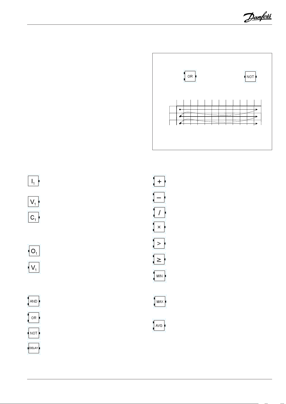
Function units
2
1
3
a
b
c
d
e
f
g
h
i
j
k
l
Depending on the type, a function unit can:
• Read an input value
• Perform a calculation
• Forward a value
• Save a set (constant) value
• Save a temporary value
• Activate an output
Contact points
A function unit may have several contact points, which function as
inputs and outputs depending on the type.
Signal path
The individual function units are assembled to form a collective
function in a grid. Each function unit is executed one by one. Reading takes place from left to right and then down. (The program
runs through a complete line before it continues onto the next
line.)
Inputs
Input signal
E.g. a temperature on an input, a digital signal or the
signal from a function.
Internal variable where a temporary calculation can be
used. (Boolean or oating point value)
Internal constant (Boolean or oating point value)
Examples
Inputs Input
A
B
Output
C
Mathematical calculations
Addition
C = A + B
Subtraction
C = A - B
Division
C = A / B
Output
A
B
Output
Output
E.g. a function, a voltage signal or a relay
Internal variable where a temporary calculation can be
saved. (Boolean or oating point value)
Logical calculations
And
C = A AND B
OR
C = A OR B
NOT
B = NOT A
DELAY
Delays a “TRUE” signal for a number of seconds.
The delay period starts every time the input becomes
”TRUE”.
The input must be ”TRUE” throughout the entire delay
period in order for the output to become ”TRUE”.
Multiplication
C = A x B
Greater than
If A > B then C = TRUE, else C = FALSE
Greater than or equal to
If A >= B then C = TRUE, else C = FALSE
Min.
The smaller value of two input values is reproduced on
the output
If A > B then C = B, else C = A
Max.
The larger value of two input values is reproduced on
the output
If A > B then C = A, else C = B
Avg.
The average of two input values is reproduced on the
output.
C = ( A + B) /2
AK-SM 720 — Boolean logic User guide RC8CA202 © Danfoss 02/2009 3

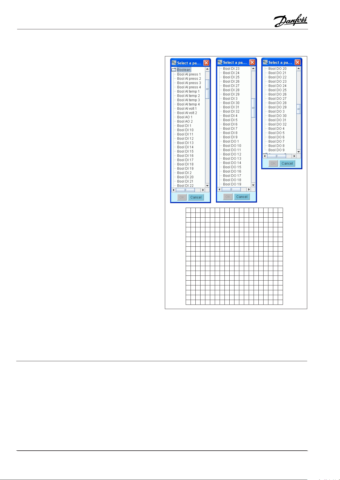
Conguration
Procedure:
1. Highlight a eld
2. Insert one of the elements that are shown in the left-hand column (if you select the wrong element, or later want to move the
elements around, you can overwrite an element by inserting the
”empty” element in place).
3. The settings for the element must then be made. These settings
are performed in the right-hand half of the screen. The next
page shows the various settings for the elements.
Constants can be changed during operation. Everything else
can only be changed when the logic is stopped.
4. Finally, the functions must be started when the conguration
has been completed. Press the ”Run” button at the top of the
screen.
At the bottom of the screen you can see the status of all
the dened elements.
Units for pressure and temperature
e.g. Bar, °C, Psig, °F
All settings and calculations are performed in bar and °C.
They can then be converted to a dierent unit at a later date.
4 User guide RC8CA202 © Danfoss 02/2009 AK-SM 720 — Boolean logic

There are dierent settings according to which element is dened.
• Select Input reference
• Type in name
• Select parameter
• Set “Refresh rate”
• Select Unit
• Press OK
• Remember also to set I/O conguration
The program will suggest the
next number in the series, but if
you want a dierent reference
you can change it here.
During I/O conguration, the position
of the connection must be dened.
• Select Output reference
• Type in name the name is also entered in the output
reference)
• Press OK
• Remember also to set I/O conguration
• Type in name
• Select unit
(if necessary)
• Press OK
During I/O conguration, the position
of the output must be dened.
• Type in name
• Select unit
• Set value
• Press OK
AK-SM 720 — Boolean logic User guide RC8CA202 © Danfoss 02/2009 5

Examples
Thermostat (heating and cooling)
• If the temperature becomes higher than the set tempera-
ture for cooling, the relay for cooling will be activated.
• If the temperature becomes lower than the set tempera-
ture for heating, the relay for heating will be activated.
Ref. Parameter Unit Value I/O
I
4
C
C
O
O
Delay 120 sec
Delay 180 sec.
Bool AI temp 1 Temp x.x
3
4
Bool DO 1 x.x
3
Bool DO 2 x.x
4
Temp 30
Temp 2
Set Heat
Temp
Set Cool
Heat
Cool
6 User guide RC8CA202 © Danfoss 02/2009 AK-SM 720 — Boolean logic

Convert a sensor signal to a voltage
P control with min/max limit
0
1
2
3
4
5
6
7
8
9
10
20
21
22
23
24
25
26
27
28
Temperature
Volt
Analog out
signal
I3 temperature (AI1)
C3 reference (22ºC)
C4 amplication (2)
C5 minimum lower voltage (1)
C6 maximum upper voltage (9)
O9 analog output 0-10 V (1-9 V)
Ref. Parameter Unit Value I/O
I
3
C
C
C
C
O
Bool AI temp 1 Temp x.x
3
4
5
6
Bool AO 1 x.x
9
Temp 22
None 2
None 1
None 9
AK-SM 720 — Boolean logic User guide RC8CA202 © Danfoss 02/2009 7

Danfoss can accept no responsibility for possible errors in catalogues, brochures and other printed material. Danfoss reserves the right to alter its products without notice. This also applies to products
already on order provided that such alternations can be made without subsequential changes being necessary in specications already agreed.
All trademarks in this material are property of the respecitve companies. Danfoss and Danfoss logotype are trademarks of Danfoss A/S. All rights reserved.
8 User guide RC8CA202 © Danfoss 02/2009 AK-SM 720 — Boolean logic
DE-BD
 Loading...