

Page 1

User Guide
Network control
AK-SM 720
ADAP-KOOL® Refrigeration control systems
www.danfoss.com
Page 2

User Guide | Network control AK-SM 720
Contents
1. Introduction
Application ................................................................................................. 3
Principles ..................................................................................................... 4
2. Design of a controller
Module survey .................................................................................................... 7
Common data for modules ............................................................................9
Dimensions ........................................................................................................10
System manager AK-SM.......................................................................11
Extension module AK-XM 101A ........................................................13
Extension module AK-XM 102A / AK-XM 102B ............................15
Extension module AK-XM 204A / AK-XM 204B ............................17
Extension module AK-XM 205A / AK-XM 205B ............................19
Extension module AK-XM 107A .......................................................21
Extension module AK-OB 110 ............................................................23
Power supply module AK-PS 075 / 150 ..........................................24
Preface to design .............................................................................................25
Functions ...................................................................................................25
Connections .............................................................................................26
Limitations ................................................................................................26
Design of a System manager ......................................................................27
Ordering .............................................................................................................35
3. Mounting and wiring
Mounting............................................................................................................36
Wiring ..................................................................................................................37
4. Configuration and operation
Installation in network...................................................................................39
Configuration ....................................................................................................41
Connect PC ...............................................................................................41
Unlock the configuration of the controllers .................................43
Clock function .........................................................................................44
Quick setup...............................................................................................45
Plants main data .....................................................................................46
Alarm relay on plant ..............................................................................47
Destinations to be communicated with ........................................48
Routing of alarms ...................................................................................49
Alarms from controllers .......................................................................51
Modem and IP settings ........................................................................52
Design some functions yourself .......................................................53
Alarms for boolean functions ............................................................54
AKC controllers on DANBUSS.............................................................55
Configuration of inputs and outputs ..............................................57
Set alarm priorities .................................................................................58
Lock configuration .................................................................................59
Check configuration ..............................................................................60
Check of connections ....................................................................................61
Find the controllers on the network .........................................................62
Setup of controllers ........................................................................................63
Setup functions ................................................................................................64
Logs ......................................................................................................................65
Plant operations ...............................................................................................67
First start of system manager ......................................................................81
Check alarms ............................................................................................81
Lock configuration of connections ..................................................82
Check level for safety ............................................................................83
Conclusion ................................................................................................83
5. Regulating function
Local data communication ..........................................................................85
Extern data communication ........................................................................86
Alarm handling ................................................................................................88
Plant controls ....................................................................................................90
Logs ......................................................................................................................94
Operation ...........................................................................................................96
Clock.....................................................................................................................97
2 | BC041586425769en-000602 © Danfoss | DCS (vt) | 2020.01
Page 3
User Guide | Network control AK-SM 720
1. Introduction
Application
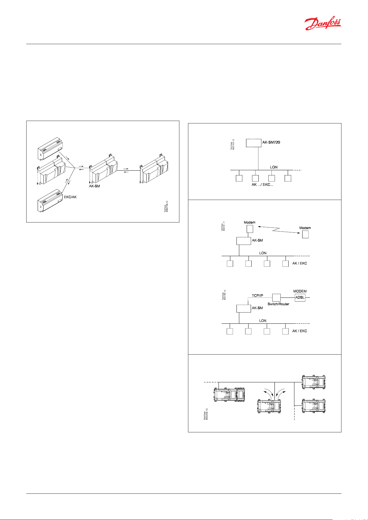
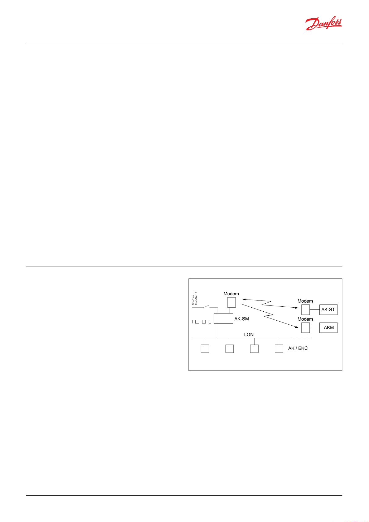
AK-SM 720 is a complete system manager to control data communication to ADAP-KOOL® Refrigeration Control Systems.
The system unit makes it possible to transmit alarms and system
functions to external receivers.
The main function of the system manager is to transmit alarms.
It also contains the primary functions that the refrigeration system’s controllers can use to sub-optimise the individual refrigeration sites.
To mention some of the various functions briefly:
• Alarm receiver
• Forward alarms
• Collect logs
• Schedules
• Defrost groups
• Light functions
• Energy-saving functions
• Design of Boolean functions
Examples
Here are a couple of examples where the system manager takes
care of communication to other units.
Receive alarms and logs from the controllers in the application
Modem connection to the service company
Local data communication can be:
• LON RS 485
• MODBUS
• DANBUSS (this does, however, also require a protocol interface
type AK-PI 200. Literature no. RS8EX)
• There is a maximum of 200 controllers on the data communication.
A maximum of 120 units of the EKC incl. SLV, where there must
be a maximum of 15 different types and software versions.
• TCP/IP
External data communication can be:
• TCP/IP
• Modem
Operation must take place using:
• Service tool type AK-ST
The system unit can transmit alarms and logs to:
• System software type AKM
© Danfoss | DCS (vt) | 2020.01 BC041586425769en-000602 | 3
Retrieve functions from some controllers and forward them to others
Page 4

User Guide | Network control AK-SM 720
Principles
The great advantage of this series of controllers is that it can
be extended as the size of the plant is increased. It has been
developed for refrigeration control systems, but not for any
specific application – variation is created through the read-in
software and the way you choose to define the connections.
It is the same modules that are used for each regulation and the
composition can be changed, as required. With these modules
(building blocks) it is possible to create a multitude of various
kinds of regulations. But it is you who must help adjusting the
regulation to the actual needs – these instructions will assist you
to find your way through all the questions so that the regulation
can be defined and the connections made.
Controller
Top part
Bottom part
The controller is the cornerstone of the regulation. The module has inputs and
outputs capable of handling small systems.
• The bottom part – and hence the terminals – are the same for all controller types.
• The top part contains the intelligence with software. This unit will vary according
to controller type. But it will always be supplied together with the bottom part.
• In addition to the software the top part is provided with connections for data
communication and address setting.
Advantages
• The controller’s size can “grow” as systems grow
• The software can be set for one or more regulations
• Several regulations with the same components
• Extension-friendly when systems requirements are changed
• Flexible concept:
- Controller series with common construction
- One principle – many regulation uses
- modules are selected for the actual connection requirements
- The same modules are used from regulation to regulation
Extension modules
If the system grows and more functions have to be controlled, the regulation can be
extended.
With extra modules more signals can be received and more relays cut in and out
– how many of them – and which – is determined by the relevant application.
Examples
A regulation with few connections can
be performed with the controller module
alone
If there are many connections one or more
extension modules have to be mounted
4 | BC041586425769en-000602 © Danfoss | DCS (vt) | 2020.01
Page 5
User Guide | Network control AK-SM 720
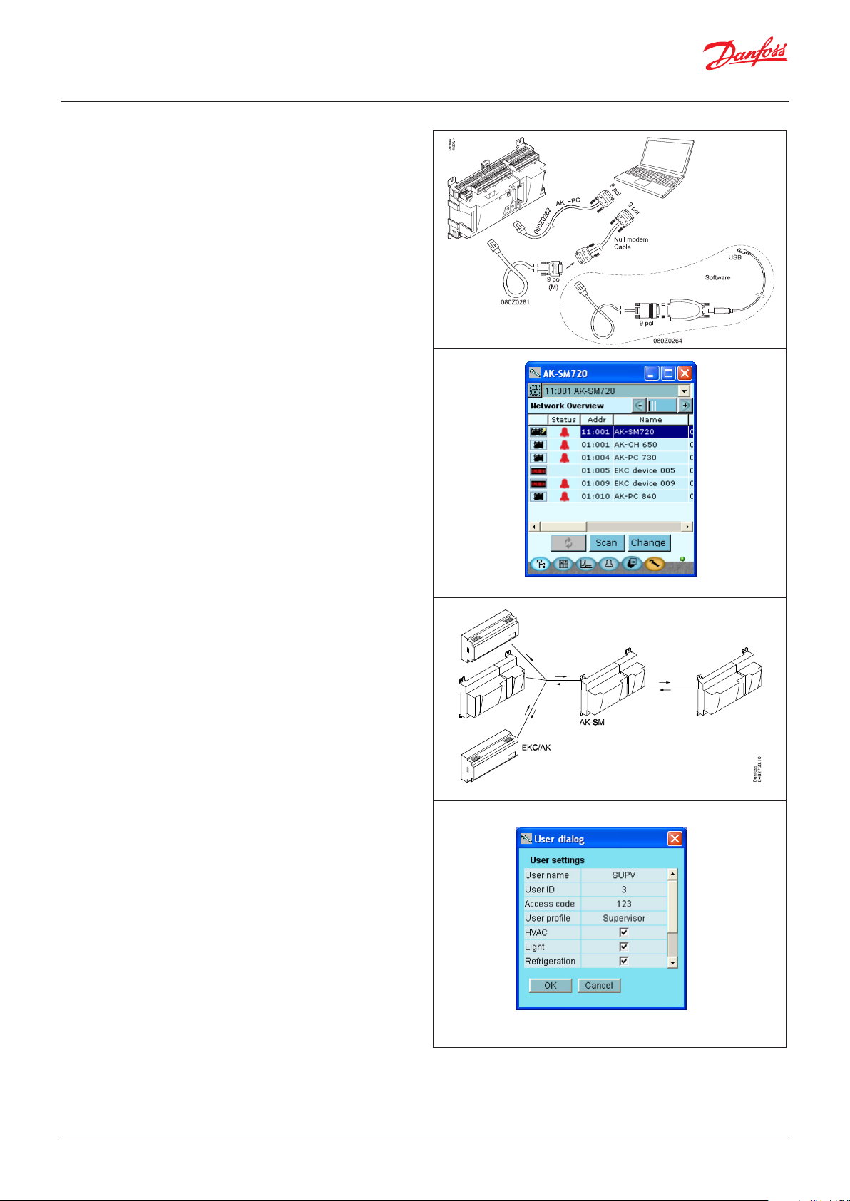
Direct connection
Setup and operation of an AK controller must be accomplished via
the “AK-Service Tool” software program.
The programme is installed on a PC, and setup and operation of
the various functions are carried out via the controller’s menu
displays.
Displays
The menu displays are dynamic, so that different settings in one
menu will result in different setting possibilities in other menus.
A simple application with few connections will give a setup with
few settings.
A corresponding application with many connections will give a
setup with many settings.
From the overview display there is access to further displays for
the compressor regulation and the condenser regulation.
At the bottom of the display there is access to a number of general
functions, such as "network overview", “time table”, “log function”,
“alarms”, "plant control" and “service” (configuration).
Data communication
The controller forwards the data communication to all of the
connected controllers. It receives measurements from selected
functions. The measurements are sent to other controllers, which
use the value in the control function.
The controller receives alarms from all connected controllers and
forwards them to the defined receivers.
Users
All users must be assigned a user profile which either gives access
to full operation or gradually limits the operation to the lowest
level that only allows you “to see”.
Users are added and defined in the menu item “Configuration”/
”Authorisation”.
© Danfoss | DCS (vt) | 2020.01 BC041586425769en-000602 | 5
Page 6

User Guide | Network control AK-SM 720
Light-emitting diodes
A number of light-emitting diodes makes it possible to follow the
signals that are received and transmitted by the controller.
Log
From the log function you can define the measurements you wish
to be shown.
The collected values can be printed, or you may export them to a
file. You can open the file in Excel.
If you are in a service situation you can show measurements in a
trend function. The measurements are then made realtime and
displayed instantly.
n Power
n Comm
n DO1 n Status
n DO2 n Alarm
n DO3 n Service Tool
n DO4 n LON
n DO5 n RS485
n DO6 n LAN
n DO7
n DO8 n Service Pin
Slow flash = OK
Quick flash = answer from master in 10 min.
after network installation
Constantly ON = error
Constantly OFF = error
Flash = Active alarm / not cancelled
Constant On = Aktive alarm / cancelled
External communication
Network installation
Alarm
The display gives you an overview of all active alarms. If you wish
to confirm that you have seen the alarm you can cross it off in the
acknowledge field.
If you want to know more about a current alarm you can click on it
and obtain an information display on the screen.
A corresponding display exists for all earlier alarms. Here you can
upload information if you need further details about the alarm
history.
6 | BC041586425769en-000602 © Danfoss | DCS (vt) | 2020.01
Page 7

User Guide | Network control AK-SM 720
2. Design of a controller
This section describes how the controller is designed.
The controller in the system is based on a uniform connection
platform where any deviations from regulation to regulation is
determined by the used top part with a specific software and
by which input and output signals the relevant application will
Module survey
• Controller module – capable of handling minor plant requirements.
• Extension modules. When the complexity becomes greater and
additional inputs or outputs are required, modules can be attached to the controller. A plug on the side of the module will
transmit the supply voltage and data communication between
the modules.
• Top part
The upper part of the controller module contains the intelligence.
This is the unit where the regulation is defined and where data
communication is connected to other controllers in a bigger
network.
• Connection types
There are various types of inputs and outputs. One type may, for
example, receive signals from sensors and switches, another may
receive a voltage signal, and a third type may be outputs with
relays etc. The individual types are shown in the table below.
require. If it is an application with few connections, the controller
module (top part with belonging bottom part) may be sufficient.
If it is an application with many connections it will be necessary to
use the controller module plus one or more extension modules.
This section will give you a survey of possible connections plus
assistance in selecting the modules required by your actual
application.
• Optional connection
When a regulation is planned (set up) it will generate a need for
a number of connections distributed on the mentioned types.
This connection must then be made on either the controller
module or an extension module. The only thing to be observed
is that the types must not be mixed (an analog input signal must
for instance not be connected to a digital input).
• Programming of connections
The controller must know where you connect the individual
input and output signals. This takes place in a later configuration where each individual connection is defined based on the
following principle:
- to which module
- at which point (”terminals”)
- what is connected (e.g. pressure transmitter/type/
pressure range)
Extension module with
additional analog inputs
Controller with analog inputs and
relay outputs.
Top part
Extension module with additional
relay outputs and additional
analog inputs.
The module with additional relay outputs is
also available in a version where the top part
is provided with change-over switches so
that the relays can be overridden.
Extension module with
analog output signals
© Danfoss | DCS (vt) | 2020.01 BC041586425769en-000602 | 7
Page 8
User Guide | Network control AK-SM 720
1. Controller
Type Function Application
AK-SM 720 System manager Control data communication
2. Extension modules and survey of inputs and outputs
Type Analog
inputs
For sensors,
pressure transmitters etc.
System manager 11 4 4 - - - - -
Extension modules
AK-XM 101A 8
AK-XM 102A 8
AK-XM 102B 8
AK-XM 204A 8
AK-XM 204B 8 x
AK-XM 205A 8 8
AK-XM 205B 8 8 x
AK-XM 107A 8
The following extension module can be placed on the PC board in the controller module.
There is only room for one module.
AK-OB 110 2
On/Off outputs On/off supply voltage
Relay
(SPDT)
Solid state Low voltage
(DI signal)
(max. 80 V)
High voltage
(max. 260 V)
Pulse counter
Low voltage
(max 30 V)
Analog
outputs
0 – 10 V DC For override of
Module with
switches
relay outputs
3. AK operation and accessories
Type Function Application
Operation
AK-ST 500 Software for operation of AK controllers AK-operation
- Cable between PC and AK controller AK - Com port
- Cable between zero modem cable and AK controller AK - RS 232
Accessories Power supply modul 230 V / 115 V to 24 V DC
AK-PS 075 18 VA DC
AK-PS 150 36 VA DC
Supply for controller
On the following pages there is data specific to each module.
8 | BC041586425769en-000602 © Danfoss | DCS (vt) | 2020.01
Page 9
User Guide | Network control AK-SM 720
Common data for modules
Supply voltage 24 V DC/AC +/- 20%
Power consumption AK-SM 720 8 VA
AK-XM 101, 102, 107 2 VA
AK-XM 204, 205 5 VA
Analog inputs Pt 1000 ohm /0 °C Resolution: 0.1 °C
Pressure transmitter type AKS 32R /
AKS 32 (1 – 5 V)
Voltage signal 0 – 10 V
Contact function (On/Off) On at R < 20 ohm
On/off supply voltage inputs Low voltage
Relay outputs
SPDT
Solid state outputs Can be used for loads that are cut in and
0 / 80 V AC/DC
High voltage
0 / 260 V AC
AC-1 (ohmic) 4 A
AC-15 (inductive) 3 A
U Min. 24 V
out frequently, e.g. :
rail heat, fans and AKV valve
Accuracy: +/- 0.5 °C
Resolution: 1 mV
Accuracy +/- 10 mV
Max. connection of 5 pressure transmitters on one module
Off at R > 2K ohm
(Gold -plated contacts not necessary)
Off: U < 2 V
On: U > 10 V
Off: U < 24 V
On: U > 80 V
Max. 230 V
Low and high voltage must not be connected to the same
output group
Max. 240 V AC , Min. 48 V AC
Max. 0.5 A,
Leak < 1 mA
Max. 1 AKV
Ambient temperature During transport -40 – 70 °C
During operation -20 – 55 °C ,
0 – 95% RH (non condensing)
No shock influences / vibrations
Enclosure Material PC / ABS
Density IP10 , VBG 4
Mounting For mounting on panel wall or DIN rail
Weight with screw terminals Modules in100- / 200- / controller-series Ca. 200 g / 500 g / 600 g
Approvals EU low voltage directive and EMC require-
ments are complied with
The mentioned data applies to all modules.
If data is specific, this is mentioned together with the module in question.
LVD tested according to EN 60730
EMC tested
Immunity according to EN 61000-6-2
Emission according to EN 61000-6-3
© Danfoss | DCS (vt) | 2020.01 BC041586425769en-000602 | 9
Page 10

User Guide | Network control AK-SM 720
Dimensions
The module dimension is 72 mm.
Modules in the 100-series consist of one module
Modules in the 200-series consist of two
modules
Controllers consist of three modules
The length of an aggregate unit = n x 72 + 8
A power supply module is either 36 mm or 54
mm
If there is space on the DIN rail, the power supply module can be positioned to the left of the
system manager.
10 | BC041586425769en-000602 © Danfoss | DCS (vt) | 2020.01
Page 11
User Guide | Network control AK-SM 720
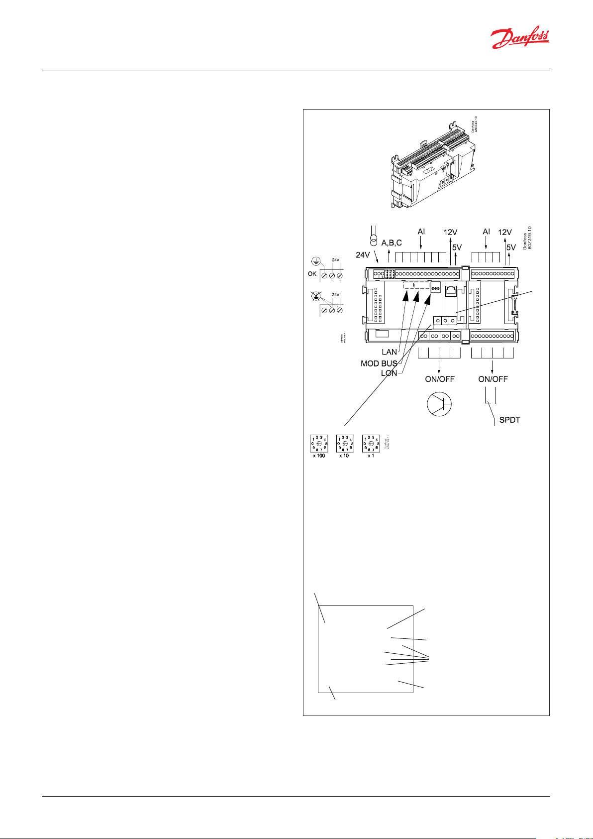
System manager AK-SM
Function
There are several controllers in the series. The function is
determined by the programmed software, but outwardly the
controllers are identical – they all have the same connection
possibilities:
11 analog inputs for sensors, pressure transmitters, voltage signals
and contact signals.
8 digital outputs, with 4 Solid state outputs and 4 relay outputs
Supply voltage
24 V AC or DC to be connected to the controller.
The 24 V must not be retransmitted and used by other controllers
as it is not galvanically separated from inputs and outputs. In
other words, you must use a transformer for each controller. Class
II is required. The terminals must not be earthed.
The supply voltage to any extension modules is transmitted via
the plug on the right-hand side.
The size of the transformer is determined by the power
requirement of the total number of modules.
The supply voltage to a pressure transmitter can be taken either
from the 5 V output or from the 12 V output depending on
transmitter type.
PIN
Data communication
The installation has to be made as mentioned in the separate
instructions.
Address setting
When the system manager is configured, the address must be set
in the range 1 to 10. 1 must always be used. If there are more than
one, the rest must be set with addresses 2 to 10.
Service PIN
When the address has been set, the software must know the setting. This is done by pressing the Service PIN button. The “Status”
LED will flash when acceptance is received.
Operation
The configuration operation of the controller must take place from
the software programme “Service Tool”. The program must be
installed on a PC, and the PC must be connected to the controller
via the network plug on the front of the unit.
Light-emitting diodes
There are two rows with LED’s. They mean:
Left row:
• Voltage supply to the controller
• Communication active with the bottom PC board (red = error)
• Status of outputs DO1 to DO8
Right row:
• Software status
• Alarm when LED flashes. Alarm acknowledged = constant light
• Communication with Service Tool
• Communication on LON
• Communication on MODBUS
• Communication on TCP/IP
• “Service Pin” switch has been activated
Address
Internal communication
between the moduls:
Quick flash = error
Constantly On = error
n Power
n Comm
n DO1 n Status
n DO2 n Alarm
n DO3 n Service Tool
n DO4 n LON
n DO5 n MODBUS
n DO6 n LAN
n DO7
n DO8 n Service Pin
Status on output 1-8
Slow flash = OK
Quick flash = answer from master in 10 min.
after network installation
Constantly ON = error
Constantly OFF = error
Flash = Active alarm / not cancelled
Constant On = Active alarm / cancelled
External communication
Network installation
Keep the safety
distance!
Low and high
voltage must not
be connected to
the same output
group
A small module (option board) can be placed on the bottom part
of the controller. The module is described later in the document.
© Danfoss | DCS (vt) | 2020.01 BC041586425769en-000602 | 11
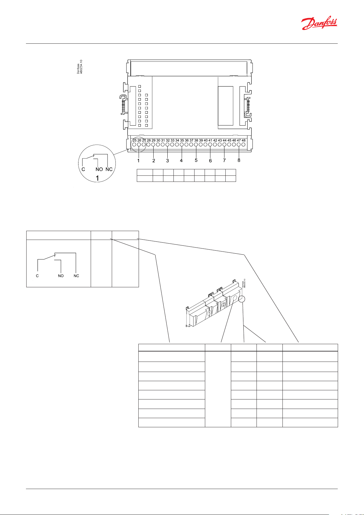
Page 12

User Guide | Network control AK-SM 720
Point
Analog
inputs
on 1 - 11
Solid state outputs
on 12 - 15
Relay or AKV coil
fx 230 V AC
S
Pt 1000 ohm/0°C
Point 1 2 3 4 5 6 7 8 9 10 11
Type AI1 AI2 AI3 AI4 AI5 AI6 AI7 AI8 AI9 AI10 AI11
Signal Signal
type
S1
S2
Saux1
Pt 1000
Saux2
SSA
SdA
24 and 25 used
only when "Option board fitted"
Terminal 15 & 27: 12 V
max. 100 mA in total.
Terminal 16 & 28: 5 V
max 100 mA in total.
Terminal
17, 18, 29, 30:
(Cable screen)
Relay outputs on
16 - 19
Point 12 13 14 15 16 17 18 19
Type DO1 DO2 DO3 DO4 DO5 DO6 DO7 DO8
P
AKS 32R
3: Brown
2: Blue
1: Black
P0A
P0B
PcA
PcB
AKS 32
3: Brown
2: Black
1: Red
U
...
On/Off Ext.
Main
switch
Day/
Night
Door
DO
AKV
AKV
Comp 1
Comp 2
Fan 1
Alarm
Light
Rail heat
Defrost
Option Board
Please see the signal
on the page with the
module.
AKS 32R
-1 - xx bar
AKS 32
-1 - zz bar
0 – 5 V
0 – 10 V
Active at:
Closed
/
Open
Active at:
On
/
Off
Signal Module Point Terminal Signal type / Active at
1 (AI 1) 1 - 2
2 (AI 2) 3 - 4
3 (AI 3) 5 - 6
4 (AI 4) 7 - 8
5 (AI 5) 9 - 10
6 (AI 6) 11 - 12
7 (AI 7) 13 - 14
8 (AI 8) 19 - 20
9 (AI 9) 21 - 22
10 (AI 10) 23 - 24
11 (AI 11) 25 - 26
1
12 (DO 1) 31 - 32
13 (DO 2) 33 - 34
14 (DO 3) 35 - 36
15 (DO 4) 37 - 38
16 (DO 5) 39 - 41
17 (DO6) 42 - 44
18 (DO7) 45 - 47
19 (DO8) 48 - 50
24 -
25 -
12 | BC041586425769en-000602 © Danfoss | DCS (vt) | 2020.01
Page 13

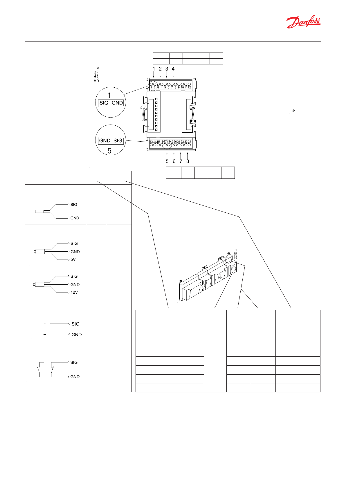
User Guide | Network control AK-SM 720
Extension module AK-XM 101A
Function
The module contains 8 analog inputs for sensors, pressure
transmitters, voltage signals and contact signals.
Supply voltage
The supply voltage to the module comes from the previous
module in the row.
Supply voltage to a pressure transmitter can be taken from either
the 5 V output or the 12 V output depending on transmitter type.
Light-emitting diodes
Only the two top LED’s are used. They indicate the following:
• Voltage supply to the module
• Communication with the controller is active (red = error)
© Danfoss | DCS (vt) | 2020.01 BC041586425769en-000602 | 13
Page 14
User Guide | Network control AK-SM 720
Point
S
Pt 1000 ohm/0°C
At the top the
signal input is
the left of the
two terminals.
At the bottom
the signal input
is the right of the
two terminals.
Signal Signal
S1
S2
Saux1
Saux2
SSA
SdA
type
Pt 1000
Point 1 2 3 4
Type AI1 AI2 AI3 AI4
Point 5 6 7 8
Type AI5 AI6 AI7 AI8
Terminal 9 & 16: 12 V max.
100 mA in total.
Terminal 10 & 15: 5 V max
100 mA in total.
Terminal
11, 12, 13, 14:
(Cable screen)
P
AKS 32R
AKS 32
3: Brown
2: Blue
1: Black
3: Brown
2: Black
1: Red
P0A
P0B
PcA
PcB
U
...
On/Off Ext.
Main
switch
Day/
Night
Door
AKS 32R
-1 - xx bar
AKS 32
-1 - zz bar
0 – 5 V
0 – 10 V
Active at:
Closed
/
Open
Signal Module Point
1 (AI 1) 1 - 2
2 (AI 2) 3 - 4
3 (AI 3) 5 - 6
4 (AI 4) 7 - 8
5 (AI 5) 17 - 18
6 (AI 6) 19 - 20
7 (AI 7) 21 - 22
8 (AI 8) 23 - 24
Terminal
Signal type /
Active at
14 | BC041586425769en-000602 © Danfoss | DCS (vt) | 2020.01
Page 15

User Guide | Network control AK-SM 720
Extension module AK-XM 102A / AK-XM 102B
Function
The module contains 8 inputs for on/off voltage signals.
Signal
AK-XM 102A is for low voltage signals.
AK-XM 102B is for high voltage signals.
Supply voltage
The supply voltage to the module comes from the previous
module in the row.
Light-emitting diodes
They indicate:
• Voltage supply to the module
• Communication with the controller is active (red = error)
• Status of the individual inputs 1 to 8 (when lit = voltage)
AK-XM 102A
Max. 24 V
On/Off:
On: DI > 10 V AC
Off: DI < 2 V AC
AK-XM 102B
Max. 230 V
On/Off:
On: DI > 80 V AC
Off: DI < 24 V AC
© Danfoss | DCS (vt) | 2020.01 BC041586425769en-000602 | 15
Page 16
User Guide | Network control AK-SM 720
Point
DI
AK-XM 102A: Max. 24 V
AK-XM 102B: Max. 230 V
Signal Active at
Ext.
Main
switch
Day/
Night
Comp.
safety 1
Comp.
safety 2
Closed
(voltage on)
/
Open
(voltage off)
Point 1 2 3 4
Type DI1 DI2 DI3 DI4
Point 5 6 7 8
Type DI5 DI6 DI7 DI8
Signal Module Point Terminal Active at
1 (DI 1) 1 - 2
2 (DI 2) 3 - 4
3 (DI 3) 5 - 6
4 (DI 4) 7 - 8
5 (DI 5) 9 - 10
6 (DI 6) 11 - 12
7 (DI 7) 13 - 14
8 (DI 8) 15 - 16
16 | BC041586425769en-000602 © Danfoss | DCS (vt) | 2020.01
Page 17
User Guide | Network control AK-SM 720
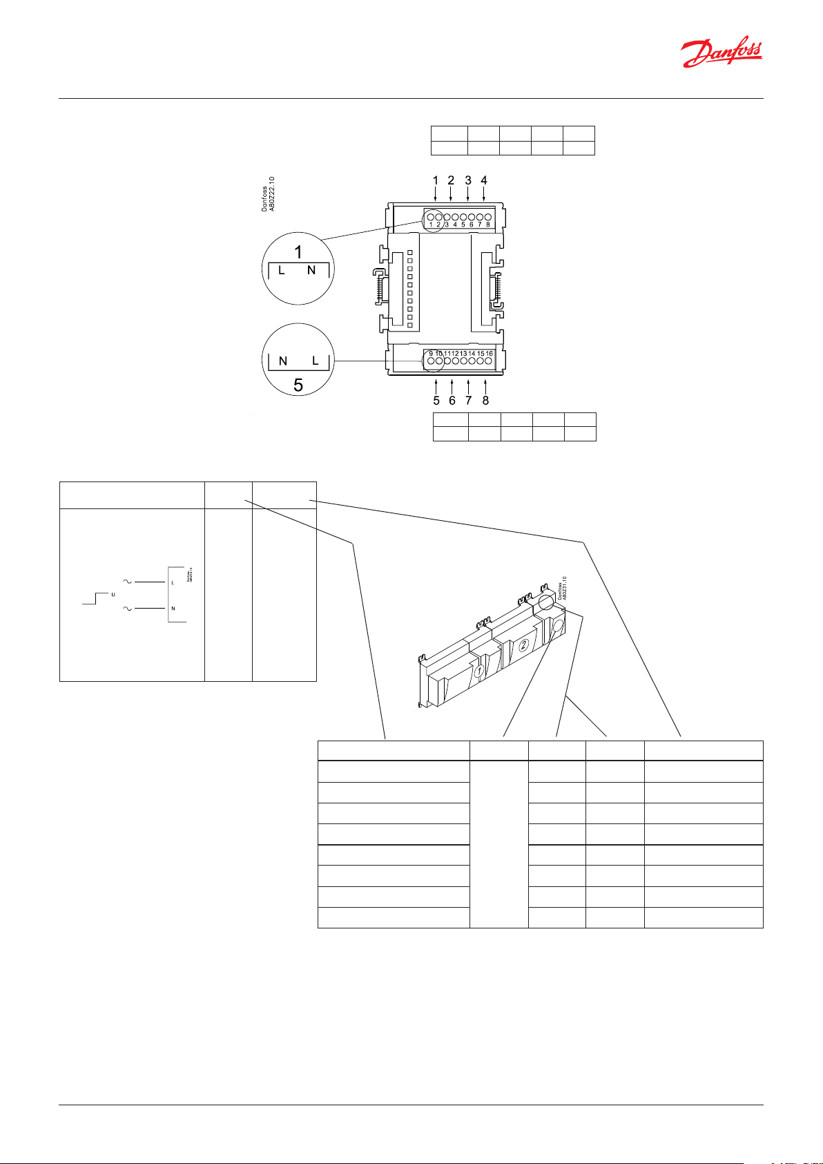
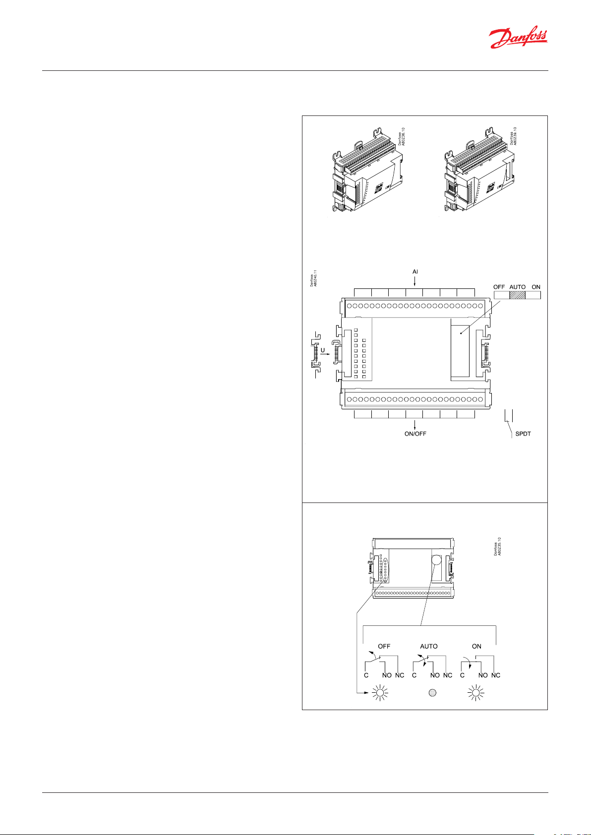
Extension module AK-XM 204A / AK-XM 204B
Function
The module contains 8 relay outputs.
Supply voltage
The supply voltage to the module comes from the previous
module in the row.
AK-XM 204B only
Override of relay
Eight change-over switches at the front make it possible to
override the relay’s function.
Either to position OFF or ON.
In position Auto the controller carries out the control.
Light-emitting diodes
There are two rows with LED’s. They indicate the following:
Left row:
• Voltage supply to the controller
• Communication active with the bottom PC board (red = error)
• Status of outputs DO1 to DO8
Right row: (AK-XM 204B only):
• Override of relays
Light ON = override
Light OFF = no override
AK-XM 204A AK-XM 204B
Fuses
Behind the upper part there is a fuse for each output.
Max. 230 V
AC-1: max. 4 A (ohmic)
AC-15: max. 3 A (Inductive)
AK-XM 204B
Override of relay
Keep the safety distance!
Low and high voltage
must not be connected to
the same output group
© Danfoss | DCS (vt) | 2020.01 BC041586425769en-000602 | 17
Page 18
User Guide | Network control AK-SM 720
Point
Punkt 1 2 3 4 5 6 7 8
Type DO1 DO2 DO3 DO4 DO5 DO6 DO7 DO8
DO
Signal Active at
Comp. 1
Comp. 2
Fan 1
Alarm
On
/
Off
Signal Module Point Terminal Active at
1 (DO 1) 25 - 27
2 (DO 2) 28 - 30
3 (DO 3) 31 - 33
4 (DO 4) 34 -36
5 (DO 5) 37 - 39
6 (DO 6) 40 - 42
7 (DO 7) 43 - 45
8 (DO 8) 46 - 48
18 | BC041586425769en-000602 © Danfoss | DCS (vt) | 2020.01
Page 19
User Guide | Network control AK-SM 720
Extension module AK-XM 205A / AK-XM 205B
Function
The module contains:
8 analog inputs for sensors, pressure transmitters, voltage signals
and contact signals.
8 relay outputs.
Supply voltage
The supply voltage to the module comes from the previous
module in the row.
AK-XM 205B only
Override of relay
Eight change-over switches at the front make it possible to
override the relay’s function.
Either to position OFF or ON.
In position Auto the controller carries out the control.
Light-emitting diodes
There are two rows with LED’s. They mean:
Left row:
• Voltage supply to the controller
• Communication active with the bottom PC board (red = error)
• Status of outputs DO1 to DO8
Right row: (AK-XM 205B only):
• Override of relays
ON = override
OFF = no override
AK-XM 205A AK-XM 205B
max. 10 V
Fuses
Behind the upper part there is a fuse for each output.
Max. 230 V
AC-1: max. 4 A (ohmic)
AC-15: max. 3 A (Inductive)
AK-XM 205B
Override of relay
Keep the safety distance!
Low and high voltage
must not be connected to
the same output group
© Danfoss | DCS (vt) | 2020.01 BC041586425769en-000602 | 19
Page 20

User Guide | Network control AK-SM 720
Point
S
Pt 1000 ohm/0°C
Signal Signal
type
S1
S2
Saux1
Pt 1000
Saux2
SSA
SdA
Point 1 2 3 4 5 6 7 8
Type AI1 AI2 AI3 AI4 AI5 AI6 AI7 AI8
Terminal 9 & 21: 12 V max.
100 mA in total.
Terminal 10 & 22: 5 V max
100 mA in total.
Terminal 11, 12, 23, 24 :
(Cable screen)
Point 9 10 11 12 13 14 15 16
Type DO1 DO2 DO3 DO4 DO5 DO6 DO7 DO8
P
AKS 32R
AKS 32
U
On/Off
DO
3: Brown
2: Blue
1: Black
3: Brown
2: Black
1: Red
P0A
P0B
PcA
PcB
...
Ext.
Main
switch
Day/
Night
Door
Comp 1
Comp 2
Fan 1
Alarm
Light
Rail
heat
Defrost
AKS 32R
-1 - xx bar
AKS 32
-1 - zz bar
0 – 5 V
0 – 10 V
Active at:
Closed
/
Open
Active at:
on
/
Off
Signal Module Point
1 (AI 1) 1 - 2
2 (AI 2) 3 - 4
3 (AI 3) 5 - 6
4 (AI 4) 7 - 8
5 (AI 5) 13 - 14
6 (AI 6) 15 - 16
7 (AI 7) 17 - 18
8 (AI 8) 19 -20
9 (DO 1) 25 - 27
10 (DO 2) 28 - 30
11 (DO 3) 31 - 33
12 (DO 4) 34 - 36
13 (DO 5) 37 - 39
14 (DO6) 40 - 42
15 (DO7) 43 - 45
16 (DO8) 46 - 48
Terminal
Signal type /
Active at
20 | BC041586425769en-000602 © Danfoss | DCS (vt) | 2020.01
Page 21
User Guide | Network control AK-SM 720
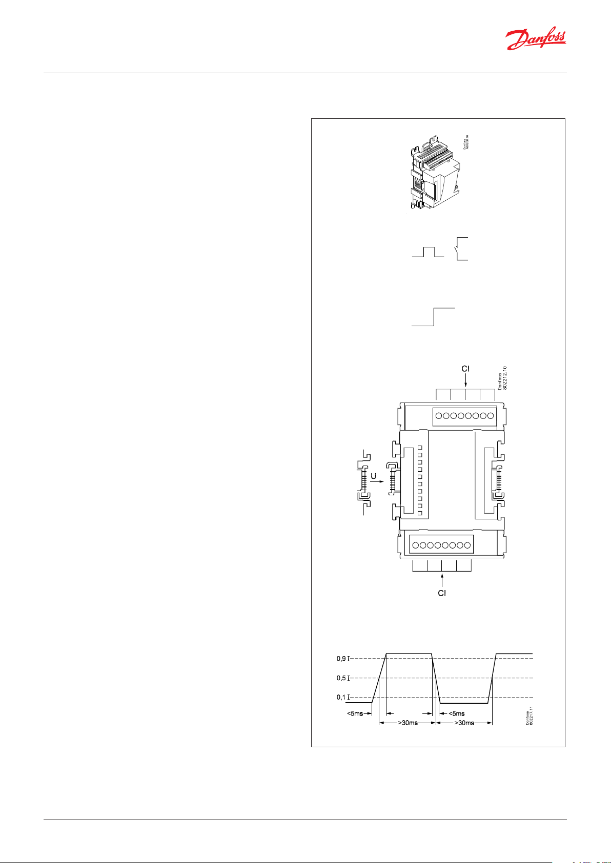
Extension module AK-XM 107A
Function
The module contains eight inputs for pulse counting. As an
alternative, the input can be used to register an On/Off signal. (DI
function).
Supply voltage
The supply voltage for the module comes from the previous module in the sequence.
LEDs
These indicate the following:
• Voltage of the module
• Communication with the controller is active (red = error)
(There is no LED indication for the individual signal inputs)
Signal
The signal is registered in accordance with DIN 43864.
Rise times and fall times must be less than 5 ms.
On and off times must be greater than 30 ms.
© Danfoss | DCS (vt) | 2020.01 BC041586425769en-000602 | 21
Page 22

User Guide | Network control AK-SM 720
Point
CI
Point 1 2 3 4
Type CI1 CI2 CI3 CI4
Point 5 6 7 8
Type CI5 CI6 CI7 CI8
Signal Active at
Puls - - -
Signal Module Point Terminal Active at
1 (CI 1) 1 - 2 - - 2 (CI 2) 3 - 4 - - 3 (CI 3) 5 - 6 - - 4 (CI 4) 7 - 8 - - 5 (CI 5) 9 - 10 - - 6 (CI 6) 11 - 12 - - 7 (CI 7) 13 - 14 - - 8 (CI 8) 15 - 16 - - -
22 | BC041586425769en-000602 © Danfoss | DCS (vt) | 2020.01
Page 23

User Guide | Network control AK-SM 720
Extension module AK-OB 110
Function
The module contains two analog voltage outputs of 0 – 10 V.
Supply voltage
The supply voltage to the module comes from the controller
module.
Placing
The module is placed on the PC board in the controller module.
Point
The two outputs have points 24 and 25. They are shown on the
earlier page where the controller is also mentioned.
Max. load
I < 2.5 mA
R > 4 kohm
AO
AO 0 – 10 V
Module
Point 24 25
Type AO1 AO2
1
AO2
AO1
© Danfoss | DCS (vt) | 2020.01 BC041586425769en-000602 | 23
Page 24

User Guide | Network control AK-SM 720
Power supply module AK-PS 075 / 150
Function
24 V supply for controller.
Supply voltage
100 V AC to 240 V AC 50/60Hz
Placing
On wall or DIN-rail
Effect
Type Output tension Output current Power
AK-PS 075 24 V DC 0.75 A 18 VA
AK-PS 150 24 V DC
(adjustable)
Dimension
Type High Width
AK-PS 075 90 mm 36 mm
AK-PS 150 90 mm 54 mm
1.5 A 36 VA
Connections
Supply to a System manager
AK-PS 075
AK-PS 150
24 | BC041586425769en-000602 © Danfoss | DCS (vt) | 2020.01
Page 25

User Guide | Network control AK-SM 720
Preface to design
In most cases the system manager may be able to manage the
control process without any kind of supplementary modules. Expansion modules will only be needed when measuring consumption, when using a large number of relays or when using Boolean
functions.
Be aware of the following when the number of extension modules
is being planned. A signal may have to be changed, so that an
additional module may be avoided.
• An ON/OFF signal can be received in two ways. Either as a contact
signal on an analog input or as voltage on a low or high-voltage
module.
Functions
Clock function
Clock function and change-over between summer time and winter time are contained in the system manager.
The clock’s setting is retained if there is a power failure.
Start/stop of regulation
Regulation can be started and stopped via the software. It cannot
be stopped with a switch function.
Alarm function
If the alarm is to be sent to a signal transmitter, a relay output will
have to be used.
System controls
Some of the possible system controls will require input signals or
output signals.
• Weekly schedule with the store’s hours of business
If there has to be an override to “day”, a switch function will be
required.
If there has to be an override to “night”, a switch function will be
required.
• An ON/OFF output signal can be given in two ways. Either with a
relay switch or with solid state. The primary difference is the permitted load and that the relay switch contains a cutout switch.
Mentioned below is a number of functions and connections
that may have to be considered when a regulation has to be
planned. There are more functions in the controller than the ones
mentioned here, but those mentioned have been included in
order that the need for connections can be established.
• Light control
A signal can be received from two light sensors. Each sensor
requires an analogue input.
Up to eight zones can be controlled. Each zone will require a
relay output or a triac output.
• Adaptive rail heat
A signal can be received from three dew point sensors. Each sensor requires two analogue inputs.
• Consumption measurement
When measuring consumption an expansion module must be
used for pulse counting.
A synchronisation signal will require an analogue or a digital
input.
A tariff signal will require an analogue or a digital input. Two
tariff signals can be received.
• Peak load limitation
This function requires a signal from a consumption measurement.
Up to ten relays can be connected.
• Weekly schedule for day/night operation
A switch signal will be required to override a schedule
• Weekly schedule for defrost
A switch signal will be required to override a schedule
• Weekly schedule for light
A switch signal will be required to override a schedule
• Inject ON function (closes the evaporator controls’ expansion valves
in the event of operational problems with the compressors)
The function can be enabled via data communication or it can
be wired outside the system manager
© Danfoss | DCS (vt) | 2020.01 BC041586425769en-000602 | 25
Data communication
The controller module has terminals for LON data communication.
The requirements to the installation are described in a separate
document.
Page 26

User Guide | Network control AK-SM 720
Connections
In principle there are the following types of connections:
Analog inputs ”AI”
This signal must be connected to two
terminals.
Signals can be received from the following
sources:
• Temperature signal from Pt 1000 ohm
temperature sensor
• Contact signal where the input is short-
circuited or ”opened”, respectively
• Voltage signal from 0 to 10 V
• Signal from pressure transmitter AKS 32
or AKS 32R
The supply voltage is supplied from the
module’s terminal board where there is
both a 5 V supply and a 12 V supply.
When programming the pressure
transmitter’s pressure range must be set.
ON/OFF voltage inputs ”DI”
This signal must be connected to two
terminals.
• The signal must have two levels, either 0 V
or ”voltage” on the input.
There are two different extension
modules for this signal type:
- low-voltage signals, e.g. 24 V
- high-voltage signals, e.g. 230 V
When programming the function must be set:
• Active when the input is without voltage
• Active when voltage is applied to the
input.
ON/OFF output signals ”DO”
There are two types, as follows:
• Relay outputs
All relay outputs are with change-over
relay so that the required function can be
obtained when the controller is without
voltage.
• Solid state outputs
Reserved for AKV valves, but output can
cut an external relay in and out, as with a
relay output.
The output is only found on the
controller module.
When programming the function must be set:
• Active when the output is activated
• Active when the output is not activated.
Analog output signal ”AO”
This signal is to be used if a control signal is
to be transmitted to an external unit, e.g. a
frequency converter.
When programming the signal range must
be defined: 0 – 5 V, 1 – 5 V, 0 – 10 V
or 2 – 10 V.
Pulse counter inputs
This signal must be used if consumption
measurement is to take place.
Limitations
As the system is very flexible regarding the number of connected
units you must check whether your selection complies with the
few limitations there are.
The complexity of the controller is determined by the software,
the size of the processor, and the size of the memory. It provides
the controller with a certain number of connections from which
data can be downloaded, and others where coupling with relays
can be performed.
There must a maximum of 200 controllers on the data communication.
A maximum of 120 units of the EKC type, where there must be a
maximum of 15 different types and software versions.
26 | BC041586425769en-000602 © Danfoss | DCS (vt) | 2020.01
• The sum of connections cannot exceed 80.
• The number of extension modules must be limited so that the
total power will not exceed 32 VA (including controller).
• No more than five pressure transmitters may be connected to
one controller module.
• No more than five pressure transmitters may be connected to
one extension module.
Page 27

User Guide | Network control AK-SM 720
Design of a System manager
Procedure:
1. Make a sketch of the system in question
2. Check that the controller’s functions cover the required
application
3. Consider the connections to be made
4. Use the planning table. / Note down the number of
connections. / add up
5. Are there enough connections on the controller module? – If
not, can they be obtained by changing an ON/OFF input signal
from voltage signal to contact signal, or will an extension
module be required?
6. Decide which extension modules are to be used
7. Check that the limitations are observed
8. Calculate the total length of modules
9. The modules are linked together
10. The connection sites are established
11. Draw a connection diagram or a key diagram
12. Size of supply voltage/power supply
1. Sketch
Make a sketch of the system in question
© Danfoss | DCS (vt) | 2020.01 BC041586425769en-000602 | 27
Page 28
User Guide | Network control AK-SM 720
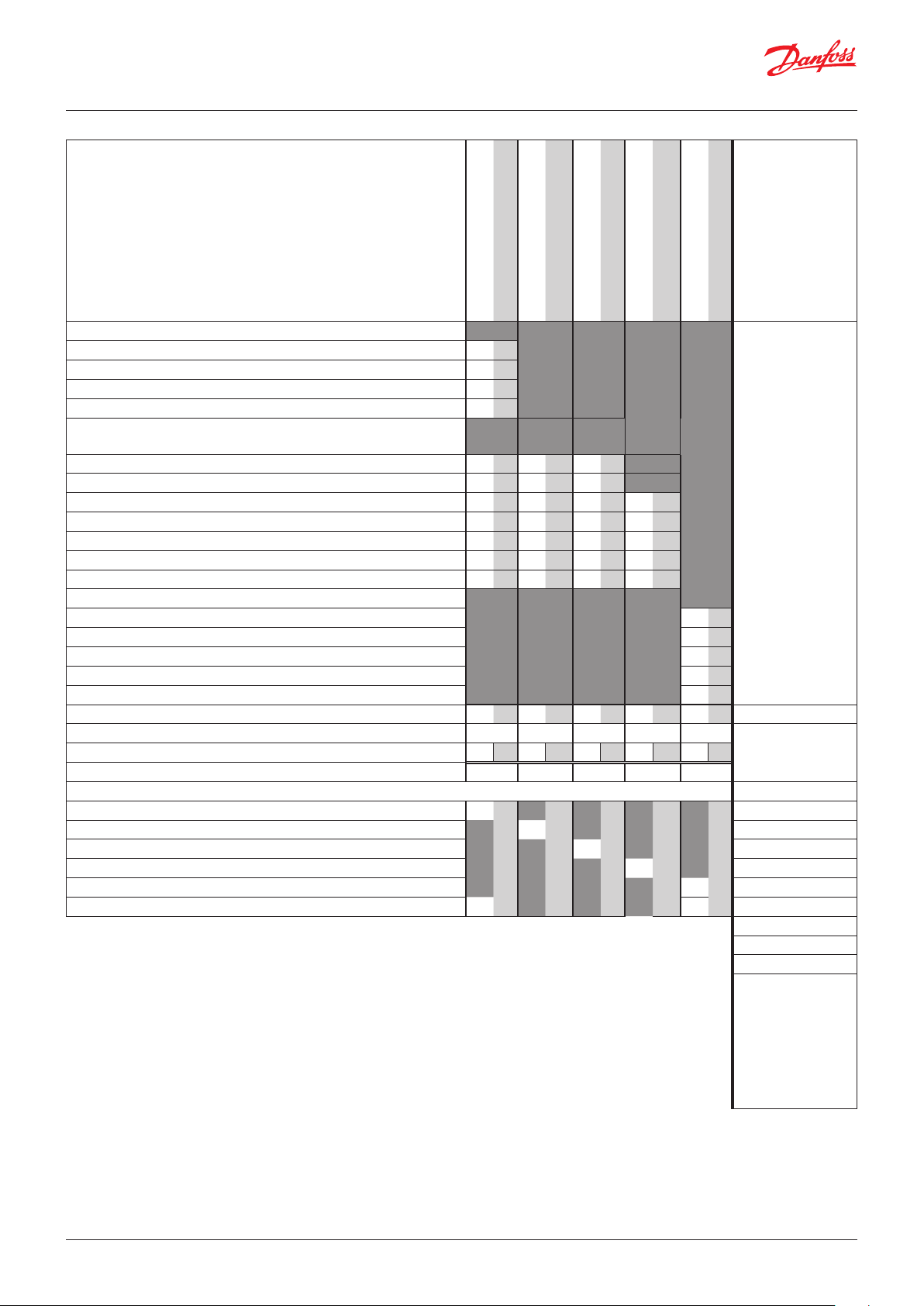
2. System functions
Application
Control of data communication on the refrigeration system
Control of data communication for external operation
Forward alarms and data collected x
Local data communication
LON RS485 together with
- Controllers type EKC
- Controllers type AK
- Frequency converter type AKD
MODBUS together with similar controllers that
have MODBUS communication
TCP/IP together with other AK-SM x
TCP/IP to AK-PI 200 and onwards to controllers
with DANBUSS
Max. number of controllers (addresses) in a
network
External data communication
Via modem and phone net x
Via TCP/IP and Internet x
200, although max.
120 EKC incl. SLV
x
x
x
x
x
User registration
User interface with Password and authorisation
levels
History Event x
Operation
Via PC and software type AK-ST x
Clock
Clock function with battery backup x
Resets the clock in the controllers after a power
failure
Safety
Communication control x
Watchdog function with adjustable interval time x
Data communication with "I'm a live" information x
High level of security against undesired user
access
x
x
x
A bit more about the functions ("2" continued)
Alarm management
LOG of alarms x
Routing of alarms to Systemsoftware x
A relay can be defined to an alarm relay x
System controls
Weekly schedule with the store’s hours of business x
Weekly schedules with time specified in relation to
hours of business
On/off control 5
Weekly schedules for use together with day/night
operation and start of defrost
Override weekly schedules with a switch function 10
Switch between day operation and night opera-
tion
Defrost start
Coordinated defrost (common start after defrost) x
Inject ON function (closes the evaporator controls’
expansion valves in the event of operational problems with the compressors)
P0-control 5 / 120 sections
Light control
Adaptive rail heat
Adaptive defrost
Consumption measurement 8
Load sheeding x
Synchronising signal x
max. 30 controllers
max. 30 controllers
x
10
Max. 20 groups of
Max. 20 groups of
5 / 120 sections
2 light sensors,
8 relais,
8 zones
3 groups /
30 sections
10 groups /
30 sections
Here is a little more about some of the functions that must use
an input or an output.
Modem connection
It is recommended that the supply voltage to the modem be
provided through a relay, so that the system manager can start the
modem in a controlled way.
The “Inject On” override function
This function closes expansion valves on evaporator controls when
all compressors have stopped.
The function can take place via data communication, or it can be
wired via a relay output on the compressor control.
Boolean functions
A function in the system unit makes it possible to set up some
logical functions. The functions can have both inputs and outputs.
The function is described in a separate document. Please refer to
literature sheet number RC8CA.
This setup of Boolean functions should only be undertaken by
trained personnel.
If you want to know more about the functions, go to chapter 5.
LOG
Stores LOG data from the connected controllers x
28 | BC041586425769en-000602 © Danfoss | DCS (vt) | 2020.01
Page 29
User Guide | Network control AK-SM 720
3. Connections
Here is a survey of the possible connections. The texts can be read
in context with the table on the next page.
Analog inputs
Temperature sensors
Up to 3 sensors for dew point measurement and 4 sensors for
boolean logic can be connected.
Pressure transmitter
A pressure transmitter type AKS 32 or AKS 32R can supply signals
to a maximum of five controllers.
Voltage signal
• 0 – 10 V
Used when signal is received from another control.
E.g. signal from dew point sensor. (A dew point sensor delivers
two signals – a temperature sensor signal and a voltage signal)
On/Off-inputs
Contact function (on an analog input)
or
Voltage signal (on an extension module)
• Switches to override a weekly schedule
• Switches to override light control
• Signal to register tariff levels
Pulse counter input (on an expansion module)
• E.g. for energy registration
On/off-outputs
Relay outputs
• Voltage supply to modem
• Watch dog function
• Injection On function (signal to evaporator control. One each
suction group)
• Alarm relay
• Light control
• Load sheeding
Solid state outputs
The solid state outputs on the controller module may be used
for the same functions as those mentioned under “relay outputs”.
(The output will always be “OFF” when the controller has a power
failure).
Example
• AK-SM 720 is with data communication for EKC controllers
• Modem connection for alarm routing (for System software AKM)
• Modem connection for external operation (for Service tool)
• Alarm output
• Contact to reset alarms
• Energy measurement, which receives puls signal from extern
unit.
Data from this example is used on the next page.
The result is that the following modules should be used:
• AK-SM 720 controller
• AK-XM 107A pulse module
© Danfoss | DCS (vt) | 2020.01 BC041586425769en-000602 | 29
Page 30
User Guide | Network control AK-SM 720
4. Planning table
The table helps you establish whether there are enough inputs
and outputs on the system manager.
If there are not enough of them, it must be extended by one or
more of the mentioned extension modules.
Note down the connections you will require and add them up
Analog inputs
Temperature signal from dew point sensor (max. 3)
Voltage signal from dew point sensor (max. 3)
Voltage signal from a light sensor (max. 2)
Analog input signal
Example
On/off voltage signal
Example
On/off voltage signal
Example
Pulse module
Example
On/Off output signal
Example
7
Limitations
On/off inputs Con-
tact
Contact for overriding of week schedule for day/night operation
Contact to overriding of weekly schedule for light
Pulse signal from meter for electr., gas, water etc. 1
On/Off signal about tariff change
Pulse pressure for stop of alarm 1
On/off outputs
Voltage supply for modem (reset function) 1
Alarm relay 1
Light zones (up to 8 relays)
5. Load sheeding limit (up to 10 relays)
6. Sum of connections 1 1 2 Sum = max. 80
Number of connections on a System manager 11 11 0 0 0 0 0 0 8 8
Missing connections, if applicable 0 - - 1 0
The missing connections to be supplied by one or more extension modules: Sum of power
AK-XM 101A (8 analog inputs) ___ pcs. á 2 VA = __
AK-XM 102A (8 digital low voltage inputs) ___ pcs. á 2 VA = __
AK-XM 102B (8 digital high voltage inputs) ___ pcs. á 2 VA = __
AK-XM 107A (8 pulse inputs) 1 ___ pcs. á 2 VA = __
AK-XM 204A / B (8 relay outputs) ___ pcs. á 5 VA = __
AK-XM 205A / B (8 analog inputs + 8 relay outputs) ___ pcs. á 5 VA = __
24 V 230 V
Pressure transmitters: Max. 5 each/
module
Boolean logic:
There are limitations to the number of functions.
Refer to separate
document RC8CA.
1 pcs. á 8 VA = 8
Sum =
Sum = max. 32 VA
Example:
None of the 3 limitations are exceeded
=> OK
30 | BC041586425769en-000602 © Danfoss | DCS (vt) | 2020.01
Page 31

User Guide | Network control AK-SM 720
8. Length
If you use many extension modules the controller’s length will
grow accordingly. The row of modules is a complete unit which
cannot be broken.
The module dimension is 72 mm.
Modules in the 100-series consist of one module
Modules in the 200-series consist of two modules
The controller consist of three modules
The length of an aggregate unit = n x 72 + 8
or in an other way:
Module Type Number at Length
Controller module 1 x 224 = 224 mm
Extension module 200-series _ x 144 = ___ mm
Extension module 100-series _ x 72 = ___ mm
Total length = ___ mm
9. Linking of modules
Example continued:
Controller module + Pulse module = 224 mm + 72 mm = 296 mm.
Start with the controller module and then mount the selected
extension modules. The sequence is of no importance.
However, you must not change the sequence, i.e. rearrange the
modules, after you have made the setup where the controller
is told which connections are found on which modules and on
which terminals.
The modules are attached to one another and kept together by a
connection which at the same time transmits the supply voltage
and the internal data communication to the next module.
Mounting and removal must always be performed when there is
no voltage.
The protective cap mounted on the controller’s plug connection
must be moved to the last vacant plug connection so that the
plug will be protected against short-circuit and dirt.
When the regulation has started the controller will all the time
check whether there is connection to the connected modules. This
status can be followed by the light-emitting diode.
When the two catches for the DIN rail mounting are in open
position the module can be pushed into place on the DIN rail – no
matter where in the row the module is found.
Removal is likewise carried out with the two catches in the open
position.
© Danfoss | DCS (vt) | 2020.01 BC041586425769en-000602 | 31
Page 32

User Guide | Network control AK-SM 720
10. Determine the connection points
All connections must be programmed with module and point, so
in principle it does not matter where the connections are made, as
long as it takes place on a correct type of input or output.
• The controller is the first module, the next one is 2, etc.
• A point is the two or three terminals belonging to an input or
output (e.g. two terminals for a sensor and three terminals for a
relay).
The preparation of the connection diagram and the subsequent
programming (configuration) should take place at the present
time. It is most easily accomplished by filling in the connection
survey for the relevant modules.
Principle:
Name On module On Point Function
fx Light 1 x x Close
fx Light 2 x x Close
fx Alarm relay x x NC
fx Modem x x Close
fx P0 x x AKS 32R 1-6 bar
The connection survey from the controller and any extension
modules are uploaded from the paragraph "Modules". See later in
the manual E.g. controller module:
Signal Module Point Terminal
1 (AI 1) 1 - 2
2 (AI 2) 3 - 4
3 (AI 3) 5 - 6
4 (AI 4) 7 - 8
Signal type /
Active at
Module Point
Mind the numbering.
The right-hand part of the
controller module may look like
a separate module. But it isn’t.
- Columns 1, 2, 3 and 5 are used for the programming.
- Columns 2 and 4 are used for the connection diagram.
Example continued:
Signal
Pulse pressure to set off the
alarm relay
Supply voltage to modem
Alarm relay for high priority
alarms
Mod-
ule
10 (AI 10) 23 - 24
11 (AI 11) 25 - 26
1
12 (DO 1) 31 - 32
13 (DO 2) 33 - 34
14 (DO 3) 35 - 36
15 (DO 4) 37 - 38
16 (DO 5) 39 - 41
17 (DO6) 42 - 44
18 (DO7) 45 - 47
19 (DO8) 48 - 50
Point Terminal
1 (AI 1) 1 - 2
2 (AI 2) 3 - 4
3 (AI 3) 5 - 6
4 (AI 4) 7 - 8
5 (AI 5) 9 - 10
6 (AI 6) 11 - 12
7 (AI 7) 13 - 14
8 (AI 8) 19 - 20
9 (AI 9) 21 - 22
24 -
25 -
Signal
type /
Active at
-
ON
OFF
Pulse signal
Signal
Mod-
ule
2
Point Terminal Active at
1 (CI 1) 1 - 2
2 (CI 2) 3 - 4
3 (CI 3) 5 - 6
4 (CI 4) 7 -8
5 (CI 5) 9 - 10
6 (CI 6) 11 - 12
7 (CI 7) 13 - 14
8 (CI 8) 15 - 16
- - -
- - -
- - -
- - -
- - -
- - -
- - -
- - -
32 | BC041586425769en-000602 © Danfoss | DCS (vt) | 2020.01
Page 33

User Guide | Network control AK-SM 720
11. Connection diagram
Drawings of the individual modules may be
ordered from Danfoss.
Format = dwg and dxf.
You may then yourself write the module
number in the circle and draw the individual
connections.
Example continued:
The modem connection is made
to this plug, but the plug is also
used by AK-ST 500.
So the modem plug can only be
positioned when all settings in
the system manager have been
completed.
© Danfoss | DCS (vt) | 2020.01 BC041586425769en-000602 | 33
Page 34

User Guide | Network control AK-SM 720
12. Supply voltage
Supply voltage is only connected to the controller module. The
supply to the other modules is transmitted via the plug between
the modules. The supply must be 24 V +/-20%. One power supply
must be used for each controller. The transformer must be a class
II. The 24 V must not be shared by other controllers or units. The
analog inputs and outputs are not galvanically separated from the
supply.
The + and – 24V input must not be earthed.
Example continued:
Controller module 8 VA
Pulse counter module 2 VA
------
Size of power supply 10 VA
Power supply size
The power consumption grows with the number of modules used:
Module Type Number á Effect
Controller 1 x 8 = 8 VA
Extension module 200-series _ x 5 = __ VA
Extension module 100-series _ x 2 = __ VA
Total ___ VA
34 | BC041586425769en-000602 © Danfoss | DCS (vt) | 2020.01
Page 35

User Guide | Network control AK-SM 720
Ordering
1. Controller
Type Function Application Language Code no.
AK-SM 720 System manager Control data communication
2. Extension modules and survey for inputs and outputs
Type Analog
inputs
On/Off outputs On/off supply voltage
(DI signal)
English, German, French,
Dutch, Italian
English (UK), Spanish, Portuguese, English (US)
English, Danish, Swedish,
Finnish
Analog
outputs
Module
with
switches
080Z8511 x
080Z8512
080Z8513
Code no.
Example
continued
Example
continued
For sensors,
pressure
transmitters
Relay
(SPDT)
Solid state Low voltage
(max. 80 V)
High voltage
(max. 260 V)
Pulse
counter
0 – 10 V DC For override
of relay
outputs
With screw
terminals
etc.
Controller 11 4 4 - - - - -
Extension modules
AK-XM 101A 8 080Z0007
AK-XM 102A 8 080Z0008
AK-XM 102B 8 080Z0013
AK-XM 204A 8 080Z0011
AK-XM 204B 8 x 080Z0018
AK-XM 205A 8 8 080Z0010
AK-XM 205B 8 8 x 080Z0017
AK-XM 107A 8 080Z0020 x
The following extension module can be placed on the PC board in the controller module.
There is only room for one module.
AK-OB 110 2 080Z0251
3. AK operation and accessories
Type Function Application Code no.
Operation
AK-ST 500 Software for operation of AK controllers AK-operation 080Z0161 x
- Cable between PC and AK controller AK - Com port 080Z0262 x
- Cable between zero modem cable and AK controller AK - RS 232 080Z0261
Example
continued
Accessories Power supply module 230 V / 115 V to 24 V DC
AK-PS 075 18 VA, 24 V DC
AK-PS 150
36 VA, 24 V DC 080Z0054
Supply for controller
080Z0053 x
Modem Please use a modem from Danfoss’s approved suppliers list. x
© Danfoss | DCS (vt) | 2020.01 BC041586425769en-000602 | 35
Page 36

User Guide | Network control AK-SM 720
3. Mounting and wiring
This section describes how the controller:
• Is fitted
• Is connected
Mounting
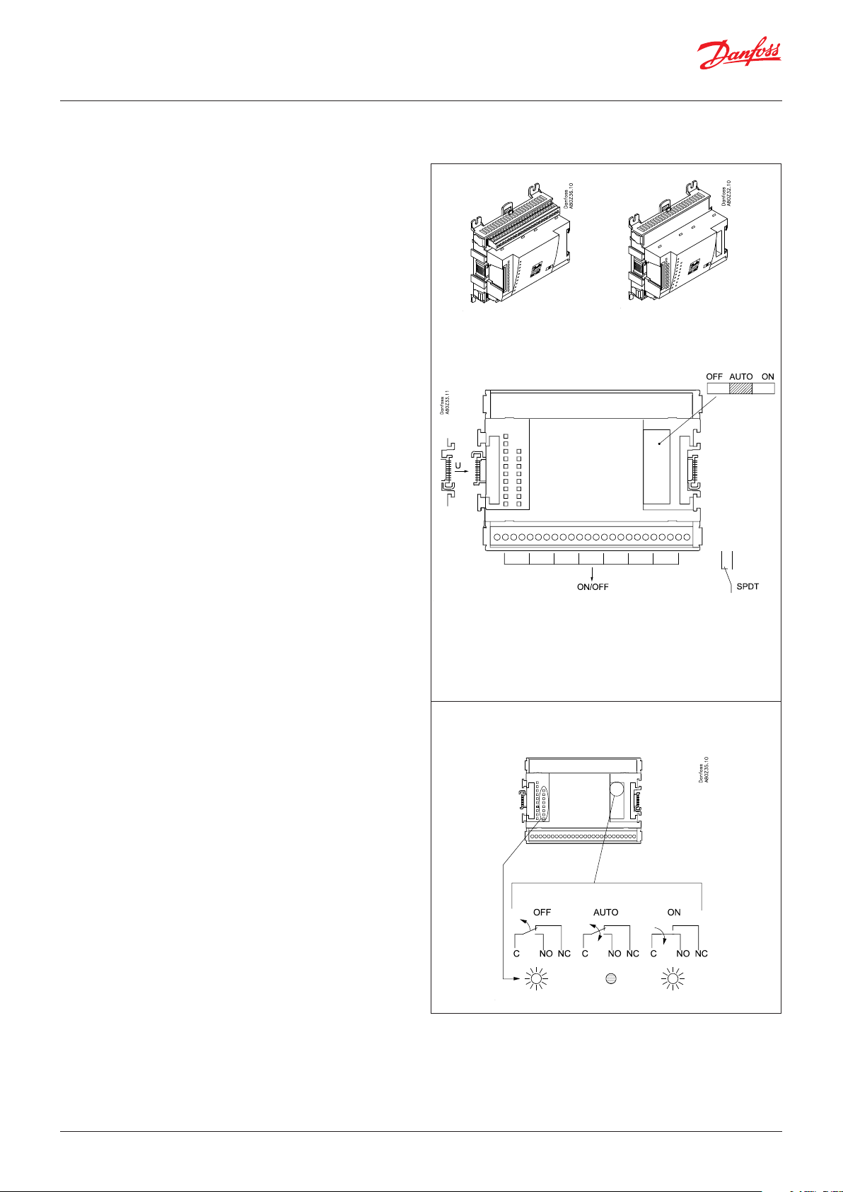
Mounting of extension module on the basic module
1. Move the protective cap
Remove the protective cap from the connection plug on the righthand side of the basic module.
Place the cap on the connection plug to the right of the I/O
module that is to be mounted on the extreme right-hand side of
the AK assembly.
We have decided to work on the basis of the example we went
through previously, i.e. the following modules:
• AK-SM 720 controller module
• AK-XM 107A pulse counter module
In our example one extension module is to be fitted to the basic
module.
All of the subsequent setting are determined by the module positions.
Here 1 and 2.
2. Assemble the I/O module and the basic module
The basic module must not be connected to voltage.
When the two snap catches for the DIN rail mounting are in the open
position, the module can be pushed into place on the DIN rail –
regardless of where the module is on the row.
Disassembly is thus done with the two snap catches in the open
position.
36 | BC041586425769en-000602 © Danfoss | DCS (vt) | 2020.01
Page 37

User Guide | Network control AK-SM 720
Wiring
Decide during planning which function is to be connected
and where this will be.
Here are the tables for the example:
1. Connect input and outputs
Signal Module Point
Pulse pressure for stopping
the alarm relay
Supply voltage to modem 16 (DO 5) 39 - 41 ON
Alarm relay for high priority
alarms
1 (AI 1) 1 - 2
1
17 (DO6) 42 - 44 OFF
Terminal
Signal type/
-
Active at
Important
Keep signal cables away from cables with high voltages.
Signal Module Point Terminal Active at
Pulse signal
2 1 (CI 1) 1 - 2
- - -
2. Connect LON and MODBUS communication network
Check that data communication is terminated at either end
3. Connect supply voltage
Is 24 V, and the supply must not be used by other controllers or
devices.
The two terminals must not be earthed.
4. Follow light-emitting diodes
When the supply voltage is connected the system manager will
go through an internal check. The controller will be ready in
just under one minute when the light-emitting diode ”Status”
starts flashing slowly.
5. When there is a network
Set the address and activate the Service Pin. See next
paragraph
6. The system manager is now ready for configuration.
The installation of the data communication must comply
with the requirements set out in document RC8AC.
Internal communication between the
modules:
Quick flash = error
Constantly On = error
n Power
n Comm
n DO1 n Status
n DO2 n Alarm
n DO3 n Service Tool
n DO4 n LON
n DO5 n MODBUS
n DO6 n LAN
n DO7
n DO8 n Service Pin
Status on output 1-8
Slow flash = OK
Quick flash = answer from gateway
in 10 min. after network installation
Constantly ON = error
Constantly OFF = error
Flash = active alarm/not cancelled
Constant ON = Active alarm/cancelled
External communication
Network installation
© Danfoss | DCS (vt) | 2020.01 BC041586425769en-000602 | 37
Page 38

User Guide | Network control AK-SM 720
4. Configuration and operation
This section describes how the controller:
• Is configured
• Is operated
Plant example
We have decided to describe the setup by means of an example
comprising a system manager and a number of controllers.
The example is the same as the one given in the "Design" section,
i.e. the system manager and one extension module.
Controllers:
• The controllers are of types AK- and EKC
• They are connected in a LON network
• They transmit alarms to the system manager
We have decided to work on the basis of the example we went
through previously.
The example is shown overleaf.
Modem:
• The modem is a type from the positive list
• It is connected to the system manager (it cannot be connected
until the setup has been completed as it is the same plug that is
used)
Operation:
• The setup is performed on the plant with PC and software
programme AK-ST
• After the setup operation can also take place via the modem and
AK-ST
Alarms:
• The alarm destination is System software type AKM at the
external modem
Alarm routing:
• To System software type AKM at the external modem
Controls:
• A table is set up for the shop’s opening hour
• Logs are collected in the system manager
• Logs are downloaded from the system manager with AKM
• Day/night hours for the refrigeration appliances are managed by
the system manager
• Defrost start is carried out by the system manager
• Consumption measurement (pulse signal is received from an
external unit)
• Switch to override the day/night schedule
• Switch (pulse pressure) to reset alarm
In the example the same modem will be used by both system software
type AKM and by Service tool type AK-ST.
This can only be achieved when it is possible to switch between the
two operating interfaces,
i.e. only one single destination is created.
If, however, it is not possible to switch, two destinations must be created, one for each modem.
38 | BC041586425769en-000602 © Danfoss | DCS (vt) | 2020.01
Page 39

User Guide | Network control AK-SM 720
Installation in network
1. Set net number
In our example the system manager must have address 1.
Turn the right-hand address switch so that the arrow will point at 1.
The arrow of the two other switches must point at 0.
2. Push the Service Pin
The system manager will be the master of a number of controllers in a
network. The number of this network can be set between 1 and 10. In
any network there must always be a number 1 as number 1 will appear
as master and coordinate the communication if there are several system
managers on the same network.
Press down the service pin and keep it down until the Service Pin
LED lights up.
3. Wait for answer
4. Carry out new login via Service Tool
A change of the setting of the switch will only take place after activation of the service pin button.
When the ”Status” light emitting diode starts flashing faster than normal
the network number has been installed. There will be a flash every half
second and change-back to slow flashing again after some 10 minutes.
If the Service Tool was connected to the System manager while you
installed it in the network, you must carry out a new login to the system
manager via the Service Tool.
© Danfoss | DCS (vt) | 2020.01 BC041586425769en-000602 | 39
Page 40

User Guide | Network control AK-SM 720
(If there are several network and with that several system managers)
If several system managers are linked up, the subsequent units
must have network numbers 2 and up, but max. 10.
Communication between the system managers takes place via the
TCP/IP network.
40 | BC041586425769en-000602 © Danfoss | DCS (vt) | 2020.01
Page 41

User Guide | Network control AK-SM 720
Configuration
Connect PC
PC with the program “Service Tool” is connected to the system
manager.
The controller must be switched on first and the LED “Status” must
flash before the Service Tool programme is started.
Start Service Tool programme
Login with user name SUPV
The AK Service Tool is mentioned at the beginning of the manual.
For connection: please see AK-ST.
The first time the Service Tool is connected to a new version of a controller the start-up of the Service Tool will take longer than usual while
information is retrieved from the controller.
Time can be followed on the bar at the bottom of the display.
Select the name SUPV and key in the passcode.
When the controller is supplied the SUPV access code is 123.
When you are logged into the controller an overview of it will always
appear.
When you are logged in on the system manager an overview of the
connected controllers will always appear.
In this case the overview is empty. This is because the system manager
and the controllers have not yet been set up.
The red alarm bell at the bottom right tells you that there is an active
alarm in the system manager. In our case the alarm is due to the fact
that the time has not yet been set.
The address is shown as 11:001.
This means that the master network is 11 and that this network is 1 (the
master network will always be 11, and this cannot be changed).
Subsequently the overview will also show the connected controllers
with their respective addresses. The illustration here has only been
included for your information so that you can see that the network
number is 1.
© Danfoss | DCS (vt) | 2020.01 BC041586425769en-000602 | 41
Page 42

User Guide | Network control AK-SM 720
Authorization
1. Go to Configuration menu
Press the orange setup button with the spanner at the bottom of
the display.
2. Select Authorization
When the controller is supplied it has been set with a standard authorization for different user interfaces. This setting should be changed so it is
adapted to the plant. You can change this now or later.
You will use this button again and again whenever you want to get to
this display.
On the left-hand side are all the functions not shown yet. There will be
more here the further into the setup we go.
Press the line Authorization to get to the user setup display.
3. Change setting for the user ‘SUPV‘
4. Select user name and access code
Mark the line with the user name SUPV.
Press the button Change
This is where you can select the supervisor for the specific system and a
corresponding access code for this person.
In earlier versions of the service tool AK-ST 500 it was possible to select
the language in this menu.
An updated version of the service tool will be released in the spring of
2009. If the controller is operated with the new version, language selection will happen automatically in connection with the configuration of
the service tool.
The controller will utilize the same language that is selected in the
service tool but only if the controller contains this language. If the
language is not contained in the controller, the settings and readings
will be shown in English.
5. Carry out a new login with the new user name and the new
access code
To activate the new settings you must carry out a new login to the controller with the new user name and the relevant access code.
You will access the login display by pressing the padlock at the top left
corner of the display.
42 | BC041586425769en-000602 © Danfoss | DCS (vt) | 2020.01
Page 43

User Guide | Network control AK-SM 720
Unlock the configuration of the controllers
1. Go to Configuration menu
2. Select Lock/Unlock configuration
3. Select Configuration lock
Press the blue field with the text Locked
The controller can only be configured when it is unlocked.
It can only be adjusted when it is locked.
The values can be changed when it is locked, but only for those settings
that do not affect the configuration.
(The configuration lock blocks for all settings concerning the setup of
inputs and outputs as well as the setting of the IP address).
4. Select Unlocked
Select Unlocked and press OK.
© Danfoss | DCS (vt) | 2020.01 BC041586425769en-000602 | 43
Page 44

User Guide | Network control AK-SM 720
Clock function
1. Go to Configuration menu
2. Select Setup time and date
3. Time setting
Press in the blue field with a setting.
An auxiliary setting will now be shown. Press the ”PC” button and then
”OK” to transfer the PC’s times to the system manager.
The system manager’s times will automatically be retransmitted to the
individual controllers on the network.
A battery will protect the clock function if there is power failure. The
working life of the battery is several years. The battery is checked
continuously and an alarm will be given when it is time for a replacement. After a replacement the clock has to be reset.
44 | BC041586425769en-000602 © Danfoss | DCS (vt) | 2020.01
Page 45

User Guide | Network control AK-SM 720
Quick setup
1. Go to Configuration menu
2. Select Quick setup
3. Write neccessary data
4. Set data for the external recipient
In this menu the necessary settings have been gathered so that
a simple alarm routing can be established. All settings will be
transferred to other respective displays.
- Site name
- Receive alarms from controllers on network
- The language in which the alarms are to be received
- Select the alarms to be retransmitted to an external recipient
Press the OK button to gain access to the settings for the external recipient.
- Give the destination a name
- The connection to take place via a modem
- Write the phone number
- Write passcode
- Define that alarms are to be sent (next line a little further down
on the screen)
- Define the alarm priorities that are to be sent (the next line a
little further down in the display).
Setting Log Alarm relay selection Net-
Non High Low - High
High X X X X 1
Middle X X X 2
Low X X X 3
Log only X
Disabled
work
AKM dest.
© Danfoss | DCS (vt) | 2020.01 BC041586425769en-000602 | 45
Page 46

User Guide | Network control AK-SM 720
Plants main data
1. Go to Configuration menu
2. Select Local site setup
3. State main data
- Write the name (it will already be there if you entered it under
”Quick setup”).
- The name of the system manager will also be the same if you
entered it under ”Quick setup”. You may overwrite the name if
it is to be changed. (This is the name that will be shown in the
general view of the plant).
- The two lines with ”Administrator access” may allow a user access that overrides the normal safety control.
With the setting = “Yes” and password = “0”, Danfoss can access and then help in a service situation.
- Set Mains frequency
- The two settings Scanning the network and “Delete offline
controller” are intended for service situations.
The scan function is the same as on the overview display (it
can be activated later on in the setup).
Once the scanning function has registered a controller on
the network, it will remain on the overview display. Only by
activating the function “Delete controller, there is no longer
contact to”, can it be removed from the overview display.
46 | BC041586425769en-000602 © Danfoss | DCS (vt) | 2020.01
Page 47

User Guide | Network control AK-SM 720
Alarm relay on plant
1. Go to Configuration menu
2. Select Alarm relays
3. Here is a survey of alarm priorities
If the relay is to be activated by high priority alarms you must
select the top line. Press the icon to proceed to the next page.
4. Set the alarm relay function
(The ”Mute alarm” operation on the bottom line can zeroset
the alarm relay when it is activated).
- Set the ”Enable alarms” function
- Set that relay is to remain activated until the alarm is zeroset
- Set the max. activation time for the alarm relay.
The "High Alarm relay" is the only one that can be set to track
alarm status, i.e. it is always triggered when an alarm sounds.
Zero-set is not possible.
© Danfoss | DCS (vt) | 2020.01 BC041586425769en-000602 | 47
Page 48

User Guide | Network control AK-SM 720
Destinations to be communicated with
1. Go to Configuration menu
2. Select Destinations
3. Here is a survey of the plants that can be connected.
All contacts must have a preset destination. Both those that can be
called and those that can call in to the system manager.
This applies for contacts via both modem and TCP/IP.
In our example there is just one destination. It originates from the setting under ”Quick setup”.
The text "Destination 1" will be changed if you changed the text under
"Quick setup".
4. Here is the destinations data
Set data for the network.
The name must be 100% identical with the recipient’s setting. (It is
used for ID check-up).
Remember that if the system manager is to receive alarms from the connected units the setting ”yes” must be selected.
If changes need to be made in the set up, "Send alarms" must be set to
"Disable" before changes can be made. Remember to reselect "Enable".
Use ”New” under point 3 if there are several networks to be communicated with.
48 | BC041586425769en-000602 © Danfoss | DCS (vt) | 2020.01
Page 49

User Guide | Network control AK-SM 720
Routing of alarms
1. Go to Configuration menu
2. Select alarm route
3. Here is the survey of alarm routes
An alarm route has earlier been set up - this happened under ”Quick
setup”.
If more routes are required, the following menus must be used.
Correct name and settings for automatic setup route, if any.
(Only the system manager that is assigned address 1 can
route alarms.)
You gain access to establish new routes via the ”New” button. If you
wish to make changes in an existing route it must be selected, and you
then continue with ”Change”.
The following displays show the possible settings.
4. Set data for the alarm route
Press the +-button to go on to the next page
Fill in/check data for the route
Priority options
All
High only
Middle only
Middle and high
Low and middle
Disabled
There are several pages, one after the other.
The black bar in this field tells you which of the pages is currently
displayed.
Move between the pages using the + and - buttons.
© Danfoss | DCS (vt) | 2020.01 BC041586425769en-000602 | 49
Page 50

User Guide | Network control AK-SM 720
5. Settings for the alarm route are continued here
Repeat points 1 to 5 if there are several alarm routes.
The third picture in the row that can be reached via the +- button
is not used at the present time.
(The "Night" alarm route
only becomes visible when
you select a schedule under
item 4.)
50 | BC041586425769en-000602 © Danfoss | DCS (vt) | 2020.01
Page 51

User Guide | Network control AK-SM 720
Alarms from controllers
1. Go to Configuration menu
2. Select the common alarm functions
3. Select setting for alarms
Set that alarms should be received from all the connected controllers.
The ”I’m alive alarm” function will report that there is connection between the plant and the alarm receiver.
© Danfoss | DCS (vt) | 2020.01 BC041586425769en-000602 | 51
Page 52

User Guide | Network control AK-SM 720
Modem and IP settings
1. Go to Configuration menu
2. Select modem setup
3. Check the commands for initiation of the modem.
4. If the system manager forms part of an IP network, the IP unit
must also be set.
Next line after Modem setup is IP setup. Press the line.
5. Check the settings for the IP setup
Normally, it is not necessary to change commands.
Select Dynamic if the address is assigned automatically from a router or
a DHCP server.
In connection with static address the address must be ordered from the
local IT department..
If the system is to be called from AKM or from Service Tool, a “static
address” must be used.
Selecting "Static" a line appears where you must set up an address for
the IP gateway (the IP gateway address).
(The systems manager uses port number 1041.)
52 | BC041586425769en-000602 © Danfoss | DCS (vt) | 2020.01
Page 53

User Guide | Network control AK-SM 720
Design some functions yourself
1. Go to Configuration menu
2. Select Boolean logic
3. Design a function on the network in the display.
In our example we have not used boolean logic. The pictures shown
have only been included for your information.
Design of boolean functions should be left to specially trained
staff.
The application is described in a separate document RC8CA.
In this document you will also find the limitations in the number of
functions.
Place the cursor in a field and download a part function from the
menu bar left
4. Activate the designed function(s)
Press Run
© Danfoss | DCS (vt) | 2020.01 BC041586425769en-000602 | 53
Page 54

User Guide | Network control AK-SM 720
Alarms for boolean functions
1. Go to Configuration menu
2. Select Boolean alarms
3. Name and alarm text
In our example we have not used boolean alarms. The pictures
shown have only been included for your information.
Design of boolean functions should be left to specially
trained staff.
Give the defined alarms a name and an alarm text.
Press the +-button to go on to the next page
4. Alarm priorities
Give the defined alarms a priority.
54 | BC041586425769en-000602 © Danfoss | DCS (vt) | 2020.01
Page 55

User Guide | Network control AK-SM 720
AKC controllers on DANBUSS
1. Go to Configuration menu
2. Select Protocol Interface setup
In this example we do not have AKC controllers and therefore we do not
use the function. This is only included for your information.
This function is only used if the system manager needs to exchange
data with controllers of the type AKC which are controllers with
DANBUSS data communication.
Controllers can be accessed via protocol interface type AK-PI 200.
Installation and setup are described in the manual for AK-PI 200.
Literature sheet number RS8EX.
© Danfoss | DCS (vt) | 2020.01 BC041586425769en-000602 | 55
Page 56

User Guide | Network control AK-SM 720
Are there other inputs and outputs?
— Any that must be used by system controls?
Here we have to interrupt the setup sequence to make the system
manager display the functions in the system controls that require
outputs and inputs.
This takes place from page 67 onwards in points 1 to 56.
A “!” symbol is displayed by the settings that will require an
input or output.
If you want to use the function displayed, you must enable it.
You must only enable this setting – you must not implement the
remaining settings for the control. These may only be set when
there is contact to the controllers via data communication. (When
there is contact, the system manager itself can recognise the function of the various controllers.)
Once you have completed points 1-56, return here. We will then
continue the setup process.
How to go to the settings discussed in points 1-56:
1. Go to the overview
Press the blue overview button at the bottom left of the display
2. Proceed to plant operations
3. Once you have been through the system controls, you can
proceed to the next page with the section entitled “Configuration
of input and outputs”.
56 | BC041586425769en-000602 © Danfoss | DCS (vt) | 2020.01
Page 57

User Guide | Network control AK-SM 720
Configuration of inputs and outputs
1. Go to Configuration menu
2. Select I/O configuration
3. Configuration of Digital outputs
Press the +-button to go on to the next page
The succeeding displays will depend on the earlier definitions. The
displays will show which connections the earlier settings will require.
Load Output Module Point Active at
Modem reset DO5 1 16 ON
Alarm relay for high priority
alarms
Enter module number and point number for each connections.
We furthermore select for each connection whether the load is to be
active when the output is in pos. ON or OFF.
Please disregard the depicted ”Boolean logic” functions. They have only
been shown for your information. This also applies to the boolean functions that are shown on the next page.
DO6 1 17 OFF
4. Configuration of other input and output
Function
Stop of alarm (pulse pressure)
A contact function with pulse pressure is connected. The function
stops the alarm relay.
In our example no further functions have been selected, but if it had
been a matter of overriding with a switch function of a day/night
schedule or a defrost schedule, this is where the input would have to
be defined.
Pulse counter input
At present this function is not defined, so no space has been assigned
for module number and point number. The “Controls” will be defined
later.
You can either skip forward and define the control (page 80) or you can
continue and then return here to set the module number and point
number.
Input/
output
AI1 1 1
Module Point Active at
© Danfoss | DCS (vt) | 2020.01 BC041586425769en-000602 | 57
Page 58

User Guide | Network control AK-SM 720
Set alarm priorities
1. Go to Configuration menu
2. Select alarm priorities
3. Set priorities
Very many functions have an alarm connected.
Your choice of functions and settings has connected all the relevant
alarms that are current. They will be shown with text in the three
pictures.
All alarms that can occur can be set for a given order of priority:
• ”High” is the most important one
• ”Log only” has lowest priority
• ”Disconnected” gives no action
The interdependence between setting and action can be seen in the
table.
Setting
High X X X X 1
Medium X X X 2
Low X X X 3
Log only X
Disconnected
Log Alarm relay selection Net-
Non High Low - High
work
AKM dest.
In our example we select the settings shown here in the display
58 | BC041586425769en-000602 © Danfoss | DCS (vt) | 2020.01
Page 59

User Guide | Network control AK-SM 720
Lock configuration
1. Go to Configuration menu
2. Select Lock/Unlock configuration
3. Lock Configuration
Press in the field against Configuration lock.
Select Locked.
Press OK.
The setup of the controller has now been locked. If you subsequently
want to make any changes in the controller’s setup, remember first to
unlock the configuration.
The system manager will now make a comparison of selected
functions and define inputs and outputs. The result can be
seen in the next section where the setup is controlled.
© Danfoss | DCS (vt) | 2020.01 BC041586425769en-000602 | 59
Page 60

User Guide | Network control AK-SM 720
Check configuration
1. Go to Configuration menu
2. Select I/O configuration
This control requires that the setup is locked.
Here we check that the
fields look correct.
3. Check configuration of Digital Outputs
Press the +-button to go on to the next page
4. Check configuration of other inputs and outputs
In our case the setup of the output to the modem has returned to 0-0
for module and point number.
This may be due to the following:
A selection has been made of a combination of module number and
point number that does not exist or will create a conflict.
Fx the selected point number on the module had been set up for
something different.
The error is corrected by setting up the output for the modem
correctly. In our case to module 1 point 16.
Remember that the setup must be unlocked before you can change
module and point numbers.
(If one of the fields go red it means that the function which used to
require a connection has been opted out again. By setting module
and point number in pos. 0, the connection is also opted out.)
The shown “Boolean logic” functions are not used.
60 | BC041586425769en-000602 © Danfoss | DCS (vt) | 2020.01
Page 61

User Guide | Network control AK-SM 720
Check of connections
1. Go to Configuration menu
2. Select I/O status and manual
3. Check of Digital Outputs
Press the +-button to go on to the next page
4. Check the other inputs and outputs
Before the system manager is started we check that all inputs and outputs have been connected as expected.
Here we check whether
the inputs and outputs are
working.
This control requires that the setup is locked.
By means of the manual control of each output it can be
checked whether the output has been correctly connected.:
AUTO The output is controlled by the system manager
MAN OFF The output is forced to pos. OFF
MAN ON The output is forced to pos. ON
The illustrations is for your information.
© Danfoss | DCS (vt) | 2020.01 BC041586425769en-000602 | 61
Page 62

User Guide | Network control AK-SM 720
Find the controllers on the network
1. Go to the overview
Press the blue overview button at the bottom left of the
display.
2. Scan the network
Press the scan-button
3. Await the scanning
4. Show result
Press Update button
All controllers on the LON network and MOD-bus network can
be be seen in the overview.
All controllers on the data communication must have an address set
before this point is carried out.
There must not be two controllers with the same address. If there are,
only one of them will be registered.
There may be up to 200 addresses on the LON and MOD connection.
There can however be max. 100 on the MOD bus connection.
Press the +-button to go on to the next
page where the IP network is shown.
Both LON network, MOD-bus network and IP network will be scanned
now.
The system manager scans the network and whenever it finds a
controller it will send a confirmation to the respective controller – the
controller’s display will flash with the registered address. After about
five minutes the display will return to normal.
If you want to change the name of the controller to something more
user-friendly, select the controller and then press “Change”.
All the registered controllers can be seen in the two displays.
The final screen in the
sequence contains data
for the system manager.
62 | BC041586425769en-000602 © Danfoss | DCS (vt) | 2020.01
Page 63

User Guide | Network control AK-SM 720
Setup of controllers
From the system manager
1. Go to the overview
Press the blue overview button at the bottom left of the
display..
2. Select controller
Press one of the controller symbols in the left-hand column.
There is now access to all the connected controllers.
If they have not already been set up individually it can be done via data
communication from the system manager, or the modem may be cut in
and the setup can then take place via the modem communication.
If this symbol is shown the controller falls off the network. Check the
data communication.
Here are a couple of examples
of the information that can
appear if the connection
to the controller cannot be
created.
3. Perform the settings!
When you have made
the settings in the
controller you proceed
to the next controller
or return to the system
manager via the survey.
From modem connection
1. The modem is cut in as shown on page 83, 84. Settings can
now be made as explained above.
© Danfoss | DCS (vt) | 2020.01 BC041586425769en-000602 | 63
Page 64

User Guide | Network control AK-SM 720
Setup functions
Schedule for shop’s opening hours
1. Go to the overview
2. Move on with the schedule
3. Create a schedule
A schedule must be established that indicates the shop’s opening
hours. The schedule is later to be used in connection with day/night
operation of refrigeration appliances.
(The day/night changeover can be set relative to this schedule. A later
change of opening hours will merely require an adjustment in this
schedule.)
Shown here is the final result when the schedule has been set.
4. Setup the schedule
Press the +-button to go on to the next page
5. Special days
Press a weekday and set the times for the day period.
Move on with the other weekdays
In this display we enter the days of the year where the the shops opening hours deviate from normal.
If there are special days where the shop is open outside of the earlier
defined schedule, they may also be entered here. The opening hours
must then also be defined.
If these days recur year after year they can be marked accordingly.
The underlying picture of the time setting looks like this:
The period is indicated as ”from one date” – ”to another date” (both
days being inclusive).
If the period comprises whole closing days, the settings for ”opening”
and ”closing time” must be set at the same hour. The value does not
matter.
64 | BC041586425769en-000602 © Danfoss | DCS (vt) | 2020.01
Page 65

User Guide | Network control AK-SM 720
Logs
1. Go to the overview
2. Move on to the Log function
3. Select ”New”
The log display will now show one line for each of the defined logs. The
definition takes place via the ”New” knob, or an existing log may be
selected whereupon you press ”Change”.
The showing of the measured data is placed behind each log icon.
Log extraction may take place once the clock has been set.
Setup the functions:
- Give the Log a name
- Select the address from which the data are to be downloaded.
- Continue by defining the log type and how often collection is to be
made.
It is recommended that a food safety log lasts 15 min. or more.
A service log can be less than 15 min.
It depends what is being logged.
- The time period is the time during which the measurement is to be
accessible in the system manager. After this time period it will be
overwritten.
Press the +-button to go on to the next page
4. Select measurements
Press the +-button to go on to the next page,
where the measurement has to be selected.
The final result is shown here when the measurements have
been selected.
© Danfoss | DCS (vt) | 2020.01 BC041586425769en-000602 | 65
Page 66

User Guide | Network control AK-SM 720
5. Select the section and then the measurement
6. Start the collection
Change the setting ”Stopped” to ”Started”.
After the selection you may press the minus button to see what
has been selected.
Or you may press the plus button to move to the start display.
If you want to create similar logs in a series of identical controllers,
you can use the copy function in the bottom right-hand corner.
7. If several logs have to be established, points 3 to 5 must be
repeated.
66 | BC041586425769en-000602 © Danfoss | DCS (vt) | 2020.01
Page 67

User Guide | Network control AK-SM 720
Plant operations
1. Go to the overview
2. Proceed to plant operations
The display will now show one line for each of the general operations.
Behind each icon there will be a number of displays with the different
settings. It is all these settings we will be going through.
3. Select schedules
4. Create a schedule
Press ”New”.
Schedules
Schedules set up via this operation can be used for day/night signal. The
signal is transmitted via the data communication to selected controllers.
(We have earlier set up a schedule for the shop’s opening hours. The
function of the schedule in this section can be seen as an extra schedule
or a schedule for another control. If the schedule for the shop’s opening
hours is adequate, this schedule can be dispensed with).
(The final result is shown here when the schedule has been set up.)
We select ”Relative” because the schedule has to relate to the schedule
for the shop’s opening hours.
We select the schedule times to be 30 minutes before opening hours
and 40 minutes after opening hours.
— !
! If you enable this function, a line will automatically be created and
reserved in the I/O configuration. The line will contain the name of
the function. In this line you must set a Module Number and a Point
Number. See also page 56 onwards.
© Danfoss | DCS (vt) | 2020.01 BC041586425769en-000602 | 67
Page 68

User Guide | Network control AK-SM 720
5. Give the schedule a name
6. Select schedule type
Press the +-button to go on to the next page
7. Check the schedule
Press the +-button to go on to the next page
At ”Relative” there are no settings.
The system manager combines the opening hours with the set hours
from the preceding display.
In the display you can see the start and stop times directly.
8. Other closing days
9. If there are several schedules, repeat points 3 to 8.
At ”Relative” there are no settings.
This follows the schedule for the store’s hours of business.
68 | BC041586425769en-000602 © Danfoss | DCS (vt) | 2020.01
Page 69

User Guide | Network control AK-SM 720
10. Return to the overview display
Press the plant control button.
11. Select On/Off control
12. Setup a new ON/Off group
Press ”New”.
On / Off
The groups that are set up via this control can collect signals from one
On/Off function in any controller on the network.
This signal is then forwarded to another On/Off function on the network.
A maximum of 5 groups may be setup.
13. Define where the reading is to be collected.
Press ”New”.
Give the group a name
The function can be stopped or started.
When the function has been started, it will follow the reference signal
but only in the “AUTO” position.
If the receiver function needs to be force controlled, the setting must be
set to “Manual On” or to “Manual Off”.
The signal can be inverted.
Select the required reference parameter
Only an On/Off function can be selected as a reference.
When the OK button has been pressed, the function reference can be
seen at the bottom of the display.
Only one reference can be chosen per group.
© Danfoss | DCS (vt) | 2020.01 BC041586425769en-000602 | 69
Page 70

User Guide | Network control AK-SM 720
Press the +-button to go on to the next page
14. Define what the signal is to activate
Up to 30 signal receivers can be selected.
15. Press “New” and then select the parameter
16. If you wish to setup more groups of On/Off controls, repeat
points 12-15.
17. Return to the overview.
Press plant operations.
18. Select day/night control
When the OK button has been pressed, the function receiver can be
seen in the previous display.
A receiver can only receive override signals from one group. It should
not to be selected for other groups as well. If this happens the last
setup will be replaced.
NOTE!
Selecting a receiver should only be carried out by trained personnel.
Only On/Off functions can be selected for receivers.
It is possible to select other functions but it can lead to disastrous setting errors.
Day / Night
Groups established via this operation receive the day/night signal at the
same time. Activation of the signal either takes place from a schedule
and/or from a switch.
(The final result is shown here when the group has been set up.)
19. Setup a new day/night group
Press ”New”.
70 | BC041586425769en-000602 © Danfoss | DCS (vt) | 2020.01
Page 71

User Guide | Network control AK-SM 720
— !
Press the +-button to go on to the next page
Give the group a name.
Do not start the function until it has been defined.
(Manual mode is an override function)
Select which schedule the control has to follow
! If you enable this function, a line will automatically be created and
reserved in the I/O configuration. The line will contain the name of
the function. In this line you must set a Module Number and a Point
Number. See also page 56 onwards.
20. Press ”Select”
21. The controllers that are to belong to the group are marked here.
Here you can see the controllers that receive the day/night signal. The
picture to the left shows the final result. The three controllers in the
next display have been selected earlier.
Controllers can only be selected if the function is stopped in the
previous screen.
Only controllers with day/night function are displayed in the screen.
A controller should only be included in one single day/night group.
Finish with ”OK.
22. If several groups of day/night controls are to be established,
points 19 to 21 must be repeated.
© Danfoss | DCS (vt) | 2020.01 BC041586425769en-000602 | 71
Page 72

User Guide | Network control AK-SM 720
23. Return to the overview.
Press ”operations”.
24. Select Injecton control
Inject-on
Groups established via this operation receive a signal so that liquid
injection is stopped. Activation of the signal takes place via a compressor control.
(Shown here is the final result when the group has been set up.)
25. Setup a new Inject-on group
Press ”New”.
Press the +-button to go on to the next page
26. Here you can see which controllers receive the Inject-ON
signal.
Give the group a name
Select which compressor control is to supply the signal. The compressor
control may have several suction circuits. Select the relevant one.
The picture to the left shows the final result.
The controllers have been selected via the ”Select” button.
Only select controllers belonging to the selected suction group.
27. If several groups of Inject-ON controls have to be set up, points
25 to 26 have to be repeated.
72 | BC041586425769en-000602 © Danfoss | DCS (vt) | 2020.01
Page 73

User Guide | Network control AK-SM 720
28. Return to the overview.
Press ”operations”.
29. Select Defrost group control.
Defrost groups
Groups established via this operation will start defrost at the same time.
Start after a defrost can take place individually, or there may be a coordination so that all units start at the same time.
(Shown here is the final result when the group has been set up.)
30. Setup a new defrost group
Press ”New”.
Press the +-button to go on to the next page
— !
Give the group a name.
Do not enable the group until the whole group has been defined
(controllers can only be selected when the function has stopped).
(Manual start is an override. In daily operation it can be used to start
an extra defrost process.)
Select whether there is to be coordinated defrost. That is, all will wait for
a defrost stop, so that all will start at the same time.
! If you enable this function, a line will automatically be created and
reserved in the I/O configuration. The line will contain the name of
the function. In this line you must set a Module Number and a Point
Number. See also page 56 onwards.
Here you can see which controllers are gathered in the group.
The picture to the left shows the final result.
(The controllers have been selected via the ”Select” button.)
If you have a controller selected that does not support the function, an
alarm will be triggered each time the defrosting starts.
Press the +-button to go on to the next page
© Danfoss | DCS (vt) | 2020.01 BC041586425769en-000602 | 73
Page 74

User Guide | Network control AK-SM 720
31. Set the defrost schedule for the group
32. If several groups are to be set up, repeat points 30 to 31.
33. Return to the overview.
Press plant operations.
34. Select the control ”Adaptive Defrost”
Press on a day of the week and set the times for the various defrost
starts.
If there are several days with identical defrost processes, use the copy
function.
The end result with two defrost processes a day can be seen in this
screen.
Adaptive defrost
A group created via this control will use the “Adaptive defrost” function.
The controllers in the group receive signals of the current condensation
temperature from the condenser control.
Only controllers with this function can be selected for the group.
Shown here is the final result when the group has been set up.
35. Setup a new group
Press ”New”.
Up to ten zones can be set up.
Give the group a name.
Do not enable the group until the whole group has been defined
(controllers can only be selected when the function has stopped).
Specify the current address and section for the compressor/condenser
control that belongs to the controllers.
A controller should only be included in one single defrost group.
74 | BC041586425769en-000602 © Danfoss | DCS (vt) | 2020.01
Page 75

User Guide | Network control AK-SM 720
Press the +-button to go on to the next page
36. If several groups are to be set up, repeat point 35.
The screen on the left shows the end result.
The controllers are selected via the “Select” button.
P0 optimize
37. Return to the overview.
Press plant operations.
38. Select the ”P0 optimize” control
39. Setup a new optimization group
Press ”New”.
— !
Groups established via this control will follow the temperature in the
selected cooling sections and transmit a signal to the compressor
control to the effect that the suction pressure can be displaced.
Shown here is the final result when the group has been set up..
Give the group a name.
Do not enable the group until the whole group has been defined
(controllers can only be selected when the function has stopped).
Allow the suction pressure to be displaced.
If the PO optimization needs to be disconnected in periods during
control, you must activate the function "override via signal on a DI
input".
! If you enable this function, a line will automatically be created and
reserved in the I/O configuration. The line will contain the name of
the function. In this line you must set a Module Number and a Point
Number. See also page 56 onwards.
Select the compressor control that regulates the suction pressure
If it is a compressor control with several sections, the relevant section
must also be selected.
© Danfoss | DCS (vt) | 2020.01 BC041586425769en-000602 | 75
Page 76

User Guide | Network control AK-SM 720
Press the +-button to go on to the next page
Press the +-button to go on to the next page
40. Advanced settings
Here you can see which controllers are gathered in the group.
The picture to the left shows the final result.
The controllers have been selected via the ”Select” button.
Only select controllers belonging to the selected suction group.
Most settings are regulating parameters. Avoid changes – they should be
reserved for specially trained staff.
41. If several groups are to be set up, repeat point 39.
Avoid making changes – only trained personnel may implement
these.
At the bottom of the display there is an alarm function which can give
alarm if the optimization function displaces (reduces) the suction pressure towards 90% of the compressor control’s P0 min. setting.
76 | BC041586425769en-000602 © Danfoss | DCS (vt) | 2020.01
Page 77

User Guide | Network control AK-SM 720
42. Return to the overview.
Press plant operations.
Light control
A group created via this control will switch the light connected to the
defined relay on and off.
43. Select the control ”Light Zone”
44. Setup a new light group
Press ”New".
Shown here is the final result when the group has been set up..
Up to eight zones can be set up.
Give the group a name.
Do not enable the group until the whole group has been defined (controllers can only be selected when the function has stopped).
If necessary, select a light sensor.
— !
— !
— !
45. If several groups are to be set up, repeat point 44.
Define whether switches are to be connected to override the light.
There can be either a switch or pulse pressure. If pulse pressure is used,
a timer function can also be used so that the light is automatically
switched off when the time has expired.
! If you enable this function, a line will automatically be created and
reserved in the I/O configuration. The line will contain the name of
the function. In this line you must set a Module Number and a Point
Number. See also page 56 onwards.
The light level and subsequent functions are only used if a light sensor
is used.
© Danfoss | DCS (vt) | 2020.01 BC041586425769en-000602 | 77
Page 78

User Guide | Network control AK-SM 720
46 . Return to the overview.
Press plant operations.
47. Select the control ”Adaptive Railheat”
Adaptive Railheat
A group created via this control will use the “Adaptive rail heat” function.
The controllers in the group receive signals of the current dew point
from a dew point sensor. The dew point sensor must be connected to
the system manager.
Only controllers with this function can be selected for the group.
Shown here is the final result when the group has been set up.
Up to three zones can be set up, each with its own dew point sensor.
(A dew point sensor will deliver a temperature signal and a voltage
signal.)
48. Setup a new group
Press ”New”.
Press the +-button to go on to the next page
— !
! If you enable this function, two lines will automatically be created and
reserved in the I/O configuration. The lines will contain the name of
the function. In these lines you must set a Module Number and a Point
Number. See also page 56 onwards.
Give the group a name.
Do not enable the group until the whole group has been defined (controllers can only be selected when the function has stopped).
State which of the three dew point sensors is to transmit a signal to this
group.
The screen on the left shows the end result.
The controllers are selected via the “Select” button.
49. If several groups are to be set up, repeat point 48.
78 | BC041586425769en-000602 © Danfoss | DCS (vt) | 2020.01
Page 79

User Guide | Network control AK-SM 720
50 . Return to the overview.
Press plant operations.
51. Select the control ”Utility meter”
— !
Utility meter
This function will require a signal from a pulse counter.
Consumption can then be monitored in the screens displayed.
Up to eight measurements can be set up.
! If you enable this function, a line will automatically be created and
reserved in the I/O configuration. The line will contain the name of the
function. In this line you must set a Module Number and a Point Number. See also page 56 onwards.
52. Setup a new group
Press ”New”.
53. If several groups are to be set up, repeat point 52.
54. Common functions
You access the joint functions from the 1st screen, where you
press the + button
Give the function a name.
Do not enable the function until the whole function has been defined
(settings can only be defined when the function has stopped).
Specify the unit of measure. KWh when measuring current, m3 when
measuring gas.
Also define:
- How many pulses are to be received for each unit of measure.
- Any necessary scaling.
- Any reset (or other start value) of the display.
The measurement can be monitored in the five fields. These display
the total consumption, the current load and the average load over the
period of time.
Here you must define the joint data for the tariff functions.
The synchronisation method will be time-based if no input is connected with a tariff signal.
• Normal: A new period starts when the synchronisation input is
switched on.
• Special: As normal, but a new period also starts when the tariff input
is changed.
Load period is the expected time between two synchronisation signals.
© Danfoss | DCS (vt) | 2020.01 BC041586425769en-000602 | 79
Page 80

User Guide | Network control AK-SM 720
55 . Return to the overview.
Press plant operations.
56. Select the control ”Load shedding”
Load shedding
This function can only be used together with the earlier “Consumption measurement” function.
If consumption rises to a peak situation, some of the load can be
disengaged so that consumption does not exceed a defined value.
! If you enable this function, a line will automatically be created and
reserved in the I/O configuration. The line will contain the name of
the function. In this line you must set a Module Number and a Point
Number. See also page 56 onwards.
Do not enable the function until the whole function has been defined
(settings can only be defined when the function has stopped).
Give the function a name.
Select the utility meter which will be sending the signal. A utility meter
must be defined before you can select this.
— !
Press the +-button to go on to the next page
Set max. values for the individual tariffs.
In the “Current load %” line you can see the current consumption as a
% of the maximum permitted consumption.
Start shedding: This is where you adjust the percentage value of the tariff where the cutout is to start. The highest zone number cuts out first.
Start restoring: This is where you can adjust the percentage value of the
tariff where any cutouts are cut back in.
Define a value in the “Alarm limit” line. If this value is exceeded, an
alarm will be transmitted.
Neutral time is the time after a new synchronisation when loads are
not disengaged, regardless of consumption.
Delay between engaging and disengaging the individual zones.
Number of zones that can be disengaged.
Zones in operation
In the next display the minimum-on and minimum-off times for the
zones can be set.
80 | BC041586425769en-000602 © Danfoss | DCS (vt) | 2020.01
Page 81

User Guide | Network control AK-SM 720
First start of system manager
Check alarms
1. Go to the overview
2. Go to the Alarm list
3. Check active alarms
In our case we have alarms both from the system manager itself (address
11:001) and from other controllers on the network.
We wish to start a fresh survey which only shows alarms that are
active.
4. Remove cancelled alarm from the alarm list
- Mark off all alarms (to show and acknowledge that you have
seen the alarm)
- Press the update button. Subsequently all alarms that have
stopped will be cancelled.
Left now will be the actual alarms.
5. Check active alarms again
If active alarms still remain the reason for them must be found and
corrected.
© Danfoss | DCS (vt) | 2020.01 BC041586425769en-000602 | 81
Page 82

User Guide | Network control AK-SM 720
Lock configuration of connections
We locked the setup earlier in the process. Check that it is still
locked.
1. Go to Configuration menu
2. Select Lock configuration
3. Start system manager
The setup lock only has influence on changes of connections and defini-
tions in the four menus under I/O setup and IP setup.
All other settings may freely be made.
Set the setup to Locked.
82 | BC041586425769en-000602 © Danfoss | DCS (vt) | 2020.01
Page 83

User Guide | Network control AK-SM 720
Check level for safety
1. Select the display with plant data
2. Check the line with ”Administrator access”
Administrator access:
If setting = “Yes” access will only be permitted if the names with the ID
are 100% identical.
If “No” is set, ID is ignored.
The setting may be used in start-up situations where IDs are not yet in
place or in a service situation where Danfoss needs to have access.
If you set "password" = 0 the password function is ignored.
Conclusion
1. Conclude the Service tool programme.
2. Connect modem
The plug from the Service tool programme is removed from the
controller and the modem plug is connected in its stead.
© Danfoss | DCS (vt) | 2020.01 BC041586425769en-000602 | 83
Page 84

User Guide | Network control AK-SM 720
5. Regulating function
Function
Data communication
AK-SM is a system manager that co-ordinates the data communication to and from the refrigeration controllers type AK- and EKC.
The system manager receives alarms and data collections, which
are then forwarded to defined recipients.
The system manager has control functions that are forwarded to
the individual controllers via data communication – functions that
do not therefore need wiring.
Functions
In addition to the data communication the system manager can
control other functions between the controllers — functions that
do not therefore need wiring.
The functions are as follows:
• Alarm coordination
• Alarm routing
• Coordination of clock function for all controllers
• Weekly schedule for different functions
• Control of defrost times
• Master control functions:
- Coordinated defrost
- Inject-on function
- On/off control
- Day/night control
- Adaptive defrost
- Adaptive railheat
• User access with password and authorization level
• Communication control
• Safety with:
- Watchdog function
- "I'm a live" messages
• Central functions:
- Light control
- Utility meter
- Load sheeding
Examples of the structure of a system
Connection via modem
Connection via TCP/IP
In larger networks several System Managers are connected to one another via
the TCP/IP connection.
Controllers with DANBUSS data communication can be connected via a TCP/
IP connection. The same applies to wireless units
84 | BC041586425769en-000602 © Danfoss | DCS (vt) | 2020.01
Page 85

User Guide | Network control AK-SM 720
Local data communication
Communication control
This function checks communication between the units connected to data communication. There is also continued control of
whether all units are still present.
Units that drop out are discovered within two minutes (short-term
dropouts will not always be discovered).
If a unit drops out, e.g. as a consequence of a power failure, the
function will discover this and transmit an alarm, e.g. after ten
minutes.
A new unit in the network will not be registered until the scan
function is enabled in the system manager.
If more than one system manager is connected in a network, the
control function in system manager with address 1 will check the
communication with the other system managers.
Addresses
One or more system managers
A system manager in a system must have address number 1.
All of the connected group of controllers will then have network
number 1.
11:001
11:002
If there are several system managers connected together, the
other system managers are allocated addresses 2, 3, etc. However,
there may be a maximum of ten.
The address is set at the front of the system manager, but is only
transferred to the software when the “Service PIN” button is
enabled.
The address can then be viewed in the system manager’s overview screen as “11:001”.
The network here is number 1, as denoted by the final digit.
All controllers connected to this network will be assigned network
number 1, e.g.
001: xxx
001:yyy
in which xxx and yyy are the addresses of the respective controllers.
If there are several system managers connected in the same network, the addresses of the others will look like this:
11:002
11:003
The figure 11 will always be 11, and this cannot be changed.
The system manager with address 1 is the master for the total
number of system managers and controllers. All functions and
controls are defined in the master unit.
A total of 200 addresses can be connected.
DANBUSS
Other units in the TCP/IP network
As the first ten addresses are reserved for other system managers,
the subsequent ones can have addresses 11 to 999.
However, 999 is permanently reserved for a wireless unit.
Examples:
11:011 can, for example, be an AK-PI 200
11:012 can, for example, be an AK-PI 200
11:999 will be a wireless device.
© Danfoss | DCS (vt) | 2020.01 BC041586425769en-000602 | 85
Page 86

User Guide | Network control AK-SM 720
Extern data communication
If the system manager is to have a connection from the system,
this can be achieved via:
• Modem and fixed network
• Modem and mobile network
• TCP/IP net
Modem
The modem used must have been tested by Danfoss.
Contact Danfoss for an approved suppliers list.
.
The modem is connected to the socket on the front (the same
socket that a Service tool uses).
Two cables are used, a 080Z0261 and a standard zero modem
cable.
Both cables are supplied when you order a modem type AKA 231
from Danfoss.
The initialization command string can be changed. However, this
will only be necessary in very few instances.
E0, V0, S0=0, S0=0, &D0, &D1 and &D3 must not be contained
in the command string.
For further information about these commands, please refer to
your modem manual.
A number of modem codes can be keyed in together with a
telephone number.
These modem codes attach to a specific telephone number and
are sent on to the modem together with the telephone number.
The following codes can be keyed and attached to a telephone
number in the router table:
P: Pulse dialling. Used in old telephone exchanges and private
switching systems.
T: Tone dialling. Used in new telephone exchanges.
W: Wait for ring back tone (dial tone)
, : 2-second pause
%n: Modifies the calling speed for this particular call
* : Special character for private switching system
# : Special character for private switching system
For further information about these commands and codes, see the
modem manual.
Call-back function
The function can be used for service and transmission of log data
via the telephone network.
The call-back function is selected from the extern system software
fx. the AKM programme and is essential for all systems from which
service or log data are collected.
The function sees to it that the system manager will return the call
to the AKM programme, and hence pay for the transmission time.
The supply voltage to the modem must be connected via a relay
output. This enables the system manager to reset the modem. The
modem will also be switched on and started in a controlled way
when the system manager is switched on.
It is possible to set commands for control ling the connec ted
modem. These commands are in the form of an initialization string
transmitted to the modem when it is switched on.
From the factory a system manager contains the following AT
command string:
AT Z < CR > AT E1 SO = 2 &D2 V1
The command has the following meaning:
AT Attention sequence
Z Reset modem to power-up status
E1 Echo on
V1 Verbose result codes (e.g.”CONNECT 1200" instead of “4”).
&D2 HW mode for on hook via DTR
S0=2 Auto answer ON, answer after 2 rings
Procedure
The AKM programme calls the system manager and starts the callback function.
15 seconds later the system manager establishes a telephone
connection to the AKM programme. If the connection is not
established at the first try, two more attempts will be made at 5minute intervals.
When the master gateway has established the telephone
connection the AKM programme will take over.
An automatic log transmission is carried out in this way:
Based on the individual log definitions, the AKM programme
knows how often it has to collect data from a system. The AKM
programme starts the procedure, and when the connection has
been established, the collection will commence.
If the system manager does not manage to establish a telephone
connection, the AKM programme will call again, and collection will
then be started immediately.
Modem and mobile network
A GSM modem is used here.
Danfoss recommend Cinterion MC52iT / MC55iT.
Functions are as for a fixed network modem.
86 | BC041586425769en-000602 © Danfoss | DCS (vt) | 2020.01
Page 87

User Guide | Network control AK-SM 720
SMS
Alarms may be sent to a destination via SMS. (System manager
version 1.6x or later).
(Destination ID and Pass code are cancelled.)
TCP/IP
Outgoing communication can also be undertaken from the TCP/
IP output.
A HUB, Switch or Router can be connected as required. If a HUB or
Switch is used, the system manager must be assigned a fixed IP
address.
System manager number 1 must always have a fixed IP
address.
This must be obtained from the local IT department.
(Danfoss AK controllers use port 1041.)
The following can have a dynamic IP address:
- System manager number 2 upwards
- Protocol interface AK-PI
- Wireless AK-WR
Danfoss strongly recommend to restrict communication access to
the System manager as much as possible. This includes allowing
only TCP communication to pass through port 1041.
UDP communication is only required for inter-communication to
AK-PI200 as well as additional System Managers and controllers.
Danfoss recommends blocking UDP port access on the connected
network Router to the SM720.
© Danfoss | DCS (vt) | 2020.01 BC041586425769en-000602 | 87
Page 88

User Guide | Network control AK-SM 720
Alarm handling
Alarm handling
When setting up the system manager there is one setting that
enables alarms from all of the connected controllers. All alarms
received are recorded in an alarm list, where they are held for
further processing.
If the system manager is not to receive alarms for the alarm list
and further processing, this function must be deselected.
The first thing the system manager do when it receives an alarm
from a controller is to send a acknowledge (transport receipt) to
the controller that triggered the alarm. The controller will now
know that the alarm has been received and registered If it did not
receive this accept, the controller would repeat the alarm message
five minutes later.
The second thing that happens is that the alarm is time-stamped
and ID codes (net ID and bus ID) must be entered, if applicable.
The third, that the alarm will be passed on to the defined alarm
receiver(s).
Alarms from EKC controllers will also be registered by AKA 245,
but if the data connection between the EKC controllers and the
gateway is interrupted, only an active alarm, if any, will be present
when the connection is reestablished. In other words, all alarms
occurring during the period without data communication will not
be registered.
Alarm status
When an error occurs, an alarm will appear with the status “active”.
Once the error has been rectified, a new alarm will appear with
the status “inactive”.
The alarm list
The alarm list can contain the 200 most recent alarms. Once the
list is full and a new alarm arrives, the oldest alarm will be deleted.
In terms of view, alarms are divided into “active” and “inactive”
alarms.
An alarm will have the status “active” until it once more becomes
“inactive” and the “inactive” one has been acknowledged.
Alarm priority
The various alarms generated by an individual controller or by the
system manager can be assigned a priority. The priority is used to
define how the individual alarm is dealt with.
The priorities are:
• High
• Middle
• Low
• Log
• Disabled.
• High, medium and low are forwarded to various alarm receivers.
• High is normally used for alarms where immediate action is
required.
• Log will only be registered in the alarm list as an inactive alarm.
• Cancelled will not be registered anywhere.
In system software type AKM alarm status and alarm priority will
have the following relationships:
Alarm status Priority AKM Status
Active High 1
Active Middle 2
Active Low 3
Inactive High, middle, low 0
Alarm indicator
Alarm LED
When there are active alarms in the system manager, “Alarm” will
flash.
If alarms are forwarded, “Alarm” will flash from the alarm being
registered until it is forwarded to the primary or secondary alarm
receiver and confirmation of delivery has been received.
Alarm relays
The priorities high, medium and low can be assigned an alarm
relay, which is enabled when an alarm of the priority in question
occurs.
A time can be defined for the enable function, so that the relay is
only enabled for a preset time.
The relay can also be set to be disabled when there are no active
alarms with the priority in question.
88 | BC041586425769en-000602 © Danfoss | DCS (vt) | 2020.01
Page 89

User Guide | Network control AK-SM 720
Alarm routing
Alarm routing forwards the alarm to a specified receiver, but the
system manager retains a copy of the alarm for its own use.
A little later, when the receiver has received the alarm, the receiver
will return an acknowledgement of receipt.
Action then rests with the receiver.
Alarm receivers
First of all fixed data must be defined for everyone who is to
communicate with the system manager. There can be one or more
alarm receivers, or others who must have access to make calls to
the system.
Only then can the various alarm routes be defined.
(In other words: only when we know some addresses can we
decide what we want to transmit and when.)
A name and access code are defined for every single receiver.
• Name and access code are the receiver’s access validation, if this
person makes calls to the system using Danfoss software type
AK-ST, AKM or EM.
• For every single receiver communication type is selected, as well
as the associated details that are valid for this type.
• A receiver may not be used until the receiver has been enabled.
• If a receiver is disabled, a message will be sent to the receiver
stating that disabling has taken place.
What can be transmitted
Several different alarm routes can be defined. An alarm route can
be defined to deal with one single alarm priority or a combination
of several priorities. The options available are all, high, medium,
low, high to medium and low to medium. The combinations are
chosen that are suitable for the individual application.
Once the number of routes has been defined and named, a route
can be assigned a receiver.
Alarm route full
The alarm route system can handle up to 50 alarms at the same
time. Alarms can occur so quickly that distribution of the previous
ones has not been completed when a new alarm occurs. The
routing system can therefore transmit several alarms in one call. If
connection cannot be established to an alarm receiver, an alarm
dispatch cannot be completed. A repeat transmission process
is initiated. If several alarms occur that are for the same alarm
receiver, the alarm route can become full. The system manager
then issues an “Alarm route full alarm”.
When this happens future alarms will be registered, but not
transmitted.
When the fault has been rectified, the alarm list must be reviewed
manually to see whether there are been any alarms that have
occurred and been sent and that require the system to be
adjusted. The alarms that are active for the system when the
connection is OK will be sent to the alarm receiver.
Alarm repeat
If an alarm message cannot be delivered within 5 mins, it will be
re-transmitted every 5 mins until it can be delivered. The diagram
below shows the repeat delivery process.
Start
Pause in minutes / Receiver/ Repeat trail
0 /
5 /
5 /
5 /
5 /
5 /
5 /
5 /
5 /
5 /
5 /
5 /
Pri /
3
0 /
Copy
3
Pri /
3
5 /
Copy
3
Sec
/ 3
5 /
Copy
3
Pri /
3
5 /
Copy
3
Sec
/ 3
5 /
Copy
3
Pri /
3
5 /
Copy
3
Pri /
3
5 /
Copy
3
Sec
/ 3
5 /
Copy
3
Pri /
3
5 /
Copy
3
Sec
/ 3
5 /
Copy
3
Pri /
3
5 /
Copy
3
Sec
/ 3
5 /
Copy
3
etc.
etc.
Max.
1 h
Receiver types
Primary destination
An alarm receiver who is to have the alarm because this
person is responsible for rectifying the error. The system
manager will always resend to a primary receiver if this person
for some reason has not acknowledged receipt. Re-sending
stops if a secondary receiver is defined who acknowledges the
alarm.
Secondary destination
An alarm receiver who is to be used if the primary alarm
receiver does not acknowledge the alarm. The secondary
receiver is also responsible for rectifying the error or for
making sure that the primary alarm receiver is informed of the
alarm. The alarm is resent to the secondary alarm receiver until
the primary or secondary alarm receiver has acknowledged
the alarm.
Copy destination
A receiver who is not responsible for rectifying the error. The
receiver is notified about problems. If the copy receiver does
not acknowledge an alarm, it is resent for up to one hour, after
which no alarms are resent.
© Danfoss | DCS (vt) | 2020.01 BC041586425769en-000602 | 89
Page 90

User Guide | Network control AK-SM 720
Plant controls
The system manager contains functions that retrieve data from
selected controllers for the data communication process. It then
processes the information and concludes by defining values in
other selected controllers in the network. The individual controllers will then perform the function specified.
The following functions can be set up:
Schedules
A schedule will define a series of on/off times (signals), which can
be used by other functions.
A schedule is based on a weekly clock, where special days can
also be assigned that deviate from the schedule’s normal weekly
layout, e.g. public holidays or other fixed days off.
These special days are defined on an annual basis either as days
repeated year after year or as days for which the date is only valid
for the current year.
Schedule of fixed times
The desired on and off times are set here.
Schedule of the store’s hours of business
A schedule can be created to represent the store’s hours of business. It also includes the days of the year when the store is closed.
A combination of this schedule and a relative schedule will mean
that only one schedule needs to be adjusted if the hours of business change from the fixed pattern.
On/Off function
This function monitors a selected On/Off signal on a selected
controller. When the signal is registered to On, the system manager
will override selected functions on other controllers to On.
All the defined functions will follow the signal.
The signal can be inverted. This means that when On is registered,
the selected functions will be force controlled Off.
Schedule of relative times
Here the times are set so that they relate to another schedule, i.e.
the on time, for example, is 15 minutes before the times in another
schedule and the off time, for example, is 30 minutes after the
times in another schedule. The second schedule will typically be
the schedule containing the store’s hours of business.
The result of a relative schedule and one with the store’s hours of
business from 09:00 until 18:00 may be seen below:
Both types of schedule can be overridden with a switch function.
If the switch is activated when the schedule is off (night), it will
create an on (day) status.
If the switch is activated when the schedule is on (day), it will have
no function.
AK-SM 720
Day/night function
The function will transmit a signal for night operation to the
various refrigeration sites. The function is used, for example, on
appliances that are protected by a night cover during the night.
The function here will displace the thermostat reference.
All of the defined controllers will follow the signal.
The signal is generated by a schedule or from a switch function
connected to the system manager.
90 | BC041586425769en-000602 © Danfoss | DCS (vt) | 2020.01
Page 91

User Guide | Network control AK-SM 720
Inject ON Signal
This function is used to close the expansion valves on all evaporator controls when all of the associated compressors have
been stopped by the automatic safety function. This avoids the
presence of liquid in the evaporator, which is passed on to the
compressor when it restarts.
For example: when the compressor stops, the compressor control
transmits a signal via data communication. The system manager
then forwards the signal to the defined controllers, which then
close the valve.
Signals can be received from compressor controls of the following
type:
- AK-PC
- EKC
Signals can be transmitted to controllers of the following type:
- AK-CC
- EKC.
Defrost groups
This function transmits the signal of a defrost start to a group of
controllers.
Adaptive defrost
This function is an optimisation of the defrost time in the individual evaporator controls.
For the evaporator control to be able to optimise this function, it
must recognise the condensation temperature Tc.
The system manager reads the condensation temperature in the
condenser control and sends the value to all evaporator controls
in the group.
Up to ten groups of evaporator controls can be defined. One
evaporator control can only be a member of one group.
There can be up to 30 evaporator controls in a group.
The signal from the condenser control can be used by several
groups.
Possible problem
If the signal with the value of the condensation temperature of
an evaporator control is not available, the evaporator control will
switch to an error compensation status, which takes account of
the absent signal.
P0 optimization
This function will adapt the refrigeration system’s suction pressure, so that the suction pressure does not become lower than
that the most heavily loaded refrigeration appliance can maintain
the desired temperature.
The defrost process start can come from a weekly schedule or
from a switch function connected to the system manager.
When defrost has started, it is up to the individual controllers to
determine how it is concluded. Some based on time, others based
on temperature.
Refrigeration commences when the controller gives permission
for it.
If, however, refrigeration is to start at the same time for the whole
group of controllers, the “Coordinated defrost” function must
be selected. When the defrost process has been ended by the individual controller, the controller switches to hold. The whole group
is not released for refrigeration until the final controller has ended
its defrost process.
To provide security, a time must be set in the individual controllers. There is a maximum permitted hold time to wait for the start
signal for refrigeration. If this time is passed, refrigeration will be
restarted regardless of signals from data communication.
© Danfoss | DCS (vt) | 2020.01 BC041586425769en-000602 | 91
This is achieved by the system manager continuously:
- questioning selected controllers
- finding the appliance that requires most refrigeration at the current suction pressure and monitoring the temperature
- sending a signal to the compressor control to the effect that the
suction pressure can be adapted
- finding the suction pressure at which the temperature is precisely maintained
The process is repeated continuously.
An appliance will not start to work when it has just completed a
defrost process. Data is only retrieved from the controller after 30
minutes.
The time can be configured.
Page 92

User Guide | Network control AK-SM 720
Light control
This function is used to control the lighting in a number of zones
in a store. The function is controlled on the basis of a schedule.
When light is needed, a light meter will register whether there is
sufficient daylight or whether electric light has to be switched on.
The user can override the automatic light status with a switch
function.
The system manager can handle up to two light sensors, which
must be type 080Z2172.
The system manager can handle up to eight zones.
The need for light is entered into one or more schedules. The same
schedule can be used for several zones.
For each zone you select the relevant light sensor as well as the
on and off light levels for the zone. Minimum times are also set, so
that the light is not switched off during short-term changes in the
light level.
All zones can be fitted with override switches, which render the
automatic function powerless.
It is also possible to define a switch that is valid for all zones.
This can, for example, receive signals from other equipment, e.g.
fire or alarm systems.
Example
Adaptive rail heat
Adaptive rail heat is used to obtain energy-efficient control of the
rail heat of refrigeration appliances.
Evaporator controls with this function must receive a signal with
the current dew point value.
A dew point sensor is connected to the system manager, which
then transmits the value to the various controllers via data communication.
Up to three groups of evaporator controls can be defined. Each
group must have its specific dew point sensor. The dew point
sensor must be located in the same room as the refrigeration appliances that are to receive the signal.
One evaporator control can only be a member of one group.
There can be up to 30 evaporator controls in a group.
The dew point sensor must be type 080Z2171.
Possible problem
If the signal with the value of the dew point of an evaporator control is not available, the evaporator control will switch to an error
compensation status, which takes account of the absent signal.
A store is divided into four zones: three sales areas and one warehouse area.
• The three sales areas use the same schedule.
• In the warehouse area there is a need for light two hours before
and one hour after the hours of business.
• Two relative schedules are created with reference to the store’s
hours of business.
• The light sensor is positioned outside the building and measures
the general daylight.
• The light levels for the zones are set so that the light is switched
off when the daylight provides sufficient light in the zone.
The individual zones have different values, according to how
much daylight comes in.
• An override switch is set up in the warehouse area, making it
possible to switch on the light outside the planned schedule,
e.g. for goods deliveries at night. A delay function means that
the light is switched off one hour after the override has been
enabled.
• Signals are received from alarm systems and fire alarms, so that
all lights are switched on if a signal is received.
Consumption measurement
This function registers the consumption of electricity, water, gas,
etc.
These measurements are saved in the system manager and can be
retrieved later for presentation, analysis and settlement.
An expansion module type XM107A must be used. The module
is a pulse counter module, which measures pulses in accordance
with DIN 43 864. Conversion from, for example, current to pulses
takes place in an energy counter.
Tarif 3
Tarif 2
Tarig 1
Energy counters can be divided into several groups, e.g. one main
meter and several ancillary meters.
The main meter measures all of the consumption for the installation. Some main meters are fitted with tariff and synchronisation
switches.
• The tariff switches change position, depending on tariff changes.
• The synchronisation switch changes at regular intervals (typically
every 15 mins) and indicates that a new measurement period
has started.
These switches can be connected to the system manager, which
will monitor the switches and save the tariff information and consumption data for all of the energy meters connected when a new
measurement period starts.
92 | BC041586425769en-000602 © Danfoss | DCS (vt) | 2020.01
Page 93

User Guide | Network control AK-SM 720
Ancillary meters measure an element of consumption. It might be
interesting to know, for example, the freezer department’s energy
consumption.
Measurement intervals and the consumption of synchronisation
and tariff inputs are set jointly for all energy meters.
If these inputs are not used, the system manager will define its
own measurement period.
The system manager supports up to eight energy meters.
The conversion ratio, unit and pulses per unit must be set on the
basis of the current configuration. The conversion ratios for current and voltage transformers are multiplied. The conversion ratio
is defined as primary/secondary signal.
Each measurement can be named, to make it easier to review data
later. The unit can also be given any name.
Each individual energy counter can be started and stopped. It is
also possible to reset the current counter value to 0 or to another
value. E.g. when changing energy counter. The time of this setting
will be saved.
Load shedding
This function makes it possible to avoid high peak loads.
Energy prices can be billed differently, e.g.
• peak consumption
• peak consumption in a period
• different value at different times of the day
This function places a ceiling over consumption within a period
and evens out consumption.
At the beginning of a period all consumption will be engaged during an adjustable period of time, so that the function has a basis
for calculation before control commences.
To achieve stable control, the commencement of disengagement
and engagement must be definable as a percentage of maximum
consumption.
Disengagement will take place in order of priority, so the consumption that is most suitable for disengagement must be connected to the output with the lowest priority.
Relay 1 has the highest priority and is the last one to be cut out.
Relay number 2 has the next highest priority etc. The highest
number is cut out first.
When re-engagement takes place, the relay that was most recently disengaged is the first to be engaged.
Disengagement of consumption is protected by an adjustable
minimum timer, which makes sure that the relay does not change
more often than consumption permits.
The current limit, current calculation of consumption and relay
status can be read via Service tool.
• The function is named
• The energy meter in relation to which regulation takes place is
specified.
• There can be different tariffs.
Signals can be received from two inputs on different tariffs.
Three limits can be defined on the basis of the signals.
The various limits are enabled as follows:
Tariff 1-2 (input) Tariff 3 (input) Actual tariff
Inactive Inactive Tariff 1 limit
Active Inactive Tariff 2 limit
Inactive Active Tariff 3 limit
Active Active Tariff 3 limit
Consumption is monitored within a measurement period. If consumption rises above a limit, consumption will gradually be disengaged with the aid of relays. One consumption has fallen below
the limit once more, re-engagement takes place. Disengagement
can take place in ten steps.
As already mentioned, current consumption must be registered
under consumption measurement.
Synchronisation time eg. every 15. min.
Tarif
fx 90%
fx 80%
For each tariff a limit must be defined, according to which the
system manager will disengage.
Limitations
It is important to observe the following limitations otherwise data
communication will be overloaded.
Function Max. number
of groups
Day-/night function 20 30 controllers
Inject On signal 5 120 sections
Defrost group 20 30 controllers
Adaptive defrost 10 30 controllers
P0-optimasation 5 120 sections
Light control 2 light sensors and 8 relays
Adaptive Railheat 3 30 controllers
Consumption measurement 8 pulse counters
Max. number each
group
© Danfoss | DCS (vt) | 2020.01 BC041586425769en-000602 | 93
Page 94

User Guide | Network control AK-SM 720
Logs
Data collection in the system manager
Data collection is performed in the system manager to which the
individual controllers are connected.
For definition, start, stop and presentation of a data collection
(logs) it will be necessary to have a switch for an operating interface. During the rest of the time the system manager itself will take
care of data collection.
Data can thus be collected for a system that is not directly connected to a PC. The data collected can then be downloaded at
intervals to a PC, so that it can be presented. Downloading can
take place, for example, via a telephone connection.
Two different types of logs can be created in the system manager:
1) Food Safety logs (“authority logs”) and
2) Service logs.
The difference between these lies mainly in the intervals at which
data can be logged, and thus the length of the period of time for
which the memory has the capacity.
Limitations:
- It is possible to create max. 200 logs in a system manager.
- Each log will represent one controller
- Each log can contain a maximum of ten parameters
- The interval for Food Safety logs is between 15 minutes and 24
hours
- The interval for Service logs is between 1 minute and 4 hours
- If too many service logs are created, data communication will be
overloaded and there will be “gaps” in the log data.
immediately, as all data readings will take place at times adjusted
according to the log interval.
This means, for example, that in a log with an interval of 15
minutes, data will be read at times that are multiples of these 15
minutes, i.e. at 0, 15, 30 and 45 minutes past the hour. By the same
token, a log with an interval of 2 hours will be read at even hours,
i.e. 0:00, 2:00, 4:00, 6:00, etc. until 22:00. If the interval is 6 hours,
the times will be 0:00, 6:00, 12:00, 18:00. These fixed log times cannot be changed.
If a log has been stopped for a period and then restarted, there
will be no data for the period in question.
The system manager performs ongoing checks on all log setups
by means of a simple check total calculation. In the event of any
error, the log in question will be deleted. An alarm is then issued
with details of the log number.
When setting up logs, the system manager will show how much
of the capacity is being reserved. If the max. capacity is being
approached, either the interval must be made longer or the log
period shorter.
The log function is able to continuously collect and save data from
the controllers that are connected to the network for which the
system manager in question is the master.
Definition, start, stop and presentation of a data collection (logs)
must be undertaken from software type AK-ST.
Data collections can also be retrieved and presented in software
type AKM.
All logs in the system manager are “rolling”, i.e. data are overwritten if they are not downloaded within the preset period of time
(expiry time).
The log setup will be deleted and all data collected will be lost
if the system address of the system manager is changed or if
the supply voltage is removed and the battery is defective or
has been removed.
If logs (a single one or all of them) are deleted without the logged
data being downloaded, these data will be lost. No alarm is issued
in the event of such a deletion.
When a log starts, data collection will not necessarily take place
94 | BC041586425769en-000602 © Danfoss | DCS (vt) | 2020.01
Page 95

User Guide | Network control AK-SM 720
Data collection takes up this much room
When a log is established, room is set aside for data. Just how much
room is reserved is determined by various parameters.
The amount of room that will be reserved can be seen when new
logs are established.
Example:
Only Food Safety logs are collected.
If six parameters from 20 controllers with one hour time interval
are logged and the period time is set to 540 hours it will give a 9%
utilisation of the storage capacity.
(After the 540 hours (22,5 days and nights) the oldest data will be
overwritten by new data.)
Below examples are given of three system sizes with different log
definition options:
Number of
controllers
20
50
100
Log type
One type Food Safety
Combination
One type Food Safety
Combination
One type Food Safety
Combination
Food Safety 20 6 1 h 180 h 3
Service 4 10 1 min. 12 h 3
Food Safety 50 6 4 h 360 h 6
Service 6 10 1 min. 6 h 3
Food Safety 100 8 4 h 120 h 12
Service 10 10 1 min. 12 h 8
Number of
logs
20 6 1 h 540 h 9
20 10 4 h 960 h 6
50 6 1 h 216 h 10
50 6 4 h 864 h 10
100 6 1 h 100 h 10
100 6 4 h 360 h 8
Number of
parameters
per log
Time interval Period of time
Utilised capacity (%)
One type Combination
6
9
20
Alarm logs:
See alarms
Event logs:
See alarms.
© Danfoss | DCS (vt) | 2020.01 BC041586425769en-000602 | 95
Page 96

User Guide | Network control AK-SM 720
Operation
Direct operation
Setup and operation are performed using software type AK-ST.
Access is provided via the correct password.
Remote operation
After setup, operation can be performed remotely – either via a
modem or via an IP network. Operation is also performed using
software type AK-ST.
Access is provided via the correct password.
Security
During setup of the system manager a destination and a password
must be entered:
The same settings are defined for the external system.
When a call is made the name is cross-checked, and contact is only
created if the name is 100% identical.
After contact is made, the correct password is also required in
order to identify the user.
System software type AKM
The system manager can not be operated from AKM, although
AKM can receive alarms and logs. Please refer to the relevant
sections.
Settings in System manager Settings in Service tool
Setting in AKM
96 | BC041586425769en-000602 © Danfoss | DCS (vt) | 2020.01
Page 97

User Guide | Network control AK-SM 720
Clock
Clock function
The system manager has an built in clock function, which is used
for:
- Time stamping of alarms.
- Synchronisation of clocks in all connected controllers.
- Switching between summer/winter time settings.
- Schedule functions, e.g. for day/night controls.
- Log function. Logs can only be collected when the clock is
started.
The system manager that is assigned address 1 for a network is
given primary clock function.
This system manager will synchronise the clocks in all controllers
in the network. If other system managers are also connected via
the IP network, they will also have their clocks synchronised from
address 1.
The clocks are synchronised after each startup of the system
manager, and thereafter at least once every 24 hours. If a controller has been without power for more than two minutes, the clock
will be synchronised when the controller is once more registered
in the network.
The clock module is fitted in the system manager in the factory.
Only the clock uses battery backup. The other functions are independent of battery backup.
An alarm message will be issued when the battery needs replacing.
The clock function must be set after the battery has been replaced.
3 V
CR2032
© Danfoss | DCS (vt) | 2020.01 BC041586425769en-000602 | 97
Page 98

Danfoss takes security and the integrity of its applications
seriously and is continuously investing in bringing to market
products and services that have best-in-class security features and
technologies. Danfoss products are Engineered to last many years
and, as technologies and security risks evolve, it is
important to ensure basic best practices are in place so that no
matter how old your product is, you can have a level of core
security that will continue to support your business needs.
Please read the important section below for recommend best
practices on securing your control systems when connecting to
digital networks.
The current generation of Danfoss refrigeration controller frontends are embedded devices designed to be installed behind
secure networks and firewalls. Due to the longevity of several
Installation considerations
Danfoss products installed in the field it is important that key
security steps are taken to ensure protected operations.
Please consider the important recommendations below to ensure
your application has a minimum level of network security and
integrity.
• Ensure your System Manager is NOT connected to an open or
public network
• Danfoss highly recommends changing the products default
user name and password
• Do not share or publish any user name and passwords
• Consult available industry standards (i.e. ISO/IEC 27002:2013)
for further reference and guidance on organizational
information security standards and information security
management practices.
Accidental damage, poor installation, or site conditions, can give
rise to malfunctions of the control system, and ultimately lead to a
plant breakdown.
Every possible safeguard is incorporated into our products to
prevent this. However, a wrong installation, for example, could still
present problems. Electronic controls are no substitute for normal,
good engineering practice.
Danfoss wil not be responsible for any goods, or plant
components, damaged as a result of the above defects. It is the
installer's responsibility to check the installation thoroughly, and
to fit the necessary safety devices.
Special reference is made to the necessity of signals to the
controller when the compressor is stopped and to the need of
liquid receivers before the compressors.
Your local Danfoss agent will be pleased to assist with further
advice, etc.
© Danfoss | DCS (vt) | 2020.01 BC041586425769en-000602 | 98
ADAP-KOOL®
 Loading...