

Page 1
User Guide
Monitoring unit with alarm
function and data collection
AK-SM 350
ADAP-KOOL® Refrigeration control systems
Page 2
Introduction
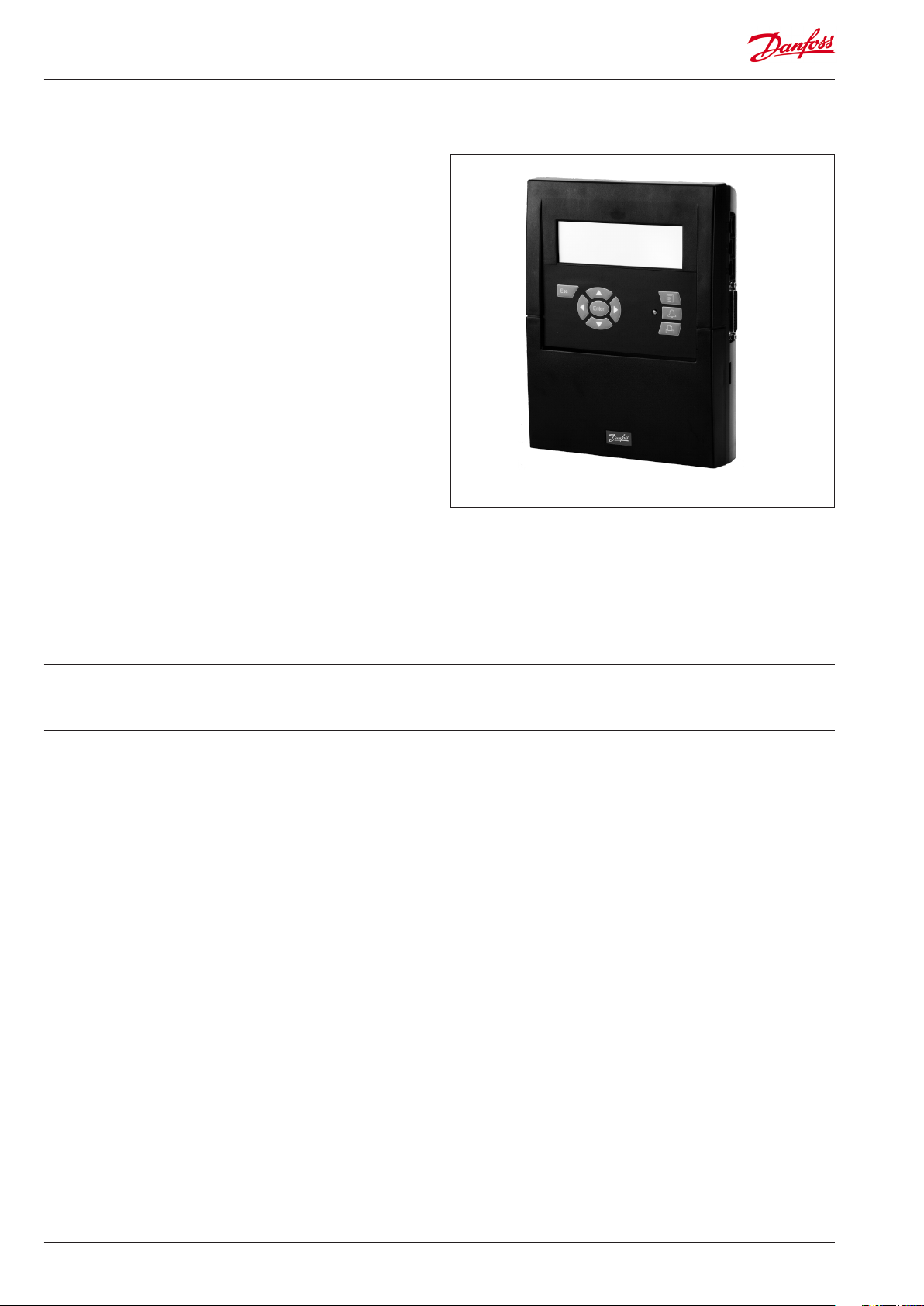
The AK-SM 350 is a combined data collection and monitoring unit
for use in refrigeration plant in small supermarkets.
It is used to record the temperature in the various refrigeration
applications, store this data and then present it as documentation
in compliance with regulatory requirements.
Along with recording temperatures, there are alarm limit settings
and the unit will emit an alarm if a threshold value is exceeded.
The alarm is presented on the display and it can be sent to an
external alarm destination such as a mobile phone or a service
company.
The unit is positioned centrally in the supermarket, and the userfriendly interface makes it easy to follow the dierent temperature
readings.
With just a few pushes of the buttons, graphs of the dierent
temperature sequences can be brought up, and in the event of an
alarm, the cause can be read from the display.
All store employees will be able to operate the monitoring unit
and authorised personnel will have access to important settings
with a password.
Setups and settings can be entered via the front panel, but if there
are a lot of names and settings, they can be entered using the AKST type software. This software must be loaded on to a PC.
If there is more than one AK-SM 350 that is to be programmed
with the same settings, the back-up and restore function in the
AK-ST software may prove useful.
Advantages
• Compact unit for registration of temperatures
• Collects temperature data to present to authorities
• System unit with
- Optimisation of suction pressure (P0 optimisation)
- Day/night override
- Alarm function
Contents
Overview .......................................................................... 3
Data .................................................................................. 6
AK-SM 350 ................................................................................................6
Installation ....................................................................... 8
Assembly ................................................................................................... 8
Connections .............................................................................................9
External communication ...................................................................12
Conguration ................................................................13
The functions' mode of operation ........................14
The display .............................................................................................14
The overview display ...................................................................14
Display screens for daily use .....................................................15
Main menu ......................................................................................15
Functions for daily use - Setups/adjustments ...........................16
Day / Night setup ..........................................................................16
Injection ON Signal ......................................................................17
Starting defrosts ............................................................................18
Adaptive defrost ............................................................................19
P0 optimization .............................................................................19
Adaptive Rail heat.........................................................................20
Conguration settings .......................................................................21
Basic setup ......................................................................................21
Setup of points ..............................................................................24
Alarm settings ................................................................................33
Alarm routes ...................................................................................34
Alarm destinations .......................................................................36
Print setup .......................................................................................40
IP conguration .............................................................................41
Relay conguration ......................................................................41
Setup for other networks via protocol interface ...............43
Alarm priorities ..............................................................................43
Daily use .........................................................................44
When there is an alarm ......................................................................44
When you want to print out a data collection ..........................45
When you want to see a graph of the collected temperatures
.............................................................................................................46
When you want to change the store's opening times ...........47
When you want to change the defrost times ............................48
Appendix - Template compiler ............................... 49
Menu survey ..................................................................53
2 Manual RS8EF602 © Danfoss 01-2016 AK-SM 350 Version 2.5x
Page 3
Overview
Number of connections
The AK-SM 350 is a central monitoring unit that can monitor up to
65 readings. They can originate from:
- up to 16 direct connections from sensors or switch functions
- signals from separate refrigeration controllers, EKC and AK types,
via data communication and AKC via interface AK-PI 200.
- signals from gas detectors. These readings are also transferred
via data communication.
Alarms
The unit advises you of an alarm in several ways:
• With an audio signal
• By ashing the LED on the front
• By showing an alarm symbol on the display
• In addition to this, the unit can route alarms to external alarm
destinations. This alarm routing can be categorised into priorities
and times for dierent alarm destinations at dierent times of
the day.
Alarms from freestanding refrigeration controllers received via
data communication are forwarded to the monitoring unit. The
warnings are then generated as described above.
Data collection
All dened points can be recorded and saved with the set time
intervals.
The values can be viewed on the display and retrieved by connecting a printer or connecting a PC or modem.
Signals
The following types of signals can be received:
• Temperature readings
• Switch functions
• Pulse signal for output reading
• Voltage signal
• Current signal
• Signals from refrigeration controllers types EKC and AK.
• Signals for P0 optimization
• Day/night override.
Gas detector
One or more of the measuring points can be a gas detector. The
gas detector is connected to the data communication, after which
it will send the measured value to the monitoring unit. If the
threshold value set in the monitoring unit is exceeded an alarm is
generated.
For further information on the gas detector, please see document
RD7HA or USCO.EN.S00.A.
Printer
The connection of a printer means that the data collected can be
printed out. The printer must be an HP PCL-3 compatible printer.
The print-out may contain:
• The measuring points’ actual values
• Graphic readout of temperature sequences
• Alarm history
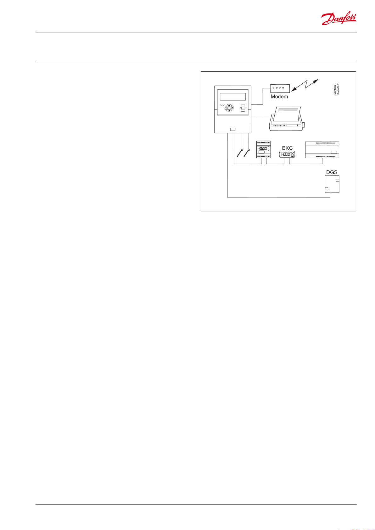
External connections
• Modem
A modem can be connected so that the unit can be in contact
with external alarm destinations or service companies.
The modem can be a standard telephone modem or a GSM
modem for mobile telephony.
• Ethernet
The link to external alarm destinations and service companies
can take place via a TCP/IP network.
• PC
A PC can be connected to the unit. The PC may be stationary,
portable or handheld. Setups and/or alarm receipt can be performed via an operating program.
• Service companies
Users of the following programs can receive alarm calls from the
unit.
AK series software (operating and setting)
AKM type software (only receiving alarms and logging data)
Security
Important settings are password-protected.
When logging on or out from external links, an additional security
check is required to verify the connection. This will be carried out
during the setup.
Battery Backup
The unit contains a battery, so that the clock function is still maintained if there is a power failure.
The recording of temperatures will resume when the power
comes back on.
All setups will be retained during a power failure.
AK-SM 350 Version 2.5x Manual RS8EF602 © Danfoss 01-2016 3
Page 4
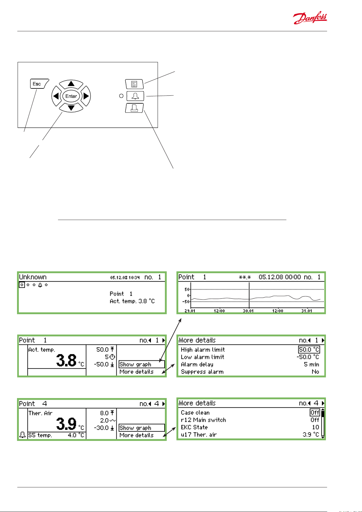
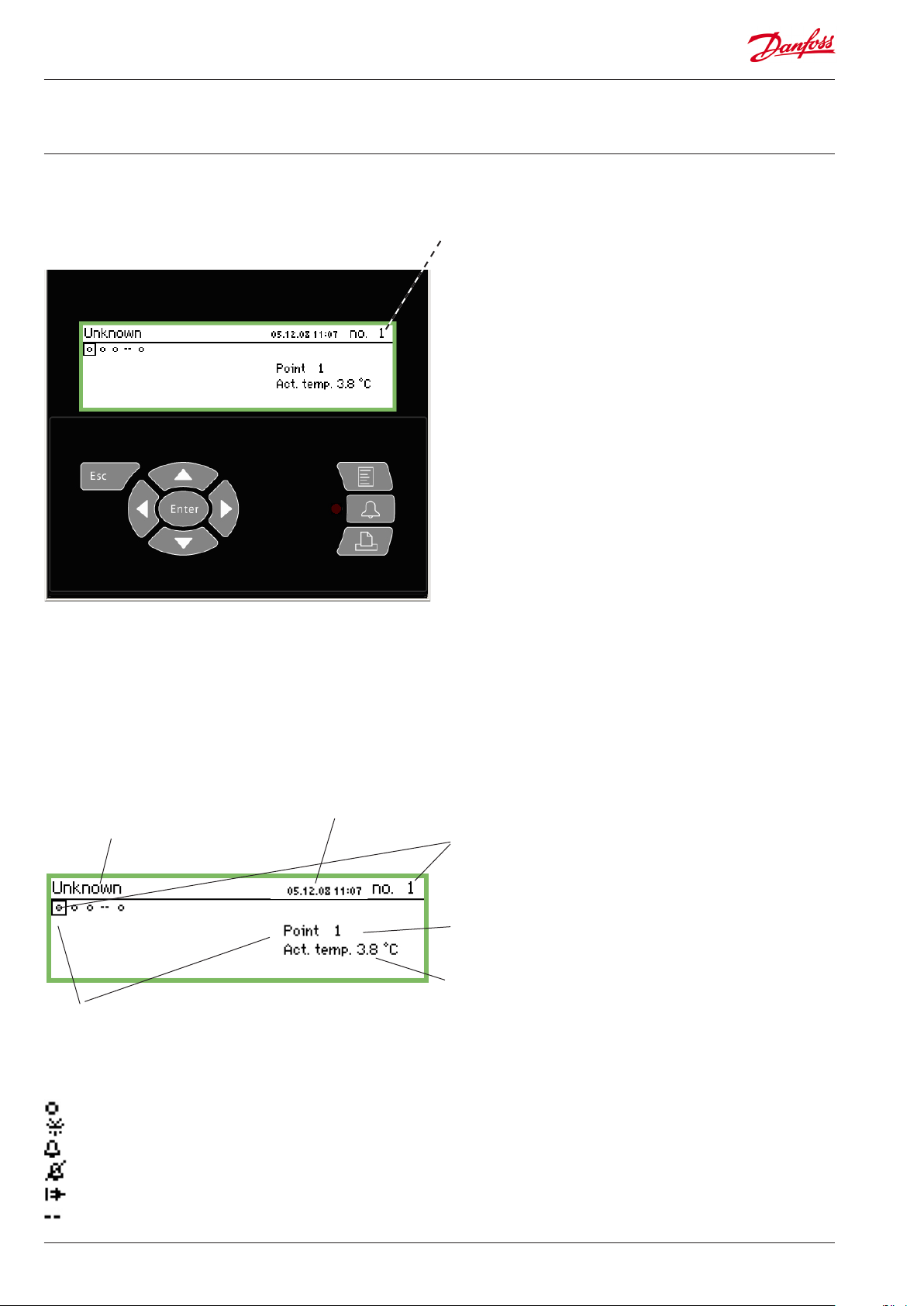
Operation
The following operation options are found on the front of the
monitoring unit:
Escape
• Goes back to the display readout
Navigation
• The arrow keys change what is highlighted in the display. Values
can be changed.
• "Enter" executes a selection.
When an "arrow" is shown on the top right-hand side of the
display, this means there are several menus for this level. Press an
arrow key to move to the menu.
Menu
Provides access to the menu system and consequently the setups.
See page 15 for more information.
Alarm signal and operating the alarms
• The LED ashes when there is a new alarm
• The LED lights up when the alarm is acknowledged and the
"error" has not been dealt with.
• The LED does not go out until the error has both been rectied
and acknowledged.
• The button shows the alarm text and stops the alarm signal
when it is pressed twice.
See overleaf for more information.
Print
• Starts the print-out function. Only used if a printer is connected
to the unit.
See page 40 for more information.
The display
There are several display screens used in daily operation. Here is a
short presentation:
• Overview display, with all measuring point
• Point detail display, showing the point’s actual values
• Point detail display from a controller
• Graph display, showing the point’s previous readings
• "More details" from a point
• "More details" from a controller
Descriptions of the display screens can be found on page 14
onwards.
4 Manual RS8EF602 © Danfoss 01-2016 AK-SM 350 Version 2.5x
Page 5
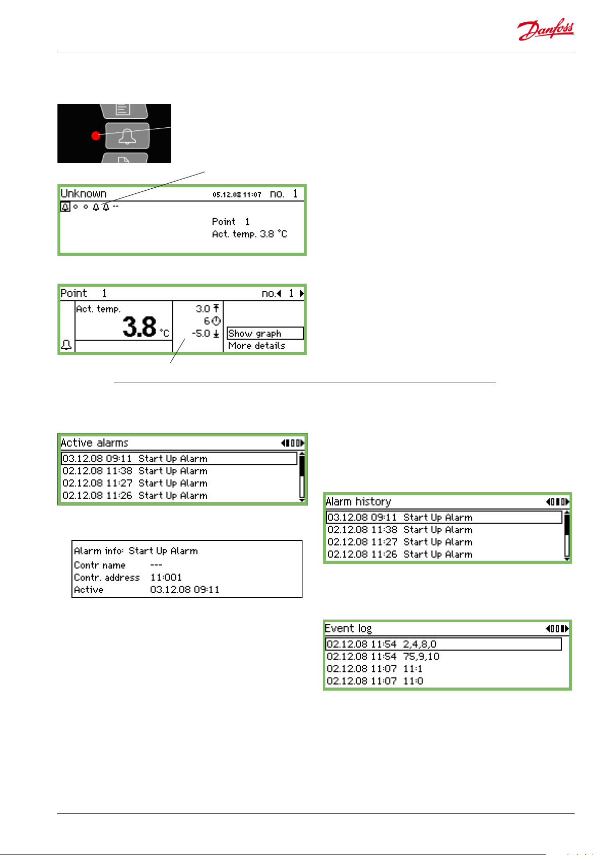
Alarm situations
If there is an alarm, the following will happen:
Flashes
Shows alarm symbol
This area shows the alarm limits and delay time
- An alarm symbol will appear in the overview display for the point
in question
- The LED by the alarm button will ash
- The built-in siren will be activated for a set period (but only if it
has been dened)
- If a relay to the alarm function has been dened, the relay will be
enabled
- When you move to the point in question, the alarm symbol will
also be visible at the bottom left-hand side
- The alarm text is entered into the alarm list of active alarms
- If external alarm destinations have been dened, the alarm and
alarm text will be forwarded to the destination.
If you press the alarm button:
- The alarm list is shown in the display
When you select an alarm from the alarm list of active alarms
and then press "Enter", you will see several pieces of information
about the alarm.
When you press the alarm button again:
- All the alarms are acknowledged (conrmation that they have
been seen)
- The built-in siren stops
- If a relay to the alarm function has been dened, it will return to
the state "no alarm" (relay conguration page 41).
- The LED by the alarm button stops ashing and changes over to
being lit constantly if the error is still there. It will go out if the
error has disappeared.
- The alarm text is transferred to the "Alarm history" list
- Active alarms will continue to be shown in the display.
(This second press (acknowledgement) can be blocked with a
password.)
When the alarm disappears:
- The alarm symbol in the overview display disappears
- A "cancelled alarm" is sent to alarm destinations (only IP, SMS
and modem connections).
If you want to see the Alarm history, you need to press the alarm
button and then the "right arrow" button
The Alarm history can store up to 200 alarms. Once it reaches 200 the
new alarms will overwrite the oldest ones.
If you want to see the Event log you need to press the alarm button
and then press the "right arrow" twice
AK-SM 350 Version 2.5x Manual RS8EF602 © Danfoss 01-2016 5
Page 6
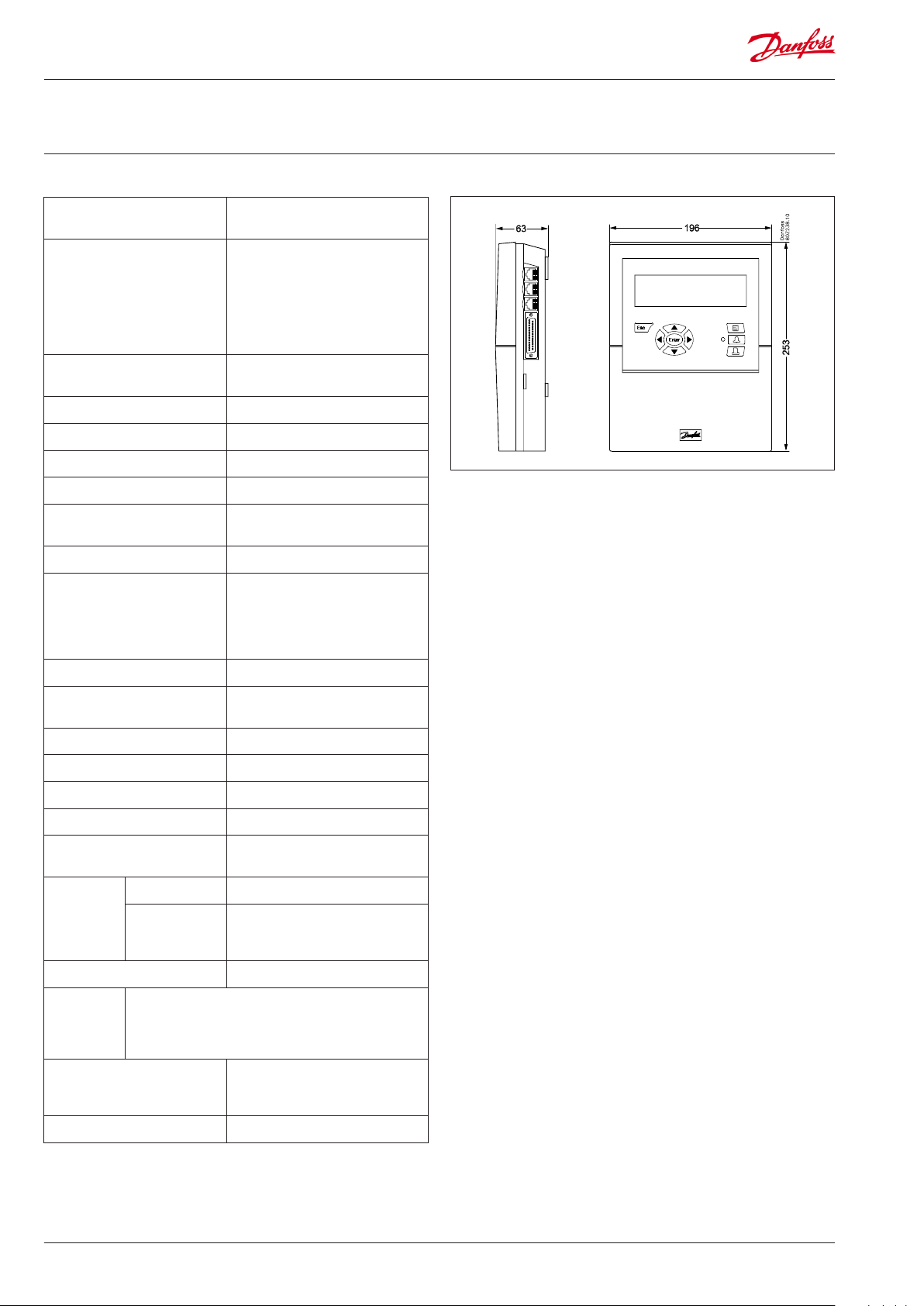
AK-SM 350
Supply 115 V / 230 V
+10/-15%, 50/60 Hz, 10 VA
Data
Connection PT 1000 ohm at 0°C or
Pulse counter inputs for output
reading
Display Graphic LCD, 240 x 64
Direct measuring points 16
Total number of points 65
Measuring range, general -100 to +150°C
Measuring accuracy at Pt 1000 Resolution 0.1 K
Measuring interval 15, 30, 60, 120 or 240 minutes
Data capacity 12 MB ash
Battery backup Button cell for clock function (2032)
Power supply for e.g. pressure
transmitter
PTC 1000 ohm at 25°C or
NTC 5000 ohm at 25°C or
Termistor (-80 to 0, -40 to 40 or 0
to 100°C)
Digital On/O signal or
Standard 0 - 10 V / 4 - 20 mA signal
Acc. to DIN 43864.
(Only for inputs 1 and 2)
Accuracy: +/- 0.5 K
Recording of all data from all
measuring points for one year at
30-minute intervals.
Last 200 alarm warnings
5 V max. 50 mA
12 V max. 50 mA
Printer connection HP PCL-3, Parallel
Modem connection RJ 45
TCP/IP connection RJ 45
PC connection RJ 45 (RS 323)
Data communication RS232, RS485 (LON), RS485 (MOD-
Relays Quantity 2
Max. load 24 V a.c. or 230 V a.c.
Enclosure IP 20
Ambient
environment
Approvals EN 60730-1 and EN 60730-2-9
Weight 1.6 Kg
Capacitive load
The relays cannot be used for the direct connection of capacitive loads such as LEDs
and on/o control of EC motors.
All loads with a switch mode power supply must be connected with a suitable contactor or similar.
0 to 50°C, during operation
-20 to +70°C, during transport
20-80% RH, Non-condensed
No shock loads/vibrations
bus), RS485 (TP) (TP= Third Party)
Imax (AC-1) = 5 A
Imax (AC-15) = 3 A
EN 61000-6-3 and EN 61000-6-2
EN 12830 and EN 13485
6 Manual RS8EF602 © Danfoss 01-2016 AK-SM 350 Version 2.5x
Page 7

Ordering
Type Measuring points Description Language Code no.
English, German, French,
Dutch, Italian
AK-SM 350 16
Cable for PC
(see also AK-ST 500 literature)
Modem cable 080Z0261
With inputs for PT 1000 ohm,
PTC 1000 ohm , NTC 5000 ohm
RJ 45 - Com port 080Z0262
English (UK), Spanish,
Portuguese, English (US)
English, Polish, Czech 080Z8504
080Z8500
080Z8502
AK-SM 350 Version 2.5x Manual RS8EF602 © Danfoss 01-2016 7
Page 8
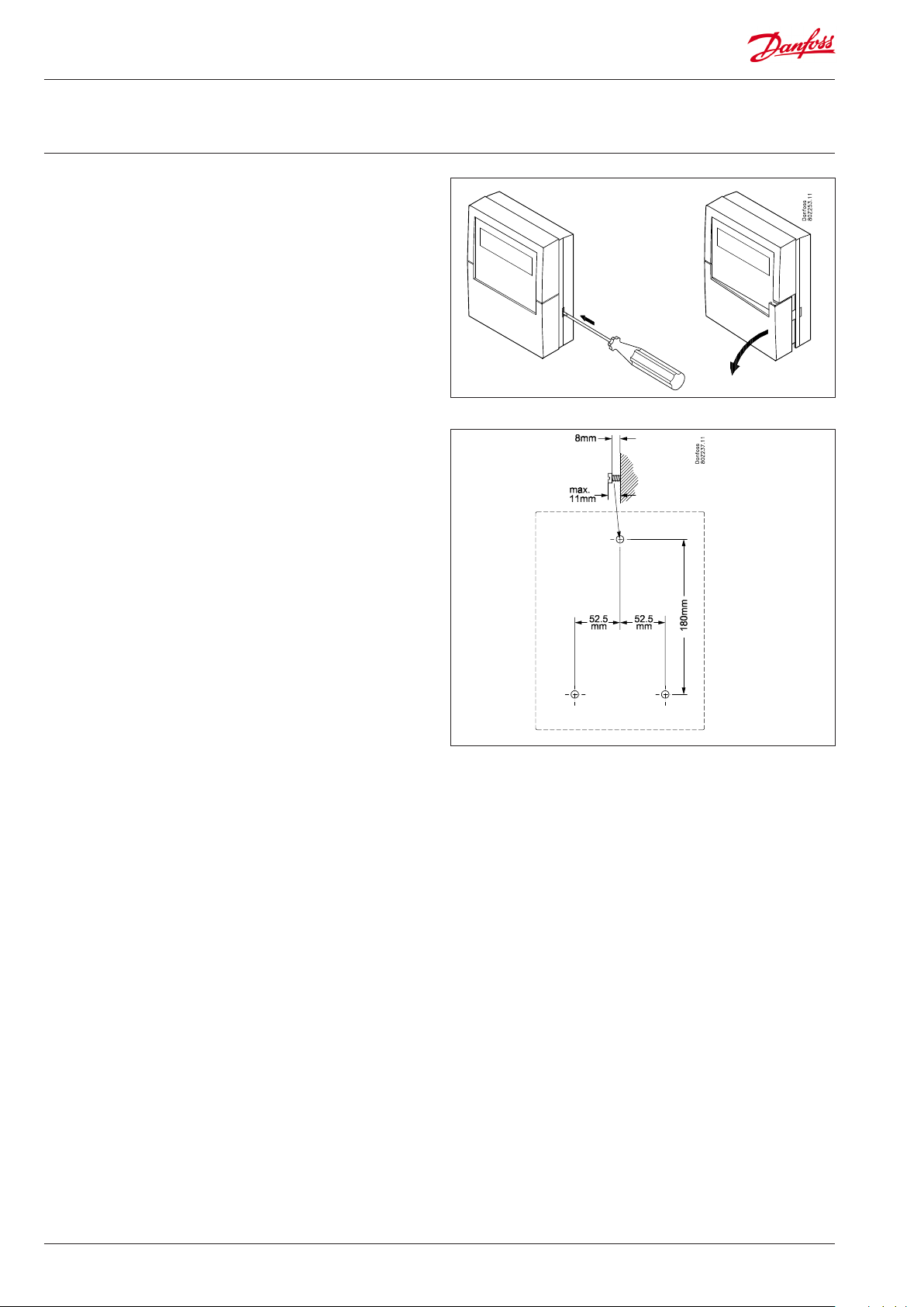
Installation
Assembly
Opening
1. Release one of the two snap catches on the side of the unit.
2. Pull o the cover.
Closing
Push the cover into place so that the two snap catches click shut.
Position
The unit should be positioned as follows:
• At eye level
• Not in direct sunlight
• Nowhere strong light can cause reections on the display
• Not in extreme temperatures or anywhere damp
• Not close to sources of electrical interference
The unit is secured with 3 screws.
The top one is positioned at eye level. Make sure that the head of
the screw is not sticking out so much that it is touching the PCB.
Then hook the unit on the screw and t the two remaining screws.
8 Manual RS8EF602 © Danfoss 01-2016 AK-SM 350 Version 2.5x
Page 9
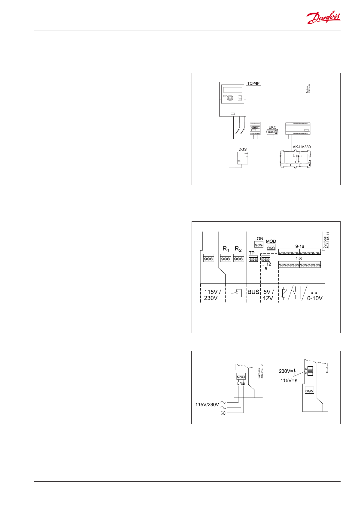
Connections
Principle
Up to 16 direct readings can be connected to the AK-SM 350.
If the number of direct measuring points is not sucient, readings
can be retrieved from an AK-LM 330. The readings are retrieved via
the RS485 - LON data communication.
Readings from a gas detector are also retrieved from this data
communication.
If separate refrigeration controllers (type EKC or AK) are used,
temperature readings can be retrieved from these controllers.
The readings are retrieved via the RS485 - LON or MOD-bus data
communication.
Controllers type AKC (DANBUSS data communication) can be connected via AK-PI 200 connected to the TCP/IP input.
Connections overview
The supply voltage is connected on the left-hand side. Next to this
connection are two relays which can, for example, be used for the
modem reset, watchdog or alarm relay. For safety reasons both
relays must be used at the same voltage – 24 V on one relay and
230 V on the other is not permitted.
On the right-hand side all the connections are low voltage.
There are three types of data communication which can be connected to other Danfoss cooling controllers equipped for the
same type of data communication.
Then there is a 5 V and a 12 V supply. They can be used for supply
voltage to a pressure transmitter that is to provide a signal to one
of the measuring points.
There are 16 connections on the far right-hand side. They can be
linked up however you like to signals from sensors, switch functions and voltage signals of up to 10 V. However, if there are pulse
readings, they must be linked up to nos. 1 or 2.
1. Supply voltage
The supply voltage must be 230 V AC or 115 V AC. At
connection, the changeover switch must be set to the actual
voltage.
The permitted tolerances mean that the supply of 115 V also
includes supply voltages of 110 V and 120 V.
1. 2. 4. 3.
AK-SM 350 Version 2.5x Manual RS8EF602 © Danfoss 01-2016 9
Page 10
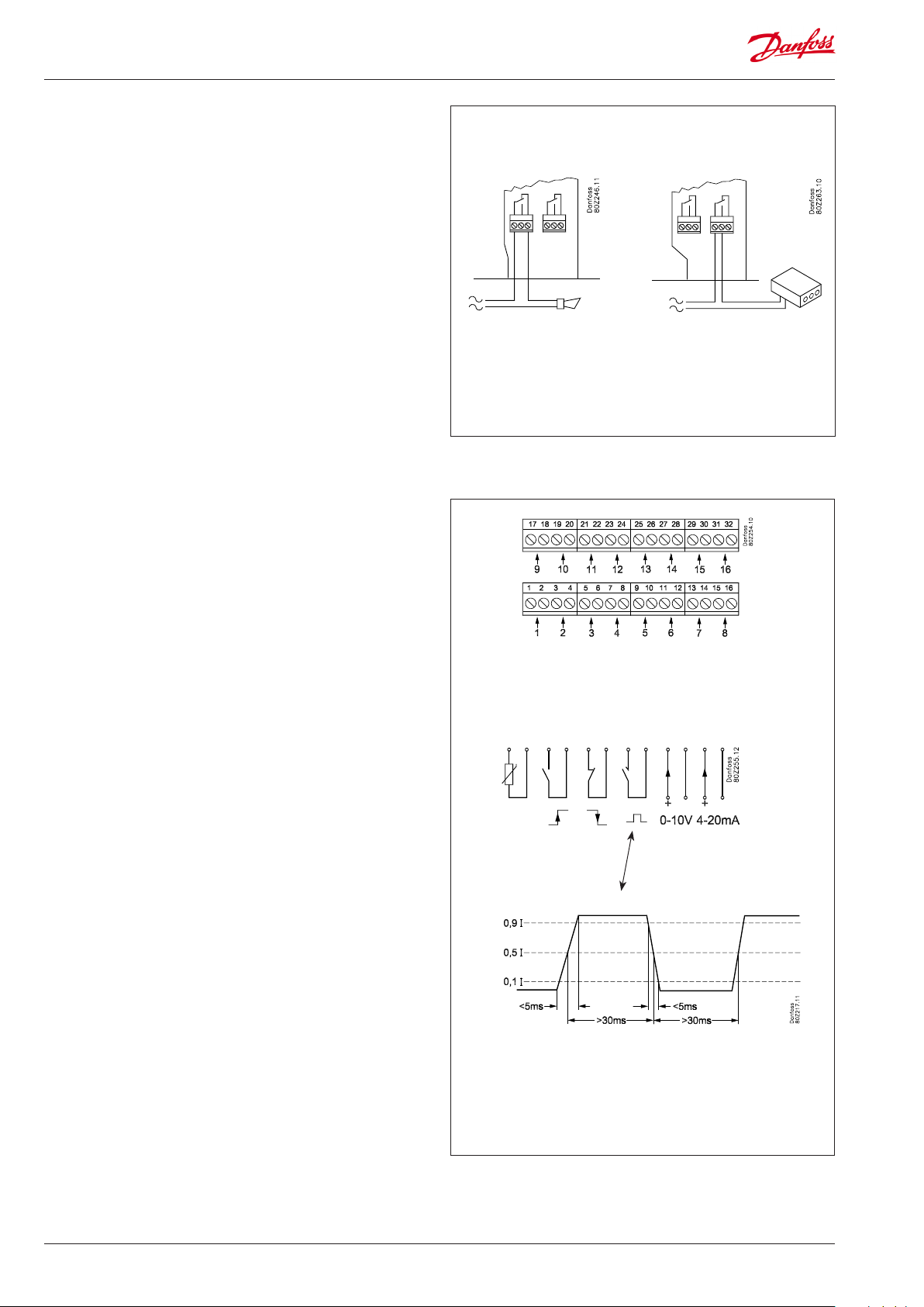
2. Relays
The two relays can be used for:
• External alarm function
When connected as shown, an alarm will be emitted in alarm
situations and when the power to the AK-SM 350 disappears.
• Resetting the supply voltage for a modem
After a power outage, the AK-SM 350 will control the supply
voltage for the modem, ensuring the modem restarts in a
controlled manner.
• Watchdog
Here the relay is enabled in time intervals. For example, once
an hour. If there is no relay change, an external unit will sound
an alarm.
The two relays must be connected to either low or high voltage
(115/230 V), but not low voltage on one and high voltage (115/230
V) on the other.
3. Direct measuring points
There are 16 direct measuring points.
All the odd numbers are signal inputs. All the even numbers
are earth. All the even numbers on the PCB behind the terminal
block are linked to a common earth.
If you use a common earth wire to several measuring points you
should delimit it into groups. Do not put temperature signals,
switch signals and voltage signals in the same group.
Keep your distance from sources of electrical interference and
power lines.
Relay 1
Relay 2
Sensor connections
One of the conductors is wired to an odd terminal block
number. The other is wired to earth (even number).
On/o signals from a switch function
One of the conductors is wired to an odd terminal block
number. The other is linked to earth (even number).
The switch can either be a make contact or a circuit breaker. The
function is dened under setup.
Output reading (pulse recording)
Only measuring points 1 and 2 can be used for output readings.
These inputs are designed for fast on/o changes.
Pulses are measured in accordance with DIN 43864.
The signal is wired as an on/o signal.
Voltage signal
The voltage can vary between 0 and 10 V DC.
Minus is wired to earth (even number).
Current signal
The current signal can vary between 4 and 20 mA.
Minus is wired to earth (even number).
Gas detector, type DGS
This gas detector can give a voltage signal or a current signal for
AK-SM 350.
DIN 43864
S01 interface
10 Manual RS8EF602 © Danfoss 01-2016 AK-SM 350 Version 2.5x
Page 11
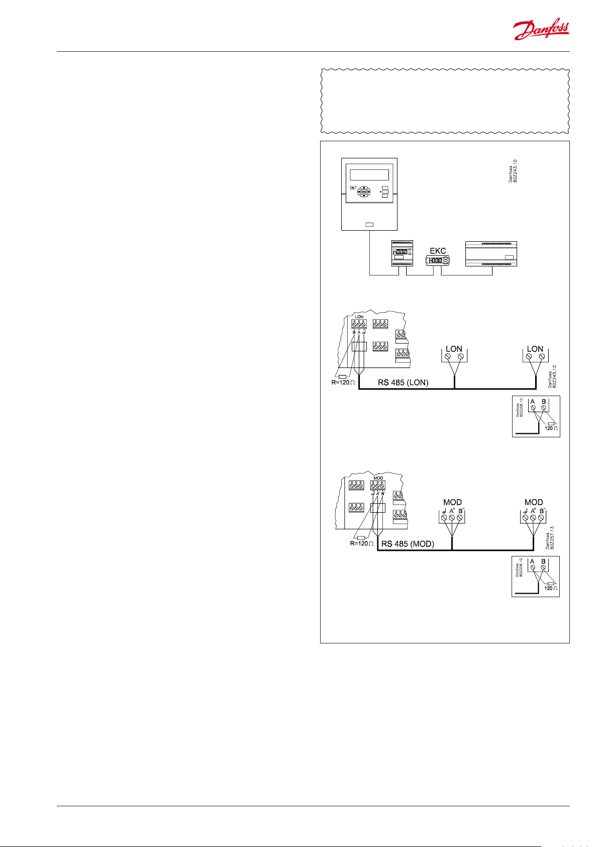
4. Data communication
If readings are to be retrieved via data communication, this
must be done as follows:
Controllers
The AK-SM 350 can receive signals from a number of controllers.
The controllers are connected to the RS485-LON communication
or RS485-MOD-bus communication. These two types cannot be
mixed.
Cable
There are no requirements concerning the positioning of the
AK-SM 350 for data communication. It can be at one end of the
cable or it can be anywhere along the cable.
Wiring
• LON-bus
There are no requirements concerning the polarisation of the
A and B connections. The screen connection must be looped
onwards for each controller.
• MOD-bus
A+ must be wired to A+.
B- must be wired to B-.
The screen connection must be fed onwards and tted into all
controllers.
Termination
Each end of the data communication cable must be terminated
with a resistance of 120 Ω. In some EKC controllers a termination jumper is tted. Termination takes place here by closing the
jumper.
The actual installation of the data communication cable must
comply with the requirements mentioned in the document
"Data communication between ADAP-KOOL® Refrigeration
controls". Literature sheet number = RC8AC.
Addressing
Every controller must have an address set. This address will then
be recognised by the AK-SM 350.
BUT this is provided that the address has not already been dened
for the other side (another controller on the same or dierent data
communication). If it has already been used, the existing setting
will be kept and the last one entered will not be used. Nor should
you use an address taken by a gas detector. Duplicated addresses
are not permitted.
• Each EKC controller must have "o03" entered with every address.
• The AK-SM 350 is then able to receive these addresses. There
are two possible ways for this to happen:
- Either by activating "o04" in every EKC controller, but this will
require a voltage on the AK-SM 350. (Controllers with MODbus communication do not have an "o04".)
- Or by enabling the "scan function" in the AK-SM 350. This
requires all the EKC controllers to have an address set. A
controller with MOD-bus communication can only be found
via this scan function.
In the later setup, we want to activate the "scan function", after
which all addresses can be viewed in the network list.
Gas detector, type GD
If a type GD gas detector is used, it must be connected to the
"TP" data communication.
For assembly and connection, please see literature sheet
RD7HA.
Set the address in the gas detector (max. no. of addresses is 65).
An address used by an EKC controller must not be duplicated.
Make a note of the address. It will be used later on, when the
AK-SM 350 has to be set up.
AK-SM 350 Version 2.5x Manual RS8EF602 © Danfoss 01-2016 11
Page 12
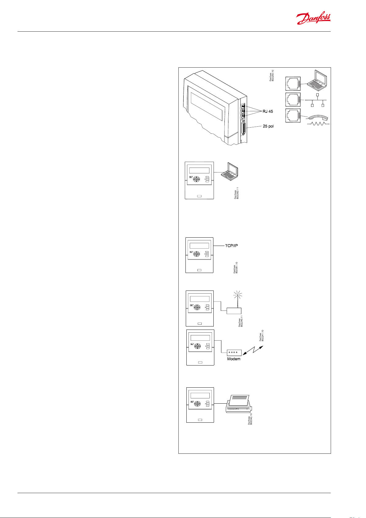
External communication
Danfoss
80Z260.11
At the side of the unit there are connectors for external communication.
They can be used for the following:
• Setting up the unit
• Receiving alarms at a service company
• Receiving alarms on a mobile phone
• Service
• Printer connection. Printing out logs and alarms
PC connection
This connection can be used when setting up the unit or when
carrying out service.
The PC must have the AK service tool program uploaded.
If text for individual points needs to be entered, it would be a
good idea to use a PC connection.
If several units are to be installed with the same setup, it would be
very helpful to use the copy function in the AK service tool.
If logs are to be retrieved from the unit, this can also be done in
this way.
See also the literature sheet for the AK service tool.
TCP/IP connection
Here the unit can be linked to an Ethernet or a unit can be connected for setup and service.
Fx AK-PI 200 and controllers with DANBUSS data
communication
Modem connection
Here a modem can be connected to a xed network or mobile
network.
Printer connection
The printer can be connected when there is a need for print-outs
of e.g. logs, alarms or curves of a temperature sequence.
GSM / SMS
Cable = Modem cable
GSM Box: Siemens TC35I
(Danfoss' approved suppliers list)
Fixed network
Cable = Modem cable
Modem: Ask for a copy of
Danfoss' approved suppliers list.
Cable = Standard parallel
Printer: HP PCL-3 compatible.
Ask for a copy of Danfoss' approved suppliers list.
12 Manual RS8EF602 © Danfoss 01-2016 AK-SM 350 Version 2.5x
Page 13
Conguration
Principle
This page describes the setups that are to be installed in the
monitoring unit.
The points are detailed briey so that the list can be used as a
checklist.
The monitoring unit is set up once each point has been reviewed.
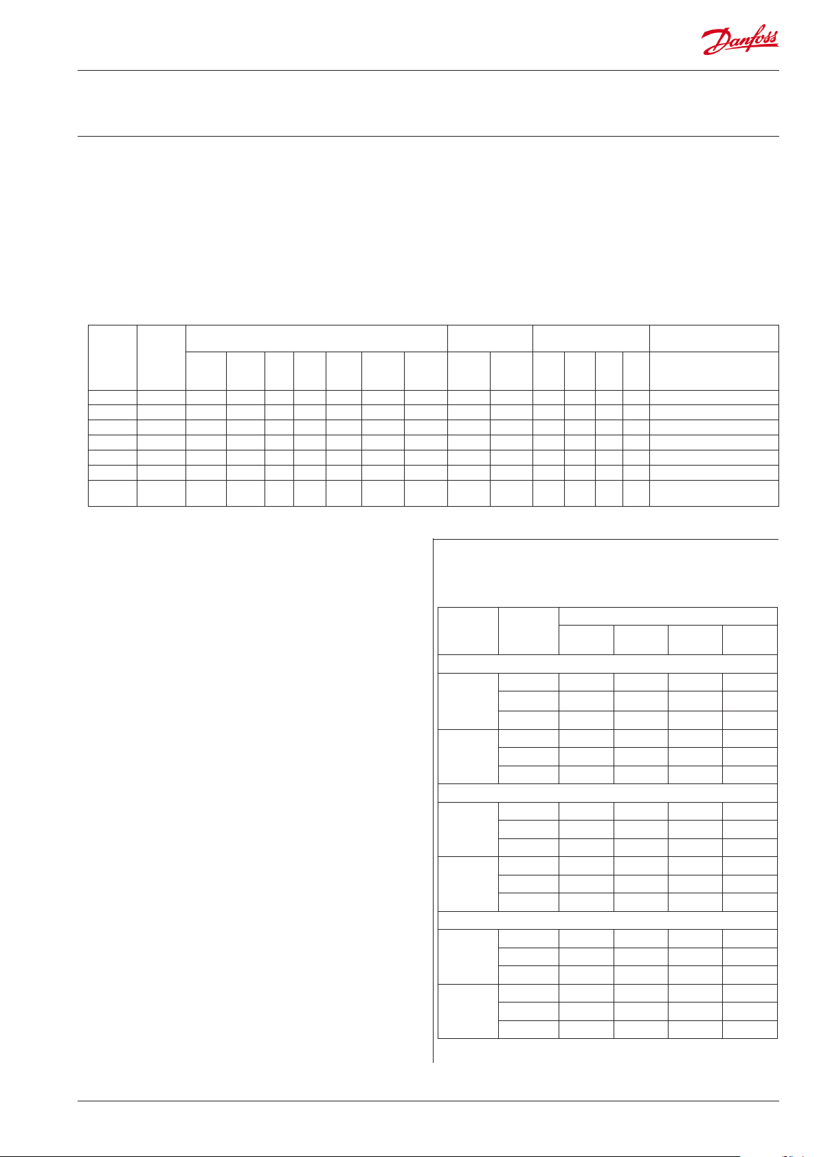
Procedure
1. Create an overview of all the connections.
Decide where they will be connected.
Decide the alarm priority for the reading.
The table below shows some examples of the various possibilities.
Point no.
in display
Name Type of connection Place of
Tempe-
Di
Ai
Pow-
Power
rature
(on/
(analog)
er
meter
o)
1 xxxx A x 1-16 x
2 xxxx B x 1-16 x
3 xxxx C x 1-16 x
4 xxxx D x 1-2 x 1 or 2 only
5 xxxx E x 1-65 x
6 xxxx F x 1-xxx x
7 xxxx G x Load/store data from Power
meter
log
Gasdetector
If you require help setting up individual points, you will nd a
more detailed explanation in the next section – The functions’
mode of operation.
connection
Controller Terminal Address High Me-
Priority of alarm Note
Low Log
dium
only
meter
Then continue by:
2. Pressing the button for the main menu
3. Selecting "Service Setup" at the bottom of the display
4. Go through all the functions in "Basic setup". In one of the functions, the network will be scanned, which allows the monitoring
unit to recognise all the connected units on the data communication. Do not forget that the controllers must have an address
set, or to check that the power is turned on before the scan
function is enabled.
5. Select Point setup
6. Set all points. Use data from a table like the one above. Some of
the readings will have two alarm limits. Dierent alarm priorities
can be set for each one.
7. Create a table of the alarm activities. See the table on the right.
8. Set up the alarm function
a. Set the general functions rst
b. Then set how an alarm should be handled/routed (i.e. what
will be enabled)
c. And nally, set up the activities chosen (e.g. addresses of the
alarm destinations)
9. Check that the alarms can be sent properly
a. Set the function "Test alarm priority" to "high"
b. Enable the function "Test alarm"
c. Check that the alarm is received
d. Repeat this check for the other alarm priorities
e. Repeat this check until all the destinations have been tested
to see if they can receive alarms.
Table of alarm activities (example)
(Referred to in point 7 and utilised in point 8b)
Route 1
Time Alarm
Day High 1 x
Night High 2
Day High
Night High
Day High
Night High
priority
Medium 1
Low 1
Medium 2
Low -
Alternate destination (if the link to the primary destination fails)
Medium
Low
Medium
Low
Medium
Low
Medium
Low
Remote
no.
Primary alarm destination
Copy destination
Alarm activity
Relay Buzzer SMS
AK-SM 350 Version 2.5x Manual RS8EF602 © Danfoss 01-2016 13
Page 14
The functions' mode of operation
The display
This section will explain all the dierent functions in the dierent
display screens.
In the overview display you can use the buttons to get to the
dierent points, or the monitoring unit can be set up to "scroll"
through the points. The view is reset once the last point has been
shown.
When an arrow is shown in this position, you can move to the next
or previous point (or display) by pressing the "right arrow" or "left
arrow".
This is the overview display that shows all the dened readings.
Here each point is represented by a symbol.
Point 1 is at the top left. 2 comes next and so on. A total of 65
points, and thus 65 readings, can be shown.
A reading can be a :
• Temperature reading
• Voltage signal or current signal
• On/o signal from e.g. a door switch
• Pulse signal from an output reading
• Signal indicating that a defrost cycle is in progress
• Signal from a gas detector
• Signal from a refrigeration controller. In this case the reading
could be a temperature etc.
If you want to see the reading for point 3 for example, you need
to press the "right arrow" or "left arrow" a number of times until
point 3 is highlighted. Then you need to press "Enter" in order to
see the next display.
Changing the light strength
Hold the ESC button down and press the up/down arrow.
The overview display
The readout always returns to the overview display if it is inactive
for two minutes.
Name
The name of the plant will be entered here.
Symbol for each point
When a point is marked with a square, the text and reading for this
point will be shown at the right of the display.
A symbol for the point is shown inside the square.
The symbol could be one of the following:
Circle = Point
Drops = Defrost
Alarm
The alarm has been suppressed (via the "More details" screen)
Connector = No link to controller
Dashes = Conguration error. See page 26 for information.
Date and time
Changing the contrast
Hold the ESC button down and press the left/right arrow.
Point number
Here it is no. 1 of the 5 dened points.
This text will be replaced with a text that tells you more about the
point, e.g. "Fruit and vegetables".
Reading
Scanning of all points
This function can be chosen as an option. The point's value is
shown here for about 3 seconds. Then it moves on to the next
point. When all the points have been scanned, the process starts
again from the beginning.
14 Manual RS8EF602 © Danfoss 01-2016 AK-SM 350 Version 2.5x
Page 15
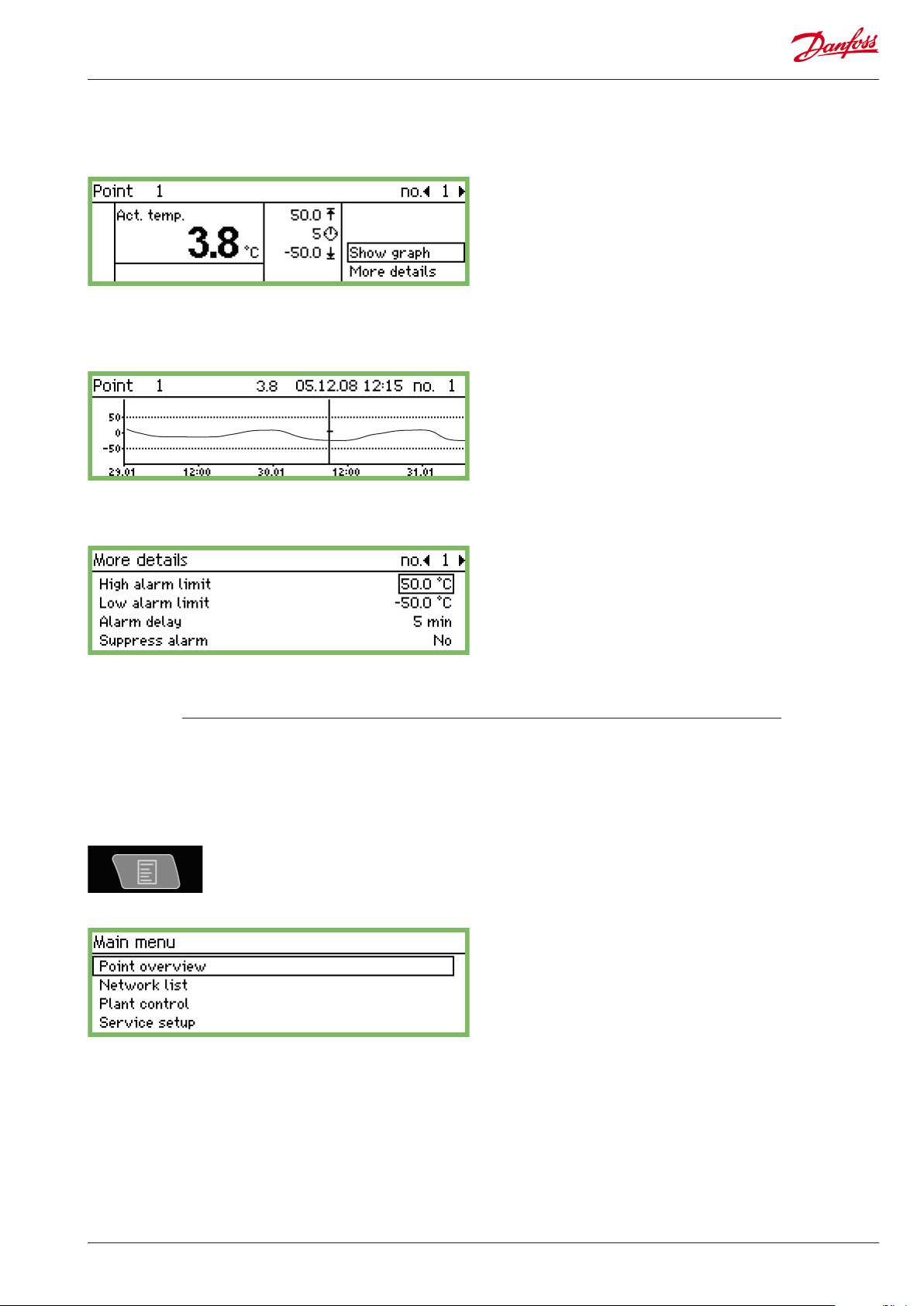
Display screens for daily use
• Point detail display, showing the point’s actual values
• Graph display, showing the point’s previous readings
Name and point number
• Symbol illustrating the operating situation of the point
• Temperature values
• Value for the high temperature alarm
• The delay time for the alarm
• Value for the low temperature alarm
• Access to the graph screen etc.
Temperature sequence for the point
If you want to examine the values from the graph more closely,
press "Enter". A vertical line will then be shown on the graph. This
line indicates the time of the graph.
The temperature value for this time is shown on the top line.
The vertical line can be moved using the arrow keys.
If you want to zoom in or out on a time, use the up/down arrow
keys. These are indicated on the top line with an up arrow and
down arrow.
The values in the "More details" screen can be changed from the
monitoring unit. The new setting will be sent to the controller.
The values in "More details" are written to the controller if they are
changed.
Main menu
The main menu comes up if you press the top right-hand button
on the front panel.
You can access the following four functions from this menu:
Point overview
From here you can go back to the overview display. Please see the
previous page.
(The monitoring unit will automatically return to the overview
display if the buttons are not activated for 2 minutes.)
Network list
The units that are connected via data communication are shown
here.
The readout is only available during setup and service (e.g. in an
alarm situation in which no signal is received from a controller).
Plant control
Here you will nd the functions that are used in daily operation,
i.e.
• Defrost and lighting schedules
• Defrost setups
• P0-optimization
This screen is described overleaf.
Service setup
This is where the basic setups for the individual points and functions are carried out.
This screen is described from page 21 onwards.
AK-SM 350 Version 2.5x Manual RS8EF602 © Danfoss 01-2016 15
Page 16
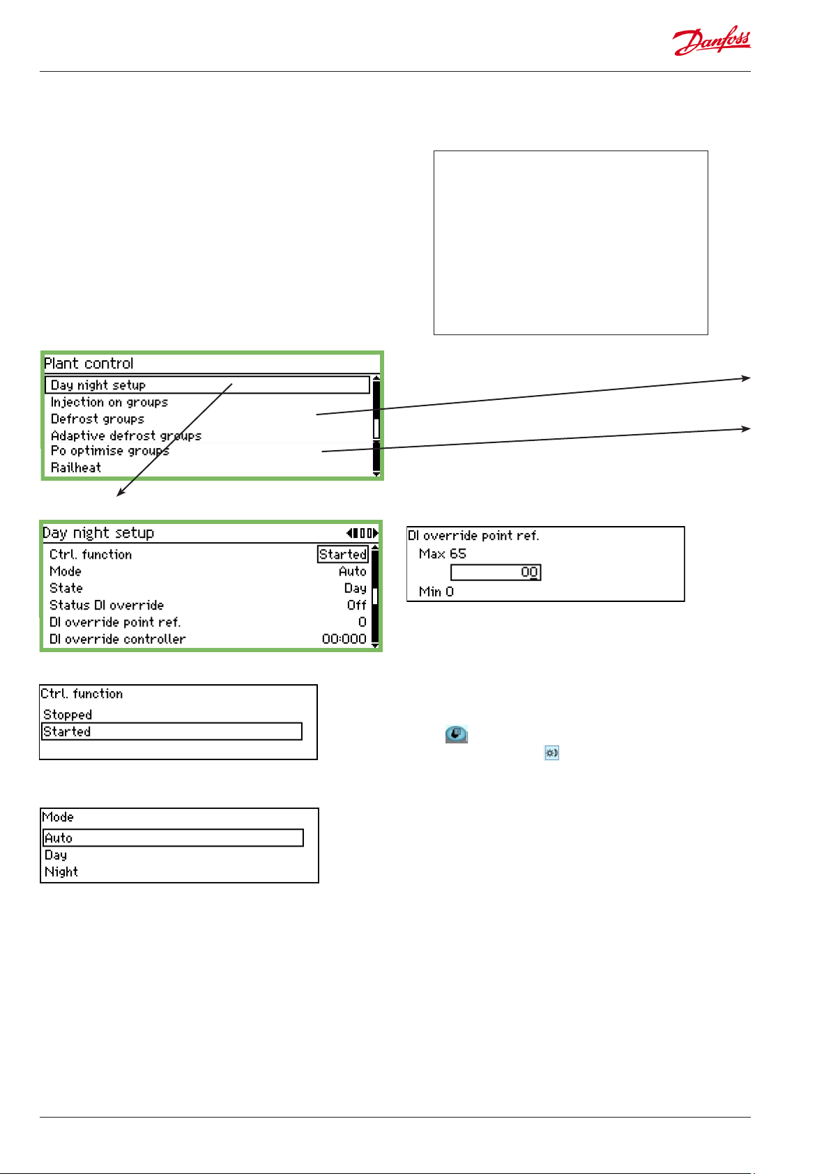
Functions for daily use – Setups/adjustments
This is where you set the functions used for daily operation.
• Time schedule for specifying the store’s opening time
This schedule is for sending a signal to selected controllers in
order to tell them that the temperature needs to be adjusted
because covers have been placed over the refrigeration applications.
The schedule is also used to route alarms. However, this is only
if dierent alarm destinations have been dened for the day
period and the night period.
• Time schedule for specifying defrost points
The schedule is used to send signals to selected controllers telling them to start a defrost cycle.
To the end user
These functions are an option, but they are only applicable if controllers have been installed that can
receive the signals in question.
To the installer
Please put a cross in the box if the functions have
been installed in such a way that they can be operated from the monitoring unit.
Yes
No
Defrosts, see 2 pages further
P0 optimisation, see 3 pages further
Day / night setup
Control:
If "Started" the signal status will be sent to the EKCs.
Mode:
• If "Auto" is selected, day and night will change automatically.
The signal follows the on/o value on the reference point. See
next setting.
• If "Day" is selected, the controller will always be in daytime
operation.
• If "Night" is selected, the controller will always be in night-time
operation.
DI override from a Reference point (see “Mode” = auto)
The point which the override signal is to follow is selected here.
If the point is On, the signal status “Day” will be sent to the EKCs.
DI override from a controller parameter
The address and parameter can be set via service tool type AK-ST
500. This is performed as follows:
1. Connect the AK-ST 500 to the monitoring unit
2. When the network overview is shown, press the plant control
button
3. Select day/night group
4. Select the location from which the signal will come:
a. Press 'New'
b. Select controller address (e.g. 001:005)
c. Select the group from which the signal will come
d. Select which parameter will send the signal
State:
This display shows whether the controller is in Day or Night mode.
Status DI override:
This display shows the status of the override signal, which is received from one of the two following settings.
16 Manual RS8EF602 © Danfoss 01-2016 AK-SM 350 Version 2.5x
Page 17
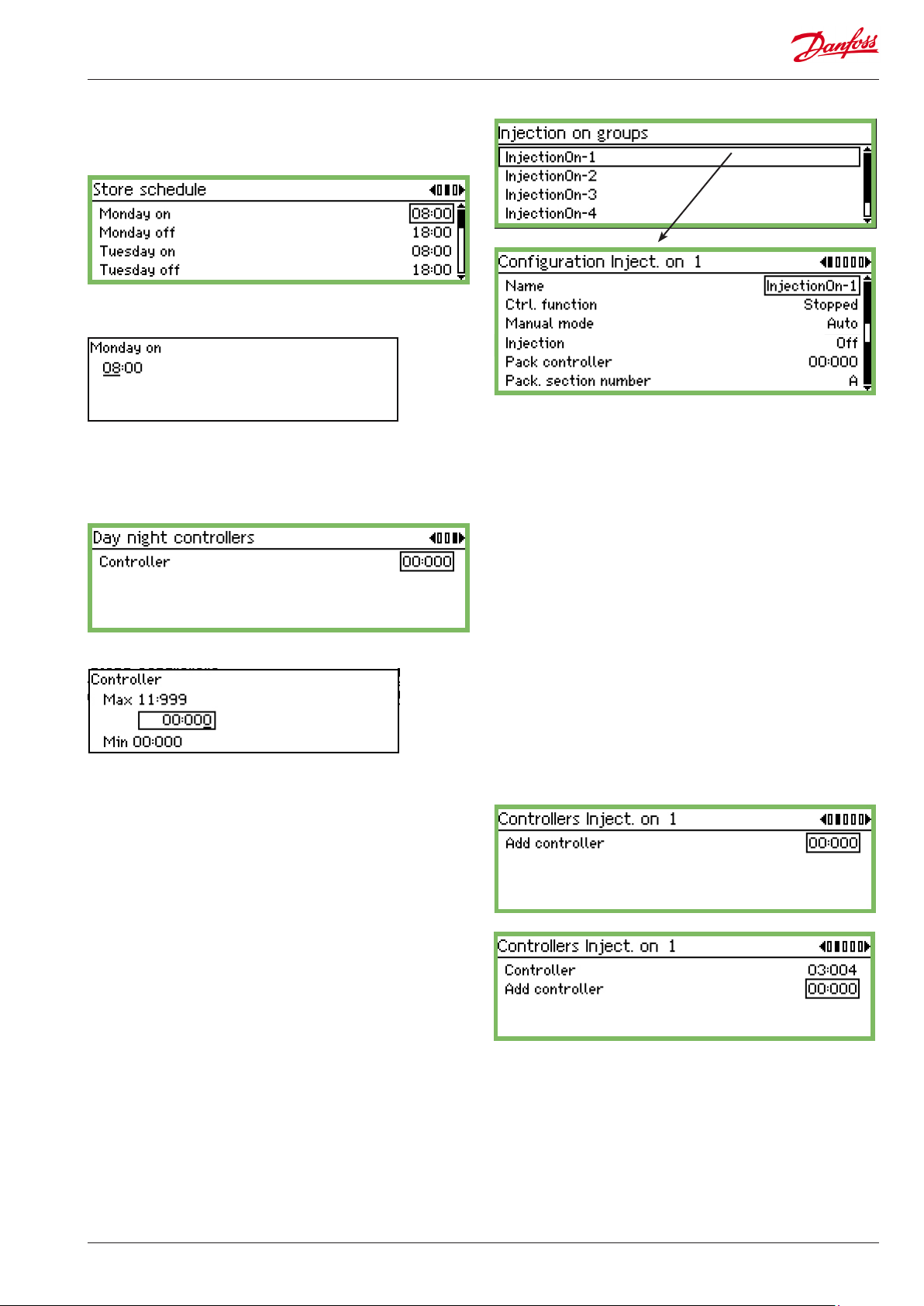
Time schedule
(The schedule is found "one arrow to the right" of "Day/night
setup")
This is where you set the store’s opening and closing times. The
times can be used for alarm routing and day/night signals to the
controllers.
The hour setting and minute setting is entered using the arrow
keys.
Day/night signal controllers
(The schedule is found "one arrow to the right" of "Store schedule")
Inject ON signal
Name
Enter the name of the group here.
Ctrl. function
Here the user can see if the compressor regulation is in operation
or stopped.
Manual
Here the Injection On regulation can be overridden
This is where you set the addresses for all the controllers that are
to receive day/night signals
Set address.
(00:000 means no address).
Injection
Here the status of the Injection On function is shown
Pack controller
The address of the controller regulating the compressors is set
here.
Pack section number
If the controller can control more than one compressor group, the
current group must be set.
Press 'right arrow' to dene the controllers that will receive the
signal.
Set the controller's address and press 'Enter'.
Continue with the addresses of the other controllers.
AK-SM 350 Version 2.5x Manual RS8EF602 © Danfoss 01-2016 17
Page 18

Starting defrosts
This is where you select a group of controllers which are to have a
defrost signal.
There are two ways in which the controllers can be grouped:
1. Individually. Once the defrost has started, each controller will
carry out the defrost and then restart refrigeration as soon as
possible afterwards.
2. Coordinated. In this case, refrigeration will not resume until the
whole group has nished defrosting.
It is possible to create 10 defrost groups, with each group containing a max. of 30 controllers.
The way to access the groups is shown on the previous page.
Group 1
Defrost schedule
(You will nd the setting "one arrow to the right" of the group.)
Up to 8 defrosts per day can be started.
A defrost time point is dened by setting a time. The time point
00.00 will not start a defrost.
Controllers group
This is where you dene which controllers are to be in the group.
(You will nd the setting "one arrow to the right" of the schedule.)
Name
Enter the name of the group here.
Defrost function
By using the setting “Started” the function is active. The schedule
determines when the signal is to be sent to the individual controllers.
Starting a defrost manually
By pressing “Enter” you start a defrost in all the controllers in the
group.
Coordination
(There can be up to 30 controllers in a group.)
Controller address
State the address of the controller that is to be part of the group.
Once the address has been set, you will automatically be able to
enter one more.
Group 2.
If there is a second or third group, or more, settings must also be
entered for these.
Select "Yes" if the whole group can only start cooling once the last
controller has completed a defrost cycle.
(The group of controllers must support the function.)
18 Manual RS8EF602 © Danfoss 01-2016 AK-SM 350 Version 2.5x
Page 19

Adaptiv Defrost
Other defrost groups can be created in which the controllers have
an adaptive defrost function. The controllers receive signals for the
current condensing temperature from the condensation control.
Only controllers with the adaptive function can be selected for the
group.
Name
Enter the name of the group here.
Ctrl. function
This display shows whether the defrosting is in operation or has
been stopped.
Group 1
Name
Enter the name of the group here.
Starting and stopping the function
Actual P0
The condensing temperature received from the compressor
control can be read here.
Pack controller
The address of the controller regulating the compressors is set
here.
Pack section number
If the controller can control more than one compressor group, the
current group must be set.
Press 'right arrow' to dene the controllers that will receive the
signal.
Set the controller's address and press 'Enter'.
Continue with the addresses of the other controllers.
P0 optimisation
Here you are able to select a group of controllers from which AKSM 350 will be receiving signals. The received signals are processed and then a signal is sent to the pack control which adjusts
the operation of the compressor so that it works optimally.
Max. 120 refrigeration sections can be selected in one group.
A section that has just completed a defrost will not be included in
this function. Data will only be collected again from the controller
after 30 minutes. The time can be adjusted.
The P0 optimisation can be started and stopped here.
Oset
Here you allow the suction pressure to be oset.
Overriding the function
If you need to interrupt the P0 optimisation for a period during
regulating, this can be done with a contact function on an input.
Set the point number that follows the switch signal.
Pack control
Set the address belonging to the group of controllers on the pack
control.
Pack section number
If the controller can control more than one compressor group, the
current group must be set.
P0 oset
The P0 displacement can be read here.
Most loaded case
This displays the address of the appliance bearing the greatest
load.
Most loaded section
This shows which section of the appliance is bearing the greatest
load.
AK-SM 350 Version 2.5x Manual RS8EF602 © Danfoss 01-2016 19
Page 20

Advanced settings
The setting can be found by pressing the right arrow once.
Avoid making changes – the settings should only be carried
out by trained personnel.
Time period
Dene how often data are to be collected from the dierent controllers and the ‘section with the highest load’.
Filter, Kp, Tn, S
Regulating parameters
Scan time
How often data is collected from the ‘section with the highest
load’.
Alarm and Alarm delay
A function that can trigger an alarm if the optimisation function
displaces (lowers) the suction pressure down to 90% of the pack
control’s minimal P0 setting.
Name
Enter the name of the sensor.
Temperature reading reference
Set the point established to register the temperature.
Moisture reference
Set the point established to register the moisture.
The point must also be set to analogue input and the signal to e.g.
0-10 V. The moisture sensor must be set to deliver the same signal
type.
Reading
In the next three lines you can read the actual values for 'calculated dew point', 'measured temperature' and 'measured relative
humidity'.
Press the 'right arrow' if there are several groups and thereby
several sensors that must be set.
Groups
Dene the controllers that are to be included in the group.
Selecting controllers for the group
The setting can be found by pressing the right arrow once.
Set the address of a controller to be included in the group.
Set the section.
Continue to the next controller address, etc.
Adaptive Railheat
Sensor 1
Group 1
Name
Enter the name of the group
Ctrl. function
The function is started and stopped here.
Dew point sensor
Select one of the dened sensors here.
Dew point
The actual dew point can be read here. The address is sent to the
respective controllers.
Press the 'right arrow' to dene which controllers will receive the
signal and initiate the rail heating function.
Set the controller's address and press 'Enter'.
Continue with the addresses of the other controllers.
20 Manual RS8EF602 © Danfoss 01-2016 AK-SM 350 Version 2.5x
Page 21

Conguration settings
• The rst three pages contain the basic settings.
• Then there are seven pages containing settings for measuring
points.
• After this come alarm settings and print setups.
Basic setup
The basic settings are as follows:
Conguration lock
This is where the conguration is locked once all the settings are
in place. Setups can only be performed when the setting is "O".
Scan network
This function is used when installing controllers.
All EKC controllers and gas detectors must be connected to the
appropriate data communications before the function is activated.
When the function is started, the monitoring unit will scan the
data communication and register which controllers are at which
addresses.
The results can be viewed in the network list.
Language
This is where you select the language used in the monitoring unit.
Name
The name of the store is entered here.
The name is used in external communication and can be seen at
the external operating interface. Use the four arrow keys to enter
the name.
AK-SM 350 Version 2.5x Manual RS8EF602 © Danfoss 01-2016 21
Page 22

Device name
The factory enters the type designation in this position. The name
can be changed as required. Use the four arrow keys to change
the text.
Daylight saving
This is where you set whether the monitoring unit’s clock function
is to switch to summer/winter time at the appropriate date and
time.
If a change to summer/winter time is required, you must select the
relevant European or US times.
The monitoring unit will change time itself when the day arrives to
put the clocks forward/back.
Time zone
Service password
A password can be entered if you need to limit access to the
important settings. Once access has been achieved with this password, it will be possible to carry out service and install new setups.
Password for daily access
A password can be entered if you need to limit access to the daily
settings. Once access has been achieved with this password, it will
be possible to make settings.
Access without using a password
If a password is used for daily use and/or for service, access without the use of codes will be limited to read-only parameters.
Timeout of network
0 is UK (GMT) time.
1 represents the time zone Germany, France, Spain, Italy, etc.
Date and time
This is where you set the date and time.
A battery in the monitoring unit will maintain the clock function
in the event of a power failure. The battery will normally last for
several years and an alarm will be generated when the battery is
due to be replaced.
Names of measuring units
This is where you set which units the various readings will be
shown in:
SI: Bar and Kelvin K, (°C)
US: Psi and °F
Danfoss SI: Bar and °C (pt is no dierent to the SI setting).
If the monitoring unit cannot contact a controller on the network,
it will try again. This will happen repeatedly, and if it does not succeed in contacting the controller within the set time, an alarm will
be generated.
Delete a controller from the network
This function must be used if a controller is deleted from the data
communication. The function updates the network list so that "ofine controllers" are deleted from the network list.
22 Manual RS8EF602 © Danfoss 01-2016 AK-SM 350 Version 2.5x
Page 23

Readout of the point in the overview display
This function only applies to the readout in the overview display.
With the setting = On, a point will be shown for a few seconds, after which the display moves on to the next point. When all points
have been displayed, the readout starts again from the beginning.
With the setting = O, the point required will be displayed continuously in the overview display.
Mains frequency
This is where you set the frequency for the supply voltage.
Reset to factory
This function must be used if you want to reset to factory settings.
AK-SM 350 Version 2.5x Manual RS8EF602 © Danfoss 01-2016 23
Page 24

Setup of points
The next 9 pages contain settings for measuring points. The rst
three pages cover the settings for a temperature reading. If the
reading is not a temperature reading, the settings can be viewed
on the following 6 pages.
1. Select a point
A point which is highlighted is shown on the top line. Here it is
number 1. If you would like another number, scroll up or down
using the "left arrow" or "right arrow". Stop at the number you
require.
2. Name
The name of the start text will always be "Point no.".
Press "Enter" to edit the text
Enter the name of the reading.
3. Type
This is where you dene the type of reading received for the point.
When the denition has been entered, further settings for the
reading are enabled. Here, "Temperature" has been selected.
This screenshot shows
the various type options
Settings if you choose
temperature are shown on
the next two pages.
Settings for the other types
can be found immediately
afterwards.
(Some of the settings are
the same, regardless of
type.)
24 Manual RS8EF602 © Danfoss 01-2016 AK-SM 350 Version 2.5x
Page 25

4. Alarm from point (also for service)
8. Input no.
With this setting the alarm from a point can be suppressed.
The default setting will be "No" – which means that alarms are
received from the point.
Select the "Yes" setting if an irritating alarm needs to be stopped
during servicing. After 12 hours, the setting will automatically
return to "No".
5. Log
This is where you dene whether the point’s readings should be
saved.
O: No collection
On: This is where the actual value for each interval is saved. ( The
interval times can be: "15", "30", "60", "120" or "240" minutes. The
times are xed and cannot be changed.)
"Selected for print": This is where the actual values are saved so
that they can also be printed out.
If not all 65 points are set up with log collection a number of different service logs can be dened. The capacity determines how
many. Follow the remaining capacity when the setup is done from
the "Service tool".
Should only be set if the reading is directly connected to the
monitoring unit’s terminals.
This is where you specify which set of terminals is to be used. The
following settings only apply if "Temperature" was selected in point 3.
9. Type = TEMPERATURE
Only with sensors that are directly connected to the monitoring.
The sensors can be:
Pt, 1000 ohm at 0°C
PTC, 1000 ohm at 25°C
NTC, 5000 ohm at 25°C
PT1: Thermistor -80 at 0°C
PT2 : Thermistor -40 at 40°C
PT3 : Thermistor 0 at 100°C
10. Alarm limit for too high temperature
6. Log sample rate
This is where you set how often the measured value is to be saved.
A reading is stored for one year. It is overwritten once a year
has passed.
Choose between 15 mins., 30 mins., 1 hour, 2 hours or 24 hours.
Examples of the capacity:
approx. 57 measuring points @ 15 mins. corresponds to one year.
approx. 50 measuring points @ 15 mins. + 15 measuring points @
30 mins. correspond to one year.
Fewer measuring points and/or longer interval times will not create problems, but if you exceed the guidelines and thus the capacity, you will get a conguration error. See overleaf.
7. The measuring point’s address on the data communication
There should only be one setting here if the reading is produced
with one of the three data communications: LON, MOD or TP. E.g.
from an EKC controller or a gas unit.
Set the temperature value at which the alarm will occur.
(The setting will also be used for scaling the graph display.)
11: Alarm limit for too low temperature
Set the temperature value at which the alarm will occur.
(The setting will also be used for scaling the graph display.)
12. The delay time for the alarm
The alarm will not occur until the temperature value has been
exceeded for the number of minutes specied. Set the number of
minutes required.
Set the address.
The setting 00:000 is a reading connected directly to the AK-SM
350 unit. All other settings mean that the reading is retrieved from
the address given in the setting. (When an address is set, the digit
"00:" is automatically set to "01" or "11". This setting cannot be
changed.)
AK-SM 350 Version 2.5x Manual RS8EF602 © Danfoss 01-2016 25
Page 26

13. Text for the high temperature alarm
This is where you can enter the alarm text that is to follow a high
temperature alarm from this reading. If you do not enter a text, a
factory-set text will appear.
Fx "Max temp Point _".
14. Text for the low temperature alarm
This is where you can enter the alarm text that is to follow a low
temperature alarm from this reading. If you do not enter a text, a
factory-set text will appear. Fx "Min temp Point _".
15. Priority of high temperature alarms
Set the priority
The setting determines the sort/action which must be carried out
when an alarm occurs.
• "High" is the top priority
• "Log only" is the lowest priority
• "Disabled" does not initiate any action
The relationships between the setting and action are as follows:
Setting Log Alarm relay Network AKM
Non High Low - High
High X X X X 1
Medium X X X 2
Low X X X 3
Log only X
Disabled
destination
(priority)
18. Temperature reading oset
Corrections to the sensor signal can be made here.
The correction is used when the sensor wires are long.
19. Is there a conguration error?
The value on this line is normally = 0.
Any other value indicates that an error has occurred. The explana-
tions are as follows:
0: No error.
1: Incorrect address entered – it cannot be found in the network
list or it cannot be used for this point type.
2: Incorrect point entered – the number is outside those permitted
for this unit.
3: The unit does not support this point type.
4: The transmitter type is not supported.
5: The input signal specied is already in use as a signal for an-
other point, and this signal has been dened dierently.
6: Incorrect setting for defrost signal. The point cannot be found or
has not been dened for the type "Defrost".
7: Internal system error. Try turning the unit o and on again.
8: The controller or software version is newer, which means the
monitoring unit does not recognise its data. See Appendix 1 for
instructions on how to generate a template that can be used in
the AK-SM 350.
9: The data is not presented correctly. Try selecting another setting
in the function "Template view".
10: The log capacity has been exceeded. Log data cannot be
stored for one year. Extend the interval time for one or more
readings.
11: Too many ‘Template views’ have been created.
12: The selected reference point for power meter reading is invalid.
16. Priority of low temperature alarms
Same setting as for high temperature.
17. Cancelling alarms during defrost
If a defrost signal is registered at a given point, an alarm will not
be triggered. When the signal disappears again, alarms will be
permitted.
Set the point, which follows the defrost signal.
26 Manual RS8EF602 © Danfoss 01-2016 AK-SM 350 Version 2.5x
Page 27

The following settings only apply if "Analogue input" was selected in
point 3.
Analogue input - AI
This list of settings was
previously covered under
temperature. Please see the
explanation on pages 25-26.
Signal type
This is where you set whether it is a voltage signal or a current
signal.
Unit
This is where you set the name of the signal.
Readout at max. signal
This is where you set the value that will be presented when the
input signal is at its highest (max. 10 V or 20 mA).
Readout at min. signal
This is where you set the value that will be presented when the
input signal is at its lowest (min. 0 V or 4 mA).
AK-SM 350 Version 2.5x Manual RS8EF602 © Danfoss 01-2016 27
Page 28

The following settings only apply if "Digital input" was selected in
point 3.
Digital (contact function)
This list of settings was
previously covered under
temperature. Please see the
explanation on pages 25-26.
Denation of contact
This is where you set whether the function should be active when
the input signal is recorded as closed or open.
28 Manual RS8EF602 © Danfoss 01-2016 AK-SM 350 Version 2.5x
Page 29

The following settings only apply if "Power meter" was selected in
point 3.
Pulse input
This list of settings was
previously covered under
temperature. Please see the
explanation on pages 25-26.
Pulse setting
This is where you set the number of pulses that can be received
before one unit is counted out. The unit is given in kW.
NB. Only inputs 1 and 2 can be used for pulse counting.
Scaling factor
The reading from the unit can be corrected with a factor so that
the readout becomes more comprehensible.
KWh = scaling factor/pulses per KWh
Start value/Reset reading
The previous day’s power consumption
This is where you can read the power consumption for the previous 24 hours.
Consumption from 0:00 to 24:00.
Power consumption for the past week
This is where you can read the power consumption for the past
week.
Power consumption from Monday at 0:00 to Sunday at 24:00.
This is where you select a start value or reset the accumulated
value of the power meter.
On the next line you can see the date and time of the setting.
AK-SM 350 Version 2.5x Manual RS8EF602 © Danfoss 01-2016 29
Page 30

The following settings only apply if "Defrost" was selected in point 3.
Defrost
This list of settings was
previously covered under
temperature. Please see the
explanation on pages 25-26.
Defrost
With this function the point can receive information about when a
defrost is in progress.
This information can be used by other points to ensure they do
not send temperature alarms during this period.
The alarm function will be enabled if the defrost signal remains on
the input.
The following settings only apply if "Gas detector" was selected in
point 3.
Gas detector
This list of settings was
previously covered under
temperature. Please see the
explanation on pages 25-26.
Gas detector
This function monitors the concentration of refrigerant in the
room air. An alarm is generated if the set value is exceeded.
Two alarm limits can be set.
A "high" is when the critical limit is reached. This is when the alarm
is transmitted.
A slightly lower threshold will also generate an alarm, but this
alarm can be read as a "Leakage check".
This setting only applies to gas detectors connected to AK-SM 350
via data communication.
If the gas detector is of type DGS, it can be installed on an
analogue input.
Scaling factor
The measurement from the gas detector is recorded as a %, i.e.
0-100.
A factor can be set here so that the display is shown in ppm.
Setting = full reading from the gas detector divided by 100.
For example, 30000ppm/100=300.
30 Manual RS8EF602 © Danfoss 01-2016 AK-SM 350 Version 2.5x
Page 31

The following settings only apply if "Controller" was selected in point
3.
Controller
This list of settings was
previously covered under
temperature. Please see the
explanation on pages 25-26.
Select a predened set of readouts
There are several sets to choose from. Select the set that represents the temperature controller in question:
1 When it is a temperature controller or a refrigeration ap-
plication control for one section.
2 When it is a refrigeration application control for two sec-
tions and a readout for Section 2 is required.
Or it is a compressor or condenser control and a readout of
the condenser control is required.
3 When it is a refrigeration application control for three sec-
tions
4 When it is a refrigeration application control for four sec-
tions.
Controller address.
(1 or 11 is the network
number and cannot be
changed.)
Alarm limits
The alarm limits must be set for the dierent controllers.
It is the individual controllers that emit alarms.
The alarms are received by the AK-SM 350, which then presents
them.
If an alarm limit has to be changed in a controller, this can be
done from the AK-SM 350 via the "More details" screen.
AK-SM 350 Version 2.5x Manual RS8EF602 © Danfoss 01-2016 31
Page 32

The following settings only apply if “Power meter log” has been
selected in Point 3:
Log of power meter
This list of settings was
previously covered under
temperature. Please see the
explanation on pages 25-26.
Function
This function collects readings from the “Power meter” function.
The readings that are collected can either be the daily or the
weekly power meter reading.
The collected reading is summarised in the log (point).
Start/Stop
Logging can be started and stopped with the On/O setting.
Sample rate
This is where you set how often the log value is to be plotted in
the graph.
Type
Select which reading is to be collected.
From point number
Select the point number from which the reading is to be collected.
(See pulse input.)
32 Manual RS8EF602 © Danfoss 01-2016 AK-SM 350 Version 2.5x
Page 33

Alarm setup
Alarm common settings
This is where you enter the general settings for:
• Alarm routes
• Modem
• "i'm alive alarm"
Alarm routes
This is where you set the number of alarm routes to be created.
An alarm route describes what will be done when an alarm is
generated with a given priority at a given time.
(The route is set later on.)
Modem baudrate
Once one or more alarm routes have been
created, this enables settings for them to be
set. The settings can be seen on the next page.
Modem initialising string
The factory-set initialising string should only be changed in special circumstances.
Automatic cancellation of alarms
The baudrate setting can be changed if this is necessary.
The settings "9600" and "19200" are available in addition to the
settings shown.
Default = "38400".
AK-SM 350 Version 2.5x Manual RS8EF602 © Danfoss 01-2016 33
Select which alarms are to be auto-acknowledged. (These will be
shown in the list of active alarms and they will also be entered
under alarm history.)
Page 34

Tidy up the alarms
This function deletes all the active alarms. You use this function
at the start-up of a new plant for which you want to update the
alarms that are always active (after activation all the active alarms
will be regenerated).
Alarm routes
Clearing the alarm history
Only use this function when no alarms are active.
This function deletes all alarms that were previously triggered.
Also those are currently active.
Reset the list by pressing Enter.
Test of alarm function
This function is used to check whether an alarm route and an
alarm destination are correctly congured.
When "On" is activated, a test alarm will be generated with the
alarm priority set for the next function.
Repeat the test with the other alarm priorities.
When the test is complete, the function should be set to "O".
Alarm priority to be tested
This is where you set how the alarms are to be routed.
The description selects an alarm route. This route sends alarms to
"Destination 1" at the store’s opening time and to "Destination 2"
at the store’s closing time.
This setup is displayed so that all alarms are handled at the same
time. If you want to distinguish important alarms from each other,
you must create several alarm routes. This means each alarm route
can handle its own alarm priority.
In addition to the settings shown, "Log only" and "Disabled" are
also available.
"I'm alive alarm"
This function will send an "I’m alive alarm" to the alarm destination. The alarm is sent at xed intervals, and if it fails to arrive at
the alarm destination the monitoring unit will indicate that there
is a problem.
Interval for "I'm alive alarm"
Set time interval.
Mode
Select "Enabled"
Alarm priority
This is where you set which alarms are to be sent along this route.
In this example, "All" is selected.
34 Manual RS8EF602 © Danfoss 01-2016 AK-SM 350 Version 2.5x
Page 35

Day night mode
This is where alarms are divided up so they are sent to one place
at the store’s opening time and somewhere else at the closing
time.
In this example, "Yes" is selected. (With the setting = "Yes", the
bottom ve lines are visible in "Route display". The lines contain
"Night functions".)
Primary destination
Night alternate destination
If the alarm cannot be transmitted to the primary destination, it will be sent to the alternate destination.
This destination can be, for example, a service company, which
will acknowledge night-time alarms, but only if there is no contact
with destination 1.
Night copy xx
This destination will receive a copy of all the alarms sent.
Here an SMS destination has been selected.
In this example, "Buzzer" is chosen, i.e. the internal buzzer is activated if alarms go o at the opening time.
Alternate destination
(In this example no alternate destination is selected for the opening time.)
Copy 1
In this example we are choosing to send a copy of the alarm to a
service company (Remote destination no. xx).
In the store’s closing period:
Another set of destinations are set for the closing period. They are
as follows:
Night — PrImary dest.
This destination can be a monitoring centre which acknowledges
night-time alarms. (The choice of settings is greater than shown
here. The complete list can be viewed above in the "Primary destination" display.)
AK-SM 350 Version 2.5x Manual RS8EF602 © Danfoss 01-2016 35
Page 36

Alarm destinations
This is where you set who or what can be enabled in the event of
an alarm. Below you will see an overview of the destinations. The
settings are shown on the next few pages.
Overview
Remote
destination
Buzzer in monitoring unit
Remote destination
via SMS
Data can be set on up to four destinations, that are to be connected via
a modem or TCP/IP. The settings are described overleaf.
Will only be set if the buzzer is to
be used in an alarm situation. The
settings are described three pages
on from here.
Data can be set on up to
three destinations.
The settings are described
three pages on from here.
36 Manual RS8EF602 © Danfoss 01-2016 AK-SM 350 Version 2.5x
Page 37

Remote destination
There are three options for this setting:
Enabled. Which is the default setting.
Disabled. Where alarms are not sent to the destination. This set-
ting is necessary during setup.
Suspend. Where the destination will not receive alarms within
the next number of hours. The time is also set with this
function.
When the time has run out, the setting will automati-
cally change to "Enabled".
This is where you select how the connection is to be established:
Settings can only be made in "Disabled" mode.
Host name or IP addr.
Type in the name or IP address.
Example of number structure = 192.186.0.100
Do not forget the full stops between the groups of numbers.
Modem
When the connection is to be via Modem, the following settings
apply:
Ethernet
When the connection is to be via Ethernet, the following settings
apply:
Name
Type in the desired name. The name is also the ID for calls to the
monitoring unit via the IP network.
Type the name. The name is also the ID for the call to the monitoring unit via modem.
Enter the password.
Type in the phone number for the alarm destination.
Enter the password.
AK-SM 350 Version 2.5x Manual RS8EF602 © Danfoss 01-2016 37
Page 38

Dial back
This function is used during modem connection and when transferring logs to a service company. This is what happens:
- The service company calls the monitoring unit.
- The dial back function is enabled.
- The connection is broken.
- After a short while the monitoring unit itself rings the set destination. The destination can then retrieve logs and alarms.
The following settings are available:
Type the name.
Enter the password.
Type in the phone number.
If there are more Remote destinations (Destinations 2, 3 and 4), they
must be set up in the same way.
38 Manual RS8EF602 © Danfoss 01-2016 AK-SM 350 Version 2.5x
Page 39

The buzzer in the monitoring unit
This function is used if the buzzer in the monitoring unit will be
enabled in an alarm situation. Select the "Buzzer" setting.
Remote alarm destinations via SMS
This function is used if an SMS is to be sent to a destination when
an alarm occurs. Select the setting "SMS 1".
There are three options for this setting:
Enabled. When the buzzer will be enabled for alarms.
Disabled. When the buzzer will not be enabled for alarms. This
setting is necessary during setup.
Timed. Where the buzzer will not sound alarms within the next
number of hours. The time is also set with this function.
When the time has run out, the setting will automati-
cally change to "Enabled".
This is where you select how long the buzzer must be enabled for
if there is an alarm.
With the setting = 0, the buzzer will be continuously enabled at
alarms. The buzzer is not disabled until the alarm button on the
front panel is enabled and "set alarm" is acknowledged. (2)
With a setting greater than 0, the buzzer will be active for the set
amount of time.
There are three options for this setting:
Enabled. When the destination can expect to receive alarms.
Disabled. When the destination will not receive any alarms. This
setting is necessary during setup.
Timed. Where the destination will not receive alarms within
the next number of hours. The time is also set with this
function.
When the time has run out, the setting will automati-
cally change to "Enabled".
This is where you set the phone number of the SMS destination.
If there are more SMS message destinations (SMS 2 and SMS 3), they
must be set up in the same way.
AK-SM 350 Version 2.5x Manual RS8EF602 © Danfoss 01-2016 39
Page 40

Print setup
Graph or table
Select how the readings will be presented
Choose between Graph or Table. In the following screenshot you
can see the settings that appear if Table has been chosen.
The frequency of the print-outs
Select one of the possible periods. In the following screenshot you
can see the settings that appear if weekly has been chosen.
The time of day of the print-outs
Data concentration
With this function the measured values recorded can be presented in concentrated form. A series of readings is averaged here, so
only the points' mean temperatures are shown.
Example
A reading is taken every 15 mins. The setting is set to 1 hour.
The values shown are the average for the 4 readings.
Set the length of time over which the averaging should take place.
Set the time.
The day of the week of the print-outs
Set the day.
40 Manual RS8EF602 © Danfoss 01-2016 AK-SM 350 Version 2.5x
Page 41

IP setup
Relay setup
If AK-SM 350 is using IP, the settings should be done as follows.
Select whether the address should be Dynamic or Static.
If the system is to be called up from the AKM or from the Service tool, “Static address” should be used.
When using Static, the address should be obtained from the local
IT department.
There are 2 relays in the unit. They can be used for 2 of the following:
• Modem relay
• Watchdog relay
• Alarm relay
Modem
This function turns the modem o and on every six hours.
If the function is used, one of the relays must be selected. Set
which one.
Watchdog function
This function will enable one of the two relays at xed intervals.
An external unit will monitor whether the relay is activated. If it is
not enabled, the external unit will generate an alarm.
If the function is used, it must be enabled.
Relay for watchdog function
If the function is used, one of the relays must be selected. Set
which one.
AK-SM 350 Version 2.5x Manual RS8EF602 © Danfoss 01-2016 41
Page 42

Time interval for watchdog function
Relay function
Set the interval between the relays being enabled.
Watch alarm routes
This function belongs with the Watchdog function and will stop
the interval activation of the relay if the following is in evidence:
• The modem cannot forward an alarm
• The modem cannot forward an SMS
• There is no contact via ethernet
Alarm relay in the monitoring unit
This function is used if one of the two relays in the monitoring unit
is to be enabled in an alarm situation. Select either the setting for
"Relay A" or the setting for "Relay B". (The relays can be used for
a modem connection or watchdog connection. If this is the case,
the setting will not work as an alarm relay.)
Select how the relay is to be active during an alarm:
• Active until the alarm button is pressed (see and acknowledge)
• Active as long as the fault is present
• Active until alarm reset is enabled
(The time can be limited. See “Automatic reset alarm”.)
Alarm priority range
Select the alarm priority range for which this function is to be
active.
Automatic relay reset
This is where you select how long the relay must be enabled for if
there is an alarm.
With the setting = 0, the relay will be continuously enabled at
alarms. The relay is not disabled until the alarm button on the
front is enabled and "set alarm" is acknowledged.
This function has to be activated.
Select relay
Select which of the two relays is to be used.
Alarm schedule
This is where you select when the alarm relay is to be activated.
• Allways (even day and night)
• Day only
• Night only
Relay status
This display shows the status of the relay.
42 Manual RS8EF602 © Danfoss 01-2016 AK-SM 350 Version 2.5x
Page 43

Setup for other networks via protocol
interface
Use AK-PI 200 as interface for DANBUSS.
Use AK-PI 100 as interface for Woodley units.
The AK-PI unit's address must be set in the following menu:
Addresses can be set for 2x AK-PI xxx.
For all other settings, refer to the manual for the AK-PI unit.
Alarm priorities
AK-SM 350 can issue the following alarms. The importance of the
alarms can be set as "high", "medium" or "low".
Press the "right arrow" to set the other alarm priorities.
AK-SM 350 Version 2.5x Manual RS8EF602 © Danfoss 01-2016 43
Page 44

When there is an alarm
Daily use
You can do the following when the alarm
sounds:
• Press the alarm button twice and the noise
will stop
• Look through the list of the active alarms
• Take action to deal with the error
When there is an alarm, an alarm symbol will appear by the point
from which the alarm originates. At the same time, the LED by the
alarm button will ash.
By pressing the alarm button in this situation, all active alarms will
be displayed.
Select one of the alarms and then press the "Enter" button. You
will now see more information about the alarm.
Now the alarm has been seen, it is up to you to make sure that
someone does something about it to correct the error.
Later on, when the error has been rectied, the alarm shown will
be cleared from the "Active alarms" screen. But you will always be
able to nd it in the "Alarm history" screen.
Page 1
(The Alarm history screen is "one push to the right" of the Active
alarms screen.)
Further on to the right is the "Event log" screen, i.e. who, when
and what has been done.
You can also see here when an alarm was conrmed.
(Only for trained personnel.)
Page 2
Page 3
44 Manual RS8EF602 © Danfoss 01-2016 AK-SM 350 Version 2.5x
Page 45

When you want to print out a data collection
Example of point state
Example of alarm history
1. Connect a printer (HP PCL-3 compatible) to the monitoring unit.
2. Press the Printer button
3. Select one of the three printout options. Start printing.
If you would like another time period than the one suggested
by the monitoring unit, the period can be changed.
Current state of all points
Selected graphs
Print setup:
See page 40.
Help screen for the three functions: This is where you
start printing.
Help screen for the two functions: This is
where you set the start and end times.
Alarm history
AK-SM 350 Version 2.5x Manual RS8EF602 © Danfoss 01-2016 45
Page 46

When you want to see a graph of the collected temperatures
Example
1. Select the point for which you want to see a graph. Point 4 has
been chosen here.
2. Press "Enter" when the line "Show graph" is highlighted.
The scaling of the vertical axis is determined by all the values
and by the two alarm limits. Here these are 5 and 10°C
(If these values are set too far outside the range, the graph will
be compressed.)
3. Press "Enter" again and a vertical line will appear along the time
axis.
You can move this vertical line by pressing the "left arrow" or
"right arrow".
You can follow the position of the line in the top line. This is
where the date and time is given. On the left of the date you can
see the corresponding temperature value.
You can move the line "back in time" and see more temperatures that were collected earlier. When you go back far enough,
e.g. a year, there will not be any more values. These values have
been deleted from the memory to make room for newer values.
Zoom out
The screen will begin with a time period of 2 days. If you want to
see a longer period, you must press the "up arrow".
You can press this several times. By doing this you can change the
period to 4, 8, 16 or 32 days.
You can zoom in again by pressing the "down arrow".
46 Manual RS8EF602 © Danfoss 01-2016 AK-SM 350 Version 2.5x
Page 47

When you want to change the store's opening times (day/night
settings)
To the end user
This function is an option, but is only relevant if
controllers or functions have been installed that
can receive the signals in question.
Or if external alarm destinations have been created, for which alarms are sent to dierent places
depending on whether it is a day or night period.
To the installer
Please put a cross in the box if the day/night function is used.
Yes
No
1. Press the Menu button
2. Select the "Plant control" line
3. Press "Enter"
4. Select "Day night setup"
5. Press "Enter"
Page 2
7. This is where you change the times
The times are used for alarm routing and day/night signals to
the controllers.
The hour setting and minute setting is entered using the arrow
keys.
Page 1
6. Press the "right arrow"
AK-SM 350 Version 2.5x Manual RS8EF602 © Danfoss 01-2016 47
Page 48

When you want to change the defrost times
To the end user
This function is an option, but is only relevant if
controllers or functions have been installed that
can receive the defrost signal.
To the installer
Please put a cross in the box if the defrost function
is used.
Yes
No
1. Press the Menu button
2. Select the "Plant control" line
3. Press "Enter"
4. Select defrost group
5. Press Enter
8.Press the "right arrow"
9. This is where you change the times
The defrost cycle will start at the set times.
The hour setting and minute setting is entered using the arrow
keys.
The time point 00.00 will not start a defrost.
Page 1
page 2
6. Select one of the dened defrost groups
7. Press "Enter"
48 Manual RS8EF602 © Danfoss 01-2016 AK-SM 350 Version 2.5x
10. Repeat procedure for any other defrost groups.
Page 49

Appendix - Template compiler
Application
This function is used to dene the way controller measurements
are displayed on the front of the AK-SM 350 when a customer-specic display is required or if there is no factory-dened template
for display, for example if a completely new kind of controller is
added for which the AK-SM 350 does not have a template.
1. Connection
Connect service tool AK-ST 500 to the AK-SM 350.
Start the function in the service tool program
Example
If you cannot nd the code number or software version in the list,
you can retrieve it as follows:
2. New template
To create a new template, you need to tell the program which
controller and which parameters are available.
Click on “NEW” and the service tool program will display all the
controllers recognised by the program (to which the service
tool program has previous connected).
Find the relevant code number and software version and continue by clicking “OK”. (An example is shown on the right.)
3. Settings
Enter the settings as shown on the following pages
4. Save
Once you have nished entering the settings on the following
pages, save the template on the relevant AK-SM 350.
The template you save on the AK-SM 350 will overwrite any
existing template. Any previous template (factory-dened or
user-dened) for the controller in question will be deleted.
AK-SM 350 Version 2.5x Manual RS8EF602 © Danfoss 01-2016 49
1. Connect the controller to the AK-SM 350
2. Enter an address in the controller
3. Start the “Scan” function
4. Read the code number and software version from the network
overview
5. Connect to the controller via the network overview.
6. Restart the template function.
Revision
Use this function if you want to upload to the PC and work on a
user-dened template already in the AK-SM 350.
Click on “Get le” and retrieve the le for editing
Page 50

Settings
To construct a template, start with the AK-SM 350 “Point detail” display screen.
The display screen is divided into 5 sections. The rst 4 are shown below::
Left-hand side: 4 symbols, e.g. fan, refrigeration, defrosting, alarm
Top middle: The most important display, e.g. the appliance temperature (This display is also shown in the point over
view.)
Bottom middle: A secondary display, e.g. the temperature at the defrosting sensor
Right-hand side: Secondary display, e.g. alarm limits and time delays
The fth section is a little further to the right and may contain more details.
The following pages show the settings for the individual sections
You can set up several “Views” for the same controller type. You can decide which view you want to
use when setting up the point.
General
1. Select the section you want to set up (the section is shown with
a red border)
2. Then go to the “Properties” eld and
select a parameter
Select the top line and nd the parameter you want to display in
the eld. You can read about parameter groups in the controller
manual, and also nd more information about the function.
Double-click on the group to display a range of parameters. Select the parameter (in our example “u59 Fan relay”) and conrm
with “OK”.
3. The next page contains the specic settings for the individual
sections.
50 Manual RS8EF602 © Danfoss 01-2016 AK-SM 350 Version 2.5x
Page 51

Left-hand side: Symbols
Examples:
Top middle: The most important display
Dummy = no symbol
To display the temperature, select “TEMP”.
To display the pressure, select “PRESSURE”.
For numerical values, select “BASIC”
For the On/O function, select “ONOFF” or “OFFON”
Bottom middle: A secondary display
Right-hand side: Secondary display, e.g. alarm limits
and time delay
Examples:
Dummy = no symbol
No icon = no symbol
AK-SM 350 Version 2.5x Manual RS8EF602 © Danfoss 01-2016 51
Page 52

Further right: More details
More details
There is a function in the display that provides access to “More
details”
You can specify what is shown here in the “Setting parameters”
eld.
1. Click on the “Add setting parameter” button
2. Select a parameter
3. Give it a name
4. Select a display type
5. Dene the level of access rights to the parameter. There are 4
levels to choose from:
“Read only” means that the parameter cannot be edited.
“Cong lock” means that the user must be logged in using the
password for conguration and the conguration must be
locked before the parameter can be edited.
“Service pw” means that the parameter can be edited if the user
is logged in with the password for service.
“User pw” means that the parameter can be edited if the user is
logged in for user operation.
You can select up to 20 parameters in this display.
Text reuse
All text entered is recorded in a database.
When setting up new templates, you can retrieve and reuse this
text.
Place the cursor in the eld where you want to use the name. Then
select the text that you want to copy to the eld.
(The text will only appear in the database once the template has
been saved).
Multiple views?
If you want to have multiple views available in the current template, repeat the settings process for View 2, etc.
52 Manual RS8EF602 © Danfoss 01-2016 AK-SM 350 Version 2.5x
Page 53

Point overview
"Overview display"
"Point display"
Network list
Plant control
Day night setup
Ctrl. function
Mode (Setting)
State
Status DI override
DI override point ref.
DI override controller
Inject on groups
Defrost groups
Adaptive defrost groups
P0 optimise groups
Rail heat groups
Service Setup
Basis setup
Cong. lock
Scan Network
Language
Site name
Device name
Daylight saving
Time zone
Actual date
Eng. units
Service password
User password
Network timeout
Delete oine contr.
Display scan mode
Main frequency
Reset to facotory
Point setup
Name
Type
Alarm setup
Alarm common setting
Alarm destinations
Print setup
Print-out type
Mode
IP setup
IP address mode
Host name
IP addresse
Subnet mask
Relay setup
Modem relay
Watchdog relay
Alarm Relay A
Alarm Relay B
Protocol interface AK-PI 200
Alarm priorities
About product
Order no.
Serial no.
SW ver.
Menu survey
Temperature:
Suppress alarm
Log setting
Log sample rate
Contr. address
Input no.
Sensor type
High alarm limit
Low alarm limit
Alarm delay
High alarm text
Low alarm text
High alarm prio.
Low alarm prio
Defrost point no.
Temp. oset
Cong. error no.
Defrost:
Suppress alarm
Log setting
Log sample rate
Contr. adress
Input no.
Active at
Alarm delay
Alarm text
Alarm prio.
Cong. error no.
Analogue input:
Suppress alarm
Log setting
Log sample rate
Contr. address
Input no.
Transmitter type
Unit
Max. value
Min. value
High alarm limit
Low alarm limit
Alarm delay
High alarm text
Low alarm text
High alarm prio.
Low alarm prio
Cong. error no.
Gas detector:
Suppress alarm
Log setting
Log sample rate
Contr. address
Scaling factor
High alarm limit
Low alarm limit
Alarm delay
High alarm text
Low alarm text
High alarm prio.
Low alarm prio
Cong. error no.
Type =
Temperature
Analogue input
Digital input
Power meter
Defrost
Gas detector
Controller
Power meter log
Digital input:
Suppress alarm
Log setting
Log sample rate
Contr. address
Input no.
Active at
Alarm delay
Alarm text
Alarm prio.
Cong. error no.
Controller:
Log setting
Log sample rate
Contr. address
Template view
Cong. error no.
Power meter:
Suppress alarm
Log setting
Log sample rate
Contr. address
Input no.
Pulses pr kWh
Scaling factor
Alarm limit
Alarm delay
Alarm text
Alarm prio.
Preset comsumption
Last Preset Date
Last week consumption
Cong. error no.
Power meter log:
Log setting
Log sample rate
Log type
Power meter point no
Cong. error no.
AK-SM 350 Version 2.5x Manual RS8EF602 © Danfoss 01-2016 53
Page 54

User and operator safety
This unit is safe to operate as long as the instructions in this
manual are followed. There is live voltage under the cover, so the
cover should not be removed as long as the supply voltage is
connected.
Check that the supply voltage is turned o before the cover is
Validity
This manual was prepared in April 2013 and is valid for the AK-SM
350 with software version 2.5x.
The manual describes the setup and employment of the AK-SM
350 when it is used for monitoring and controlling refrigeration
installations.
removed. The operator of this system is expected to know how
to use this unit. Danfoss is not responsible for any loss or damage
caused by incorrect operation of the unit.
Danfoss can accept no responsibility for possible errors in catalogues, brochures and other printed material. Danfoss reserves the right to alter its products without notice. This also applies to products
already on order provided that such alternations can be made without subsequential changes being necessary in specications already agreed.
All trademarks in this material are property of the respecitve companies. Danfoss and Danfoss logotype are trademarks of Danfoss A/S. All rights reserved.
54 Manual RS8EF602 © Danfoss 01-2016 AK-SM 350 Version 2.5x
ADAP-KOOL®
 Loading...